

Carrier 30XA110, 30XA080, 30XA120, 30XA140, 30XA160 Controls, Start-up, Operation, Service And Troubleshooting Instructions
...Page 1

AQUAFORCE
30XA080-500
Air-Cooled Liquid Chillers
Controls, Start-Up, Operation, Service
and Troubleshooting
®
CONTENTS
Page
SAFETY CONSIDERATIONS . . . . . . . . . . . . . . . . . . . . .2,3
GENERAL . . . . . . . . . . . . . . . . . . . . . . . . . . . . . . . . . . . . . . 3-8
Conventions Used in This Manual. . . . . . . . . . . . . . . . 3
Display Module Usage . . . . . . . . . . . . . . . . . . . . . . . . . . . 3
• TOUCH PILOT™ DISPLAY
• NAVIGATOR™ DISPLAY MODULE
CONTROLS . . . . . . . . . . . . . . . . . . . . . . . . . . . . . . . . . . . 8-21
General . . . . . . . . . . . . . . . . . . . . . . . . . . . . . . . . . . . . . . . . . . 8
Main Base Board (MBB) . . . . . . . . . . . . . . . . . . . . . . . . . . 8
Compressor Protection Module (CPM) . . . . . . . . . . . 9
Electronic Expansion Valve (EXV) Board . . . . . . . . . 9
Fan Boards. . . . . . . . . . . . . . . . . . . . . . . . . . . . . . . . . . . . . . 15
Enable-Off-Remote Contact Switch (SW1). . . . . . . 17
Emergency On/Off Switch (SW2) . . . . . . . . . . . . . . . . 17
Energy Management Module (EMM) . . . . . . . . . . . . . 17
Hot Gas Bypass/Pump Board . . . . . . . . . . . . . . . . . . . 17
Local Equipment Network. . . . . . . . . . . . . . . . . . . . . . . 19
Board Addresses. . . . . . . . . . . . . . . . . . . . . . . . . . . . . . . . 19
Touch Pilot Display. . . . . . . . . . . . . . . . . . . . . . . . . . . . . . 19
Control Module Communication. . . . . . . . . . . . . . . . . 19
•RED LED
• GREEN LED
• YELLOW LED
Carrier Comfort Network
Remote Alarm and Alert Relays . . . . . . . . . . . . . . . . . 20
CONFIGURATION . . . . . . . . . . . . . . . . . . . . . . . . . . . . 21-59
Touch Pilot Operation Configuration Tables. . . . . 21
Machine Control Methods . . . . . . . . . . . . . . . . . . . . . . . 22
Machine On/Off Control . . . . . . . . . . . . . . . . . . . . . . . . . 22
• TOUCH PILOT MACHINE CONTROL
• NAVIGATOR DISPLAY MACHINE CONTROL
Fluid Set Point Control Location . . . . . . . . . . . . . . . . 27
Cooling Set Point Selection . . . . . . . . . . . . . . . . . . . . . 27
• SET POINT OCCUPANCY
Chilled Water Fluid Type Selection . . . . . . . . . . . . . . 28
• FRESH WATER
• BRINE OR GLYCOL OPERATION
Cooler Pump Control. . . . . . . . . . . . . . . . . . . . . . . . . . . . 30
• NO PUMP CONTROL
• SINGLE PUMP CONTROL
• DUAL PUMP AND MANUAL CONTROL
Machine Start Delay . . . . . . . . . . . . . . . . . . . . . . . . . . . . . 31
Circuit/Compressor Staging and Loading . . . . . . . 31
• CIRCUIT/COMPRESSOR STAGING
• CIRCUIT/COMPRESSOR LOADING
Minimum Load Control . . . . . . . . . . . . . . . . . . . . . . . . . . 32
Dual Chiller Control . . . . . . . . . . . . . . . . . . . . . . . . . . . . . 32
• DUAL CHILLER CONTROL FOR PARALLEL
APPLICATIONS
• DUAL CHILLER PUMP CONTROL FOR PARALLEL
CHILLER APPLICATIONS
®
(CCN) Interface. . . . . . . 20
Page
• DUAL CHILLER CONTROL FOR SERIES
APPLICATIONS
• DUAL CHILLER PUMP CONTROL FOR SERIES
CHILLER APPLICATIONS
Night Time/Low Noise Applications . . . . . . . . . . . . . 37
Ramp Loading . . . . . . . . . . . . . . . . . . . . . . . . . . . . . . . . . . 38
Temperature Reset . . . . . . . . . . . . . . . . . . . . . . . . . . . . . . 38
• RETURN WATER RESET
• OUTSIDE AIR TEMPERATURE RESET
• SPACE TEMPERATURE RESET
• 4-20 mA TEMPERATURE RESET
Demand Limit . . . . . . . . . . . . . . . . . . . . . . . . . . . . . . . . . . . 42
• SWITCH CONTROLLED DEMAND LIMIT
• EXTERNALLY POWERED CAPACITY BASED
DEMAND LIMIT
• EXTERNALLY POWERED CURRENT BASED
DEMAND LIMIT
• CCN LOADSHED CONTROLLED DEMAND LIMIT
Ice Storage Operation. . . . . . . . . . . . . . . . . . . . . . . . . . . 46
Broadcast Configuration . . . . . . . . . . . . . . . . . . . . . . . . 46
•ACTIVATE
• OAT BROADCAST
• BROADCAST ACKNOWLEDGER
Alarm Control . . . . . . . . . . . . . . . . . . . . . . . . . . . . . . . . . . . 46
• ALARM ROUTING CONTROL
• ALARM EQUIPMENT PRIORITY
• COMMUNICATION FAILURE RETRY TIME
• RE-ALARM TIME
• ALARM SYSTEM NAME
Daylight Saving Time Configuration. . . . . . . . . . . . . 47
Capacity Control Overrides . . . . . . . . . . . . . . . . . . . . . 47
Head Pressure Control . . . . . . . . . . . . . . . . . . . . . . . . . . 50
• LOW AMBIENT TEMPERATURE HEAD PRESSURE
CONTROL OPTION
• LOW AMBIENT TEMPERATURE HEAD PRESSURE
CONTROL OPERATING INSTRUCTIONS
PRE-START-UP . . . . . . . . . . . . . . . . . . . . . . . . . . . . . . . . . . 59
System Check. . . . . . . . . . . . . . . . . . . . . . . . . . . . . . . . . . . 59
START-UP . . . . . . . . . . . . . . . . . . . . . . . . . . . . . . . . . . . . 59-67
Actual Start-Up. . . . . . . . . . . . . . . . . . . . . . . . . . . . . . . . . . 59
Operating Limitations . . . . . . . . . . . . . . . . . . . . . . . . . . . 60
• TEMPERATURES
•VOLTAGE
• MINIMUM FLUID LOOP VOLUME
• FLOW RATE REQUIREMENTS
OPERATION. . . . . . . . . . . . . . . . . . . . . . . . . . . . . . . . . . 67-74
Sequence of Operation. . . . . . . . . . . . . . . . . . . . . . . . . . 67
• ACTUATED BALL VALVE (ABV), FLOODED
COOLER ONLY
Dual Chiller Sequence of Operation . . . . . . . . . . . . . 68
•PUMP OPERATION
Operating Modes. . . . . . . . . . . . . . . . . . . . . . . . . . . . . . . . 68
Sensors . . . . . . . . . . . . . . . . . . . . . . . . . . . . . . . . . . . . . . . . . 71
• THERMISTORS
• TRANSDUCERS
Manufacturer reserves the right to discontinue, or change at any time, specifications or designs without notice and without incurring obligations.
Catalog No. 04-53300091-01 Printed in U.S.A. Form 30XA-4T Pg 1 612 10-11 Replaces: 30XA-3T
Page 2
CONTENTS (cont)
SERVICE . . . . . . . . . . . . . . . . . . . . . . . . . . . . . . . . . . . . . 74-87
Economizer Assembly. . . . . . . . . . . . . . . . . . . . . . . . . . . 74
Electronic Expansion Valve (EXV) . . . . . . . . . . . . . . . 74
• FLOODED COOLER MAIN EXV CONTROL
• DX COOLER MAIN EXV CONTROL
• ECONOMIZER EXV CONTROL
• EXV TROUBLESHOOTING PROCEDURE
Compressor Assembly . . . . . . . . . . . . . . . . . . . . . . . . . . 77
• COMPRESSOR OIL SYSTEM
Flooded Cooler Units. . . . . . . . . . . . . . . . . . . . . . . . . . . . 79
• FLOODED COOLER SUCTION SERVICE VALVE
• FLOODED COOLER FREEZE PROTECTION
• FLOODED COOLER LOW FLUID TEMPERATURE
• FLOODED COOLER LOSS OF FLUID FLOW
PROTECTION
• FLOODED COOLER TUBE PLUGGING
• FLOODED COOLER RETUBING
• FLOODED COOLER TIGHTENING COOLER HEAD
BOLTS
• FLOODED COOLER INSPECTING/CLEANING
HEAT EXHANGERS
• FLOODED COOLER WATER TREATMENT
DX Cooler Units . . . . . . . . . . . . . . . . . . . . . . . . . . . . . . . . . 82
• DX COOLER SUCTION SERVICE VALVE
• DX COOLER FREEZE PROTECTION
• DX COOLER LIQUID FLUID TEMPERATURE
• DX COOLER LOSS OF FLUID FLOW PROTECTION
• DX COOLER TUBE PLUGGING
• DX COOLER RETUBING
• DX COOLER TIGHTENING COOLER HEAD BOLTS
• DX COOLER CHILLED WATER FLOW SWITCH
DX Cooler and Flooded Cooler Units . . . . . . . . . . . . 84
• PREPARATION FOR WINTER SHUTDOWN
Microchannel Heat Exchanger (MCHX) Condenser
Coil Maintenance and Cleaning
Recommendations . . . . . . . . . . . . . . . . . . . . . . . . . . . . 85
RTPF Condenser Coil Maintenance and Cleaning
Recommendations . . . . . . . . . . . . . . . . . . . . . . . . . . . . 85
• REMOVE SURFACE LOADED FIBERS
• PERIODIC CLEAN WATER RINSE
• ROUTINE CLEANING OF RTPF COIL SURFACES
Condenser Fans. . . . . . . . . . . . . . . . . . . . . . . . . . . . . . . . . 86
Refrigerant Circuit. . . . . . . . . . . . . . . . . . . . . . . . . . . . . . . 86
• LEAK TESTING
• REFRIGERANT CHARGE
Safety Devices . . . . . . . . . . . . . . . . . . . . . . . . . . . . . . . . . . 87
• COMPRESSOR PROTECTION
• OIL SEPARATOR HEATERS
• COOLER PROTECTION
Relief Devices . . . . . . . . . . . . . . . . . . . . . . . . . . . . . . . . . . . 87
• PRESSURE RELIEF VALVES
MAINTENANCE. . . . . . . . . . . . . . . . . . . . . . . . . . . . . . . 87,88
Recommended Maintenance Schedule . . . . . . . . . . 87
TROUBLESHOOTING. . . . . . . . . . . . . . . . . . . . . . . . 88-109
Alarms and Alerts . . . . . . . . . . . . . . . . . . . . . . . . . . . . . . . 88
• DIAGNOSTIC ALARM CODES AND POSSIBLE
CAUSES
Service Test . . . . . . . . . . . . . . . . . . . . . . . . . . . . . . . . . . . . 104
APPENDIX A — TOUCH PILOT™
DISPLAY TABLES . . . . . . . . . . . . . . . . . . . . . . . . . 110-127
APPENDIX B — NAVIGATOR™
DISPLAY TABLES. . . . . . . . . . . . . . . . . . . . . . . . . . 128-141
APPENDIX C — CCN TABLES . . . . . . . . . . . . . . 142-156
APPENDIX D — 30XA080-500 CPM
DIP SWITCH ADDRESSES. . . . . . . . . . . . . . . . 157-160
APPENDIX E — PIPING AND
INSTRUMENTATION . . . . . . . . . . . . . . . . . . . . . . 161-164
612
Page
APPENDIX F — MAINTENANCE SUMMARY
AND LOG SHEETS. . . . . . . . . . . . . . . . . . . . . . . . . . 165-167
APPENDIX G — BACNET COMMUNICATONS
OPTION . . . . . . . . . . . . . . . . . . . . . . . . . . . . . . . . . . . . . 168-178
INDEX . . . . . . . . . . . . . . . . . . . . . . . . . . . . . . . . . . . . . . . . . . 179
START-UP CHECKLIST
FOR 30XA LIQUID CHILLERS . . . . . . . . CL-1 to CL-8
SAFETY CONSIDERATIONS
Installing, starting up, and servicing this equipment can be
hazardous due to system pressures, electrical components, and
equipment location (roof, elevated structures, etc.). Only
trained, qualified installers and service technicians should
install, start up, and service this equipment. When working on
this equipment, observe precautions in the literature, on tags,
stickers, and labels attached to the equipment, and any other
safety precautions that apply. Follow all safety codes. Wear
safety glasses and work gloves. Use care in handling, rigging,
and setting this equipment, and in handling all electrical
components.
WARNING
Electrical shock can cause personal injury and death. Shut
off all power to this equipment during installation and service. There may be more than one disconnect switch. Tag
all disconnect locations to alert others not to restore power
until work is completed.
WARNING
DO NOT VENT refrigerant relief valves within a building.
Outlet from relief valves must be vented in accordance
with the latest edition of ANSI/ASHRAE (American
National Standards Institute/American Society of Heating,
Refrigerating and Air Conditioning Engineers) 15 (Safety
Code for Mechanical Refrigeration). The accumulation of
refrigerant in an enclosed space can displace oxygen and
cause asphyxiation. Provide adequate ventilation in
enclosed or low overhead areas. Inhalation of high concentrations of vapor is harmful and may cause heart irregularities, unconsciousness or death. Misuse can be fatal. Vapor
is heavier than air and reduces the amount of oxygen available for breathing. Product causes eye and skin irritation.
Decomposition products are hazardous.
DO NOT USE TORCH to remove any component. System
contains oil and refrigerant under pressure.
To remove a component, wear protective gloves and goggles and proceed as follows:
a. Shut off electrical power to unit.
b. Recover refrigerant to relieve all pressure from sys-
tem using both high-pressure and low pressure ports.
c. Traces of vapor should be displaced with nitrogen
and the work area should be well ventilated. Refrigerant in contact with an open flame produces toxic
gases.
d. Cut component connection tubing with tubing cutter
and remove component from unit. Use a pan to catch
any oil that may come out of the lines and as a gage
for how much oil to add to the system.
e. Carefully unsweat remaining tubing stubs when nec-
essary. Oil can ignite when exposed to torch flame.
Failure to follow these procedures may result in personal
injury or death.
2
WARNING
Page
Page 3
CAUTION
ENTER
ESCAPE
ENTER
Fig. 1 — Touch Pilot™ Display
Figure-1
This unit uses a microprocessor-based electronic control
system. Do not use jumpers or other tools to short out components, or to bypass or otherwise depart from recommended procedures. Any short-to-ground of the control
board or accompanying wiring may destroy the electronic
modules or electrical components.
CAUTION
To prevent potential damage to heat exchanger tubes,
always run fluid through heat exchanger when adding or
removing refrigerant charge. Use appropriate antifreeze
solutions in cooler fluid loop to prevent the freezing of heat
exchanger or interconnecting piping when the equipment is
exposed to temperatures below 32 F (0° C). Proof of flow
switch is factory installed on all models. Do NOT remove
power from this chiller during winter shut down periods
without taking precaution to remove all water from heat
exchanger. Failure to properly protect the system from
freezing may constitute abuse and may void warranty.
CAUTION
Compressors require specific rotation. Test condenser
fan(s) first to ensure proper phasing. Swap any two incoming power leads to correct condenser fan rotation before
starting compressors. Operating the unit without testing the
condenser fan(s) for proper phasing could result in equipment damage.
DO NOT re-use compressor oil or any oil that has been
exposed to the atmosphere. Dispose of oil per local codes
and regulations. DO NOT leave refrigerant system open to
air any longer than the actual time required to service the
equipment. Seal circuits being serviced and charge with
dry nitrogen to prevent oil contamination when timely
repairs cannot be completed. Failure to follow these procedures may result in damage to equipment.
CAUTION
configuration. The user would scroll through the modes and
sub-modes using the and keys on the Navigator display.
For the Touch Pilot display, the user would simply touch the menu
item on the screen. The arrow symbol in the path name represents
pressing to move into the next level of the menu structure for the Navigator module, or touching the menu item on the
screen for the Touch Pilot display.
When a value is included as part of the point name, it will be
shown after the point name after an equals sign. If the value
represents a configuration setting, an explanation will be
shown in parentheses after the value. The Touch Pilot name
will be shown first with the Navigator name following. As an
example,
(Staged Loading Sequence = 1, LLCS = Circuit A leads).
Press the and keys simultaneously on
the Navigator module to display an expanded text description of
the point name or value. The expanded description is shown in the
Navigator display tables (Appendix B) but will not be shown with
the path names in text. The Touch Pilot display will show an
expanded description of the point name. To view the expanded
point name for the Touch Pilot display go to Appendix A.
The Touch Pilot display configures the unit via the CCN
(Carrier Comfort Network
®
) Tables, which are located in Ap-
pendix C of this manual.
Display Module Usage
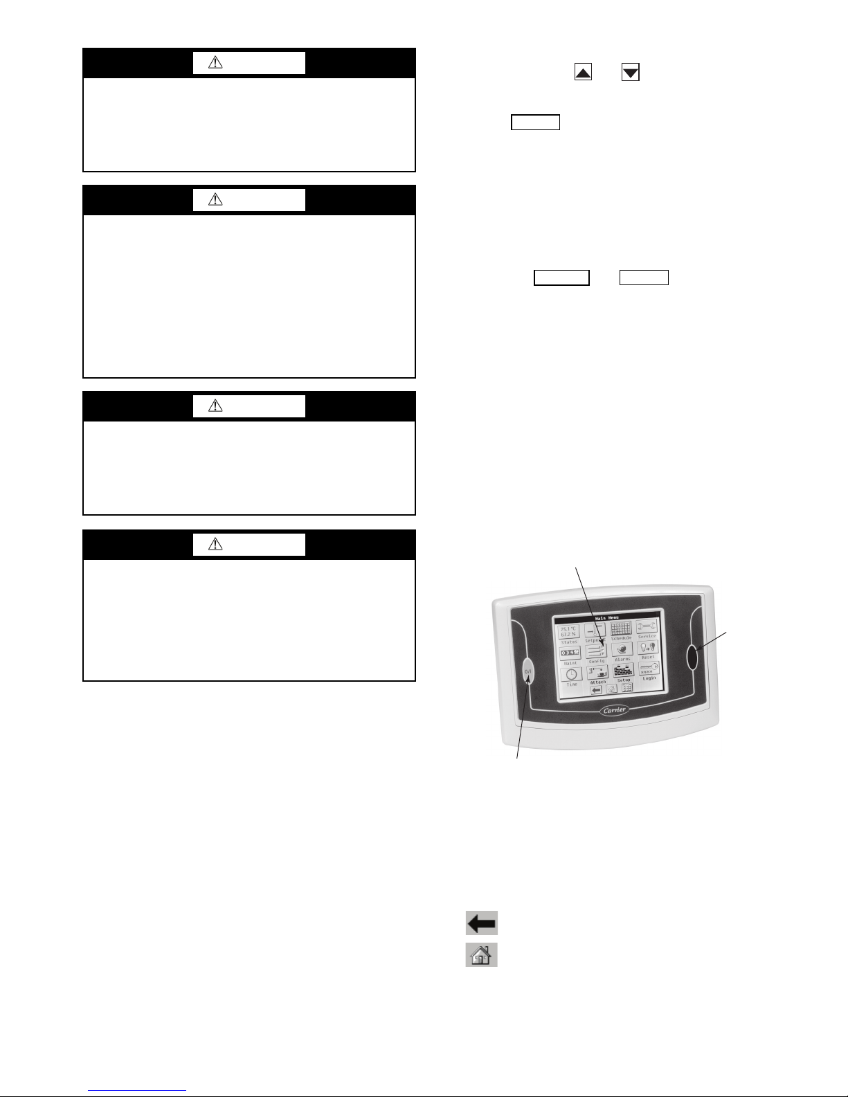
TOUCH PILOT DISPLAY — The Touch Pilot display is the
standard user interface for the AquaForce 30XA chillers with
the ComfortLink control system. The display includes a large
LCD (liquid crystal display) touch screen for display and user
configuration, a Start/Stop button, and an Alarm Indicator LED
(light-emitting diode). See Fig. 1.
LCD TOUCH SCREEN
ALARM
INDICATOR
LIGHT
GENERAL
This publication contains Controls, Operation, Start-Up,
Service and Troubleshooting information for the 30XA080500 air-cooled liquid chillers with electronic controls. The
30XA chillers are equipped with ComfortLink™ controls and
electronic expansion valves. The AquaForce
offer two different user interface devices, the Touch Pilot™
display and the Navigator ™ display.
Conventions Used in This Manual — The follow-
ing conventions for discussing configuration points for the
Navigator module and Touch Pilot display will be used in this
manual.
Point names for the Touch Pilot display will be shown in
bold. See Appendix A for a complete list of point names. Item
names for the Navigator module will be shown in bold italics.
See Appendix B for the complete path name preceeding the
item name. The point and item names in Appendices A and B
will be listed in alphabetical order and the path name for each
will be written with the mode name first, then any sub-modes,
each separated by an arrow symbol (.
This path name will show the user how to navigate through the
Navigator module or the Touch Pilot display to reach the desired
®
30XA chillers
STA RT- STOP
BUTTON
The Touch Pilot display can be used to access various
Carrier Comfort Network
®
devices. For operation under these
circumstances, contact your Carrier representative.
Operation of the Touch Pilot display is driven from the
displays on the touch screen. The Touch Pilot display uses the
following screen “buttons” to allow the user to operate the display and navigate within and between screens.
“BACK” Returns to the next higher screen in the
hierarchy.
“HOME” Displays the Default Group Display screen
for Touch Pilot display. The Default Screen is a userconfigured display of up to 9 points on each of 8 screens. This
allows for quick access to various, frequently viewed points,
without navigating through the Main Menu structure. This button is available at all menu levels and returns the user to the
first Default Group Display screen.
3
612
Page 4
“MAIN MENU” Displays the Main Menu screen.
Fig. 2 — Group Display Screen
Fig. 3 — Point Data Dialog Box
a30-4470
a30-4471
This allows access for viewing and configuration,
where possible, of all points supported by the controller. This
includes points such as set point and operational configuration.
This button is available at all menu levels and returns the user
to the Main Menu screen.
“PREVIOUS” In a group of sequential screens of the
same type, pressing this button moves the user to the
next earlier screen in the group.
“NEXT” In a group of sequential screens of the same
type, pressing this button advances the user to the next
screen in the group.
“OK” Agrees with, or says “yes” to a prompt and per-
forms the appropriate processing.
“NO” Rejects, or says “no” to a prompt and performs
the appropriate processing.
“CANCEL” Terminates an ongoing action and returns
to the current screen without any other processing.
“CLEAR DATA” Clears the data value in a data entry
dialog box. This button is used to clear incorrect data.
“RESET DATA” Zeros the data value in a data entry
dialog box.
“ADD” Adds the active point to a Group Display
screen.
“REMOVE” Deletes a point from a Group Display
screen.
“INCREASE” Modifies the value of a field within its
defined limits or “SCROLL UP” and shifts the screen
view up by one item.
“DECREASE” Modifies the value of a field within its
defined limits or “SCROLL DOWN” and shifts the
screen view down by one item.
“PAGE DOWN” If the current table or list has more
data than will fit on the screen, pressing this button
will replace the items currently on the screen with the next
group of items.
“PAGE UP” If the current table or list has more data
than will fit on the screen, pressing this button will
replace the items currently on the screen with the previous
group of items.
“FORCE” Begins the process of forcing or overriding
the value of a point.
“AUTO” Begins the process of removing a force from
a point.
“MODIFY” Begins the process of modifying a con-
figuration value.
“ALARM INDICATOR LIGHT” An LED alarm
indicator light is activated when a new alarm condi-
tion occurs. The alarm indicator light, located on the
right side of the display, remains activated until it is manually
reset using the Reset button on the Main menu.
“START/STOP BUTTON” The Touch Pilot™ dis-
play includes an equipment Start/Stop Button that
enables the user to start or stop the chiller from the
display. See Enable-Off-Remote Contact Switch (SW1) on
page 17 for additional information.
Several items are password protected. When required, a
Password dialog box will be displayed for field input of the
password. The default password is 3333. The password can be
changed if desired.
Power-Up Display
— When the Touch Pilot display is powered up, it displays an initialization progress bar and attaches
(initiates communication) to the Main Base Board. The Touch
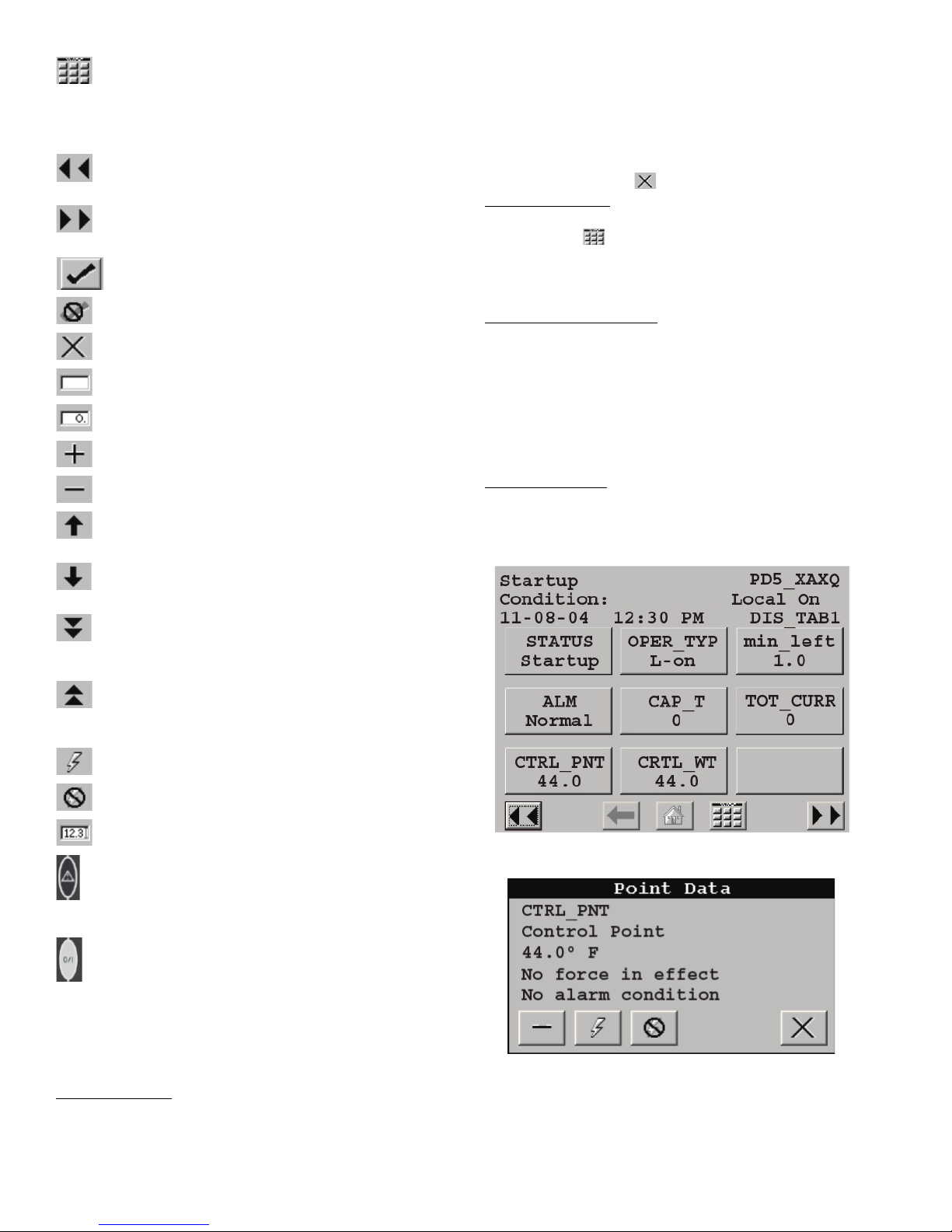
Pilot display then shows that controller’s default Group Display screen. See Fig. 2. This is a user-configured display screen
with up to 9 points on 8 separate screens. For more information
on adding or removing points from the Group Display screen,
see the Group Display Screens section on page 6.
Touch any of the screen point buttons and Point Data Dialog
box will be displayed with expanded information. In the example shown below, the CTRL_PNT button in the bottom left
corner was selected. See Fig. 2 and 3.
To exit the box, press .
Main Menu Display
— The default screen for the Touch Pilot
controller is the Group Display screen. To access the Main
Menu, press the button. The screen shown in Fig. 4 will be
displayed. Selecting a button will display the screens associated with that category. The user can also access the login screen
from the Main Menu if needed.
Touch Pilot Menu Structure
— The user can navigate through
the Touch Pilot display screens by selecting the buttons that appear on the screen. When a button is selected, either a submenu or a list of point names and values will be shown. Submenus will display a list of associated point names. See Fig. 5
for the Touch Pilot menu structure.
If the list of point names and values are shown, the top line
of the display is the table name. The line and total line counter
is displayed in the upper right corner of the display. Selecting
an item will cause a Point Data dialog box to appear.
Setup Menu Screen
— The Setup Menu screen, shown in
Fig. 6, is accessed by pressing the Setup button from the Main
Menu. This configuration allows the user to configure the basic
operation and look of the display. Table 1 summarizes the Setup Menu functions.
4
Page 5
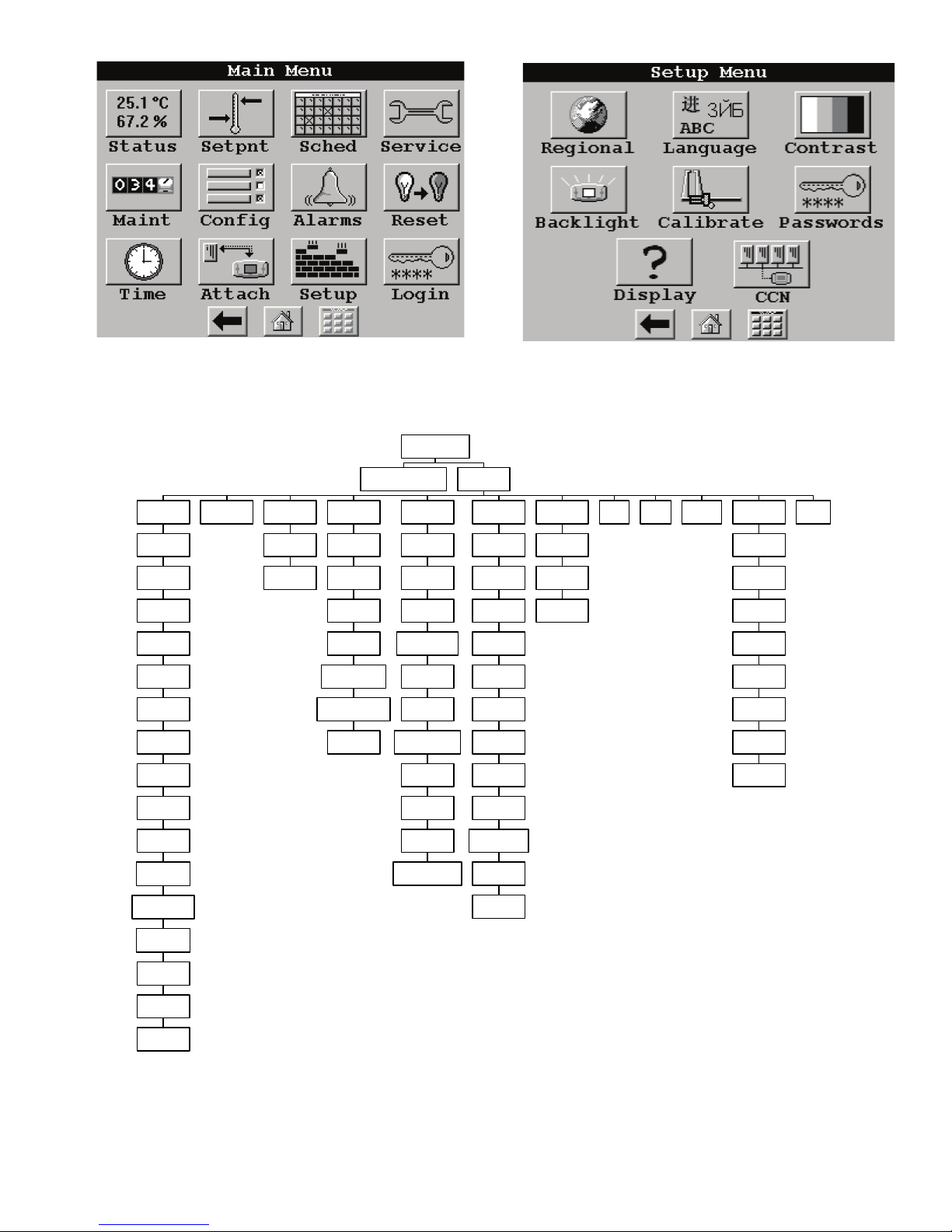
Fig. 4 — Main Menu Display
a30-4472
Fig. 6 — Setup Menu Display
a30-4474
User interface
Group display x 8 Main menu
Status
GENUNIT
CIRCA_AN
CIRCA_D
CIRCB_AN
CIRCB_D
CIRCC_D
CIRCC_AN
STATEGEN
RECLAIM
MODES
STRTHOUR
FANHOURS
FREECOOL
QCK_TST1
QCK_TST2
SERV_TST
Setpoint Schedule
OCC1PO1S
OCC2PO2S
Service
FACTORY
FACTORY2
SERVICE1
CP_UNABL
UPDTHOUR
UPDHRFAN
MAINTCFG
Maint
LOADFACT
FANCTRL
M_MSTSLV
DEFROSTM
LAST_POR
PR_LIMIT
BOARD_PN
SERMAINT
EXV_CTRL
CUR_PHAS
OCCDEFCFM
Config
Ctrl-ID
DISPCONF
USER
MST_SLV
CFG_TAB1
…
…
CFG_TAB8
BRODEFS
OCCDEFCS
HOLIDAY
ALARMDEF
Alarms
ALARHIST
ALARHIS2
ALAM_CUR
Reset Time Attach Setup
Regional
Language
Contrast
Backlight
Calibrate
Password
Display
CCN
Login
Fig. 5 — Touch Pilot™ Display Menu Structure
a30-4473
5
Page 6
Table 1 — Setup Menu
SETUP MENU BUTTON FUNCTION
This button specifies the time and date format and the base unit of measure. Time display can be configured as 12-
REGIONAL
LANGUAGE
CONTRAST
BACKLIGHT This button specifies whether backlighting should be kept on at all times or turned off during inactive periods.
CALIBRATE
PASSWORDS
DISPLAY
CCN This button is used to configure the bus and element numbers and the baud rate of the control on the network.
hour AM/PM setting or as a 24-hour setting. The date can be formatted in one of 3 settings, MM-DD-YYYY (MonthDay-Year), DD-MM-YYYY (Day-Month-Year), or YYYY-MM-DD (Year-Month-Day). Units of measure can be either US
(English) or Metric (SI).
This button selects the active language and font of the display. Available languages are English and Spanish (Espanol).
If a preferred language is not available, additional software for the Main Base Board (MBB) and the Touch Pilot™ display are required. Contact your Carrier representative for instructions and software.
This button adjusts the LCD contrast. Press and hold the [MOON] button to increase/darken the contrast or the [STAR]
button to decrease/lighten the current contrast.
NOTE: Touching the screen anywhere for 5 seconds while powering-up will prompt the user to restore contrast and
calibration settings to factory defaults.
This button is used to adjust the LCD touch screen calibration. Touch the screen in the circular targets located first in
the upper left and then in the lower right corner of the screen to adjust.
This button is used to configure the limited and full logged-in access system passwords. In order to change passwords,
the user must be logged in with full access to view and change the passwords. All passwords must consist of 4-digits,
which can be entered using the numeric keypad. Access levels and associated privileges are as follows:
Limited Logged-in Access - Provides the user with read/write access to all available tables (except service configuration tables, where the user will not be permitted to modify point data, and Group Display tables, where the user will not
be permitted to add points.) This access level also provides read/write access to all Touch Pilot display setup properties
except Display, CCN, and Password.
Full Logged-in Access - Provides user with read/write access to all available tables for the attached device and all
Touch Pilot display properties.
If the user does not log in, read-only access to all tables is allowed. The user will be prompted to log in when attempting
to access password-required functions.
This button is used to view the description data and part number from the Ctlr-ID Table and to specify the Operating
Mode. The Operating mode can be configured for Equipment mode or Network mode. For Touch Pilot displays that are
standard with the unit, Operating mode should not be changed from Equipment mode. Equipment mode provides
access only to the chiller’s MBB via the Local Equipment Network (LEN) Bus. For remote access, a remote Touch Pilot
display can be set to Network mode. Network mode provides access to all devices on the CCN (Carrier Comfort Net-
®
work
) bus.
NOTE: When changing the operating mode, a power cycle is required in order for the new operating mode to take
effect. The user should view and correct the following CCN data: address and baud rate, alarm acknowledger, and
broadcast acknowledger designation.
Setting the Time and Date
— The ComfortLink™ control has
a time and date function. This can be useful for diagnostics to
determine when alarms occur. The control is factory configured for the proper date and is set for the Eastern Time Zone.
The date and time zone must be checked and corrected if necessary, to allow the machine to function on an internal time
schedule and to display a proper time and date stamp for
alarms. The time and date is displayed on the Group Display
Screen.
To change the Time and Date, press the Main Menu
button. Select Time. On the display, a day and date box
with a time box will be shown. To change the day and date,
press the day and date box. A calendar will be displayed. If the
correct month is displayed, touch the correct date. If the wrong
month is displayed, use the or to change to the correct
month and select the correct date. The date will highlighted.
Press to accept the change. The previous screen will be
displayed with the corrected day and date shown. To correct
the time, use the or on the left to change the hour. Use
the or on the left to change the minutes. Continuously
touching the or will sequence the numbers. The time is
shown in a 24-hour format. To accept the changes, press the
or buttons. A “Save” dialog box is displayed with the
words, “Do you wish to save changes?” Press to accept
the changes.
Group Display Screens
— The Touch Pilot™ display supports up to eight Group Display screens. Group Display
screens show status information along the top of the screens
and nine buttons that display nine point names and point values
that are chosen by the user. All Group Display screen points are
user configurable. The bottom line of the screen contains navigation buttons that can be used to move between the Group
Display screens.
Pressing a point button will show that point’s Point Data
dialog box. See Fig. 2 and 3. This box contains buttons that
remove the point from the group display and apply or remove a
force (point override). When touching any button in the display
screen, the button will be outlined to acknowledge input. There
may be a delay in response to input, but if the button is outlined, do NOT press any other button until the previous input
has been processed.
If there is a communication failure with the MBB (Main
Base Board), all point buttons will be displayed in inverse video and the message Communication Failure will be displayed
in the top left line of the screen.
Default Group Designation — The default group is the first of
the 8 Group Display screens. This is the default screen of the
display. Information on this screen as well as the other 7
screens can be user-modified to meet the needs of the site.
To Add a Point To a Group Display — From the Main Menu,
press the desired menu button (Status, Setpoint, Service,
Maint, or Config) and, if necessary, the sub-menu button to
access the point to be added. Press the point button to show the
source point’s Point Data dialog box. See Fig. 3. From the
Point Data dialog box, press the ADD button. The display will
show the last Group Display accessed. Use the navigation buttons to access the destination Group Display. Press an existing
6
Page 7
point button or a blank button to update the highlighted button
ENTER
ESCAPE
ESCAPE
ENTER
ESCAPE
ENTER
ESCAPE
ESCAPE
ENTER
ENTER
ENTER
ENTER
ESCAPE
ENTER
ENTER
Run Status
Service Test
Temperatures
Pressures
Setpoints
Inputs
Outputs
Configuration
Time Clock
Operating Modes
Alarms
ENTER
ESC
MODE
Alarm Status
ComfortLink
Fig. 7 — Navigator Display Module
a30-3924
with the source point’s name. Press to add the highlighted
point to the group and return to the table display.
To Remove a Point From a Group Display — From the Point
Data Dialog box, press the REMOVE button and follow the
prompts. The display will return to the Group Display screen
from which the point was removed, and the button corresponding to the deleted point will be blank and disabled.
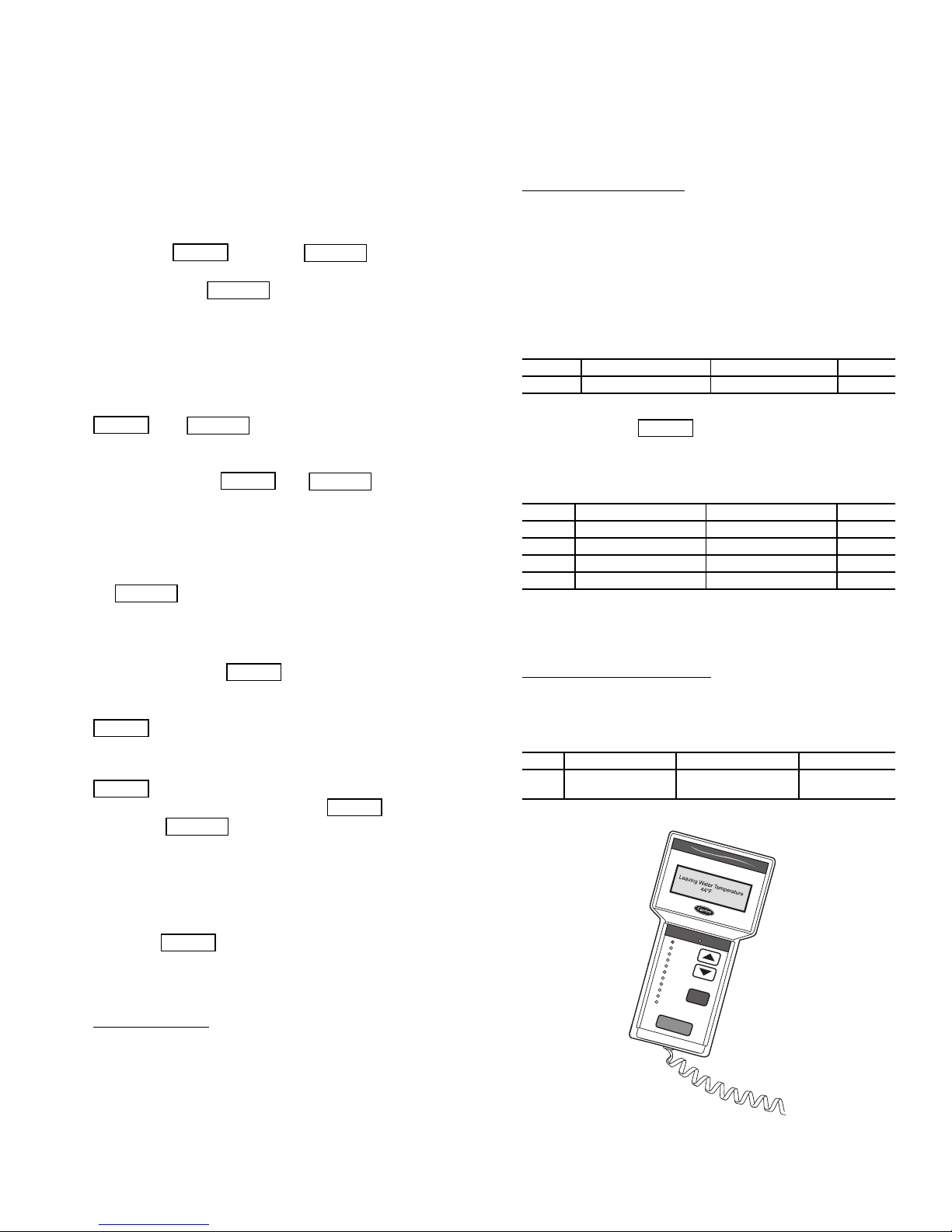
NAVIGATOR™ DISPLAY MODULE — The Navigator display module provides a mobile user interface to the
ComfortLink control system. The display has up and down arrow keys, an key, and an key. These keys
are used to navigate through the different levels of the display
structure. Press the key until ‘Select a Menu Item’ is
displayed. Use the up and down arrow keys to move through
the top 11 mode levels indicated by LEDs on the left side of the
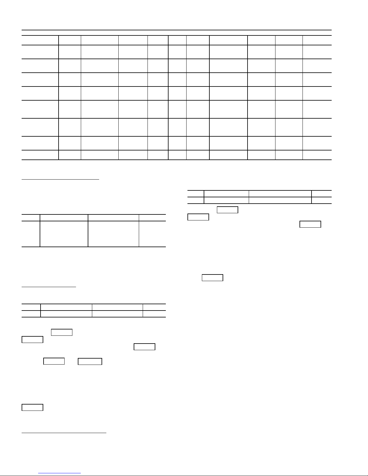
display. See Fig. 7. See Table 2 and Appendix B for more details about the display menu structure.
Once within a mode or sub-mode, a “>” indicates the
currently selected item on the display screen. Pressing the
and keys simultaneously will put the
Navigator module into expanded text mode where the full
meaning of all sub-modes, items, and their values can be displayed. Pressing the and keys when the
display says ‘Select Menu Item’ (Mode LED level) will return
the Navigator module to its default menu of rotating display
items (those items in Run StatusVIEW). In addition, the
password will be disabled, requiring that it be entered again before changes can be made to password protected items. Press
the key to exit out of the expanded text mode.
When a specific item is located, the item name appears on
the left of the display, the value will appear near the middle of
the display and the units (if any) will appear on the far right of
the display. Press the key at a changeable item and
the value will begin to flash. Use the up and down arrow keys
to change the value, and confirm the value by pressing the
key.
Changing item values or testing outputs is accomplished in
the same manner. Locate and display the desired item. Press
so that the item value flashes. Use the arrow keys to
change the value or state and press the key to accept
it. Press the key to return to the next higher level of
structure. Repeat the process as required for other items.
Items in the Configuration and Service Test modes are password protected. The words Enter Password will be displayed
when required, with 1111 also being displayed. The default
password is 0111. Use the arrow keys to change each number
and press to accept the digit. Continue with the
remaining digits of the password. The password can only be
changed through CCN operator interface software such as
®
, ComfortVIEW™ and Service Tool.
— When the Navigator display is powered
ComfortLink
Navigator
By
Carrier
ComfortWORKS
Power-Up Display
up it will display:
This indicates an initialization period while the Navigator™
display initiates communication with the Main Base Board.
Once communication is established, the default rotating
display will be shown. If communication is not established, the
Navigator module will display:
Communication
Failure
If the Navigator module is connected to a Main Base Board
without software loaded, the display will remain at the
powered-up initialization display.
Setting the Time and Date
— The ComfortLink control has a
time and date function. This can be useful for diagnostics to determine when alarms occur. The control is factory configured
for the proper date and for use in the Eastern Time Zone. The
control must be checked and corrected if necessary. The correct
time is important if the machine is to function on an internal
time schedule and display a proper time and date stamp for
alarms. The time and date will be displayed on the default rotating display of the Navigator module. The time and date can
also be checked and changed under the Time Clock mode as
described below.
ITEM ITEM EXPANSION PATH VALUE
HH.MM Time of Day Time ClockTIME XX.XX
To change the time, press the arrow key to move to the correct hour and press . The minutes can be changed in a
similar manner.
To check or change the date, the following items must be
checked and changed if necessary.
ITEM ITEM EXPANSION PATH VALUE
MNTH Month of Year Time ClockDATE WW
DOM Day of Month Time ClockDATE XX
DAY Day of Week Time ClockDATE YY
YEAR Year of Century Time ClockDATE ZZ
NOTE: WW is the current month of the controller, (01=January,
02=February, etc.).
XX is the current day of the month
YY is the day of the week, (01=Monday, 02-Tuesday, etc.)
ZZ is the year of the century, (06=2006, 07=2007)
Changing the Unit of Measure — The Navigator display has
two options for unit of measure on the display, English or SI
(metric). The factory default for the units of measure is
English. To change the unit of measure, the following item
must be changed.
ITEM ITEM EXPANSION PATH VALUE
METR Metric Display ConfigurationDISP
OFF – English
ON – SI (Metric)
7
Page 8
RUN
ENTER
ENTER
ENTER
ENTER
ESCAPE
ENTER
ENTER
ENTER
ENTER
ENTER
STATUS
Auto Display
(VIEW)
Machine
Starts/Hours
(RUN)
Compressor
Run Hours
(HOUR)
Compressor
Starts
(STRT)
Fan Run
Hours
(FAN)
Compressor
Disable
(CP.UN)
Predictive
Maintenance
(MAIN)
Software Versions
(VERS)
SERVICE
TEST
Manual
Test Mode
(TEST)
Quick
Test Mode
(QUIC)
Table 2 — ComfortLink™ Navigator™ Display Menu Structure
MODE
TEMPERATURES PRESSURES
Unit
Temperatures
(UNIT)
Circuit A
Temperatures
(CIR.A)
Circuit B
Temperatures
(CIR.B)
Circuit C
Temperatures
C)
(CIR.
Circuit A
Pressures
(PRC.A)
Circuit B
Pressures
(PRC.B)
Circuit C
Pressures
(PRC.C)
SET
POINTS
Cooling
Setpoints
(COOL)
Heating
Setpoints
(HEAT)
Misc.
Setpoints
(MISC)
INPUTS OUTPUTS CONFIGURATION
General
Inputs
(GEN.I)
Circuit A
Outputs
(CIR.A)
Circuit B
Outputs
(CIR.B)
Circuit C
Outputs
(CIR.C)
General
Outputs
(GEN.O)
Display
Configuration
(DISP)
Unit
Configuration
(UNIT)
Service
Configurations
(SERV)
Options
Configuration
(OPTN)
Reset,
Demand Limit,
Master/Slave
(RSET)
TIME
CLOCK
Time of Day
(TIME)
Day, Date
(DATE)
Schedule 1
(SCH1)
Schedule 2
(SCH2)
Holidays
(HOLI)
Service
Maintenance
Configuration
(MCFG)
OPERATING
MODES
Operating
Control Type
(SLCT)
Operating
Modes
(MODE)
ALARMS
Reset Current
Alarms
(R.ALM)
Current
Alarms
(ALRM)
Alarm
History
(H.ALM)
Changing the Display Language
— The Navigator display
has five language options to select from, English, Espanol,
Francais, Portugues, and Translated. The “Translated” option is
not supported at this time. The factory default language is
English. To change the display language, the following item
must be changed.
ITEM ITEM EXPANSION PATH VALUE
English
LANG Language Selection ConfigurationDISP
Espanol
Francais
Portugues
Translated
NOTE: When the Language Selection (Configuration
DISPLANG) variable is changed, all appropriate display
expansions will immediately change to the new language. The
four letter/digit code will not change. No power-off or control
reset is required when reconfiguring languages.
Adjusting the Contrast
— The contrast of the display can be
adjusted to suit ambient conditions. To adjust the contrast, enter
the LED Test mode of the device.
ITEM ITEM EXPANSION PATH VALUE
TEST Test Display LEDs ConfigurationDISP
Pressing will access the TEST point. Pressing
again will cause the “OFF” to flash. Use the up or
down arrow to change “OFF” to “ON.” Pressing will
illuminate all LEDs and display all pixels in the view screen.
Pressing and simultaneously allows the
user to adjust the display contrast. The display will read:
Adjust Contrast
- - - -+ - - - - - - - - - - - - - - Use the up or down arrows to adjust the contrast. The
screen’s contrast will change with the adjustment. Press
to accept the change. The Navigator module will
keep this setting as long as it is plugged in to the LEN (Local
Equipment Network) bus.
Adjusting the Backlight Brightness
— The backlight of the
display can be adjusted to suit ambient conditions. The factory
default is set to the highest level. To adjust the backlight of the
Navigator module, enter the LED Test mode of the device.
ITEM ITEM EXPANSION PATH VALUE
TEST Test Display LEDs Configuration ModeDISP
Pressing will access the TEST point. Pressing
again will cause the “OFF” to flash. Use the up or
down arrow to change “OFF” to “ON.” Pressing will
illuminate all LEDs and display all pixels in the view screen.
Pressing the up and down arrow keys simultaneously allows
the user to adjust the display brightness. The display will read:
Adjust Brightness
- - - - - - - - - - - - - - - - - +
Use the up or down arrow keys to adjust screen brightness.
Press to accept the change. The Navigator module
will keep this setting as long as it is plugged in to the LEN bus.
CONTROLS
General —
ComfortLink™ electronic control system that controls and
monitors all operations of the chiller. The control system is
composed of several components as listed in the following sections. All machines have a Main Base Board (MBB), Touch Pilot™ module, electronic expansion valve board (EXV), fan
board, Compressor Protection board, Emergency On/Off
switch, and an Enable-Off-Remote Contact switch.
The 30XA air-cooled liquid chillers contain the
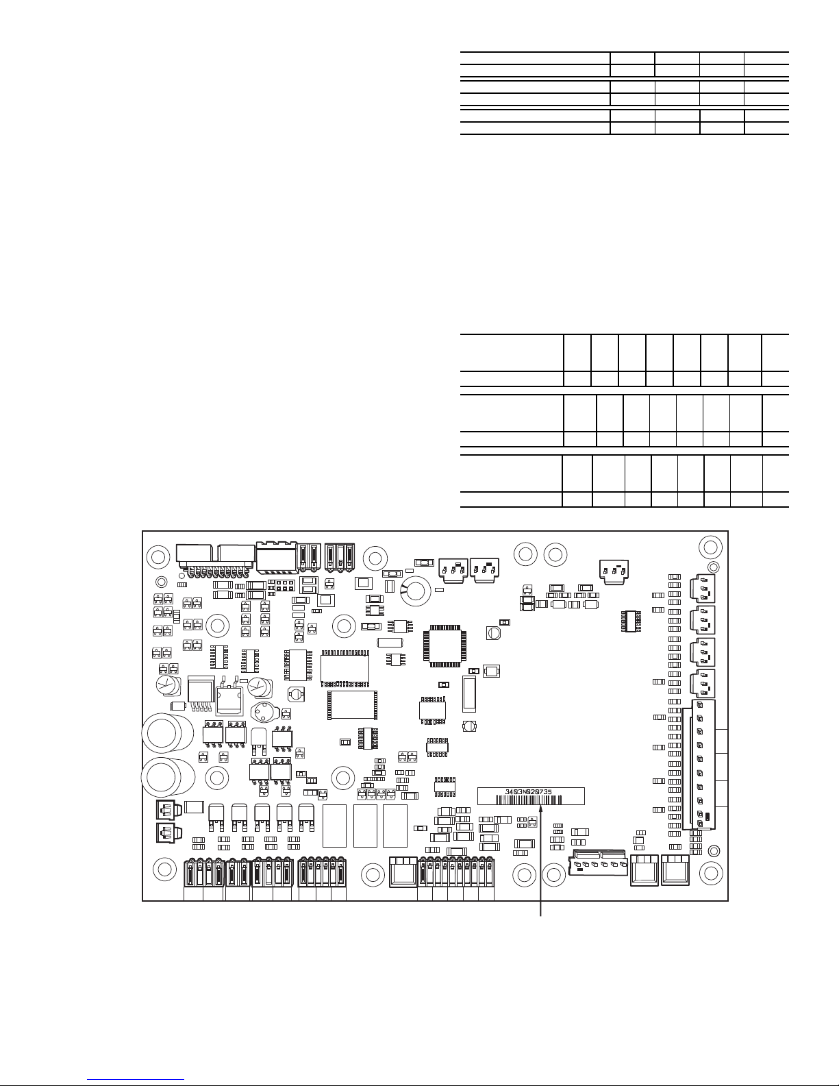
Main Base Board (MBB) — The MBB is the core of
the ComfortLink control system. It contains the major portion
of operating software and controls the operation of the
machine. See Fig. 8. The MBB continuously monitors input/
output channel information received from its inputs and from
all other modules. The MBB receives inputs from status and
feedback switches, pressure transducers and thermistors. The
MBB also controls several outputs. Some inputs and outputs
that control the chiller are located on other boards, but are
transmitted to or from the MBB via the internal communications bus. Information is transmitted between modules via a 3wire communication bus or LEN (Local Equipment Network).
The CCN (Carrier Comfort Network
Connections to both LEN and CCN buses are made at TB3.
®
) bus is also supported.
8
Page 9
For a complete description of Main Base Board inputs and out-
Fig. 8 — Main Base Board
a30-4255
puts and their channel identifications, see Table 3.
Compressor Protection Module (CPM) — There
is one CPM per compressor. See Fig. 9. The device controls the
compressor contactors, oil solenoid, loading/unloading the
solenoid, motor cooling solenoid (30XA080,082 only) and the
oil separator heater. The CPM also monitors the compressor
motor temperature, high pressure switch, oil level switch, discharge gas temperature, oil pressure transducer, motor current,
MTA (must trip amps) setting and economizer pressure transducer. The CPM responds to commands from the MBB (Main
Base Board) and sends the MBB the results of the channels it
monitors via the LEN (Local Equipment Network). The CPM
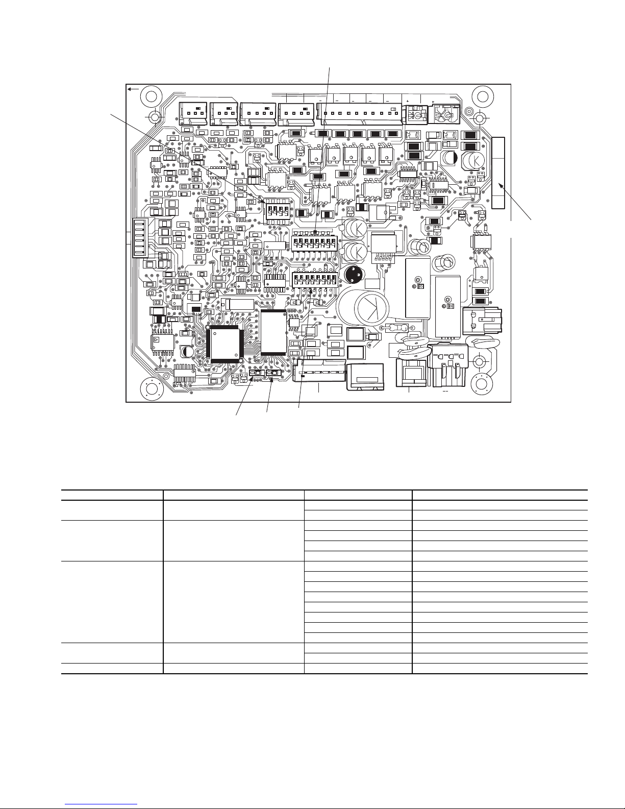
has three DIP switch input banks, Switch 1 (S1), Switch 2 (S2),
and Switch 3 (S3). The CPM board DIP switch (S1) configures
the board for the type of starter, the location and type of the
current transformers and contactor failure instructions. See Table 4 for description of DIP switch 1 (S1) inputs. See Appendix
D for DIP switch settings.
The CPM board DIP switch S2 setting determines the must
trip amps (MTA) setting. See Appendix D for DIP switch settings. The MTA setting which is calculated using the settings
S2 must match the MTA setting in the software or an MTA
alarm will be generated.
See below for CPM board DIP switch S3 address information. See Table 5 for CPM inputs and outputs.
CPM-A DIP Switch 1 2 3 4
Address: OFF OFF OFF OFF
CPM-B DIP Switch 1 2 3 4
Address: OFF OFF ON OFF
CPM-C DIP Switch 1 2 3 4
Address: OFF OFF OFF ON
NOTE: The CPM-A and CPM-B DIP switches are for all
units. The CPM-C DIP switches are for 30XA400-500 units.
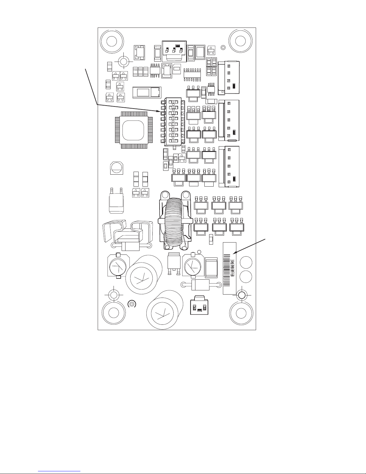
Electronic Expansion Valve (EXV) Board —
The 30XA080,082 unit has one EXV board. The 30XA090500 units have one EXV board per circuit. See Fig. 10. The
board is responsible for monitoring the suction gas temperature
and economizer gas temperature thermistors. The board also
signals the main EXV and economizer EXV (ECEXV) motors
to open or close. The electronic expansion valve board
responds to commands from the MBB and sends the MBB the
results of the channels it monitors via the LEN (Local Equipment Network). See below for DIP switch information. See
Tables 6 and 7 for EXV inputs and outputs.
EXV BOARD A
(080-500)
DIP SWITCH
Address: ON ON ON ON ON ON OFF ON
EXV BOARD B
(090-500)
DIP SWITCH
Address: OFF ON ON ON ON ON OFF ON
EXV BOARD C
(400-500)
DIP SWITCH
Address: ON OFFONONONONOFFON
123456 7 8
1 23456 7 8
1 2 3456 7 8
J1A
J10
12/11
12/11
221
221
221
TR1 TR2 TR3 TR4 TR5
MOV1
24 VAC
C41
C42 C43
C32
C33
J2A
CH19 CH20 CH21 CH22 CH23 CH24 CH25 CH26
C34
J2B
CCN J13 J9D
221
RELAY
C35
OUTPUTS
J2C
+ G -
K1
D15
J3
CCN
K2
ANALOG
INPUTS
STATUS
J8
CH10
SIO
(LEN)
11
CH11 CH12
+ G –
195
195
LEN
J9C
CH13
LEN
+ G –
J9B
195
195
195
CH14
195
C16
J4
CH
15A
LOCATION OF
SERIAL NUMBER
195
15a
CH
DISCRETE
+C+CCH
LEN
+ G –
J9A
INPUTS
J5A
16a+CCH16b
J7A J7B J7C J7D
THERMISERS PRESSURES
J5B
CH17
J6
J5C
CH18
CH6 CH7 CH8 CH9
CH5
CH4
CH1 CH2 CH3
9
Page 10
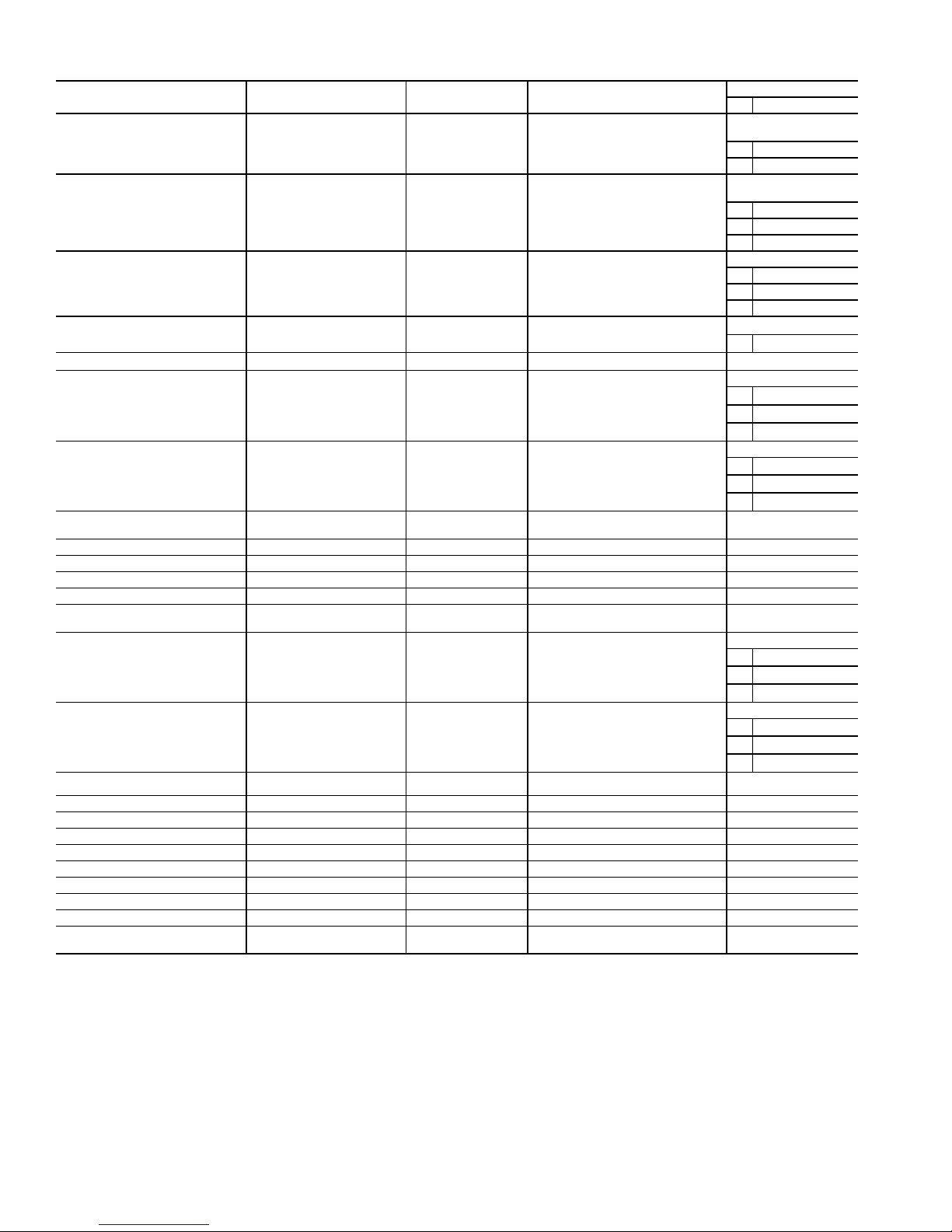
Table 3 — Main Base Board Inputs and Outputs
DESCRIPTION INPUT/OUTPUT I/O TYPE DISPLAY MODULE POINT NAME
Power (24 vac supply) —— —
Local Equipment Network —— —
Carrier Communication
Network
Chilled Water Flow Switch CWFS Switch Cooler Flow Switch, LOCK
Demand Limit Switch No. 1 Demand Limit SW1 Switch Limit Switch 2 Status, DLS1 MBB-J4-CH13
Circuit A Discharge
Pressure Transducer
Circuit B Discharge
Pressure Transducer
Dual Chiller
LWT Thermistor
Dual Set Point Input Dual Set Point Switch Remote Setpoint Switch, DUAL MBB-J4-CH12
Entering Water Thermistor EWT 5k Thermistor Cooler Entering Fluid, EWT MBB-J6-CH2
Leaving Water Thermistor LWT 5k Thermistor Cooler Leaving Fluid, LWT MBB-J6-CH1
Outdoor Air Thermistor OAT 5k Thermistor External Temperature, OAT MBB-J6-CH4
External Chilled
Water Pump Interlock
Circuit A Suction
Pressure Transducer
Circuit B Suction
Pressure Transducer
Unit Status Remote Contact-Off-Enable Switch On/Off Remote Switch, ONOF MBB-J4-CH11
Alarm Relay ALM R Relay Alarm Relay Output, ALRM MBB-J3-CH24
Alert Relay ALT R Relay Alert Relay Output, ALRT MBB-J3-CH25
Cooler Heater CL-HT Contactor Cooler Heater Command, CO.HT MBB-J3-CH26
Isolation Valve A ISVA Contactor Ball Valve Position, BVL.A MBB-J2A-CH19
Isolation Valve B ISVB Contactor Ball Valve Position, BVL.B MBB-J2A-CH20
Isolation Valve C (Size 400-500) ISVC Contactor Ball Valve Position, BVL.C MBB-J2C-CH22
Oil Heater A (Size 080, 082 only) OIL HT_A Contactor Circuit A Oil Heater, HT.A MBB-J2C-CH22
Oil Heater B (Size 080, 082 only) OIL HT_A Contactor Circuit B Oil Heater, HT.B MBB-J2C-CH23
Pump #1 Interlock
Pump #2 Interlock
LEGEND
I/O — Input or Output
LWT — Leaving Water Temperature
—— —
DPTA Pressure Transducer Discharge Pressure, DP.A
DPTB Pressure Transducer Discharge Pressure, DP.B
DUAL 5k Thermistor CHWS Temperature, CHWS MBB-J6-CH3
PMPI Switch Electrical Box Interlock, ELEC MBB-J4-CH15A
SPTA Pressure Transducer Suction Pressure, SP.A
SPTB Pressure Transducer Suction Pressure, SP.B
PMP1
PMP2
Switch Cooler Pump Run Status, PUMP MBB-J5C-CH18
CONNECTION POINT
Pin Notation
MBB-J1, MBB-J1A,
MBB-J1B
11 24 vac
12 Ground
MBB-J9A, MBB-J9B,
MBB-J9C, MBBJ9D
+RS485 Port (D+)
G RS485 Port (Gnd)
- RS485 Port (D-)
MBB-J12
+RS485 Port (D+)
G RS485 Port (Gnd)
- RS485 Port (D-)
MBB-J5B-CH17
17
MBB-J7A-CH6
5V +5 vdc Ref.
SSignal
RReturn
MBB-J7C-CH8
5V +5 vdc Ref.
SSignal
RReturn
MBB-J7B-CH7
5V +5 vdc Ref.
SSignal
RReturn
MBB-J7D-CH9
5V +5 vdc Ref.
SSignal
RReturn
10
Page 11
123 45678
0N
40
K
123 45678
0N
40
K
123 4
0N
102
151
102
102
101
101
101
101
100 K
620
561
2x
151
151
151 151 151
151
151
151
151
561
561
2
2x
2
CH
05
CH
06
C
C
CH
10
CH
11
CH
12
CH
13CH14
J2
J11
11
12
J9
J10A
J10B
24 VDC/OLL
HPS
1
LOADERS OLS MOTOR COOLING
OIL
PRESS
CH01
CH02
CH03
CH04
SMT
MOT
TMP
DG
TMP
R
R
R
R
S
5
S
5
AUX
102
102
100 K
CH
08
CH
07
01
02
J3
J5
J12
J1
151
151
R20
102
– G +
3 2 1
– G +
3 2 1
100K
101
PRESS
ECO
SI0 STATU S
CT1
CT2
CT3
J8
151
151
151
151
151
561
151
151
151
151
151
151
J4
CH
09
(LEN)
MTA
DIP
SWITCH 3
(S3)
S1
S2
S3
DIP
SWITCH 2
(S2)
DIP
SWITCH 1
(S1)
LOCATION OF
SERIAL NUMBER
STAT US
SIO
(LEN)
Fig. 9 — Compressor Protection Module
a30-4215
DIP SWITCH POSITION FUNCTION SETTING MEANING
1
2, 3
4, 5, 6
7
8 Not Used — —
Starter Configuration OFF Across-the-line Start
Current Transformer (CT) Position OFF (2), OFF (3) CT is located in the Delta of the motor
Current Transformer (CT) Selection OFF (4), OFF (5), OFF (6) 100A/1V CT1
Table 4 — DIP Switch 1 (S1) Inputs
ON Wye-Delta Start
ON (2), OFF (3) CT is located in the main line
OFF (2), ON (3) Reserved for future use
ON (2), ON (3) Invalid; will cause MTA configuration alarm
ON (4), OFF (5), OFF (6) 100A/0.503V CT2
OFF (4), ON (5), OFF (6) 100A/0.16V CT3
ON (4), ON (5), OFF (6) Invalid; will cause MTA configuration alarm
OFF (4), OFF (5), ON (6) Invalid; will cause MTA configuration alarm
ON (4), OFF (5), ON (6) Invalid; will cause MTA configuration alarm
OFF (4), ON (5), ON (6) Invalid; will cause MTA configuration alarm
ON (4), ON (5), ON (6) Invalid; will cause MTA configuration alarm
Contactor Failure Action OFF All units should be off
ON Used when Shunt Trip is available in the unit
11
Page 12
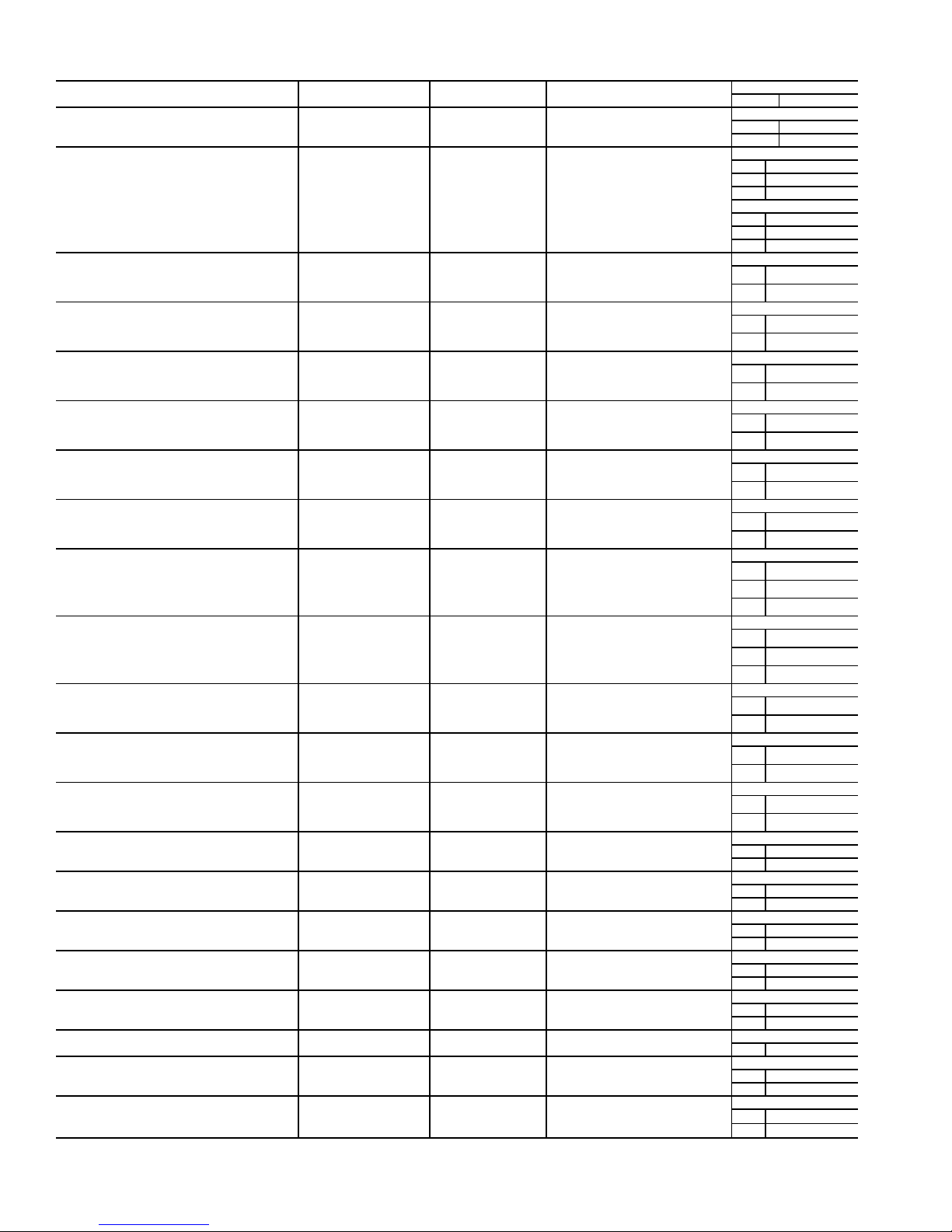
Table 5 — Compressor Protection Module Inputs and Outputs*
DESCRIPTION INPUT/OUTPUT I/O TYPE DISPLAY MODULE POINT NAME
Power (24 vac supply) —— —
Local Equipment Network —— —
Circuit X High Pressure Switch HPS-X Switch Not available
Oil Level Switch Oil LS X Switch Circuit X Oil Solenoid, OLS.X
Must Trip Amps† MTA (S2) 8-Pin DIP Switch Must Trip Amps, MTA.X
Configuration Switch† S1 8-Pin DIP Switch S1 Config Switch, C.SW.X
Compressor X Motor Temperature MTR-X NTC Thermistor Motor Temperature, CTP.X
Compressor X Discharge Gas Temperature DGT X NTC Thermistor Discharge Gas Temp, DGT.X
Oil Pressure Transducer OPT X Pressure Transducer Oil Pressure, OP.X
Economizer Pressure Transducer EPT X Pressure Transducer Economizer Pressure, ECP.X
Compressor Current X Phase A Current Sensor CUR.A
Compressor Current X Phase B Current Sensor CUR.B
Compressor Current X Phase C Current Sensor CUR.C
Compressor X 1M Contactor C X 1M Contactor Compressor Output, CP.X
Compressor X 2M Contactor C X 2M Contactor Not available
Compressor X S Contactor C X S Contactor Not available
Oil Heater Relay X (090-500 Only)
Oil Solenoid X Oil solenoid-X Solenoid Oil Solenoid Output, OLS.X
Load Solenoid X Loading Solenoid-X Solenoid Slide Valve 1 Output, SL1.X
Unload Solenoid X Unloading Solenoid-X Solenoid Slide Valve 2 Output, SL2.X
Gas Cooling Solenoid X (080,082 Only) Gas Cooling Solenoid-X Solenoid DGT Cooling Solenoid, DGT.X
*“X” denotes the circuit, A, B or C.
†See Appendix D for MTA settings.
Oil HTR X Contactor Oil Heater Output, HT.X
CONNECTION POINT
Pin Notation
CPM-X-J1
11 24 vac
12 Ground
CPM-X-JP12
1 RS485 Port (D+)
2 RS485 Port (Gnd)
3 RS485 Port (D-)
CPM-X-J12
1 RS485 Port (D+)
2 RS485 Port (Gnd)
3 RS485 Port (D-)
CPM-X-J7-CH05
1
2
CPM-X-J6-CH06
1
2
CPM-X-J9-CH01
1
2
CPM-X-J9-CH02
1
2
CPM-X-J10B-CH04
5V + 5 vdc ref
S Signal
RReturn
CPM-X-J10A
5V + 5 vdc ref
S Signal
RReturn
CPM-X-J8-CH01
1
2
CPM-X-J8-CH02
1
2
CPM-X-J8-CH3
1
2
CPM-X-J1-CH07
1
2
CPM-X-J2-CH8
1
2
CPM-X-J2-CH9
1
2
CPM-X-J2-CH10
1
2
CPM-X-J2-CH12
1
2
CPM-X-J2-CH13
1
CPM-X-J2-CH14
1
2
CPM-X-J2-CH10
1
2
12
Page 13
1
2
3
4
5
6
7
8
ON
100
100
257-01
712
100K
100K
100
1
2
3
4
5
3
2
1
-
G
+
J3
1
2
3
4
5
J2A EXVA
J2B EXVB
24VAC
STATUS
MOV1
LOCATION OF
SERIAL NUMBER
432 1
THA THB
D4
D6
J1
C15
C16
D5
U5
Q2 Q1
L4
U4
12/11
C17
+
Q45
Q42Q37
G2
Q35
Q25
Q27
Q30
Q20
Q22
Q17
Q15
Q12
Q10
C10
Q7
S1
C11
U2
D2
L1
U1
C37C39
SB
D15
U6
C25
C49
Q4Q5
L2
R2
R3 L3
D1
R9
TEMP
D29
D9 D8
SI0
(LEN)
COMM J4
DIP
SWITCH
Fig. 10 — EXV Board
a30-4216
13
Page 14
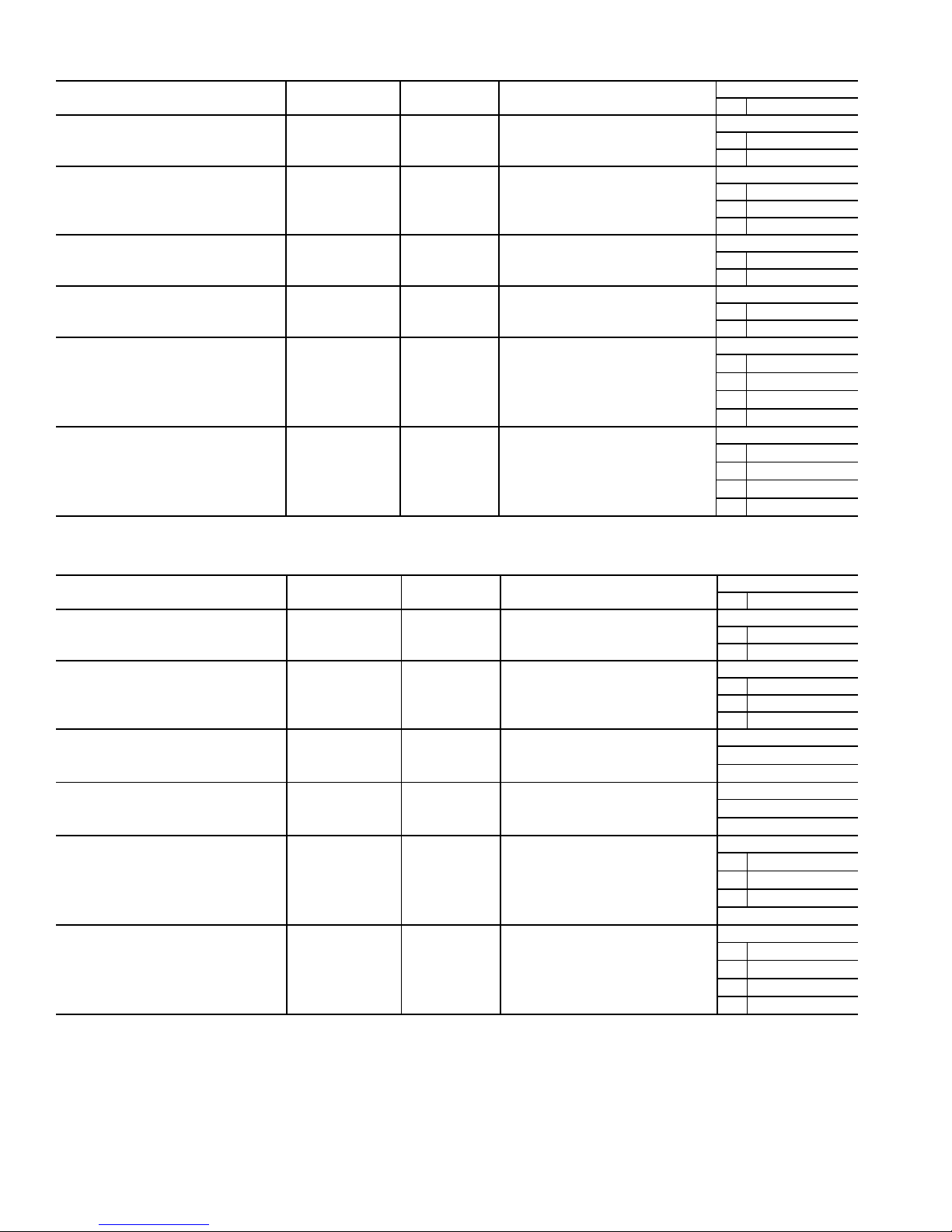
Table 6 — EXVA Board Inputs and Outputs (30XA080,082)
DESCRIPTION INPUT/OUTPUT I/O TYPE DISPLAY MODULE POINT NAME
Power (24 vac supply) —— —
Local Equipment Network —— —
Circuit A Suction Gas Thermistor SGTA 5k Thermistor Compressor Suction Temp, SGT.A
Circuit B Suction Gas Thermistor SGTB 5k Thermistor Compressor Suction Temp, SGT.B
Circuit A EXV EXV-A Stepper Motor EXV Position, EXV.A
Circuit B EXV EXV-B Stepper Motor EXV Position, EXV.B
CONNECTION POINT
Pin Notation
EXVA-J1
11 24 vac
12 Ground
EXVA-J4
1 RS485 Port (D+)
2 RS485 Por t (Gnd)
3 RS485 Port (D–)
EXVA-J3
TH
A
EXVA-J3
TH
B
EXVA-J2A
1
2
3
4
EXVA-J2B
1
2
3
4
Table 7 — EXV A,B,C Board Inputs and Outputs* (30XA090-500)
DESCRIPTION INPUT/OUTPUT I/O TYPE DISPLAY MODULE POINT NAME
Power (24 vac supply) —— —
Local Equipment Network ——
Circuit X Suction Gas Thermistor SGT X 5k Thermistor Compressor Suction Temp, SGT.X
Circuit X Economizer Gas Thermistor ECT X 5k Thermistor Economizer Gas Temp, ECT.X
Circuit X EXV EXV-X Stepper Motor EXV Position, EXV.X
Circuit X Economizer EXV ECEXV-X Stepper Motor Cir X Economizer EXV Pos, ECO.X
*“X” denotes the circuit, A, B or C.
—
CONNECTION POINT
Pin Notation
EXVX-J1
11 24 vac
12 Ground
EXVX-J4
1 RS485 Port (D+)
2 RS485 Port (Gnd)
3 RS485 Port (D–)
EXVX-J3
TH
A
EXVX-J3
TH
B
EXVX-J2A
1
2
3
4
EXVX-J2A
1
2
3
4
14
Page 15
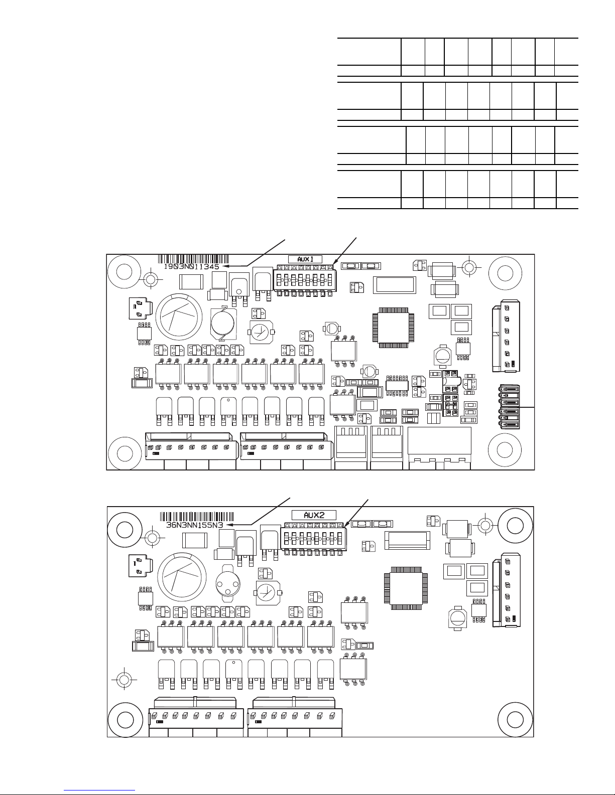
Fan Boards — At least one fan board is installed in each
1
2
3
4
5
6
7
8
ON
100K
100K
100K
CH1
CH2 CH3
CH4 CH5 CH6 CH7 CH8
TR1 TR2 TR3 TR4 TR5 TR6 TR7 TR8
STATU S SIO (LEN)
LOCATION OF
SERIAL NUMBER
24 VAC
CH13 CH14
J9
J1
CH9
CH10
CH11
CH12
JP2
C61
CH13
D12
JP1
L3
L5
U21
L2
D6
D5
Q5
Y1
D7
D8
S1
D3
U1
Q1
U5
U6
U7
U8
U9
Q10
Q11
U10
J4
J3
J2
U4
U2
Q12
Q60
3 2 1
– G +
3 2 1
– G +
DIP SWITCH
1
2
3
4
5
6
7
8
ON
100K
100K
100K
LOCATION OF
SERIAL NUMBER
TR1 TR2 TR3 TR4 TR5 TR6 TR7 TR8
CH1 CH2 CH3 CH4 CH5 CH6 CH7 CH8
STAT US SIO (LEN)
24 VAC
J1
J9
D4
U2
U5
Q2
Q7
Q3
U8
U9
Q9
Q10
Q11Q12
Q13
J4
J3
J2
S1
D7
Q5
Y1
D5
D6
L2
U6
U1
Q1
D3
C3
3 2 1
– G +
3 2 1
– G +
DIP SWITCH
Fig. 11 — Fan Board (AUX 1) with Low Ambient Temperature Head Pressure Control
Fig. 12 — Fan Board (AUX 2) without Low Ambient Temperature Head Pressure Control
a30-4046
a30-4047
unit. See Fig. 11 and 12. There are two types of fan boards.
One with and one without an analog output signal for the low
ambient temperature head pressure control fan speed controllers. If a unit does not have low ambient temperature head pressure control installed, it will not have the analog connection terminals. The fan board responds to commands from the MBB
and sends the MBB the results of the channels it monitors via
the Local Equipment Network (LEN). See below for fan board
A, B and C DIP switch addresses. See Tables 8-10 for inputs
and outputs.
FAN BOARD
(080,082)
123 45678
DIP SWITCH
Address: OFF ON OFF OFF ON OFF ON OFF
FAN BOARD A
(090-500)
DIP SWITCH
12345678
Address: OFF ON OFF OFF ON OFF ON OFF
FAN BOARD B
(140-500)
DIP SWITCH
123 45678
Address: ON ON OFF OFF ON OFF ON OFF
FAN BOARD C
(400-500)
12345678
DIP SWITCH
Address: OFF OFF ON OFF ON OFF ON OFF
15
Page 16
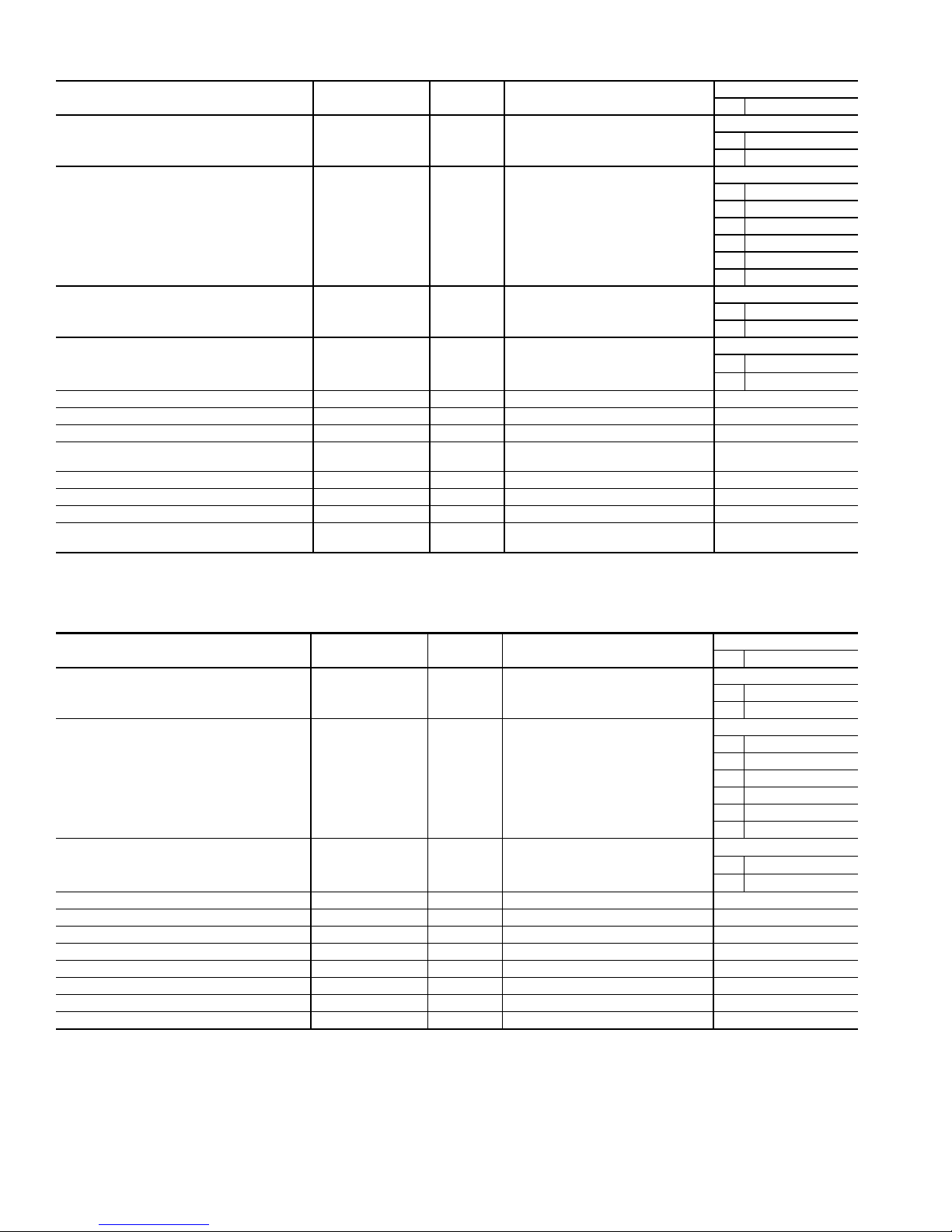
Table 8 — Fan Board A Outputs (30XA080-122)
DESCRIPTION INPUT/OUTPUT I/O TYPE DISPLAY MODULE POINT NAME
Power (24 vac supply) —— —
Local Equipment Network —— —
Circuit A Low Ambient Temperature
Head Pressure Control Speed Signal
Circuit B Low Ambient Temperature
Head Pressure Control Speed Signal
Fan Contactor A1 FCA1 Contactor FBA-J2-CH1
Fan Contactor A2 FCA2 Contactor FBA-J2-CH2
Fan Contactor A3 FCA3 Contactor FBA-J2-CH3
Fan Contactor A4 FCA4 Contactor
Fan Contactor B1 FCB1 Contactor FBA-J3-CH5
Fan Contactor B2 FCB2 Contactor FBA-J3-CH6
Fan Contactor B3 FCB3 Contactor FBA-J3-CH7
Fan Contactor B4 FCB4 Contactor
*Output only on low ambient temperature head pressure control (AUX1).
MM-A* 0-10 VDC Head Press Actuator Pos, SPD.A
MM-B* 0-10 VDC Head Press Actuator Pos, SPD.B
CONNECTION POINT
Pin Notation
FBA-J1
11 24 vac
12 Ground
FBA-J9
+ RS485 Port (D+)
G RS485 Port (Gnd)
-RS485 Port (D-)
+ RS485 Port (D+)
G RS485 Port (Gnd)
-RS485 Port (D-)
FBA-CH9
+ Signal
- Ground
FBA-CH10
+ Signal
- Ground
FBA-J2-CH4
(090-122)
FBA-J3-CH8
(090-122)
Table 9 — Fan Board X Outputs (30XA140-352)
DESCRIPTION INPUT/OUTPUT I/O TYPE DISPLAY MODULE POINT NAME
Power (24 vac supply) —— —
Local Equipment Network —— —
Circuit X Low Ambient Temperature
Head Pressure Control
Speed Signal
Fan Contactor X1 FCX1 Contactor FBX-J2-CH01
Fan Contactor X2 FCX2 Contactor FBX-J2-CH02
Fan Contactor X3 FCX3 Contactor FBX-J2-CH03
Fan Contactor X4 FCX4 Contactor FBX-J2-CH04
Fan Contactor X5 FCX5 Contactor FBX-J3-CH05
Fan Contactor X6 FCX6 Contactor FBX-J3-CH06
Fan Contactor X7
Fan Contactor X8 FCX8 Contactor FBX-J3-CH08
*Output only on units with low ambient temperature head pressure control installed (AUX1).
NOTES:
1. Fan Board B used on 30XA140-350.
2. “X” indicates circuit A or circuit B.
3. See page 109, Fig. 65 for which contactor is used with circuit A
or B.
MM-n* 0-10 VDC Head Press Actuator Pos, SPD.X
FCX7 Contactor FBX-J3-CH07
CONNECTION POINT
Pin Notation
FBX-J1
11 24 vac
12 Ground
FBX-J9
+ RS485 Port (D+)
G RS485 Port (Gnd)
- RS485 Port (D-)
+ RS485 Port (D+)
G RS485 Port (Gnd)
- RS485 Port (D-)
FBX-CH9
+ Signal
- Ground
16
Page 17
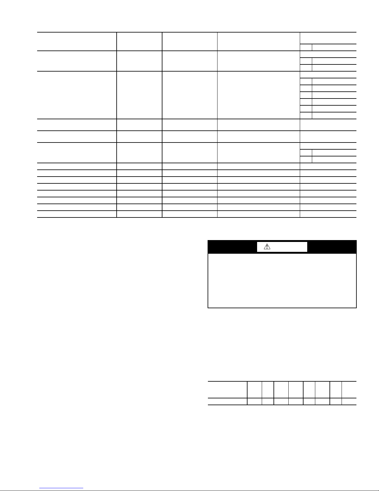
Table 10 — Fan Board C Inputs and Outputs (30XA400-500)
DESCRIPTION INPUT/OUTPUT I/O TYPE DISPLAY MODULE POINT NAME
Power (24 vac supply) —— —
Local Equipment Network —— —
Circuit C Discharge
Pressure Transducer
Circuit C Suction
Pressure Transducer
Circuit C Low Ambient
Temperature Head Pressure
Control Speed Signal
Fan Contactor C1 FCC1 Contactor FBC-J2-CH1
Fan Contactor C2 FCC2 Contactor FBC-J2-CH2
Fan Contactor C3 FCC3 Contactor FBC-J2-CH3
Fan Contactor C4 FCC4 Contactor FBC-J2-CH4
Fan Contactor C5 FCC5 Contactor FBC-J3-CH5
Fan Contactor C6 FCC6 Contactor FBC-J3-CH6
Fan Contactor C7 FCC7 Contactor FBC-J3-CH7
Fan Contactor C8 FCC8 Contactor FBC-J3-CH8
DPTC Pressure Transducer Discharge Pressure, DP.C FBC-J7-CH13
SPTC Pressure Transducer Suction Pressure, SP.C FBC-J8-CH14
MM-C 0-10 VDC Head Press Actuator Pos, SPD.C
CONNECTION POINT
Pin Notation
11 24 vac
12 Ground
+ RS485 Port (D+)
G RS485 Port (Gnd)
- RS485 Port (D-)
+ RS485 Port (D+)
G RS485 Port (Gnd)
- RS485 Port (D-)
+ Signal
- Ground
(Unit Size)
FBC-J1
FBC-J9
FBC-CH9
Enable-Off-Remote Contact Switch (SW1) —
This switch is installed in all units and provides the owner and
service person with a local means of enabling or disabling the
machine. It is a 3-position switch and it is used to control the
chiller. When switched to the Enable position, the chiller will
be under its own control. When switched to the Off position,
the chiller will shut down. When switched to the Remote Contact position, a field-installed dry contact can be used to start
the chiller. The contacts must be capable of handling a 24-vac,
50-mA load. In the Enable and Remote Contact (dry contacts
closed) positions, the chiller is allowed to operate and respond
to the scheduling configuration, CCN configuration, and set
point data.
For units with a Touch Pilot™ display, the position of the
Enable/Off/Remote contact switch is ignored except when the
“remote mode” control type is selected. Refer to the Machine
Control Methods section on page 22 for more details.
Emergency On/Off Switch (SW2) — This switch is
installed in all units. The Emergency On/Off switch should
only be used when it is required to shut the chiller off immediately. Power to all modules is interrupted when this switch is
off and all outputs from these modules will be turned off.
Energy Management Module (EMM) — The EMM
is available as a factory-installed option or as a field-installed
accessory. See Fig. 13. The EMM receives 4 to 20 mA inputs
for the temperature reset, cooling set point and demand limit
functions. The EMM also receives the switch inputs for the
field-installed second stage 2-step demand limit and ice done
functions. The EMM communicates the status of all inputs
with the MBB, and the MBB adjusts the control point, capacity
limit, and other functions according to the inputs received. See
Tab l e 11.
CAUTION
Care should be taken when interfacing with other manufacturer’s control systems due to possible power supply differences, full wave bridge versus half wave rectification,
which could lead to equipment damage. The two different
power supplies cannot be mixed. ComfortLink™ controls
use half wave rectification. A signal isolation device should
be utilized if incorporating a full wave bridge rectifier signal generating device is used.
Hot Gas Bypass/Pump Board — The hot gas by-
pass (HGBP) and pump board controls the ON/OFF of the
HGBP solenoids and pump contactors, and responds to MBB
commands via the LEN connection. Hot gas bypass is available as a factory-installed option or as a field-installed accessory for 30XA080-500, and the pump package is available as
factory-installed option for sizes 30XA090-162. See Fig. 14.
The board is not required for single pump operation. See below
for DIP switch information. See Table 12 for HGBP/Pump
board inputs and outputs.
HGBP/Pump
BOARD
DIP SWITCH
Address: ON ON ON OFF ON OFF ON OFF
123 45678
17
Page 18
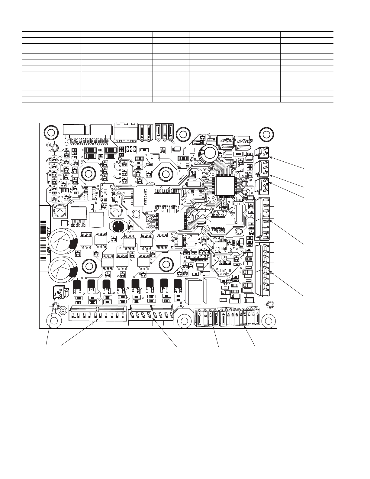
Table 11 — Energy Management Module (EMM) Inputs and Outputs
221
221
221
221
100K
100K
100K
100K
100K
CH
17
CH
17
CH
16
CH
CH
18
CH
19
CH
20
CH
22
CH
21
CH
23
24 VAC
12 11
CH
11b
CH
12
CH
13
CH
14
CH
15
CH
1
CH
2
CH
3
CH
4
CH 5
CH 6
CH 7
SIO LEN
+ G -
+ G -
SIO LEN
J8
J7B
J7A
J6
J5
J4 J3 J2B
J2A
J1
Fig. 13 — Energy Management Module
a30-4465
INPUT/OUTPUT DESCRIPTION I/O TYPE DISPLAY MODULE POINT NAME CONNECTION POINT
4-20 mA Demand Limit 4-20 mA Demand Limit 4-20 mA* Limit 4-20 mA Signal, DMD EMM-J7B-CH6
4-20 mA Temperature
Reset/Cooling Setpoint
Demand Limit SW2 Demand Limit Step 2 Switch Input Switch Limit Setpoint 2, DLS2 EMM-J4-CH9
Ice Done Ice Done Switch Switch Input Ice Done Storage Switch, ICE.D EMM-J4-CH11A
Occupancy Override Occupied Schedule Override Switch Input Occupied Override Switch, OCCS EMM-J4-CH8
Remote Lockout Switch Chiller Lockout Switch Input Remote Interlock Switch, RLOC EMM-J4-CH10
SPT Space Temperature Thermistor 10k Thermistor Optional Space Temp, SPT EMM-J6-CH2
% Total Capacity Percent Total Capacity Output 0-10 vdc Chiller Capacity Signal, CATO EMM-J8-CH7
RUN R Run Relay Relay Running Status, RUN EMM-J3-CH25
SHD R Shutdown Relay Relay Shutdown Indicator State, SHUT EMM-J3-CH24
* A field-supplied 1/2 watt 250 ohm resistor is required across terminals TB6-1,2 (CH6) and/or TB6-3, 4 (CH5).
4-20 mA Temperature Reset/
Cooling Set point
4-20 mA*
Reset/Setpnt 4-20 mA Signal, RSET
EMM-J7A-CH5
18
Page 19
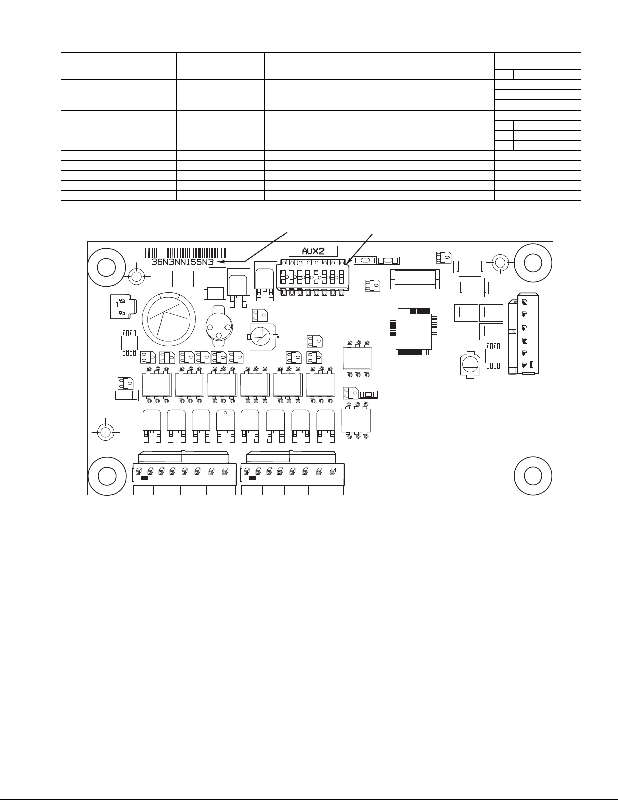
Table 12 — Hot Gas Bypass/Pump Board Inputs and Outputs
1
2
3
4
5
6
7
8
ON
100K
100K
100K
LOCATION OF
SERIAL NUMBER
TB1 TB2 TB3 TB4 TB5 TB6 TB7 TB8
CH1 CH2 CH3 CH4 CH5 CH6 CH7 CH8
STATUS SIO (LEN)
24 VAC
J1
J9
D4
U2
U5
Q2
Q7
Q3
U8
U9
Q9
Q10
Q11Q12
Q13
J4
J3
J2
S1
D7
Q5
Y1
D5
D6
L2
U6
U1
Q1
D3
C3
3 2 1
– G +
3 2 1
– G +
DIP SWITCH
Fig. 14 — Hot Gas Bypass/Pump Board
a30-4047
DESCRIPTION INPUT/OUTPUT I/O TYPE DISPLAY MODULE POINT NAME
—— — HGBP/PMP-J1
Power (24 vac supply)
—— — HGBP/PMP-J9
Local Equipment Network
Circuit A Minimum Load Control MLV-A Solenoid Valve Hot Gas Bypass A Output, HGB.A HGBP/PMP-J2-CH3
Circuit B Minimum Load Control MLV-B Solenoid Valve Hot Gas Bypass B Output, HGB.B HGBP/PMP-J2-CH4
Circuit C Minimum Load Control MLV-C Solenoid Valve Hot Gas Bypass C Output, HGB.C HGBP/PMP-J2-CH5
Pump #1 Starter PMP1 Contactor Water Exchanger Pump 1, PMP.1 HGBP/PMP-J2-CH1
Pump #2 Starter PMP2 Contactor Water Exchanger Pump 2, PMP.2 HGBP/PMP-J2-CH2
CONNECTION POINT
Pin Notation
11 24 vac
12 Ground
+ RS485 Port (D+)
G RS485 Port (Gnd)
- RS485 Port (D-)
Local Equipment Network — Information is trans-
mitted between modules via a 3-wire communication bus or
LEN (Local Equipment Network). External connection to the
LEN bus is made at TB3.
Board Addresses — All boards (except the Main Base
Board and Energy Management Module Board) have
8-position DIP switches.
Touch Pilot™ Display — The Touch Pilot display port
connections are shown in Table 13. Wiring is shown in Fig. 15.
Control Module Communication
RED LED — Proper operation of the control boards can be
visually checked by looking at the red status LEDs (lightemitting diodes). When operating correctly, the red status
LEDs will blink in unison at a rate of once every 2 seconds. If
the red LEDs are not blinking in unison, verify that correct
power is being supplied to all modules. Be sure that the Main
Base Board (MBB) is supplied with the current software. If
necessary, reload current software. If the problem still persists,
replace the MBB. A red LED that is lit continuously or blinking at a rate of once per second or faster indicates that the board
should be replaced.
GREEN LED — All boards have a green LEN (SIO) LED
which should be blinking whenever power is on. If the LEDs
are not blinking as described check LEN connections for
potential communication errors at the board connectors. See
Input/Output Tables 3-12 for LEN connector designations. A
3-wire bus accomplishes communication between modules.
These 3 wires run in parallel from module to module. The J9A
connector on the MBB provides communication directly to the
Navigator™ display module.
YELLOW LED — The MBB has one yellow LED. The
Carrier Comfort Network
®
(CCN) LED will blink during times
of network communication.
19
Page 20
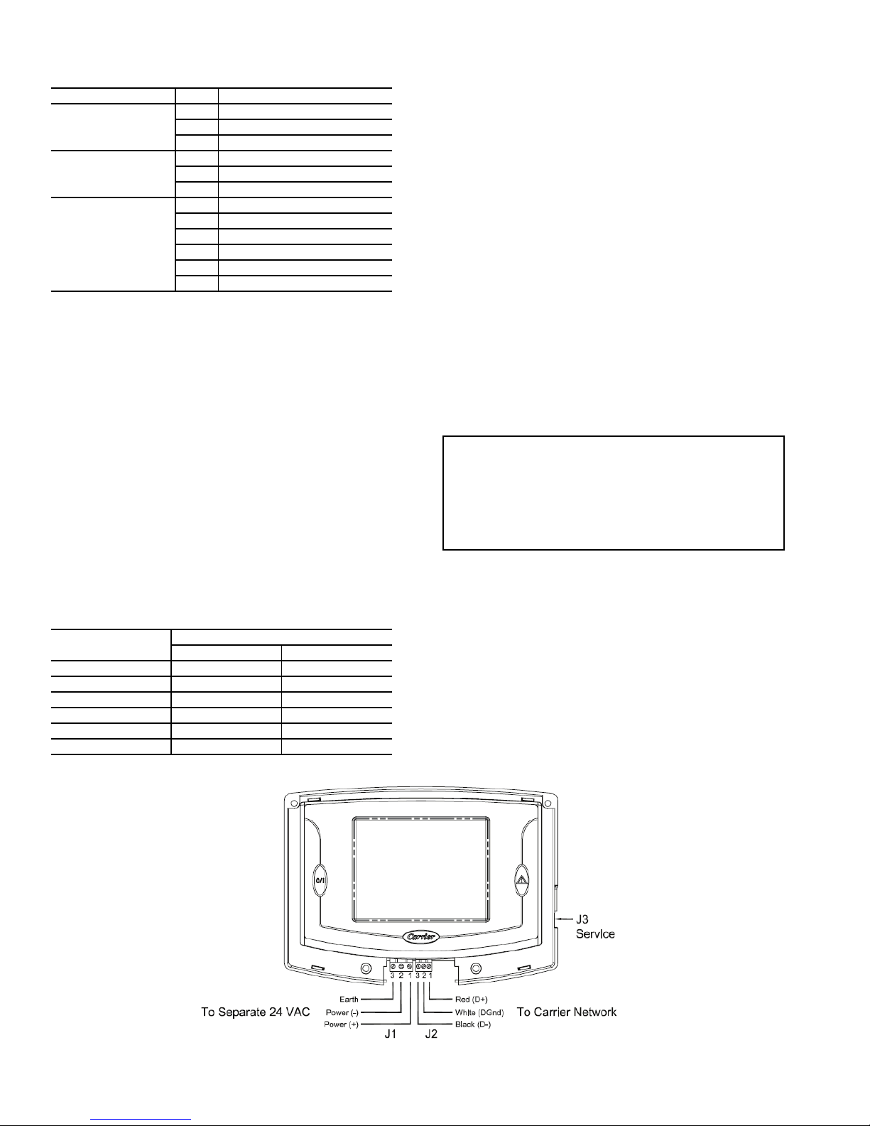
Table 13 — Touch Pilot™ Display Port
a30-4082
Fig. 16 — ComfortLink™ CCN Communication Wiring
Fig. 15 — Touch Pilot™ Display Wiring
Connections
CONNECTOR PIN FUNCTION
1 24VAC +
J1 (Power)
J2 (COM1)
J3 (RJ11)
2 24VAC 3 Earth Ground
1 RS485 Port (D+)
2 RS485 Port (GND)
3 RS485 Port (D-)
1 24VAC (+)
2 RS485 Port (D+)
3 RS485 Port (GND)
4 Unused (no connect)
5 RS485 Port (D-)
6 24VAC(-)
Carrier Comfort Network® (CCN) Interface —
All 30XA units can be connected to the CCN, if desired. The
communication bus wiring is a shielded, 3-conductor cable
with drain wire and is field supplied and installed. The system
elements are connected to the communication bus in a daisy
chain arrangement. The positive pin of each system element
communication connector must be wired to the positive pins of
the system elements on either side of it. The negative and signal ground pins of each system element must also be wired in
the same manner. Wiring connections for CCN should be made
at TB3. Consult the CCN Contractor’s Manual for further information. See Fig. 16.
NOTE: Conductors and drain wire must be 20 AWG (American Wire Gage) minimum stranded, tinned copper. Individual
conductors must be insulated with PVC, PVC/nylon, vinyl,
Teflon, or polyethylene. An aluminum/polyester 100% foil
shield and an outer jacket of PVC, PVC/nylon, chrome vinyl,
or Teflon with a minimum operating temperature range of
–20 C to 60 C is required. See Table 14 for recommended wire
manufacturers and part numbers.
Table 14 — CCN Communication Bus Wiring
MANUFACTURER
Alpha 1895 —
American A21451 A48301
Belden 8205 884421
Columbia D6451 —
Manhattan M13402 M64430
Quabik 6130 —
Regular Wiring Plenum Wiring
PART NU M B E R
It is important when connecting to a CCN communication
bus that a color-coding scheme be used for the entire network
to simplify the installation. It is recommended that red be used
for the signal positive, black for the signal negative, and white
for the signal ground. Use a similar scheme for cables containing different colored wires.
At each system element, the shields of its communication
bus cables must be tied together. If the communication bus is
entirely within one building, the resulting continuous shield
must be connected to a ground at one point only. If the communication bus cable exits from one building and enters another,
the shields must be connected to grounds at the lightning
suppressor in each building where the cable enters or exits the
building (one point per building only). To connect the unit to
the network:
1. Turn off power to the control box.
2. Cut the CCN wire and strip the ends of the red (+), white
(ground), and black (–) conductors. (Substitute appropriate colors for different colored cables.)
3. Connect the red wire to (+) terminal on TB3 of the plug,
the white wire to COM terminal, and the black wire to the
(–) terminal.
4. The RJ14 CCN connector on TB3 can also be used, but is
only intended for temporary connection (for example, a
laptop computer running Service Tool).
IMPORTANT: A shorted CCN bus cable will prevent
some routines from running and may prevent the unit
from starting. If abnormal conditions occur, disconnect the CCN bus. If conditions return to normal,
check the CCN connector and cable. Run new cable if
necessary. A short in one section of the bus can cause
problems with all system elements on the bus.
Remote Alarm and Alert Relays — The 30XA chill-
er can be equipped with a remote alert and remote alarm
annunciator contacts. Both relays connected to these contacts
must be rated for a maximum power draw of 10 va sealed,
25 va inrush at 24 volts. The alarm relay, indicating that the
complete unit has been shut down, can be connected to TB5-12
and TB5-13. Refer to unit wiring diagrams. For an alert relay,
indicating that at least 1 circuit is off due to the alert, a fieldsupplied and installed relay must be connected between MBBJ3-CH25-3 and TB5-13. The action of the alarm and alert relays can be reversed from normally open to normally closed by
using the Reverse Alarms Relay configuration (Reverse
Alarms Relay, RV.AL).
20
Page 21
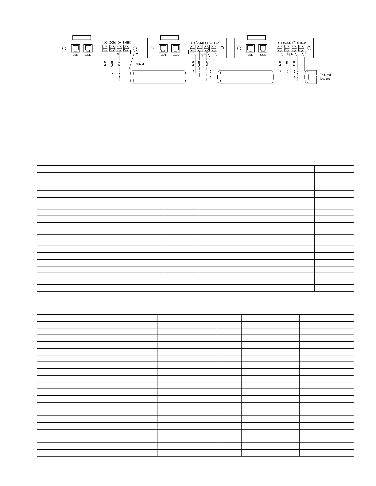
CONFIGURATION
Fig. 16 — ComfortLink™ CCN Communication Wiring
Touch Pilot™ Operation Configuration
Table s —
configuration information entered in the following configuration tables. These tables are accessible by using Network
The Touch Pilot display operation is controlled by
Service Tool or ComfortVIEW™ software. The tables are the
CtrlID (Controller Identification) configuration table and the
USERCONF (User Configuration) table. See Tables 15 and 16.
NOTE: Always perform an Upload to obtain the latest configuration before making configuration table changes.
Table 15 — Touch Pilot Controller Identification Configuration Table
CONTROLLER ID DATA BLOCK NO. VALUE AND RANGE QUALIFIERS
Device Name 1
Local address 2 115 Default
Bus number 2 0 Default
Device (driver) type 2
Primary baud rate 3 38400 Default
Secondary baud rate 3 38400 Fixed
Device description 4
Device location 4
Software part number 4 CESR-131363-01 Fixed
Model number 4 (Blank) Fixed
Serial number 4 (Blank) Fixed
Reference number 4 Version 1.0 Fixed
Broadcast address processing list (primary) 5
Broadcast address processing list (secondary) 5 none Not applicable
CHILLDSP
8 character Name field
0 = Non-bridge
3 = Broadcast Acknowledger
Global Chiller Display
24 character text field
(Blank)
24 character text field
241-251, 254, 255 enabled
241-255 enabled/disabled
Default
Optional
Default
Optional
Default
Optional
Default
Optional
Defaults
Optional
Table 16 — Touch Pilot™ User Configuration (USERCONF) Table
DESCRIPTION LIMITS UNITS NAME DEFAULT
Backlight always on? No - Yes BACKLITE No
Full access password 0 - 9999 PSWDFULL 3333
Limited access password 0 - 9999 PSWDLMTD 2222
Active language 0 - 1 ACTLANG 0
Time format 0 - 1 TIMEFMT 0
Date format 0 - 2 DATEFMT 0
Units base US - Metric UNITBASE US
Contrast control Manual - Auto CONTRAST Auto
Network mode 0 - 1 NETWORK 0
Network settings
Alarm acknowledger No - Yes ALARMACK No
Broadcast acknowledger No - Yes BROADACK No
Equipment CCN address
Bus number 0 - 239 EQUIPBUS 0
Element number 1 - 239 EQUIPELE 1
Control variables
Equipment status (Not Used) Name char 8 EQSTATUS NOT USED
Equipment start/stop (Not Used) Name char 8 STARSTOP NOT USED
Alarm status (Not Used) Name char 8 ALSTATUS NOT USED
Alarm reset (Not Used) Name char 8 ALRESET NOT USED
21
Page 22

BACKLIGHT ALWAYS ON? — This configuration is used
to keep the backlight on continuously or to turn it off after 60
seconds with no activity.
Allowable Entries: No/Yes (No=0 or Yes=1)
Default Value: No
FULL ACCESS PASSWORD — This configuration is used
to specify the full access password. Refer to Table 1, Setup
Menu, for additional information on passwords.
Allowable Entries: 0 through 9999
Default Value: 3333
LIMITED ACCESS PANEL — This configuration is used to
specify the limited access password.
Allowable Entries: 0 through 9999
Default Value: 2222
ACTIVE LANGUAGE — This configuration is used to spec-
ify the display’s active language. All translatable text will be
displayed in this language.
Allowable Entries: 0, 1
Default Value: 0
TIME FORMAT — This configuration is used to specify the
format for display of time.
Allowable Entries: 0 = H:MM AM/PM without leading zero
1 = HH:MM with leading zero when
necessary
Default Value: 0
DATE FORMAT — This configuration is used to specify the
format for display of date.
Allowable Entries: 0 = MM-DD-YYYY with leading zero
when necessary
1 = DD-MM-YYYY with leading zero
when necessary
2 = YYYY-MM-DD
Default Value: 0
UNITS BASE — This configuration is used to specify the for-
mat of the units of measure.
Allowable Entries: U.S.
Metric
Default Value: U.S.
CONTRAST CONTROL — This configuration is used to en-
able or disable the display’s auto contrast adjustment feature.
When enabled, the display’s contrast will be automatically adjusted as required, based on temperature.
Allowable Entries: Manual
(Auto Contrast Adjustment Disabled)
Auto
(Auto Contrast Adjustment Enabled)
Default Value: Auto
NETWORK MODE — This configuration is used to set the
display’s operating mode. For additional information on operating mode, refer to Display in the Table Setup Menu. This decision will be ignored and the mode will default to Equipment
when the display is connected to a device (the LEN Bus).
NOTE: A power cycle is required for this decision to take
effect.
Allowable Entries: 0 (Disable) = Equipment Mode
1 (Enable) = Network Mode
Default Value: 0 (Disable)
ALARM ACKNOWLEDGER — This configuration is used
to specify whether the Touch Pilot™ display will act as the
alarm acknowledger for the CCN. There can be only one alarm
acknowledger per CCN. Therefore, if another CCN device
such as ComfortVIEW™ software, the Autodial Gateway or
TeLINK is already set as the alarm acknowledger for the CCN
network then this decision should be set to No.
NOTE: The display must be in Network mode and connected
to the primary CCN bus and this decision set to Ye s for alarm
acknowledgement to be enabled.
Allowable Entries: No
Ye s
Default Value: No
BROADCAST ACKNOWLEDGER — This configuration
is used to indicate whether the Touch Pilot display will act as
the broadcast acknowledger for its CCN bus. There can be only
one broadcast acknowledger per CCN bus.
NOTE: The display must be in Network mode and this decision set to Ye s for broadcast acknowledgement to be enabled.
Allowable Entries: No
Ye s
Default Value: No
EQUIPMENT CCN ADDRESS — When in equipment
mode (USERCONF Table’s Network Mode decision is set to
Disable), the Bus Number and Element Number decisions are
used to specify the CCN address of the piece of equipment to
communicate with. An Attach or power cycle must be
performed for changes to take effect. These decisions will be
ignored when the display is connected to the LEN bus or in
Network mode. In Network mode, specify the bus and element
number the equipment communicates with using the display’s
Attach function.
NOTE: In Network mode, these configurations will be overwritten with the default device address if it is changed through
the Attach process.
BUS NUMBER — This configuration is used to specify the
Equipment Controller bus number.
Allowable Entries: 0 through 239
Default Value: 0
ELEMENT NUMBER — This configuration is used to speci-
fy the Equipment Controller element number.
Allowable Entries: 1 through 239
Default Value: 1
Machine Control Methods — Three variables con-
trol how the machine operates. These variables control the
On-Off function, set point operation, and Heat-Cool operation.
Machine On/Off Control — Machine On/Off control
depends on which interface display is used. The control is different for Touch Pilot™ or Navigator™ displays. Select the
correct configuration procedure below based on which interface is being used.
TOUCH PILOT MACHINE CONTROL — Machine On/Off
control is determined locally by pushing the Start/Stop button
on the Touch Pilot display. Pressing this button will cause the
Equipment Start screen to be displayed. See Fig. 17.
Table 17 summarizes the unit control type and stop or go
status with regard to the following parameters:
• Operating type: this is selected by using the start/stop button
on the front of the user interface.
• Remote start/stop contacts: these contacts are used when the
unit is in remote operating type (Remote mode).
• CHIL_S_S: this network command variable relates to the
chiller start/stop when the unit is in CCN control (CCN
mode). When this variable forced to Disable, then the unit is
stopped. When this variable is forced to Enable, then the
unit runs in accordance with schedule 1.
22
Page 23
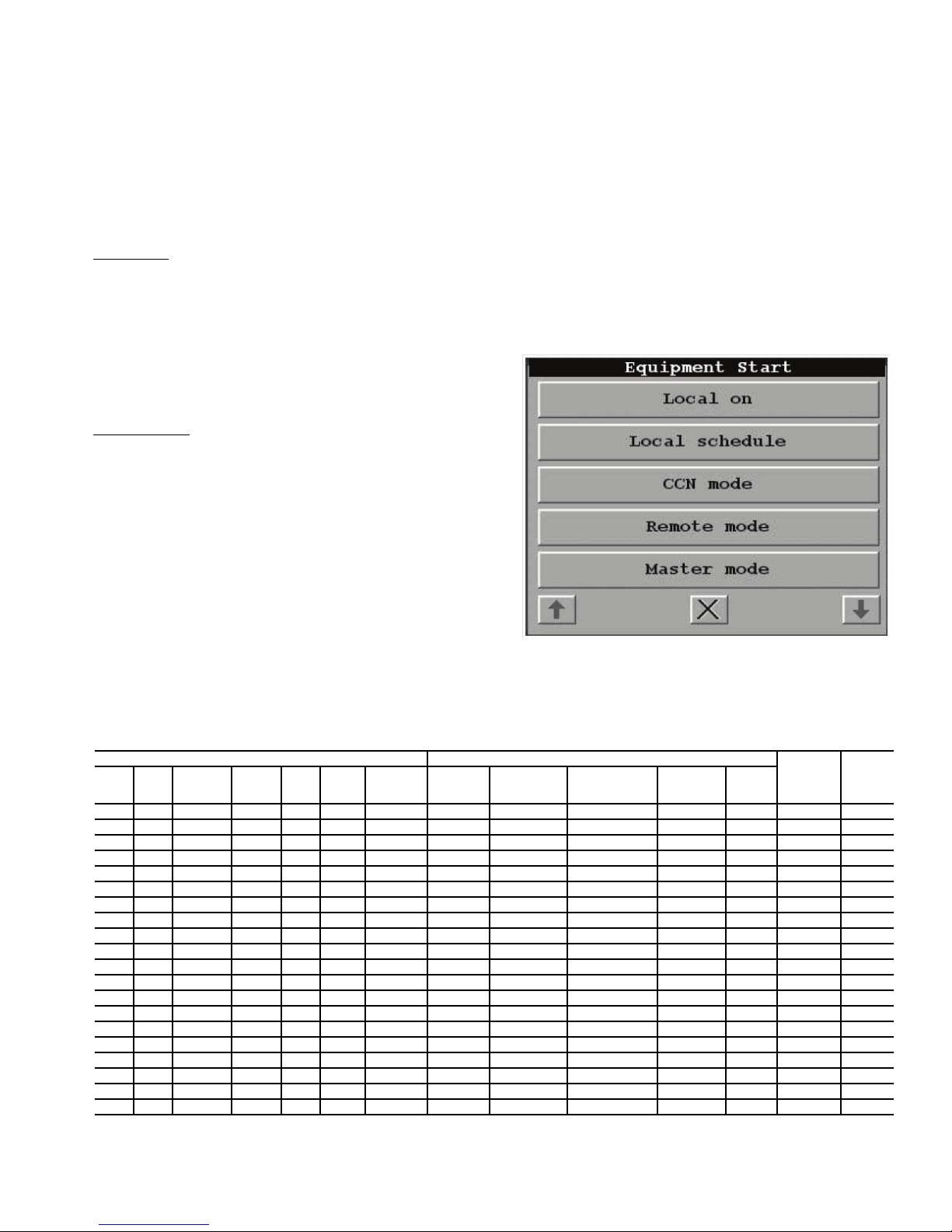
• Start/Stop schedule: occupied or unoccupied status of the
Fig. 17 — Equipment Start Screen
unit as determined by the chiller start/stop program (Schedule 1).
• Master control type: This parameter is used when the unit is
the master unit in a two chiller lead/lag arrangement. The
master control type determines whether the unit is to be
controlled locally, remotely or through CCN (this parameter
is a Service configuration).
• CCN emergency shutdown: if this CCN command is activated, it shuts the unit down whatever the active operating
type.
• General alarm: the unit is totally stopped due to failure.
Local Mode
— To start the machine in local mode, press the
Start/Stop button on the Touch Pilot display. The Equipment
Start screen will be displayed. Select Local On. The control
will ignore the position of Enable/Off/Remote Contact switch
and all CCN network force commands, except an Emergency
Stop Command. The Run Status variable, indicating the cur-
rent status of the machine, will change to RUNNING, DELAY
or READY. The Chiller Occupied? variable will change to
YES. The Control Type variable indicates the type of control.
For this configuration, Control Type will be Local. The Oper-
ating Type variable will change to L-On (Local On).
Local Schedule
— To start the machine with a local schedule,
press the Start/Stop button on the Touch Pilot display. The
Equipment Start screen will be displayed. Select Local Schedule. The unit will start and stop according to the schedule defined in the Time Schedule menu. Two Internal Time Schedules are available and must be field programmed. Time
Schedule 1 is used for single set point On-Off control. Time
Schedule 2 is used for Dual Set Point/Occupied-Unoccupied set point control. The control will ignore the position of
Enable/Off/Remote Contact switch and all CCN network force
commands, except the Emergency Stop Command.
The Run Status variable will indicate the current status of
the machine — OFF, RUNNING, DELAY, or READY. The
Chiller Occupied? variable will indicate the occupied state of
the machine according to Time Schedule 1 and will be either
YES (occupied) or NO (unoccupied). The Control Type vari-
able will indicate the type of control. For this configuration,
Control Type will be Local. The Operating Type variable
will change to L-Sched (Local Schedule).
The schedules consist of 8 user-configurable occupied time
periods. The control supports time schedules for local control,
remote control, and ice building. These time periods can be
flagged to be in effect or not in effect on each day of the week.
The day begins at 00.00 and ends at 24.00. The machine will be
in unoccupied mode unless a scheduled time period is in effect.
If an occupied period extends past midnight, the occupied
period will automatically end at 24:00 hours (midnight) and the
new occupied period must be programmed to begin at 00:00
hours.
In the following example, the occupied period starts at 6:00
AM, Monday through Friday and 10:00 AM on Saturday and
Sunday. The occupied time ends at 6:30 PM on Monday
through Friday and 2:00 PM on Saturday and Sunday. See
Fig. 18.
Table 17 — Touch Pilot™ Start/Stop Control
ACTIVE OPERATING TYPE PARAMETER STATUS
LocalOnLocalOnLocal
-- - - - - - - - - Active - - Off
-- - - - - - - - - - Yes - Off
Active - - - - - - - - - - - Local Off
- - Active - - - - - - Unoccupied - - Local Off
- - - Active - - - Off - - - - Remote Off
- - - Active - - - - - Unoccupied - - Remote Off
- - - - Active - Off - - - - - CCN Off
- - - - Active - - - - - - - CCN Off
- - - - - Active - - Local Unoccupied - - Local Off
- - - - - Active - Off Remote - - - Remote Off
- - - - - Active - - Remote Unoccupied - - Remote Off
- - - - - Active Off - CCN - - - CCN Off
- - - - - Active - - CCN Unoccupied - - CCN Off
- Active - - - - - - - - Disabled No Local On
- - Active - - - - - - Occupied Disabled No Local On
- - - Active - - - On Cool - Occupied Disabled No Remote On
- - - - Active - On - - Occupied Disabled No CCN On
- - - - - Active - - Local Occupied Disabled No Local On
- - - - - Active - On Cool Remote Occupied Disabled No Remote On
- - - - - Active On - CCN Occupied Disabled No CCN On
Schedule
Remote
Mode
CCN
Mode
Master
Mode
CHIL_S_S
Varia ble
Remote
Start/Stop
Contact
Master Unit
Control Type
Start/Stop
Schedule
Mode
CCN
Emergency
Shutdown
General
Alarm
CONTROL
TYPE
UNIT
STATUS
23
Page 24
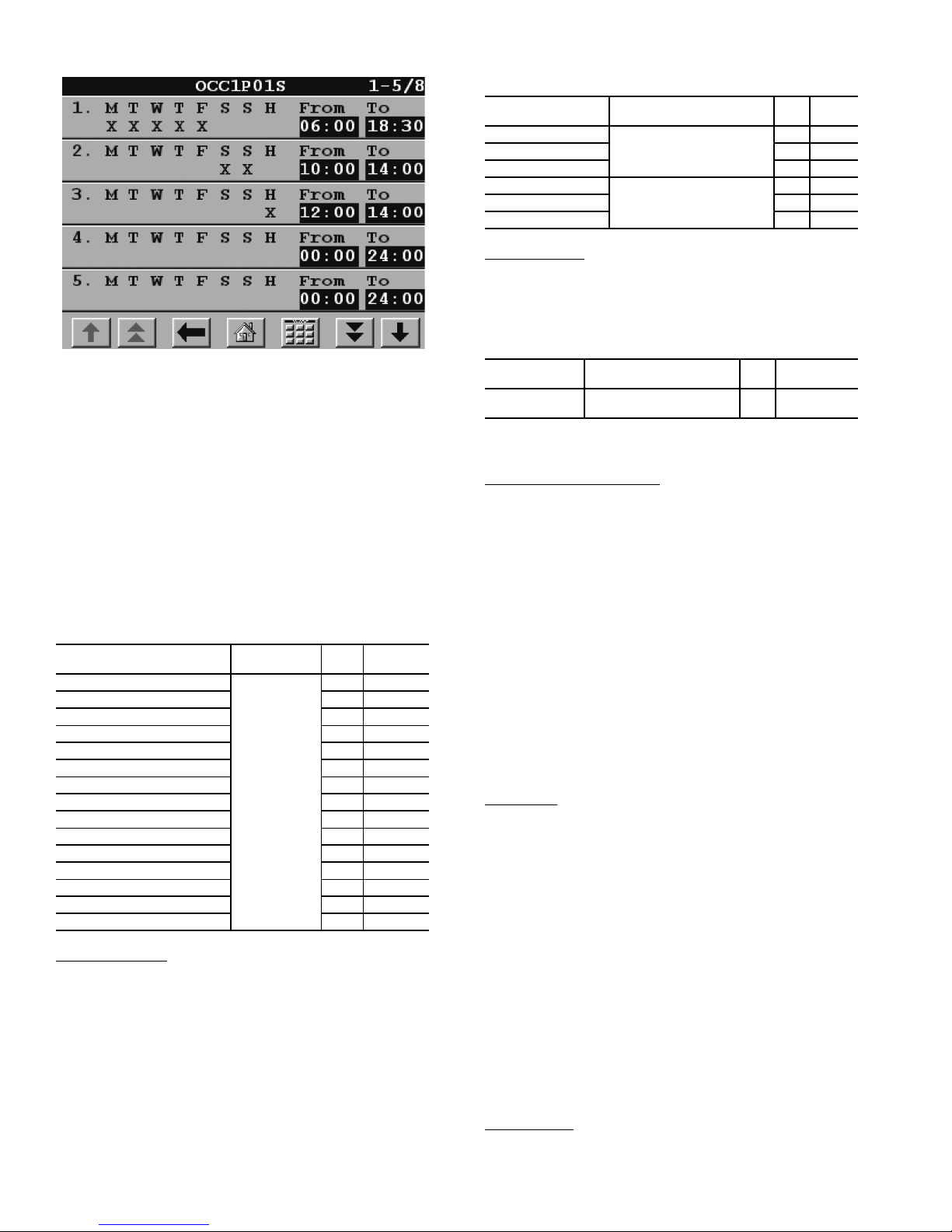
Table 19 — Programming Holiday Schedules with
Fig. 18 — Chiller Schedule Screen
Touch Pilot Display
NOTE: This schedule was designed to illustrate the programming of the schedule function and is not intended as a
recommended schedule for chiller operation.
If the chiller is to be controlled to a single set point, use
Schedule 1 (OCCPC01S). This will start and stop the machine.
During the unoccupied times, the chiller will be off. If the chiller is to be controlled to 2 set points, occupied and unoccupied,
use Schedule 2 (OCCPC02S). This will cause the chiller to
control to an occupied set point and an unoccupied set point.
The machine will be able to provide cooling at any time.
To configure this option on the Touch Pilot™ display see
Table 18.
Table 18 — Configuring the Schedule with
Touch Pilot Display
DISPLAY NAME PATH
Period 1 DOW (MTWTFSSH)
Occupied from 3 00:00
Occupied to 4 03:00
Period 2 DOW (MTWTFSSH) 5 11000000
Occupied from 6 07:00
Occupied to 7 18:00
Period 3 DOW (MTWTFSSH) 8 00100000
Occupied from 9 07:00
Occupied to 10 21:30
Period 4 DOW (MTWTFSSH) 11 00011000
Occupied from 12 07:00
Occupied to 13 17:00
Period 5 DOW (MTWTFSSH) 14 00000100
Occupied from 15 07:00
Occupied to 16 12:00
Holiday Schedule
— For the Touch Pilot display, the control
Config\
OCCDEFCS\
OCC1P01S
or OCC1P02S
LINE
VAL UE
NO.
2 10000000
allows up to 16 holiday periods. All holidays are entered with
numerical values. To configure, first change the month (Holi-
day Start Month), then the day (Holiday Start Day), then the
duration (Holiday Duration) of the holiday period in days. If a
holiday in included in one of the Occupied Time Periods of the
schedule, the machine will follow that operating condition for
the holiday. In the following examples, the holidays July 4 and
December 25-26 are programmed for Holiday 1 and Holiday 2,
respectively. To configure these holidays with the Touch Pilot
display, see Table 19. To configure Holidays with the Navigator display, check the H (holiday) schedule on the Schedule
screen and program in the desired occupied times. See Fig. 18.
DISPLAY NAME PATH
Holiday Start Month
Start Day 24
Duration (days) 31
Holiday Start Month
Start Day 225
Duration (days) 32
Timed Override
Config\HOLIDAY\HOLDY_01
Config\HOLIDAY\HOLDY_02
— With the Touch Pilot display only, each
LINE
VAL UE
NO.
17
112
time schedule can be overridden to keep the chiller in an Occupied mode (Timed Override Hours) for 1, 2, 3 or 4 hours on a
one-time basis. To configure this option for the Touch Pilot display, see Table 20.
Table 20 — Configuring Timed Override
DISPLAY NAME PATH
Timed Override
Hours
Config\OCCDEFCS\
OCC1P01S or OCC1P02S
LINE
NO.
1
VAL UE
Range: 0 to 4
Default: 0
If configured for a timed override, the override can be can-
celled by changing the Timed Override Hours to 0.
CCN Global Time Schedule
— A CCN Global Schedule can
be utilized with the chiller controls. The schedule number can
be set anywhere from 65 to 99 to configure operation under a
CCN global schedule. The 30XA chillers can be configured to
follow a CCN Global Time Schedule broadcast by another system element. ComfortVIEW™ Network Manager’s Configure
and Modify commands or the Service Tool’s Modify/Names
function must be used to change the number of the Occupancy
Equipment Part Table Name (OCC1P01E) to the Global
Schedule Number. The Schedule Number can be set from 65 to
99 (OCC1P65E to OCC1P99E).
The Occupancy Supervisory Part table name (OCC1P01S)
number must be changed to configure the unit to broadcast a
Global Time Schedule. The Schedule Number can be set from
65 to 99 (OCC1P65S to OCC1P99S). When OCC1PxxS is set
to a value greater than 64, an occupancy flag is broadcast over
the CCN every time it transitions from occupied to unoccupied
or vice-versa. By configuring their appropriate Time Schedule
decisions to the same number, other devices on the network can
follow this same schedule.
CCN Mode
— To allow machine control by CCN commands,
press the Start/Stop button on the Touch Pilot™ display. The
Equipment Start screen will be displayed. Select CCN Mode.
The unit will be controlled by a CCN command to the CCN
Chiller Star t/Stop variable. An external CCN device, such as
Chillervisor, controls the On/Off state of the machine. When
controlled by a Chillervisor, it is recommended that the Auto
Start W hen SM Lost configuration be set to Yes. In the event
of a loss of communication with the network, the machine will
start and be controlled locally.
Careful evaluation of chilled water plant control should be
reviewed. In the event local control is established, be sure that
all pumps, valves, and other devices are capable of operating
properly. The control will ignore the position of Enable/Off/
Remote Contact switch. The Run Status variable will indicate
the current status of the machine — OFF, RUNNING, DELAY,
or READY. The Control Type variable will change to CCN.
The Operating Type variable will change to CCN.
For dual chiller control applications, the slave chiller must
be enabled using the CCN Mode button.
Remote Mode
— To allow machine to start and stop via a
remote contact closure, press the Start/Stop button on the
Touch Pilot display. The Equipment Start screen will be
24
Page 25
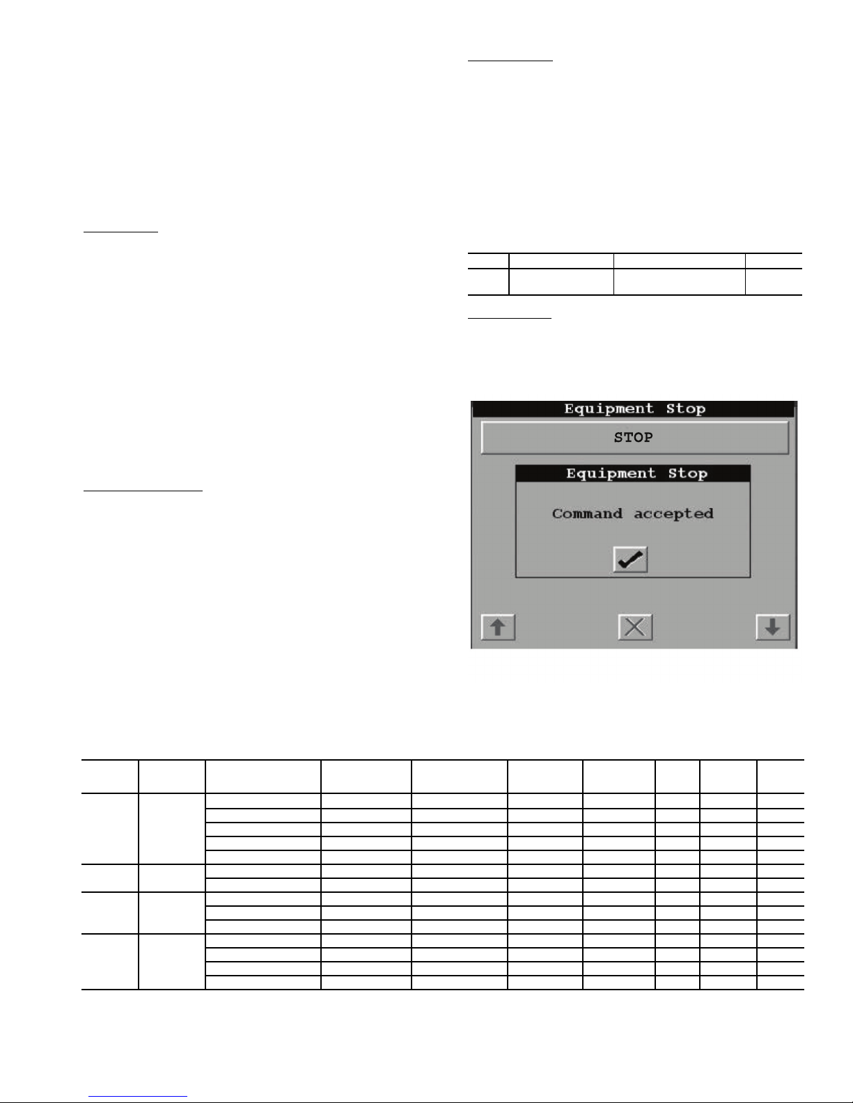
displayed. Select Remote Mode. The unit will be controlled by
Fig. 19 — Equipment Stop Screen
the Enable/Off/Remote Contact switch. Switching the Enable/
Off/Remote Contact switch to the Enable or Remote Contact position (external contacts closed) will force the unit into
an occupied state. In this mode, all CCN network force commands, except the Emergency Stop Command will be ignored.
The Run Status variable will indicate the current status of the
machine (OFF, RUNNING, DELAY, or READY), depending
on the position of the Remote/Off/Enable Switch closure. The
Chiller Occupied? variable will change to YES. The Control
Type variable will change to Remote. The Operating Type
variable will change to Remote.
Master Mode
— To activate Dual Chiller Control, each machine must be individually configured for Dual Chiller Control.
To operate the machines in Dual Chiller Mode, one machine
must be designated as the master unit and one machine as the
slave unit. On the master unit, press the Start/Stop button on the
Touch Pilot display. The Equipment Start screen will be displayed. Select Master Mode. Failure to start the Master unit in
this manner will cause both machines to operate in local mode.
The Master Unit Control can be done locally, remotely or
through CCN commands per the master/slave configuration
(Master Control Type). The control will ignore the position of
Enable/Off/Remote Contact switch if the Master Control
Type is configured for Local Control or CCN Control. The
Run Status variable, Chiller Occupied? variable, and Control Type variable will change based on the Master Control
Type configured above and the Machine On/Off Control de-
fined above. The Operating Type variable will change to
Master.
To Turn Machine Off
— To turn the machine off, press the
Start/Stop button on the Touch Pilot display. See Fig. 19. The
machine will shut down. While the unit is in Local Off, it will
remain shut down and ignore all CCN commands as well as
the position of Enable/Off/Remote Contact switch. The Run
Status variable, indicating the current status of the machine,
will change to OFF. The Chiller Occupied? variable will
change to NO. The Control Type variable will indicate
Local. The Operating Type variable will change to L-OFF
(Local Off).
NAVIGATOR™ DISPLAY MACHINE CONTROL —
Machine On/Off control with the Navigator display is determined by the configuration of the Operating Type Control
(OPER). Options to control the machine locally via a switch,
from a local Time Schedule, or via a Carrier Comfort Net-
®
work
command are offered. See Table 21.
Switch Control
— In the Switch Control operating type, the
Enable/Off/Remote Contact switch controls the machine locally. All models are factory configured with Operating Type
Control (OPER) set to SWITCH CTRL (Switch Control).
With SWITCH CTRL, switching the Enable/Off/Remote
Contact switch to the Enable or Remote Contact position (external contacts closed) will put the chiller in an occupied state.
The Unit Run Status (STAT) will indicate the current status of
the machine and will change from OFF to RUNNING or
DELAY. The unit Occupied Status (OCC) will change from
NO to YES. The Status Unit Control Type (CTRL) will change
from LOCAL OFF when the switch is Off to LOCAL ON
when in the Enable position or in the Remote Contact position
with external contacts closed.
ITEM ITEM EXPANSION PATH VALUE
Operating Control
OPER
Ty p e
Time Schedule
— With Time Schedule Operating Type con-
Operating
Modes
SLCTOPER
SWITCH
CTRL
trol, the machine operates under a local schedule programmed
by the user as long as the Enable/Off/Remote Contact switch is
in the Enable or Remote Contact position (external contacts
closed). To operate under this Operating Type Control (OPER)
must be set to TIME SCHED (Time Schedule).
CONTROL
METHOD
(OPER)
All Local Off
Switch
Control
Time
Schedule
CCN
Control
ACTI VE
OPERATING
TYPE
Local On
Local
Schedule
CCN
REMOTE/OFF/ENABLE
SWITCH
Off — — — — —
Remote Open — — — — — Off
————Enable——Off
—————Yes—Off
— — — — — — Closed Off
Enable — — — Disable — — On
Remote Closed — — Disable — — On
Enable — Occupied — Disable — — On
Remote Closed Occupied — Disable — — On
— — Unoccupied — Disable — — Off
Remote Closed — Enable Disable — — On
Remote Closed — Disable Disable — — Off
Enable — — Enable Disable — — On
Enable — — Disable Disable — — Off
Table 21 — Navigator Start/Stop Control
REMOTE ON/OFF
SWITCH
TIME SCHEDULE 1
CCN CHILLER
START/STOP
(CHIL_S_S)
25
EMERGENCY
STOP
(EMSTOP)
ALARM
REMOTE
LOCKOUT
SWITCH
—
UNIT
STATUS
Off
Page 26
Two Internal Time Schedules are available and must be
field programmed. Time Schedule 1 (SCH1) is used for single
set point On-Off control. Time Schedule 2 (SCH2) is used for
dual set point On-Off and Occupied-Unoccupied set point control. The control will use the operating schedules as defined under the Time Clock mode in the Navigator display module.
ITEM ITEM EXPANSION PATH VALUE
OPER
Operating Control
Ty pe
Operating
Modes
SLCTOPER
TIME
SCHED
The schedules consist of 8 user-configurable occupied time
periods. The control supports time schedules for local control,
remote control, and ice building. These time periods can be
flagged to be in effect or not in effect on each day of the week.
The day begins at 00.00 and ends at 24.00. The machine is in
unoccupied mode unless a scheduled time period is in effect. If
an occupied period is to extend past midnight, the occupied
period must end at 24:00 hours (midnight) and a new occupied
period must be programmed to begin at 00:00 hours.
In the following example, a early morning pulldown time
period is scheduled for Monday morning from 12:00 AM to
3:00 AM. The occupied period starts at 7:00 AM, Monday
through Saturday. The occupied time ends at 6:00 PM on Monday and Tuesday, 9:30 PM on Wednesday, 5:00 PM on Thursday and Friday, and 12:00 PM on Saturday.
NOTE: This schedule was designed to illustrate the programming of the schedule function and is not intended as a recommended schedule for chiller operation.
If the chiller is to be controlled to a single set point, use
Schedule 1 (SCH1). This type of schedule will start and stop
the machine only. During the unoccupied times, the chiller will
be off. If the chiller is to be controlled to 2 set points, occupied
and unoccupied, use Schedule 2 (SCH2). This will cause the
chiller to control to an occupied set point and an unoccupied set
point. The machine will be able to provide cooling at any time.
To configure this option while using the Navigator™ display, see Table 22.
Holiday Schedule
— The unit control allows up to 16 holiday
periods. All holidays are entered with numerical values. First
enter the month (MON.x), then the day (DAY.x), then the
duration (DUR.x) of the holiday period in days. If a holiday in
included in one of the Occupied Time Periods of the schedule,
the machine will follow that operating condition for the
holiday. In the following examples, the holidays July 4 and
December 25-26 are programmed for Holiday 1 and Holiday 2
respectively.
To configure this option for the Navigator display, see
Table 23.
CCN Global Time Schedule
— A CCN global schedule can
be used if desired. The schedule number can be set anywhere
from 65 to 99 for operation under a CCN global schedule. The
30XA chillers can be configured to follow a CCN Global
Time Schedule broadcast by another system element. The
ComfortVIEW™ Network Manager’s Configure and Modify
commands or the Service Tool’s Modify/Names function must
be used to change the number of the Occupancy Equipment
Part Table Name (OCC1P01E) to the Global Schedule Number. The Schedule Number can be set from 65 to 99
(OCC1P65E to OCC1P99E).
Table 22 — Configuring Schedules with
Navigator™ Display
ITEM ITEM EXPANSION PATH VALUE
OCC.1 Occupied Time
UNO.1 Unoccupied Time 03:00
MON.1 Monday Select Yes
TUE.1 Tuesday Select No
WED.1 Wednesday Select No
THU.1 Thursday Select No
FRI.1 Friday Select No
SAT.1 Saturday Select No
SUN.1 Sunday Select No
HOL.1 Holiday Select No
OCC.2 Occupied Time
UNO.2 Unoccupied Time 18:00
MON.2 Monday Select Yes
TUE.2 Tuesday Select Yes
WED.2 Wednesday Select No
THU.2 Thursday Select No
FRI.2 Friday Select No
SAT.2 Saturday Select No
SUN.2 Sunday Select No
HOL.2 Holiday Select No
OCC.3 Occupied Time
UNO.3 Unoccupied Time 21:30
MON.3 Monday Select No
TUE.3 Tuesday Select No
WED.3 Wednesday Select Yes
THU.3 Thursday Select No
FRI.3 Friday Select No
SAT.3 Saturday Select No
SUN.3 Sunday Select No
HOL.3 Holiday Select No
OCC.4 Occupied Time
UNO.4 Unoccupied Time 17:00
MON.4 Monday Select No
TUE.4 Tuesday Select No
WED.4 Wednesday Select No
THU.4 Thursday Select Yes
FRI.4 Friday Select Yes
SAT.4 Saturday Select No
SUN.4 Sunday Select No
HOL.4 Holiday Select No
OCC.5 Occupied Time
UNO.5 Unoccupied Time 12:00
MON.5 Monday Select No
TUE.5 Tuesday Select No
WED.5 Wednesday Select No
THU.5 Thursday Select No
FRI.5 Friday Select No
SAT.5 Saturday Select Yes
SUN.5 Sunday Select No
HOL.5 Holiday Select No
Clock
Clock
Clock
Clock
Clock
ClockSCH2PER.3
Clock
Clock
Clock
Clock
Time
SCH1PER.1
or Time
SCH2PER.1
Time
SCH1PER.2
or Time
SCH2PER.2
Time
SCH1PER.3
or Time
Time
SCH1PER.4
or Time
SCH2PER.4
Time
SCH1PER.5
or Time
SCH2PER.5
00:00
07:00
07:00
07:00
07:00
Table 23 — Configuring Holiday Schedules
for Navigator Display
ITEM ITEM EXPANSION PATH VALUE
MON.1 Holiday Start Month
DAY.1 Holiday Start Day 4
DUR.1 Holiday Duration in Day 1
MON.2 Holiday Start Month
DAY.2 Holiday Start Day 25
DUR.2 Holiday Duration in Day 2
Clock
Clock
Time
HOLIHOL.1
Time
HOLIHOL.2
26
7
12
Page 27
The Occupancy Supervisory Part table name (OCC1P01S)
number must be changed to configure the unit to broadcast a
Global Time Schedule. The Schedule Number can be set from
65 to 99 (OCC1P65S to OCC1P99S). When OCC1PxxS is set
to a value greater than 64, an occupancy flag is broadcast over
the CCN every time it transitions from occupied to unoccupied
or vice-versa. By configuring their appropriate Time Schedule
decisions to the same number, other devices on the network can
follow this same schedule. The Enable/Off/Remote Contact
must be in the Enable position or the Remote Contact position
with the contacts closed for the unit to operate. The Unit Run
Status (STAT) will indicate the current status of the machine
(OFF, RUNNING, STOPPING or DELAY), depending on the
schedule. The unit Occupied status (OCC) will indicate the
current occupied schedule according to the schedule, either NO
or YES. The Status Unit Control Type (CTRL) will be LOCAL
OFF when the switch is Off. The Status Unit Control Type will
be CCN when the Enable/Off/Remote Contact switch input is
On.
CCN Control
— With CCN Operating Type control, the machine operates under CCN control as long as the Enable/Off/
Remote Contact Switch is in the Enable or Remote Contact
position (external contacts closed.) To operate under this
Operating Control, OPER must be set to CCN CONTROL. An
external CCN device, such as Chillervisor, controls the On/Off
state of the machine. When controlled by a Chillervisor, it is
recommended that the Auto Start When SM Lost (AU.SM) be
set to Yes.
Careful evaluation of Chilled Water Plant control should be
reviewed. In the event Local Control is established, be sure that
all pumps, valves, and other devices are capable of operating
properly. In the event of a loss of communication with the network, the machine will start and be controlled locally. The
CCN device forces the variable CHIL_S_S to control the chiller. The Unit Run Status (STAT) will indicate the current status
of the machine (OFF, RUNNING, STOPPING or DELAY),
depending on the CCN command. The unit Occupied status
(OCC) will indicate the current occupied state according to the
CCN command and will be displayed as either NO or YES.
The Status Unit Control Type (CTRL) will be LOCAL OFF
when the Enable/Off/Remote Contact switch is Off. The Status
Unit Control Type will be CCN when the Enable/Off/Remote
Contact switch input is Closed and the CHIL_S_S variable is
Stop or Start.
For Dual Chiller Control applications, the Slave Chiller
must be enabled using the CCN CONTROL option.
ITEM ITEM EXPANSION PATH VALUE
OPER
AU.SM
Operating Control
Ty p e
Auto Start when
SM Lost
Operating
Modes
SLCTOPER
ConfigurationSERV YES
CCN
CONTROL
Fluid Set Point Control Location — The factory
default for the chilled water fluid set point is controlling to the
leaving water temperature. An option to configure the machine
for entering water control is available. The control operation
remains the same except the control point is focused on the
entering water temperature, rather than the leaving water temperature when configured.
To configure this option for the Touch Pilot™ display:
DISPLAY NAME PATH
Entering Fluid
Control
Service\
SERVICE1
LINE
NO.
No = Leaving Water Control
5
Yes = Entering Water Control
VAL UE
To configure this option for the Navigator™ display:
ITEM ITEM EXPANSION PATH VALUE
EWTO Entering Water
Control
Configuration
SERV No = Leaving
Water Control
Yes = Entering
Water Control
Cooling Set Point Selection — Several options for
controlling the Leaving Chilled Water Set Point are offered and
are configured by the Cooling Set Point Select (Setpoint Se-
lect, SP.SE) variable. In addition to the Cooling Set Point Se-
lect, Ice Mode Enable discussed later in this book, and Heat
Cool Select (Heat/Cool Select, HC.SE) variables also have a
role in determining the set point of the machine. All units are
shipped from the factory with the Heat Cool Select set to 0.
All default set points are based on Leaving Water Control
(Entering Fluid Control, EWTO) set to No. Values must be
confirmed for the individual set points. Limits for the set points
are listed in the configurations noted below.
To configure these options for the Touch Pilot display, see
Table 24A. To configure these options for the Navigator display, see Table 24B.
Table 24A — Cooling Set Point Selection
with Touch Pilot Display
DISPLAY NAME PATH
Cooling Setpoint 1 Setpoint 2 Range: 14 to 70 F
Cooling Setpoint 2 Setpoint 3 Range: 14 to 70 F
Cooling Ice Setpoint Setpoint 4 Range: -20 to 32 F
Table 24B — Cooling Set Point Selection
with Navigator Display
ITEM ITEM EXPANSION PATH VALUE
CSP.1 Cooling Setpoint 1 Setpoints
CSP.2 Cooling Setpoint 2 Setpoints
CSP.3 Ice Setpoint Setpoints
In all cases, there are limits on what values are allowed for
each set point. These values depend on the Cooler Fluid Type
and the Brine Freeze Set point, discussed later. See Table 25.
Table 25 — Configuration Set Point Limits
SET POINT LIMITS
Minimum * 38 F (3.3 C) 14 F (–10.0 C)
Maximum 60 F (15.5 C)
*The minimum set point for Medium Temperature Brine applications
is related to the Brine Freeze Point. The set point is limited to be no
less than the Brine Freeze Point +5° F (2.8° C).
The Setpoint Select configuration can be set to five different
control options: Set Point Occupancy, Set Point 1, Set Point 2,
4-20 mA Input, and Dual Switch.
SET POINT OCCUPANCY — Set Point Occupancy is the
default configuration for the Setpoint Select variable. When
Setpoint Select (Setpoint Select, SP.SE) is configured to 0
(Setpoint Occ), the unit’s active set point is based on Cooling
LINE
NO.
COOL
COOL
COOL
COOLER FLUID TYPE
(COOLER FLUID TYPE, FLUD)
1, Water 2, Brine
VALU E
(–10.0 to 21.1 C)
Default: 44 F (6.6 C)
(–10.0 to 21.1 C)
Default: 44 F (6.6 C)
(–28.9 to 0 C)
Default: 44 F (6.6 C)
Range: 14 to 70 F
(–10.0 to 21.1 C)
Default: 44 F (6.6 C)
Range: 14 to 70 F
(–10.0 to 21.1 C)
Default: 44 F (6.6 C)
Range: -20 to 32 F
(–28.9 to 0 C)
Default: 44 F (6.6 C)
27
Page 28

Set Point 1 (Cooling Setpoint 1, CSP.1) during the occupied
period while operating under Time Schedule 1 (SCH1). If the
Time Schedule 2 (SCH2) is in use, the unit’s active set point is
based on Cooling Set Point 1 (Cooling Setpoint 1, CSP.1) dur-
ing the occupied period and Cooling Set Point 2 (Cooling Set-
point 2, CSP.2) during the unoccupied period. See Tables 26
and 27.
To configure this option while using a Touch Pilot display:
DISPLAY NAME PATH
Setpoint select StatusGENUNIT 25 0 (Setpoint Occupied)
LINE
NO.
VAL UE
To change this value, a Control Point Force must be applied.
When configured correctly, Setpoint Control (Setpoint
Control, SP.SE) will indicate Auto.
To configure this option while using a Navigator display:
ITEM ITEM EXPANSION PATH VALUE
SP.SE Setpoint Select Operating Modes
Set Point 1
— When Set Point Select (Setpoint Select, SP.SE)
SLCT Setpoint Occ
is configured to 1 (Setpoint 1), the unit’s active set point is
based on Cooling Set Point 1 (Cooling Setpoint 1, CSP.1).
To configure this option with the Touch Pilot display:
The following equation is used to control the set point. See
Fig. 20.
Fahrenheit Set Point = 10 + 70(mA – 4)/16 (deg F)
Celsius Set Point = –12.2 + 38.9(mA – 4)/16 (deg C)
To configure this option while using a Touch Pilot display:
DISPLAY NAME PATH
Setpoint select StatusGENUNIT 25 3 (4-20 mA Input)
LINE
NO.
VAL UE
To change this value, a Control Point Force must be applied.
When configured correctly, Setpoint Control will indicate 420 mA.
To configure this option while using a Navigator display:
ITEM ITEM EXPANSION PATH VALUE
SP.SE Setpoint Select Operating Modes
Dual Switch
— When Set Point Select (Setpoint Select,
SLCT 4-20 mA Setp
SP.SE) is configured to 4 (Dual Setp Sw), the unit’s active set
point is based on Cooling Set Point 1 (Cooling Setpoint 1,
CSP.1) when the Dual Set Point switch contact is open and
Cooling Set Point 2 (Cooling Setpoint 2, CSP.2) when it is
closed.
To configure this option while using a Touch Pilot display:
DISPLAY NAME PATH
Setpoint select Status
GENUNIT 25 1 (Set Point 1)
LINE
NO.
VAL UE
To change this value, a Control Point Force must be applied.
When configured correctly, Setpoint Control will indicate
Setp 1.
To configure this option with the Navigator™ display:
ITEM ITEM EXPANSION PATH VALUE
SP.SE Setpoint Select Operating Modes
Set Point 2
— When Set Point Select (Setpoint Select, SP.SE)
SLCT Setpoint 1
is configured to 2 (Setpoint 2), the unit’s active set point is
based on Cooling Set Point 2 (Cooling Setpoint 2, CSP.2).
To configure this option with the Touch Pilot™ display:
DISPLAY NAME PATH
Setpoint select Status
GENUNIT 25 2 (Set Point 2)
LINE
NO.
VAL UE
To change this value, a Control Point Force must be applied.
When configured correctly, Setpoint Control (Status
GENUNIT) will indicate Setp 2.
To configure this option with the Navigator display:
ITEM ITEM EXPANSION PATH VALUE
SP.SE Setpoint Select Operating Modes
4 to 20 mA Input
— When Set Point Select (Setpoint Select,
SLCT Setpoint 2
SP.SE) is configured to 3 (4-20 mA Setp), the unit’s active set
point is based on an field supplied, external 4 to 20 mA signal
input to the Energy Management Module (EMM). Care should
be taken when interfacing with other manufacturer’s control
systems, due to power supply differences of full wave bridge
versus half wave rectification. The two different power supplies cannot be mixed. ComfortLink™ controls use half wave
rectification. A signal isolation device should be utilized if a
full wave bridge signal generating device is used.
DISPLAY NAME PATH
Setpoint select Status
GENUNIT 25
LINE
NO.
4 (Dual
Setpoint Switch)
VAL UE
To change this value, a Control Point Force must be applied.
When configured correctly, Setpoint Control will indicate
Setp Sw.
To configure this option while using a Navigator display:
ITEM ITEM EXPANSION PATH VALUE
SP.SE Setpoint Select Operating Modes
SLCT
Dual
Setp Sw
Chilled Water Fluid Type Selection — The chilled
water fluid must be configured. The fluid type must be configured to obtain the proper leaving water set point control range
and freeze protection. The Cooler Fluid Type (Cooler Fluid
Typ e, FLUD) can be set to water or brine.
FRESH WATER — Configure the unit for Cooler Fluid Type
(Cooler Fluid Type, FLUD) to water for units without brine or
glycol installed in the chilled water loop. The factory default
fluid type is fresh water. Use this option for fresh water systems. This will allow for a water temperature set point of 38 to
60 F (3.3 to 15.5 C). With water as the selection, the Freeze
Point is fixed at 34 F (1.1 C).
To configure this option with the Touch Pilot display:
DISPLAY
NAME
Cooler
Fluid Type
Main Menu
PATH
ServiceSERVICE1 1 1 = Water
To configure this option with the Navigator display:
ITEM ITEM EXPANSION PATH VALUE
FLUD Cooler Fluid Type Configuration
LINE
VAL UE
NO.
SERV Water
28
Page 29
Table 26 — Cooling Set Point Selection Touch Pilot™ Parameters
0
10
20
30
40
50
60
70
80
90
02 468 10 12 14 16 18 20
mA Signal
Set Point
Max LWT
Min LWT, Cooler Fluid Type = 1, FLUD=Brine
Min LWT, Cooler Fluid Type = 1, FLUD=Water
Fig. 20 — 4 to 20 mA Set Point Control
a30-4476
SET POINT
CONFIGURATION
(Setpoint Select)
0
(Auto)
1 (Setp 1) — — — — Cooling Setpoint 1
2 (Setp 2) — — — — Cooling Setpoint 2
3 (4-20 mA) — — — — 4 to 20 mA Input
4 (Setp Sw)
Table 27 — Cooling Set Point Selection Navigator™ Parameters
Control Method
(OPER)
LOCAL COOL
CCN COOL
Heat/Cool
Select (HC.SE)
ICE MODE
ENABLE
(ice_cnfg)
NO
DUAL SET
POINT INPUT
(SETP_SW)
— — Occupied Cooling Setpoint 1
— — Unoccupied Cooling Setpoint 2
— Open Unoccupied Cooling Ice Setpoint
YES
— Closed Unoccupied Cooling Setpoint 2
— — Occupied Cooling Setpoint 1
NO
Open — — Cooling Setpoint 1
Closed — — Cooling Setpoint 2
Open — — Cooling Setpoint 1
YES
Closed Open — Cooling Ice Setpoint
Closed Closed — Cooling Setpoint 2
PARAMETER STATUS
Setpoint
Select (SP.SE)
Ice Mode
Enable (ICE.M)
Setpoint Occ — — — Occupied CSP.1
Setpoint Occ — — — Unoccupied CSP.2
Setpoint Occ Enable Open — Unoccupied CSP.3
Setpoint 1 — — — — CSP.1
Setpoint 2 — — — — CSP.2
4-20mA Setp — — — — 4_20mA
— Enable Open Closed — CSP.3
— Enable Closed Closed — CSP.2
— — — Open — CSP.1
Dual Setp Sw — — Closed — CSP.2
— — — — Occupied CSP.1
— — — — Unoccupied CSP.2
ICE DONE INPUT
(ICE_SW)
Ice Done
(ICE.D)
TIME
SCHEDULE 2
Dual Setpoint
Switch (DUAL)
SET POINT
Setpoint
Occupied
(SP.OC)
ACTIVE
ACTIVE
SET POINT
29
Page 30
BRINE OR GLYCOL OPERATION — Configure the unit
for Cooler Fluid Type (Cooler Fluid Type, FLUD) to brine for
brine or glycol chilled water loops. This option will allow for a
set point temperature range of 14 to 60 F (–10.0 to 15.5 C).
Before configuring this selection, confirm that a suitable antifreeze has been added and is at a sufficient concentration to
protect the loop. Additionally, the Brine Freeze Set Point
(Brine Freeze Setpoint, LOSP) must be set for proper freeze
protection operation. Set the Brine Freeze Set Point to the burst
protection provided by the glycol concentration. This value
will be Freeze Point for the fluid.
To configure this option with the Touch Pilot display:
DISPLAY
NAME
Cooler Fluid
Type
Brine Freeze
Setpoint
PAT H
Main Menu
ServiceSERVICE1
Main Menu
ServiceSERVICE1
LINE
NO.
12 = Brine
3
VAL UE
Dependent on
fluid concentration
To configure this option with the Navigator display:
ITEM ITEM EXPANSION PATH VALUE
FLUD Cooler Fluid Type Configuration
Brine Freeze
LOSP
Setpoint
ConfigurationSERV
SERV Brine
Dependent on
fluid concentration
Cooler Pump Control — It is required for flooded
cooler units that cooler pump control be utilized on all chillers
unless the chilled water pump runs continuously or the chilled
water system contains a suitable antifreeze solution. The 30XA
units can be configured for single external pump control as
standard. Control of dual external pumps requires installation
of the external pump control accessory package (Part No.
00EFN900003200A).
Cooler Pumps Sequence (Cooler Pumps Sequence,
PUMP) is the variable that must be confirmed in the field.
Proper configuration of the cooler pump control is required to
provide reliable chiller operation. Pump control can be accomplished for both on-board and external pumps. For external
pump control, control connections to the pump contactor and a
feedback circuit from the contactor must be supplied. The
Cooler Pumps Sequence configuration can be set to 5 different
control settings: No Pump Control, Single Pump Control, Dual
Pump Control, Pump 1 Manual, and Pump 2 Manual.
When the Cooler Pumps Sequence is configured, the cooler
pump output will be energized when the chiller enters an “ON”
mode. The cooler pump output is also energized when certain
alarms are generated. The cooler pump output should be used
as an override to the external pump control if cooler pump control is not utilized. The cooler pump output is energized if a
P.01 Water Exchanger Freeze Protection alarm is generated,
which provides additional freeze protection if the system is not
protected with a suitable antifreeze solution.
A chilled water pump interlock contact PMP-I is connected
across TB5 terminals 1-2, as an alternative to the standard
jumper. This interlock is an optional field-installed device
which would provide extra protection in the event of the flow
switch failing closed. It may be used regardless of whether or
not pump control is enabled. However, this interlock should
NOT be confused with the pump contactor feedback auxiliary
contacts which MUST be wired to MBB channel 18 at connector J5C if the pump control feature is enabled (with or without
the optional on-board hydronic package).
NO PUMP CONTROL — The factory default setting for
Cooler Pumps Sequence (Cooler Pumps Sequence, PUMP)
is 0 (No Pump), for units without the factory-installed hydronic
package.
When Cooler Pumps Sequence is set to 0 (No Pump), closure of both the chilled water flow switch (CWFS) and the
chilled water pump interlock contact (connected across TB-5
terminals 1 and 2) are required for the unit to start mechanical
cooling.
To configure this option with the Touch Pilot™ display:
DISPLAY NAME PATH
Cooler Pumps
Sequence
Main
Menu
ConfigUSER
LINE
NO.
8
VAL UE
0 (No Pump
Control)
To configure this option with the Navigator™ display:
ITEM ITEM EXPANSION PATH VALUE
PUMP
Cooler Pumps
Sequence
Configuration
OPTN No Pump
SINGLE PUMP CONTROL — For units with the single
pump hydronic package, the factory default setting for Cooler
Pumps Sequence (Cooler Pumps Sequence, PUMP) is 1
(1 Pump Only). This control algorithm may be used to control
an external pump, as long as the same controls are applied as
noted below.
When the Cooler Pumps Sequence configuration is set to 1
Pump Only, closure of both the chilled water flow switch
(CWFS) and the chilled water pump interlock contact (connected across TB-5 terminals 1 and 2) are required for the unit
to start mechanical cooling. Additionally, the normally open
auxiliary contacts for Pump 1 contactor must be connected to
the violet and pink wires located in the harness from the MBBJ5C-CH18 connector. The wires in the harness are marked
“PMP1-13” and “PMP1-14”. See the field wiring diagram in
the 30XA Installation Instructions.
Three additional parameters are configurable for pump control with single pump control. Periodic pump start and check
flow if pump is off parameters can customize the pump operation for the application. Another parameter, to stop the pump in
standby mode is not supported.
The control system has the ability to periodically start the
pumps to maintain the bearing lubrication and seal integrity. If
Periodic Pump Start (Pump Sticking Protection, PM.PS) is
set to YES and the unit is off at 2:00 PM, the pump will be
started once each day for 2 seconds. The default for this option
is NO.
Another configuration to check the status of the chilled
water flow switch can be selected. When configured, if Flow
Checked if Pump Off (Flow Checked if C Pump Off, P.LOC)
is set to YES, the control will monitor the chilled water flow
switch status and will alarm if the pump is commanded off and
the chilled water flow switch is closed. This can provide the
user with information of a faulty cooler pump contactor or a
failed chilled water flow switch. This parameter should be set
to NO for series flow machines. The factory default for this
item is YES.
To configure this option with the Touch Pilot display:
DISPLAY NAME PATH
Cooler Pumps
Sequence
Pump Sticking
Protection
Flow Checked
if C Pump Off
Main
Menu
ConfigUSER
Main
Menu
ConfigUSER
Main
Menu
ConfigUSER
LINE
NO.
15
17
1 (Single
8
Pump Control)
Default = No
No = Disabled
Ye s = E na bl ed
Default = Yes
No = Disabled
Ye s = E na bl ed
VAL UE
30
Page 31
To configure this option with the Navigator display:
To configure these options with the Touch Pilot™ display:
ITEM ITEM EXPANSION PATH VALUE
Cooler Pumps
PUMP
PM.PS
P. LO C
Sequence
Periodic Pump
Start
Flow Checked
if Pmp Off
ConfigurationOPTN 1 Pump Only
Configuration
Configuration
OPTN
OPTN
Default = No
No = Disabled
Ye s = E na bl ed
Default = Yes
No = Disabled
Ye s = E na bl ed
DUAL PUMP AND MANUAL CONTROL — For units with
the dual pump hydronic package, the factory default setting for
Cooler Pumps Sequence (Cooler Pumps Sequence, PUMP)
is 2 (2 Pumps Auto). This control algorithm may be used to
control two external pumps, as long as the same controls are
applied as noted below. For dual pump hydronic option units,
three control options exist. The control will start the pumps and
automatically alternate the operation of the pumps to even the
wear of the pumps based on the hours configured under Pump
Auto Rotation Delay (Pump Auto Rotation Delay, ROT.P). If
the difference between the operating hours of the 2 pumps exceeds the Pump Auto Rotation Delay the lead pump will
change. If a flow failure is detected, the other pump will attempt to start.
Two manual control options also exist. When the Cooler
Pumps Sequence (Cooler Pumps Sequence, PUMP) is set to
3 (PMP 1 Manual), Cooler Pump 1 will always operate. When
the Cooler Pumps Sequence (Cooler Pumps Sequence,
PUMP) is set to 4 (PMP 2 Manual), Cooler Pump 2 will always operate.
If the Cooler Pumps Sequence configuration is set to 2
(2 Pumps Auto), 3 (PMP 1 Manual), or 4 (PMP 2 Manual),
closure of both the chilled water flow switch (CWFS) and the
chilled water pump interlock contact (connected across TB-5
terminals 1 and 2) are required for the unit to start mechanical
cooling. Additionally, the normally open auxiliary contacts for
Pump 1 and Pump 2 contactors (wired in parallel) must be connected to the violet and pink wires located in the harness from
the MBB-J5C-CH18 connector. The wires in the harness are
marked “PMP1-13” and “PMP1-14”. See the field wiring diagram in the 30XA Installation Instructions.
Three additional parameters are configurable for pump control with single pump control. The Periodic Pump Start (Pump
Sticking Protection, PM.PS) and Flow Checked if Pump Off
(Flow Checked if C Pump Off, P.LOC) parameters can cus-
tomize the pump operation for the application. Another parameter, that is used to stop the pump in standby mode, is not
supported.
The control system has the ability to periodically start the
pumps to maintain the bearing lubrication and seal integrity. If
Periodic Pump Start (Pump Sticking Protection, PM.PS) is
set to YES and if the unit is off at 2:00 PM, a pump will be
started once each day for 2 seconds. If the unit has 2 pumps,
Pump 1 will be started on even days (such as day 2, 4, or 6 of
the month); Pump 2 will be started on odd days (such as day 1,
3 or 5 of the month). The default for this option is NO.
A configuration to check the status of the chilled water flow
switch can be selected. When Flow Checked if Pump Off
(Flow Checked if C Pump Off, P.LOC) is configured to YES,
the control will monitor the chilled water flow switch status
and will alarm if the pump is commanded off and the chilled
water flow switch is closed. This can provide the user with
information of a faulty cooler pump contactor or a failed
chilled water flow switch. This parameter should be set to NO
for series flow machines. The factory default for this item is
YES.
DISPLAY NAME PATH
Cooler Pumps
Sequence
Pump Auto
Rotation Delay
Pump Sticking
Protection
Flow Checked
if C Pump Off
Main Menu
ConfigUSER
Main Menu
ConfigUSER
Main Menu
ConfigUSER
Main Menu
ConfigUSER
LINE
NO.
8
14 Default = 48 hours
15
17
VAL UE
2 (2 Pumps Automatic)
3 (Pump 1 Manual)
4 (Pump 2 Manual)
Default = No
No = Disabled
Yes = Enabled
Default = Yes
No = Disabled
Yes = Enabled
To configure these options with the Navigator™ display:
ITEM ITEM EXPANSION PATH VALUE
PUMP
ROT.P
PM.PS
P. LO C
Cooler Pumps
Sequence
Pump Rotation
Delay
Periodic Pump
Start
Flow Checked
if Pmp Off
Configuration
ConfigurationOPTN
Configuration
Configuration
OPTN
OPTN
OPTN
2 Pumps Auto
PMP1 Manual
PMP2 Manual
Default =
48 hours
Default = No
No = Disabled
Yes = Enabled
Default = Yes
No = Disabled
Yes = Enabled
Machine Start Delay — An option to delay the start of
the machine is also available. This parameter is useful in keeping multiple machines from starting at the same time in case of
a power failure. The parameter has a factory default of
1 minute. This parameter also has a role in the timing for a
chilled water flow switch alarm.
To configure this option with the Touch Pilot display:
DISPLAY NAME PATH
Unit Off to
On Delay
Main Menu
ConfigUSER
LINE
NO.
6 Default = 1 Minute
VAL UE
To configure this option with the Navigator display:
ITEM ITEM EXPANSION PATH VALUE
DELY Minutes Off Time Configuration
OPTN
Default =
1 Minute
Circuit/Compressor Staging and Loading —
The AquaForce® 30XA chillers employ one compressor per
circuit. As a result, circuit and compressor staging are the
same. The control has several control option parameters to load
the compressors. The circuit/compressor start can be configured as well as the loading of each circuit/compressor.
CIRCUIT/COMPRESSOR STAGING — The control can be
configured to decide which circuit/compressor starts first, by
configuring Lead/Lag Circuit Select (Staged Loading
Sequence, LLCS). Four options for this variable are allowed:
Automatic Lead-Lag, Circuit A Leads, Circuit B Leads, or
Circuit C Leads (30XA400-500 only). The factory default is
Automatic Lead-Lag.
The automatic lead-lag function determines which circuit/
compressor starts. When enabled, the control will determine
which circuit/compressor starts to even the wear of the compressor. The compressor wear factor (combination of starts and
run hours) is used to determine which compressor starts.
Compressor Wear Factor = (Compressor Starts) + 0.1 (Compressor Run Hours)
The circuit/compressor with the lowest compressor wear
factor is the circuit that starts first.
If starting a particular circuit/compressor first is desired, that
can also be configured with the same variable.
31
Page 32
To configure this option with the Touch Pilot display:
To configure this option with the Navigator display:
DISPLAY NAME PATH
Circuit Loading
Sequence
Main Menu
ConfigUSER
LINE
NO.
1
VAL UE
0 (Automatic Lead-lag)
1 (Circuit A Leads)
2 (Circuit B Leads)
3 (Circuit C Leads)
Default = 0
(Automatic Lead-lag)
To configure this option with the Navigator display:
ITEM ITEM EXPANSION PATH VALUE
Range: Automatic,
LLCS
Lead/Lag
Circuit Select
Configuration
OPTN
Cir A Leads,
Cir B Leads,
Cir C Leads
Default – Automatic
CIRCUIT/COMPRESSOR LOADING — The control can
be configured to stage the circuit/compressors. The Loading
Sequence Select (Circuit Loading Sequence, LOAD) setting
determines how the control will perform loading. The configuration can be set to Equal or Staged.
Equal Loading
— With Equal loading, the circuit which starts
first will maintain the minimum stage of capacity with the slide
valve fully unloaded. When additional capacity is required, the
next circuit with the lowest compressor wear factor is started
with its slide valve at minimum position. As additional capacity is required, the slide valve for a circuit will be adjusted in
approximately 5% increments to match capacity requirements.
The control will alternate between circuits to maintain the same
percentage of capacity on each circuit. See Fig. 21.
Staged Loading
— If staged loading is selected, the circuit
which starts first will gradually load its slide valve to match
capacity requirements until the circuit is fully loaded. Once the
circuit is fully loaded and additional capacity is required, the
control will start an additional circuit fully unloaded. The control will gradually unload the circuit which was fully loaded to
match capacity requirements. See Fig. 21.
To configure this option with the Touch Pilot™ display:
DISPLAY NAME PATH
Staged Loading
Sequence
Main
ConfigUSER
Menu
LINE
NO.
4
VAL UE
Default = No
No (Equal)
Yes (Staged)
To configure this option with the Navigator™ display:
ITEM ITEM EXPANSION PATH VALUE
Loading Sequence
LOAD
Select
Configuration
OPTN
Default = Equal
Equal
Staged
Minimum Load Control — Minimum Load Control
can be a factory-installed option or a field-installed accessory.
If installed, and its operation is desired, the Minimum Load
Control must be enabled. Once enabled, the valve will be operational only during the first stage of cooling.
To configure this option with the Touch Pilot display:
DISPLAY NAME PATH
Hot Gas
Bypass Select
Main
Menu
Service
FACTO RY
LINE
NO.
14
VALU E
Default = No
No (No Minimum
Load Control)
Yes (Minimum Load
Control Installed)
ITEM
HGBP
ITEM
EXPANSION
Hot Gas
Bypass Select
PATH VALUE
Configuration
UNIT
No = No Minimum
Load Control
Yes = Minimum Load
Control Installed
Dual Chiller Control — The dual chiller routine is
available for the control of two units installed in series or parallel supplying chilled fluid on a common loop. One chiller must
be configured as the master chiller, the other as the slave chiller. An additional leaving fluid temperature thermistor (Dual
Chiller LWT) must be installed in the common chilled water
piping as described in the Installation Instructions for both the
master and slave chillers. See the Field Wiring section in the
30XA Installation Instructions for Dual Chiller LWT sensor
control wiring.
The control algorithm relies on several parameters that must
be field configured for operation. Both chillers must be on the
same Carrier Comfort Network
On both chillers, Master/Slave Select (Master/Slave Select,
MSSL) must be enabled. The water piping arrangement, Chillers in Series (Chiller in Series, SERI), must be configured.
The master chiller must be programmed with the Slave Chiller
Address (Slave Address, SLVA). Additional optional pro-
gramming parameters may be configured to meet application
requirements.
Lead/Lag Balance Select (Lead Lag Select, LLBL) determines which chiller is the lead machine. The options are Always Lead, Lag if Fail, and Runtime Select. Under Runtime
Select control, the lead chiller will change based on the time increment selected in the Lead/Lag Balance Delta configuration
(Lead/Lag Balance Data, LLBD). If the run hour difference
between the master and the slave remains less than the Lead/
Lag Balance Delta, the chiller designated as the lead will
remain the lead chiller. The Lead/Lag changeover between the
master and the slave chiller due to hour balance will occur during chiller operating odd days, such as day 1, day 3, and day 5
of the month, at 12:00 a.m. If a lead chiller is not designated,
the master chiller will always be designated the lead chiller.
The dual chiller control algorithm has the ability to delay
the start of the lag chiller in two ways. The Lead Pulldown
Time parameter (Lead Pulldown Type, LPUL) is a one-time
time delay initiated after starting the lead chiller, before checking whether to start an additional chiller. This time delay gives
the lead chiller a chance to remove the heat that the chilled
water loop picked up while being inactive during an unoccupied period. The second time delay, Lead/Lag Delay (Lag
Start Timer, LLDY) is a time delay imposed between the last
stage of the lead chiller and the start of the lag chiller. This prevents enabling the lag chiller until the lead/lag delay timer has
expired.
A quicker start of the lag chiller can be accomplished by
configuring the Start if Error Higher parameter (Start if Error
Higher, LL.ER). If the difference between the common leav-
ing water temperature and the set point is greater than the configured value, then the lag chiller will start.
A minimum on time for the lag chiller can be programmed
with the Lag Minimum Running Time configuration (Lag
Minimum Running Time, LAG.M). This parameter causes
the control to run the lag chiller for the programmed minimum
on time. The Lag Unit Pump Select (Lag Unit Pump Control,
LAGP) can be configured such that the pump can be on or off
while the chiller is off. This parameter is only active in Parallel
Chiller Operation.
®
bus with different addresses.
32
Page 33
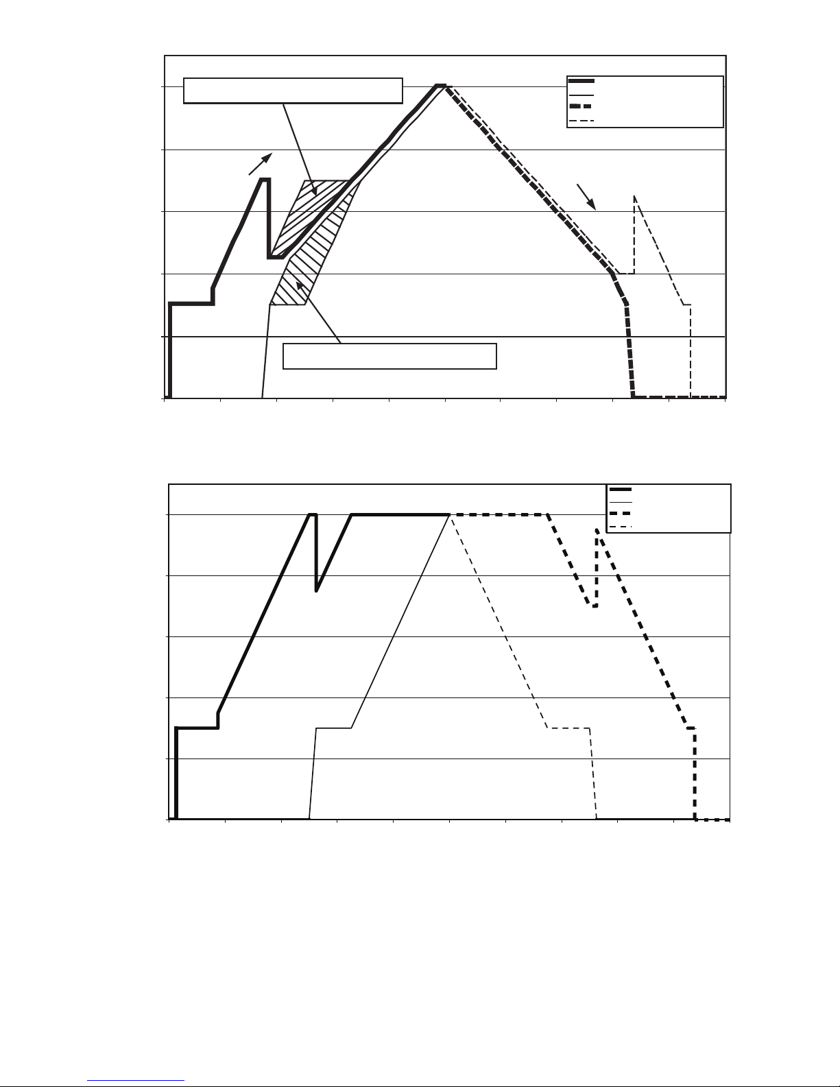
Compressor Loading Unloading (Staged circuit loading)
0
20
40
60
80
100
Load (%)
Compressor Capacity (%)
Lead Compressor Loading
Lag Compressor Loading
Lead Compressor Unloading
Lag Compressor Unloading
100
0
0
0
20
40
60
80
100
g
g
Lead compressor can fall anywhere in this area
LOADING
UNLOADING
Compressor Capacity (%)
Equal Circuit Loading
Staged Circuit Loading
Fig. 21 — Compressor Loading and Unloading
a30-4466
a30-4477
when load between 40%~65%
Lag compressor can fall anywhere in this area
when load between 40%~65%
Lead Compressor Loading
Lag Compressor Loading
Lead Compressor Unloading
Compressor Unloadin
La
0 0
100
Load (%)
For units with a Touch Pilot display, two additional steps
must be completed to start the machine. On the master chiller,
the Master Control Type must be configured for the start control defined in the Machine Control configuration. To start the
machines, the master chiller must be started with the Start/Stop
button and Master Mode selected. The slave chiller must be
started with the CCN Mode selected.
Each application, Parallel and Series, are described separately below.
DUAL CHILLER CONTROL FOR PARALLEL APPLICATIONS — To configure the master chiller for parallel
applications using the Touch Pilot display, see Table 28. To
configure the master chiller for parallel applications using the
Navigator display, see Table 29.
To configure the slave chiller for parallel applications using
the Touch Pilot display, see Table 30. To configure the slave
chiller for parallel applications using the Navigator display, see
Table 31. A power cycle is required for the values to take
effect.
33
Page 34
Table 28 — Dual Master Chiller Control Parameters for Parallel Applications with Touch Pilot™ Display
DISPLAY NAME PATH LINE NO. VALUE
Master/Slave Select Main Menu
Master Control Type Main Menu
Slave Address Main Menu
Lead Lag Select Main Menu
Lead/Lag Balance Delta Main Menu
Lag Start Timer Main Menu
Lead Pulldown Time Main Menu
Start If Error Higher Main Menu
Lag Minimum Running Time Main Menu
Lag Unit Pump Control Main Menu
Chiller In Series Main MenuConfigMST_SLV 22
NOTE: If pump control is configured to OFF, then LAG UNIT PUMP
SELECT = 1. If pump control is set to any other value, then LAG
UNIT PUMP SELECT = 0. This configuration must be set consistently for both master and slave chillers.
ConfigMST_SLV 3
ConfigMST_SLV 7
ConfigMST_SLV 11
ConfigMST_SLV 12
ConfigMST_SLV 16
ConfigMST_SLV 17
ConfigMST_SLV 18
ConfigMST_SLV 19
ConfigMST_SLV 20
ConfigMST_SLV 21
1 (Master)
Default: 0 (Disable)
1=Local Control
2=Remote Control
3=CCN Control
Default: 1
Configure for proper control type.
Must be set to the Slave Chiller’s address.
The master and slave chiller must have
different addresses and be on the same
Bus Number
Default: 2
0 (Master Always Leads)
1 (Lag Once Failed Only)
2 (Lead/Lag Runtime Select)
Default: 0 (Master Always Leads)
Range: 40 to 400 hours
Default: 168 hours
Range: 2 to 30 minutes
Default: 10 minutes
Range: 0 to 60 minutes
Default: 0 minutes
Range: 3.0 to 18 F (1.7 to 10.0 C)
Default: 4.0 F (2.2 C)
Range: 0 to 150 minutes
Default: 0 minutes
0 (Stop If Unit Stops)
1 (Run If Unit Stops)
Default: 0 (Stop If Unit Stops)
Default: No
Value: No
Table 29 — Dual Master Chiller Control Parameters for Parallel Applications with Navigator™ Display
ITEM ITEM EXPANSION PATH VALUE
MSSL Master/Slave Select ConfigurationRSET
SLVA Slave Address ConfigurationRSET
LLBL Master Lead Lag Select Configuration
LLBD Lead/Lag Balance Delta Configuration
LLDY Lag Start Delay Configuration
LL.ER Start If Error Higher Configuration
LAG.M Lag Unit Pump Select Configuration
LPUL Lead Pulldown Time Configuration
SERI Chillers in Series Configuration
OPER Operating Control Type Operating Modes
NOTE: If pump control is configured to OFF, then LAG UNIT PUMP
SELECT = 1. If pump control is set to any other value, then LAG
UNIT PUMP SELECT = 0. This configuration must be set consistently for both master and slave chillers.
RSET
RSET
RSET
RSET
RSET
RSET
RSET
SLCT Set to desired control
Master
Default: Disable
Must be set to the Slave Chiller’s address.
The master and slave chiller must have
different addresses and be on the same
Bus Number
Default: 2
Range: Always Lead, Lag if Fail, Runtime Sel
Default: Always Lead
Range: 40 to 400 hours
Default: 168 hours
Range: 2 to 30 minutes
Default: 10 minutes
Range: 3.0 to 18 F (1.7 to 10.0 C)
Default: 4.0 F (2.2 C)
Range: Off If U Stp, On If U Stop
Default: Off If U Stp
Range: 0 to 60 minutes
Default: 0 minutes
No
Default: No
34
Page 35
Table 30 — Dual Slave Chiller Control Parameters for Parallel Applications with Touch Pilot™ Display
DISPLAY NAME PATH LINE NO. VALUE
Master/Slave Select Main Menu
Master Control Type Main Menu
Slave Address Main Menu
Lead Lag Select Main Menu
Lead/Lag Balance Delta Main Menu
Lag Start Timer Main Menu
Lead Pulldown Time Main Menu
Start If Error Higher Main Menu
Lag Minimum Running Time Main Menu
Lag Unit Pump Control Main Menu
Chiller In Series Main MenuConfigMST_SLV 22
NOTE: If pump control is configured to OFF, then LAG UNIT PUMP
SELECT = 1. If pump control is set to any other value, then LAG
UNIT PUMP SELECT = 0. This configuration must be set consistently for both master and slave chillers.
ConfigMST_SLV 3
ConfigMST_SLV 7
ConfigMST_SLV 11
ConfigMST_SLV 12
ConfigMST_SLV 16
ConfigMST_SLV 17
ConfigMST_SLV 18
ConfigMST_SLV 19
ConfigMST_SLV 20
ConfigMST_SLV 21
2 (Slave)
Default: 0 (Disable)
1 (Local Control)
2 (Remote Control)
3 (CCN Control)
Default: 1
Configure for proper control type.
Must be set to the Slave Chiller’s address.
The master and slave chiller must have
different addresses and be on the same
Bus Number
Default: 2
0 (Master Always Leads)
1 (Lag Once Failed Only)
2 (Lead/Lag Runtime Select)
Default: 0 (Master Always Leads)
Range: 40 to 400 hours
Default: 168 hours
Range: 2 to 30 minutes
Default: 10 minutes
Range: 0 to 60 minutes
Default: 0 minutes
Range: 3.0 to 18 F (1.7 to 10.0 C)
Default: 4.0 F (2.2 C)
Range: 0 to 150 minutes
Default: 0 minutes
0 (Stop If Unit Stops)
1 (Run If Unit Stops)
Default: 0 (Stop If Unit Stops)
No
Default: No
Table 31 — Dual Slave Chiller Control Parameters for Parallel Applications with Navigator™ Display
ITEM ITEM EXPANSION PATH VALUE
MSSL Master/Slave Select ConfigurationRSET
SLVA Slave Address Configuration
LLBL Master Lead Lag Select Configuration
LLBD Lead/Lag Balance Delta Configuration
LLDY Lag Start Delay Configuration
LL.ER Start If Error Higher Configuration
LAG.M Lag Unit Pump Select Configuration
LPUL Lead Pulldown Time Configuration
SERI Chillers in Series Configuration
OPER Operating Control Type Operating ModesSLCT CCN Control
NOTE: If pump control is configured to OFF, then LAG UNIT PUMP
SELECT = 1. If pump control is set to any other value, then LAG
UNIT PUMP SELECT = 0. This configuration must be set consistently for both master and slave chillers.
RSET
RSET
RSET
RSET
RSET
RSET
RSET
RSET
Slave
Default: Disable
Must be set to the Slave Chiller’s address.
The master and slave chiller must have
different addresses and be on the same
Bus Number
Default: 2
Range: Always Lead, Lag if Fail, Runtime Sel
Default: Always Lead
Range: 40 to 400 hours
Default: 168 hours
Range: 2 to 30 minutes
Default: 10 minutes
Range: 3.0 to 18 F (1.7 to 10.0 C)
Default: 4.0 F (2.2 C)
Range: Off If U Stp, On If U Stop
Default: Off If U Stp
Range: 0 to 60 minutes
Default: 0 minutes
No,
Default: No
35
Page 36
DUAL CHILLER PUMP CONTROL FOR PARALLEL
CHILLER APPLICATIONS — It is recommended that a
dedicated pump be used for each unit. The chiller must start
and stop its own water pump located on its own piping. If
pumps are not dedicated for each chiller, chiller isolation
valves are required and each chiller must open and close its
own isolation valve.
DUAL CHILLER CONTROL FOR SERIES APPLICATIONS — To configure the master chiller for series applications using the Touch Pilot™ display, see Table 32. To
configure the master chiller for series applications using the
Navigator™ display, see Table 33.
To configure the slave chiller for series applications using
the Touch Pilot™ display, see Table 34. To configure the slave
chiller for series applications using the Navigator™ display,
see Table 35. A power cycle is required for the values to take
effect.
Table 32 — Dual Master Chiller Control Parameters for Series Applications with Touch Pilot™ Display
DISPLAY NAME PATH LINE NO. VALUE
Master/Slave Select Main Menu
Master Control Type Main Menu
Slave Address Main Menu
Lead Lag Select Main Menu
Lead/Lag Balance Delta Main Menu
Lag Start Timer Main Menu
Lead Pulldown Time Main Menu
Start If Error Higher Main Menu
Lag Minimum Running Time Main Menu
Lag Unit Pump Control Main Menu
Chiller In Series Main MenuConfigMST_SLV 22
NOTE: If pump control is configured to OFF, then LAG UNIT PUMP
SELECT = 1. If pump control is set to any other value, then LAG
ConfigMST_SLV 3
ConfigMST_SLV 7
ConfigMST_SLV 11
ConfigMST_SLV 12
ConfigMST_SLV 16
ConfigMST_SLV 17
ConfigMST_SLV 18
ConfigMST_SLV 19
ConfigMST_SLV 20
ConfigMST_SLV 21
UNIT PUMP SELECT = 0. This configuration must be set consistently for both master and slave chillers.
1 (Master)
Default: 0 (Disable)
1 (Local Control)
2 (Remote Control)
3 (CCN Control)
Default: 1 (Local Control)
Value: Configure for proper control type.
Must be set to the Slave Chiller’s address.
The master and slave chiller must have
different addresses and be on the same
Bus Number
Default: 2
0 (Master Always Leads)
1 (Lag Once Failed Only)
2 (Lead/Lag Runtime Select)
Default: 0 (Master Always Leads)
Range: 40 to 400 hours
Default: 168 hours
Range: 2 to 30 minutes
Default: 10 minutes
Range: 0 to 60 minutes
Default: 0 minutes
Range: 3.0 to 18 F (1.7 to 10.0 C)
Default: 4.0 F (2.2 C)
Range: 0 to 150 minutes
Default: 0 minutes
0 (Stop If Unit Stops)
1 (Run If Unit Stops)
Default: 0 (Stop If Unit Stops)
Ye s
Default: No
Table 33 — Dual Master Chiller Control Parameters for Series Applications with Navigator™ Display
ITEM ITEM EXPANSION PATH VALUE
MSSL Master/Slave Select ConfigurationRSET
SLVA Slave Address Configuration
LLBL Master Lead Lag Select Configuration
LLBD Lead/Lag Balance Delta Configuration
LLDY Lag Start Delay Configuration
LL.ER Start If Error Higher Configuration
LAG.M Lag Unit Pump Select Configuration
LPUL Lead Pulldown Time Configuration
SERI Chillers in Series Configuration
OPER Operating Control Type Operating ModesSLCT Set to desired value
NOTE: If pump control is configured to OFF, then LAG UNIT PUMP
SELECT = 1. If pump control is set to any other value, then LAG
UNIT PUMP SELECT = 0. This configuration must be set consistently for both master and slave chillers.
RSET
RSET
RSET
RSET
RSET
RSET
RSET
RSET
36
Master
Default: Disable
Must be set to the Slave Chiller’s address.
The master and slave chiller must have
different addresses and be on the same
Bus Number
Default: 2
Range: Always Lead, Lag if Fail, Runtime Sel
Default: Always Lead
Range: 40 to 400 hours
Default: 168 hours
Range: 2 to 30 minutes
Default: 10 minutes
Range: 3.0 to 18 F (1.7 to 10.0 C)
Default: 4.0 F (2.2 C)
Range: Off If U Stp, On If U Stop
Default: Off If U Stp
Range: 0 to 60 minutes
Default: 0 minutes
YES
Default: NO
Page 37
Table 34 — Dual Slave Chiller Control Parameters for Series Applications with Touch Pilot Display
DISPLAY NAME PATH LINE NO. VALUE
Master/Slave Select Main MenuConfigMST_SLV 3
Master Control Type Main Menu
Slave Address Main Menu
Lead Lag Select Main Menu
Lead/Lag Balance Delta Main Menu
Lag Start Timer Main Menu
Lead Pulldown Time Main Menu
Start If Error Higher Main Menu
Lag Minimum Running Time Main Menu
Lag Unit Pump Control Main Menu
Chiller In Series Main MenuConfigMST_SLV 22
NOTE: If pump control is configured to OFF, then LAG UNIT PUMP
SELECT = 1. If pump control is set to any other value, then LAG
ConfigMST_SLV 7
ConfigMST_SLV 11
ConfigMST_SLV 12
ConfigMST_SLV 16
ConfigMST_SLV 17
ConfigMST_SLV 18
ConfigMST_SLV 19
ConfigMST_SLV 20
ConfigMST_SLV 21
UNIT PUMP SELECT = 0. This configuration must be set consistently for both master and slave chillers.
2 (Slave)
Default: 0 (Disable)
1 (Local Control)
2 (Remote Control)
3 (CCN Control)
Default: 1 (Local Control)
Value: Configure for proper control type.
Must be set to the Slave Chiller’s address.
The master and slave chiller must have
different addresses and be on the same
Bus Number
Default: 2
0 (Master Always Leads)
1 (Lag Once Failed Only)
2 (Lead/Lag Runtime Select)
Default: 0 (Master Always Leads)
Range: 40 to 400 hours
Default: 168 hours
Range: 2 to 30 minutes
Default: 10 minutes
Range: 0 to 60 minutes
Default: 0 minutes
Range: 3.0 to 18 F (1.7 to 10.0 C)
Default: 4.0 F (2.2 C)
Range: 0 to 150 minutes
Default: 0 minutes
0 (Stop If Unit Stops)
1 (Run If Unit Stops)
Default: 0 (Stop If Unit Stops)
Ye s
Default: No
Table 35 — Dual Slave Chiller Control Parameters for Series Applications with Navigator Display
ITEM ITEM EXPANSION PATH VALUE
MSSL Master/Slave Select ConfigurationRSET
SLVA Slave Address ConfigurationRSET
LLBL Master Lead Lag Select Configuration
LLBD Lead/Lag Balance Delta Configuration
LLDY Lag Start Delay Configuration
LL.ER Start If Error Higher Configuration
LAG.M Lag Unit Pump Select Configuration
LPUL Lead Pulldown Time Configuration
SERI Chillers in Series Configuration
OPER Operating Control Type Operating ModesSLCT CCN Control
NOTE: If pump control is configured to OFF, then LAG UNIT PUMP
SELECT = 1. If pump control is set to any other value, then LAG
UNIT PUMP SELECT = 0. This configuration must be set consistently for both master and slave chillers.
RSET
RSET
RSET
RSET
RSET
RSET
RSET
DUAL CHILLER PUMP CONTROL FOR SERIES
CHILLER APPLICATIONS — Pump control for series chiller applications is controlled by the master chiller only. The
control of the slave chiller is directed through commands emitted by the master chiller. The slave chiller has no action in
master/slave operations. The slave chiller only verifies that
CCN communication with the master chiller is present. See the
Dual Chiller Sequence of Operation section on page 68.
Slave
Default: Disable
Must be set to the Slave Chiller’s address.
The master and slave chiller must have
different addresses and be on the same
Bus Number
Default: 2
Range: Always Lead, Lag if Fail,
Runtime Sel
Default: Always Lead
Range: 40 to 400 hours
Default: 168 hours
Range: 2 to 30 minutes
Default: 10 minutes
Range: 3.0 to 18 F (1.7 to 10.0 C)
Default: 4.0 F (2.2 C)
Range: Off If U Stp, On If U Stop
Default: Off If U Stp
Range: 0 to 60 minutes
Default: 0 minutes
YES
Default: NO
Night Time/Low Noise Operation — The Com-
fortLink™ controls have the ability to lower the sound level of
the machine by reducing the number of fans that are running,
provided that the conditions are acceptable. Reducing the number of running fans also limits the capacity. Three parameters
must be configured for this operation. A start and end time for
the mode of operation is required and an optional capacity limit
set point must also be configured.
37
Page 38
If the Start and End Time remain at the factory default
(0:00), then the unit is not programmed for Night Time/Low
Noise Operation.
To configure this option with the Touch Pilot™ display:
DISPLAY NAME PATH
Start Hour Main Menu
End Hour Main Menu
Capacity Limit Main Menu
ConfigUser 39 Default: 00:00
ConfigUser 40 Default: 00:00
ConfigUser 41 Default: 100%
LINE
NO.
VAL UE
To configure this option with the Navigator™ display:
ITEM ITEM EXPANSION PATH VALUE
Night Low Noise
LS.ST
Start
Night Low Noise
LS.ND
End
Low Noise Capacity
LS.LT
Lim
Configuration
Configuration
Configuration
OPTN Default: 00:00
OPTN Default: 00:00
OPTN Default: 100%
Ramp Loading — Ramp Loading limits the rate of
change of the leaving fluid temperature. If the unit is in a Cooling mode and configured for Ramp Loading Select (Ramp
Loading Select, RL.S), the control makes two comparisons
before deciding to increase capacity. First, the control calculates the temperature difference between the control point and
leaving fluid temperature. If the difference is greater than 4° F
(2.2° C) and the rate of change (°F or °C per minute) is more
than the configured Cool Ramp Loading rate (Cooling Ramp
Loading, CRMP), then the control does not allow any increase
of capacity.
To configure this option with the Touch Pilot display:
DISPLAY NAME PATH
Ramp Loading
Select
Cooling Ramp
Loading
Main Menu
ConfigUSER
Main Menu
Setpoint
LINE
NO.
5Yes
14
VALU E
Range: 0.2 to 2.0 °F
(0.1 to 1.1 °C)
Default: 1.0 °F (0.5 °C)
To configure this option with the Navigator display:
ITEM
RL.S
CRMP
ITEM
EXPANSION
Ramp Load
Select
Cool Ramp
Loading
Configuration
Setpoints
PAT H VA LU E
OPTN Yes
COOL
Range: 0.2 to 2.0 °F
(0.1 to 1.1 °C)
Default: 1.0 °F (0.5 °C)
Temperature Reset — Temperature reset is a value
added to the basic leaving fluid temperature set point and the
resulting sum of these values is the new control point. When a
non-zero temperature reset is applied, the chiller controls to the
new control point, not the set point. The type of temperature reset is configured with the Cooling Reset Type (Cooling Reset
Select, CRST) variable. Four types of temperature reset are
available: Return Water Reset, Outside Air Temperature Reset,
Space Temperature Reset, and 4-20 mA Temperature Reset.
Under normal operation, the chiller will maintain a constant
entering or leaving fluid temperature, based on the configuration, approximately equal to the chilled fluid set point. As the
cooler load varies, the cooler fluid temperature difference will
change in proportion to the load. For example, if the chiller was
selected for a Entering to Leaving Water Temperature difference of 10 F (5.5 C) at full load, at 50% load the temperature
difference would be 5 F (2.2 C). See Fig. 22. Because the
change in temperature through the cooler is a measure of the
building load, the temperature difference reset is the average
building load. Usually the chiller size and fluid temperature set
point are selected based on a full load condition. At part load,
the fluid temperature set point may be lower than required. If
the fluid temperature were allowed to increase at part load, the
efficiency of the machine would increase. The chiller can also
be set for return water temperature control. See Fig. 23.
Other indirect means of estimating building load and controlling temperature reset are also available and are discussed
below.
To verify that reset is functioning correctly, subtract the Setpoint Select (Current Setpoint, SETP) from the Control Point
(Control Point, CTPT) to determine the degrees reset.
RETURN WATER RESET — The control system is capable
of performing fluid temperature reset based on cooler fluid
temperature difference. Because the change in temperature
through the cooler is a measure of the building load, the temperature difference reset is, in effect, an average building load
reset method.
Return Water Temperature Reset allows for the chilled
water temperature set point to be reset upward as a function of
the fluid temperature difference (building load).
NOTE: Return Water Temperature Reset should not be used
with variable cooler flow rate systems.
To use Return Water Temperature Reset, four variables
must be configured. Cooling Reset Type (Cooling Reset
Select, CRST) must be enabled. The variable Delta T No Reset
Tem p ( Delta T No Reset Value, CRT1) should be set to the
cooler temperature difference (T) where no chilled water temperature reset should occur. The variable Delta T Full Reset
Tem p ( Delta T Full Reset Value, CRT2) should be set to the
cooler temperature difference where the maximum chilled
water temperature reset should occur. The variable Degrees
Cool Reset (Cooling Reset Deg. Value, DGRC) should be set
to the maximum amount of reset desired.
To configure this option with the Touch Pilot display:
DISPLAY
NAME
Cooling Reset
Select
Delta T No
Reset Temp
Delta T Full
Reset Temp
Cooling Reset
Deg. Value
PATH
Main
Menu
ConfigUSER
Main
MenuSetpointSETPOINT
Main
Menu
SetpointSETPOINT
Main
Menu
SetpointSETPOINT
LINE
NO.
19
7
8
13
VALU E
Default =0
(No Reset)
2 (Delta T)
Default =
0 F (0 C)
Default =
0 F (0 C)
Default =
0 F (0 C)
38
Page 39
40
42
44
46
48
50
52
54
56
1009080706050403020100
% Load
Fluid Temperature (deg F)
EWT
LWT
Design
Rise
(typical)
Load%
Fluid Temperature (deg F)
EWT
LWT
40
42
44
46
48
50
52
54
56
1009080706050403020100
Design
Rise
(typical)
Fig. 22 — Leaving Chilled Water Temperature Control
Fig. 23 — Return Water Temperature Control Load Profile
a30-4066
a30-4478
39
Page 40
To configure this option with the Navigator™ display:
ITEM ITEM EXPANSION PATH VALUE
CRST
CRT1
CRT2
DGRC
Cooling Reset
Ty p e
Delta T No
Reset Temp
Delta T Full
Reset Temp
Degrees Cool
Reset
Configuration
Setpoints
Setpoints
Setpoints
COOL
COOL
COOL
RSET
Default =
No Reset
Delta T Temp
Default =
0 F (0 C)
Default =
0 F (0 C)
Default =
0 F (0 C)
In the example in Fig. 24 using Return Water Temperature
Reset, the chilled water temperature will be reset by 5° F
(2.8° C) when the Fluid Temperature Difference is 2° F
(1.1° C) and 0° F (0° C) reset when the Temperature Difference
is 10° F.
OUTSIDE AIR TEMPERATURE RESET — The control system is also capable of temperature reset based on outdoor-air
temperature (OAT).
To use Outdoor Air Temperature Reset, four variables must
be configured. Cooling Reset Type (Cooling Reset Select,
CRST) must be enabled. The outside temperature at which no
temperature reset is required, OAT No Reset Temp (OAT No
Reset Value, CRO1) must be set. The outside temperature at
which full temperature reset is required, OAT Full Reset Temp
(OAT Full Reset Value, CRO2) must be set. Finally, the
amount of temperature reset desired, Degrees Cool Reset
(Cooling Reset Deg. Value, DRGC) must be set.
To configure this option with the Touch Pilot™ display:
DISPLAY NAME PATH
Cooling Reset
Select
OAT No Reset
Value
OAT Full Reset
Value
Cooling Reset
Deg. Value
Main
Menu
ConfigUSER
Main
MenuSetpointSETPOINT
Main
Menu
SetpointSETPOINT
Main
Menu
SetpointSETPOINT
LINE
NO.
19
5
6
13
VAL UE
Default =0
(No Reset)
1 (OAT)
Default =
14 F (–10 C)
Default =
14 F (–10 C)
Default =
0 F (0 C)
To configure this option with the Navigator display:
ITEM ITEM EXPANSION PATH VALUE
CRST
CRO1
CRO2
DGRC
Cooling Reset
Ty pe
OAT No Reset
Te mp
OAT Full Reset
Te mp
Degrees Cool
Reset
Configuration
SetpointsCOOL
Setpoints
Setpoints
RSET
COOL
COOL
Default =
No Reset
Out Air Temp
Default =
14 F (–10 C)
Default =
14 F (–10 C)
Default =
0 F (0 C)
In the example in Fig. 25, the outdoor air temperature reset
example provides 0° F (0° C) chilled water set point reset at
85 F (29.4 C) outdoor-air temperature and 15° F (8.3° C) reset
at 55 F (12.8 C) outdoor-air temperature.
SPACE TEMPERATURE RESET — The control system is
also capable of temperature reset based on space temperature
(SPT). An accessory sensor must be used for SPT reset
(33ZCT55SPT). The Energy Management Module (EMM) is
also required for temperature reset using space temperature.
To use Space Temperature Reset, four variables must be
configured. Cooling Reset Type (Cooling Reset Select, CRST)
must be enabled. The space temperature at which no temperature reset is required, Space T No Reset Temp (Space T No
Reset Value, CRS1) must be set. The space temperature at
which full temperature reset is required, Space T Full Reset
Tem p ( Space T Full Reset Value, CRS2) must be set. Finally,
the amount of temperature reset desired, Degrees Cool Reset
(Cooling Reset Deg. Value, DRGC), must be set.
To configure this option with the Touch Pilot display:
DISPLAY NAME PATH
Cooling Reset
Select
Space T No
Reset Value
Space T Full
Reset Value
Cooling Reset
Deg. Value
Main Menu
ConfigUSER
Main Menu
SetpointSETPOINT
Main Menu
SetpointSETPOINT
Main Menu
SetpointSETPOINT
LINE
NO.
19
11
12
13
VAL UE
Default =0
(No Reset)
4 (Space Temp)
Default =
14 F (–10 C)
Default =
14 F (–10 C)
Default =
0 F (0 C)
To configure this option with the Navigator display:
ITEM ITEM EXPANSION PATH VALUE
CRST Cooling Reset Type Configuration
Space T No Reset
CRS1
Te m p
Space T Full Reset
CRS2
Te m p
DGRC Degrees Cool Reset Setpoints
Setpoints
Setpoints
COOL
COOL
COOL
RSET
Default =
No Reset
Space Temp
Default =
14 F (–10 C)
Default =
14 F (–10 C)
Default =
0 F (0 C)
In the space temperature reset example in Fig. 26, 0° F
(0° C) chilled water set point reset at 72 F (22.2 C) space
temperature and 6° F (3.3° C) reset at 68 F (20.0 C) space
temperature.
4-20 mA TEMPERATURE RESET — The control system is
also capable of temperature reset based on an externally powered 4 to 20 mA signal. The Energy Management Module
(EMM) is required for temperature reset using a 4 to 20 mA
signal.
To use 4-20 mA Temperature Reset, four variables must be
configured. Cooling Reset Type (Cooling Reset Select, CRST)
must be enabled. The milliamp signal at which no temperature
reset is required, Current No Reset Value (Current No Reset
Va lu e, CRV1), must be set. The milliamp signal at which full
temperature reset is required, Current Full Reset Value
(Current Full Reset Value, CRV2), must be set. Finally, the
amount of temperature reset desired, Degrees Cool Reset
(Cooling Reset Deg. Value, DRGC), must be set.
CAUTION
Care should be taken when interfacing with other control
systems due to possible power supply differences such as a
full wave bridge versus a half wave rectification. Connection of control devices with different power supplies may
result in permanent damage. The ComfortLink™ controls
incorporate power supplies with half wave rectification. A
signal isolation device should be utilized if the signal generator incorporates a full wave bridge rectifier.
40
Page 41
0
1
2
3
4
5
6
0
Entering-Leaving Water Temperature (deg F)
Degrees Reset (deg F)
Cooling
Reset
Deg. Value,
DGRC
Delta T No Reset Temp,
CRT1
Delta T Full Reset Temp,
CRT2
24
6 8
10
16
Fig. 24 — Return Water Reset
Fig. 25 — OAT Temperature Reset
a30-4479
a30-4480
14
12
10
8
6
Reset Amount (deg F)
4
2
0
Cooling Reset
Deg. Value,
DGRC
OAT Full Reset Value,
20 40 60 801001200
CRO2
Outdoor Temperature
41
OAT No Reset Value,
CRO1
Page 42
To configure this option with the Touch Pilot™ display:
0
1
2
3
4
5
6
7
60 65 70 75 80
Space Temperature (deg F)
Degrees Reset (deg F)
Cooling Reset
Deg. Value,
DGRC
Space T Full Reset Value,
CRS2
Space T No Reset Value,
CRS1
Fig. 26 — Space Temperature Reset
a30-4481
DISPLAY NAME PATH
Cooling Reset
Select
Current No
Reset Value
Current Full
Reset Value
Cooling Reset
Deg. Value
Main Menu
ConfigUSER
Main Menu
SetpointSETPOINT
Main Menu
SetpointSETPOINT
Main Menu
SetpointSETPOINT
LINE
NO.
19
10
13
To configure this option with the Navigator™ display:
ITEM ITEM EXPANSION PATH VALUE
Cooling Reset
CRST
Ty p e
Current No
CRV1
Reset Temp
Current Full
CRV2
Reset Temp
Degrees Cool
DGRC
Reset
In the example in Fig. 27, at 4 mA no reset takes place and
Configuration
Setpoints
Setpoints
Setpoints
RSET
COOL
COOL
COOL
at 20 mA, 5° F (2.8° C) chilled water set point reset is required.
Demand Limit — Demand limit is a feature that allows
the unit capacity to be limited during periods of peak energy
usage. This allows the owner to keep energy costs down. There
are three types of demand limiting that can be configured. The
first type is through 2-step switch control, which will reduce
the maximum capacity to 2 user configurable percentages. The
second type is by 4 to 20 mA signal input which will reduce the
VAL UE
Default =0
(No Reset)
3 (4-20mA
Control)
4.0 mA
9
Default = 0.0
30.0 mA
Default = 0.0
Default =
0.0 F (0.0 C)
Default =
No Reset
4-20mA Input
4.0 mA
Default = 0.0
20.0 mA
Default = 0.0
5.0 F (2.8 C)
Default = 0.0
maximum capacity linearly between 100% at a 4 mA input
signal (no reduction) down to the user-configurable level at a
20 mA input signal. The third type uses the CCN Loadshed
module and has the ability to limit the current operating capacity to maximum and further reduce the capacity if required. Demand limit control can be based on a calculated capacity level
or by compressor current level.
NOTE: If using the compressor current level for demand limit,
take into account the other power draws such as the condenserfan motors when determining the limit value desired.
SWITCH CONTROLLED DEMAND LIMIT — The control system is capable of demand limit based on a field-supplied switch for 1-step demand limit or 2 switches for 2-step
demand limit. One-step Demand Limit is standard. The 2-step
switch control of demand limiting requires the Energy Management Module (EMM). Demand Limit steps are controlled
by two relay switch inputs field wired to TB5-5 and TB5-14
for Switch 1 and TB6-14 and TB6-15 for Switch 2.
For demand limit by switch control, closing the first demand limit contact will put the unit on the first demand limit
level, either by capacity or compressor current. The unit will
not exceed the percentage of capacity or compressor current
entered as Demand Limit Switch 1 set point. Closing contacts
on the second demand limit switch prevents the unit from exceeding the demand limit entered as Demand Limit Switch 2
set point. The demand limit percent capacity or compressor
current that is set to the lowest demand takes priority if both demand limit inputs are closed. If the demand limit percentage
does not match unit operation, the unit will limit capacity or
current to the closest step without exceeding the value.
To use Demand Limit, select the type of demand limiting to
use by configuring the Demand Limit Select variable (De-
mand Limit Type Select, DMDC) to Switch. Configure the
Demand Limit set points based on the type selected.
42
Page 43
Switch Controlled (Capacity Based)
0
1
2
3
4
5
6
0 10 15 20
mA Signal
Degrees Reset (deg F)
Cooling Reset
Deg. Value
(DGRC)
Current Full
Reset Value
(CRV2)
Current No Reset Value
(CRV1)
5
Fig. 27 — 4 to 20 mA Temperature Reset
a30-4482
— If using 2-step Demand Limit control, an Energy Management Module must be
installed. One-step Demand Limit control does not require the
Energy Management Module. To configure Demand Limit for
switch control, three parameters for 1-step switch control must
be configured. For 2-step control, four parameters must be
configured. The parameters are: the type of Demand Limit
Selection (Demand Limit Type Select, DMDC), the setting
for Switch Limit Set Point 1 (Switch Limit Setpoint 1, DLS1),
The setting for Switch Limit Set Point 2 (Switch Limit Set-
point 2, DLS2), and Current Limit Select (Current Limit Select, CUR.S). Current Limit Select must be set to NO.
To configure this option with the Touch Pilot™ display:
capacity to 40%. Demand Limit Switch 1 is 60% and Demand
Limit Switch 2 is 40%.
TOUCH PILOT DISPLAY NAVIGATOR DISPLAY
Display Name Value Item Value
Demand Limit Type Select 1 DMDC SWITCH
Switch Limit Setpoint 1 60% DSL1 60%
Switch Limit Setpoint 2 40% DSL2 40%
Current Limit Select No CUR.S NO
Switch Controlled (Current Based)
mand limit control, an Energy Management Module must be
installed. One-step demand limit control does not require the
Energy Management Module. Four parameters for 1-step
DISPLAY NAME PATH
Demand Limit
Type Select
Switch Limit
Setpoint 1
Switch Limit
Setpoint 2
Current Limit
Select
USER 24
Config
Setpoints
Setpoints
Config
SETPOINT 33 Default = 100%
SETPOINT 34
USER 30
LINE
NO.
1 (Switch Control)
Default = 0 (None)
(Not required
for 1-Step)
Default = 100%
No
Default = No
VALU E
To configure this option with the Navigator™ display:
ITEM ITEM EXPANSION PATH VALUE
DMDC
DLS1
DLS2
CUR.S
Demand Limit
Select
Switch Limit
Setpoint 1
Switch Limit
Setpoint 2
Current Limit
Select
Configuration
Setpoints
Setpoints
Configuration
MISC Default = 100%
MISC
RSET
OPTN
SWITCH
Default = NONE
(Not required
for 1-Step)
Default = 100%
NO
Default: NO
switch control must be configured. For 2-step control, five
parameters must be configured. The parameters are: the type
of Demand Limit Selection (Demand Limit Type Select,
DMDC), the setting for Switch Limit Set Point 1 (Switch Lim-
it Setpoint 1, DLS1), the setting for Switch Limit Set Point 2
(Switch Limit Setpoint 2, DLS2), the Current Limit Select
(Current Limit Select, CUR.S), and the Compressor Current
limit at 100% signal, (Current Limit at 100%, CUR.F).
To configure this option with the Touch Pilot display:
DISPLAY NAME PATH
Demand Limit
Type Select
Switch Limit
Setpoint 1
Switch Limit
Setpoint 2
Current Limit
Select
Current Limit
at 100%
In the following example, 2-step demand limit based on
capacity is desired with the first switch closure limiting the
capacity to 60%. The second switch closure is to limit the
43
USER 24
Config
Setpoints
Setpoints
Config
USER 30
USER 31
Config
— If using 2-step de-
LINE
NO.
VAL UE
1 (Switch Control)
Default = 0
(None)
SETPOINT 33 Default = 100%
SETPOINT 34
(Not required
for 1-Step)
Default = 100%
Ye s
Default = No
Default =
2000.0 Amps
Page 44
To configure this option with the Navigator™ display:
ITEM ITEM EXPANSION PATH VALUE
DMDC
DSL1
DSL2
CUR.S
CUR.F
Demand Limit
Select
Switch Limit
Setpoint 1
Switch Limit
Setpoint 2
Current Limit
Select
Current Limit
at 100%
Configuration
Setpoints
Setpoints
Configuration
Configuration
MISC
MISC
RSET
OPTN
OPTN
SWITCH
Default =
NONE
Default =
100%
(Not required
for 1-Step)
Default =
100%
NO
Default: NO
Default =
2000
EXTERNALLY POWERED (4 to 20 mA) CAPACITY
BASED DEMAND LIMIT — The Energy Management
Module is required for 4 to 20 mA demand limit control. An
externally powered 4 to 20 mA signal must be connected to
TB6-1 and TB6-2. To configure demand limit for 4 to 20 mA
control based on unit capacity, four parameters must be configured. The parameters are: the type of Demand Limit Selection
(Demand Limit Type Select, DMDC), the current at which
100% capacity limit takes place (mA For 100% Demand
Limit, DMMX), the current at which 0% capacity limit takes
place (mA For 0% Demand Limit, DMZE), and the Current
Limit Selection (Current Limit Select, CUR.S).
CAUTION
20 mA signal is connected to TB6-1 and TB6-2. The demand
limit is a linear interpolation between the two values entered. In
Fig. 28, if the machine receives a 12 mA signal, the machine
controls will limit the capacity to 50%.
EXTERNALLY POWERED (4 to 20 mA) CURRENT
BASED DEMAND LIMIT — The Energy Management
Module is required for 4 to 20 mA demand limit control. An
externally powered 4 to 20 mA signal must be connected to
TB6-1 and TB6-2. To configure demand limit for 4 to 20 mA
control based on compressor current, five parameters must be
configured. The parameters are: the type of Demand Limit
Selection (Demand Limit Type Select, DMDC), the current at
which 100% capacity limit takes place (mA For 100%
Demand Limit, DMMX), the current at which 0% capacity
limit takes place (mA For 0% Demand Limit, DMZE), the
Current Limit Selection (Current Limit Select, CUR.S), and
the Compressor Current limit at 100% signal (Current Limit
at 100%, CUR.F).
CAUTION
Care should be taken when interfacing with other control
systems due to possible power supply differences such as a
full wave bridge versus a half wave rectification. Connection of control devices with different power supplies may
result in permanent damage. ComfortLink controls incor-
porate power supplies with half wave rectification. A signal isolation device should be utilized if the signal
generator incorporates a full wave bridge rectifier.
Care should be taken when interfacing with other control
systems due to possible power supply differences such as a
full wave bridge versus a half wave rectification. Connection of control devices with different power supplies may
result in permanent damage. ComfortLink™ controls
incorporate power supplies with half wave rectification. A
signal isolation device should be utilized if the signal generator incorporates a full wave bridge rectifier.
To configure this option with the Touch Pilot™ display:
DISPLAY NAME PATH
Demand Limit
Type Select
mA For 100%
Demand Limit
mA For 0%
Demand Limit
Current Limit
Select
Config
USER 24
Config
USER 28
Config
USER 29
Config
USER 30
LINE
NO.
2 (4-20mA Control)
Default = 0 (None)
4.0 mA
Default = 0.0 mA
20.0 mA
Default = 10.0 mA
No
Default = No
VAL UE
To configure this option with the Navigator display:
ITEM ITEM EXPANSION PATH VALUE
DMDC
DMMX
DMZE
CUR.S
Demand Limit
Select
mA for 100%
Demand Lim
mA for 0%
Demand Limit
Current Limit
Select
Config
Config
Config
Config
RSET
RSET
RSET
OPTN
4-20MA INPUT
Default = NONE
4.0 mA
Default = 0.0 mA
20.0 mA
Default = 10.0 mA
NO
Default: NO
In the following example, a 4 mA signal is Demand Limit
100% and a 20 mA Demand Limit signal is 0%. The 4 to
To configure this option with the Touch Pilot display:
DISPLAY NAME PATH
Demand Limit
Type Select
mA For 100%
Demand Limit
mA For 0%
Demand Limit
Current Limit
Select
Current Limit
at 100%
Config
USER 24
Config
USER 28
Config
USER 29
Config
USER 30
Config
USER 31 Default = 2000.0 Amps
LINE
NO.
2 (4-20mA Control)
Default = 0 (None)
4.0 mA
Default = 0.0 mA
20.0 mA
Default = 10.0 mA
Ye s
Default = No
VAL UE
To configure this option with the Navigator display:
ITEM ITEM EXPANSION PATH VALUE
DMDC
DMMX
DMZE
CUR.S
CUR.F
Demand Limit
Select
mA for 100%
Demand Lim
mA for 0%
Demand Limit
Current Limit
Select
Current Limit
at 100%
Config
RSET
Config
RSET
Config
RSET
Config
OPTN
Config
OPTN Default = 2000
4-20MA INPUT
Default = NONE
4.0 mA
Default = 0.0 mA
20.0 mA
Default = 10.0 mA
YES
Default: NO
In the following example, a 4 mA signal is Demand Limit
for compressor current is 2000 amps and a 20 mA Demand
Limit signal corresponds with a compressor current of 0 amps.
The 4 to 20 mA signal is connected to TB6-1 and TB6-2. The
demand limit is a linear interpolation between the two values
entered. If the machine receives a 12 mA signal, the machine
controls will limit the total compressor current capacity to
1000 amps. See Fig. 29.
44
Page 45
0
10
20
30
40
50
60
70
80
90
100
12 14 16 18
20
mA Demand Limit Signal
% Demand Limit
mA For 0% Demand Limit,
DMZE
mA For 100% Demand Limit,
DMMX
0
2
46
8 10
0
20
0
400
600
800
1000
1200
1400
1600
1800
2000
0
mA Signal
Compressor Current
mA For 100% Demand Limit,
DMMX
mA For 0% Demand Limit,
DMZE
24 6 8 10 12 14 16 18 20
Fig. 28 — 4 to 20 mA Demand Limit (Capacity)
Fig. 29 — 4 to 20 mA Demand Limit (Compressor Current)
a30-4483
a30-4484
45
Page 46
CCN LOADSHED CONTROLLED DEMAND LIMIT —
To configure Demand Limit for CCN Loadshed control, the
unit Operating Type Control must be in CCN control. With the
Touch Pilot™ display, the machine must be started with CCN
Control. For the Navigator™ display, the Operating Control
Type (I/O Button, OPER) must be CCN CONTROL.
The unit must be controlled by a Chillervisor module. The
Chillervisor module can force the demand limit variable and
directly control the capacity of the machine. Additionally, the
unit’s set point will be artificially lowered to force the chiller to
load to the demand limit value.
Ice Storage Operation — Chiller operation can be
configured to make and store ice. The Energy Management
Module and an Ice Done Switch are required for operation in
the Ice Mode. In this configuration, the machine can operate
with up to three cooling set points: Cooling Set Point 1 (Cool-
ing Setpoint 1, CSP.1) is used during the Occupied period;
Cooling Set Point 2 (Cooling Setpoint 2, CSP.2) is used dur-
ing the Unoccupied period when the ice build is complete (Ice
Done Switch is closed); and Cooling Ice Set Point (Cooling
Ice Setpoint, CSP.3) is used during the unoccupied period
while ice is building (Ice Done Switch is open).
To configure this option with the Touch Pilot display:
DISPLAY NAME PATH
Ice Mode Enable Config
LINE
NO.
USER 42 Yes
VALU E
To configure this option with the Navigator display:
ITEM ITEM EXPANSION PATH VALUE
ICE.M Ice Mode Enable Configuration
OPTN ENBL
Broadcast Configuration — The 30XA chiller is ca-
pable of broadcasting outside-air temperature (OAT), time,
date, and holiday status to all elements in the CCN system. In
the stand-alone mode, broadcast must be activated to utilize
holiday schedules and adjust for daylight saving time. If the
chiller is to be connected to a CCN system, determine which
system element is to be the network broadcaster and activate
broadcast in all other system elements. Broadcast is activated
and deactivated in the BRODEFS Table. It is accessible from
Touch Pilot display (Config
work Service Tool. It is not accessible through Navigator
display.
Only one element should be configured as a broadcaster. If
a broadcast is activated by a device that has been designated as
a network broadcaster, then broadcasted time, date, and holiday
status will be updated over the CCN system. If broadcast is enabled, a broadcast acknowledger must also be enabled. The acknowledger cannot be the same machine as the broadcasting
machine.
ACTIVATE — The Activate variable enables the broadcast
function of the ComfortLink™ controls. If this variable is set to
0, this function is not used and holiday schedules and daylight
savings compensation are not possible. Setting this variable to
1 allows the machine to broadcast and receive broadcasts on
the network. The following information is broadcast: the time
with compensation for daylight savings, date, holiday flag, and
the outdoor-air temperature.
Set this variable to 2 for stand-alone units that are not connected to a CCN. With this configuration, daylight saving time
and holiday determination will be done without broadcasting
through the bus. This variable can only be changed when using
the Touch Pilot display, ComfortVIEW™ software, or Network Service Tool. This variable cannot be changed with the
Navigator display.
BRODEFS) or through Net-
To configure this option with the Touch Pilot display:
DISPLAY NAME PATH
Activate Config
BRODEFS 1
LINE
NO.
VAL UE
Range = 0 to 2
Default = 2
OAT BROADCAST — To enable the outside air temperature
(OAT) broadcast, the unit broadcasting the temperature must
be configured with its own CCN Bus and CCN Address. Leaving the parameters at the factory default of 0 for the CCN Bus
and CCN Address disables the OAT Broadcast function. Once
configured, the first broadcast of OAT will be within 5 minutes.
This variable can only be changed when using the Touch Pilot
display, ComfortVIEW software, or Network Service Tool.
This variable cannot be changed with the Navigator display.
To configure this option with the Touch Pilot display:
DISPLAY NAME PATH
Activate Config
OAT Broadcast ConfigBRODEFS 3
Bus # ConfigBRODEFS 4
Element # Config
BRODEFS 1
BRODEFS 5
LINE
NO.
VAL UE
Range = 0 to 2
Default = 2
Range = 0 to 239
Default = 0
Range = 0 to 239
Default = 0
BROADCAST ACKNOWLEDGER — This configuration
defines if the chiller will be used to acknowledge broadcast
messages on the CCN bus. One broadcast acknowledger is required per bus, including secondary buses created by the use of
a bridge. This variable can only be changed with the Touch Pilot display, ComfortVIEW software, or Network Service Tool.
This variable cannot be changed with the Navigator display.
To configure this option with the Touch Pilot display:
DISPLAY NAME PATH
Broadcast acknowledger Config
Ctlt-ID 10 Yes
LINE
NO.
VAL UE
Alarm Control
ALARM ROUTING CONTROL — Alarms recorded on the
chiller can be routed through the CCN. To configure this option, the ComfortLink controls must be configured to determine which CCN elements will receive and process alarms. Input for the decision consists of eight digits, each of which can
be set to either 0 or 1. Setting a digit to 1 specifies that alarms
will be sent to the system element that corresponds to that digit.
Setting all digits to 0 disables alarm processing. The factory default is 00000000. See Fig. 30. The default setting is is based
on the assumption that the unit will not be connected to a network. If the network does not contain a ComfortVIEW, ComfortWORKS
enabling this feature will only add unnecessary activity to the
CCN Communication Bus.
This option can be modified by the Touch Pilot display. It
cannot be modified with the Navigator display.
Typical configuration of the Alarm Routing variable is
11010000. This Alarm Routing status will transmit alarms to
ComfortView software, TeLink, BACLink, and DataLINK.
To configure this option with the Touch Pilot display:
DISPLAY NAME PATH
Alarm Routing
Control
®
, TeLink, DataLINK™, or BACLink module,
LINE
NO.
Config
ALARMDEF 1 Default = 00000000
VAL UE
46
Page 47
ALARM EQUIPMENT PRIORITY — The ComfortVIEW
DESCRIPTION STATUS POINT
Alarm Routing 0 0 0 0 0 0 0 0 ALRM_CNT
ComfortView™, or ComfortWorks
TeLink
Unused
BacLink or DataLink™
Unused
®
Fig. 30 — Alarm Routing Control
a30-4485
software uses the equipment priority value when sorting alarms
by level. The purpose of the equipment priority value is to determine the order in which to sort alarms that have the same
level. A priority of 0 is the highest and would appear first when
sorted. A priority of 7 would appear last when sorted. For example, if two chillers send out identical alarms, the chiller with
the higher priority would be listed first. The default is 4. This
variable can only be changed when using the Touch Pilot display, ComfortVIEW software, or Network Service Tool. This
variable cannot be changed with the Navigator™ display. To
configure this option with the Touch Pilot™ display:
DISPLAY NAME PATH
Alarm Equipment
Priority
Config
ALARMDEF 2
LINE
NO.
VALU E
Range = 0 to 7
Default = 4
COMMUNICATION FAILURE RETRY TIME — This vari-
able specifies the amount of time that will be allowed to elapse
between alarm retries. Retries occur when an alarm is not
acknowledged by a network alarm acknowledger, which may
use either ComfortVIEW software or TeLink. If acknowledgement is not received, the alarm will be re-transmitted after the
number of minutes specified in this decision. This variable can
only be changed with the Touch Pilot display, ComfortVIEW,
or Network Service Tool. This variable cannot be changed with
the Navigator display. To configure this option with the Touch
Pilot display:
DISPLAY NAME PATH
Comm Failure
Retry Time
Config
ALARMDEF 3
LINE
NO.
VAL UE
Range =
1 to 240 minutes
Default =
10 minutes
characters in length. This variable can only be changed when
using the Touch Pilot display, ComfortVIEW, or Network
Service Tool. This variable cannot be changed with the
Navigator display.
To configure this option with the Touch Pilot display:
DISPLAY NAME PATH
Alarm System
Name
Config
ALARMDEF 5
Daylight Saving Time Configuration — The 30XA
chiller control contains software which can automatically correct for daylight saving time. This software is accessible from
the Touch Pilot display, ComfortVIEW, or Network Service
Tool. It is not accessible through the Navigator display.
To enable this feature, Daylight Saving Select must be set to
1. The start of Daylight Saving must be configured by setting
the Month, Day of Week, and Week of Month. The end for
Daylight Saving must also be configured. To configure this option with the Touch Pilot display, see Table 36.
Table 36 — Daylight Savings Time Configuration
DISPLAY NAME PATH
Activate Config
Daylight
Saving Select
Entering ConfigBRODEFS 8
Month Config
Day of Week
(1=Monday)
BRODEFS 1
Config
BRODEFS 7
BRODEFS 9
Config
BRODEFS 10
RE-ALARM TIME — This variable specifies the amount of
time that will be allowed to elapse between re-alarms. A re-
Week of Month Config
BRODEFS 11
alarm occurs when the conditions that caused the initial alarm
continue to persist for the number of minutes specified in this
Leaving Config
BRODEFS 12
decision. Re-alarming will continue to occur at the specified interval until the condition causing the alarm is corrected. This
Month Config
BRODEFS 13
variable can only be changed with the Touch Pilot display,
ComfortVIEW, or Network Service Tool. This variable cannot
be changed with the Navigator display. To configure this option
with the Touch Pilot display:
DISPLAY
NAME
Realarm
Time
Config
ALARM SYSTEM NAME — This variable specifies the
system element name that will appear in the alarms generated
by the unit control. The name can be up to 8 alphanumeric
PATH
ALARMDEF 4
LINE
NO.
Range = 1 to 254 minutes
255 = Re-Alarm Disabled
Default = 30 minutes
VAL UE
Day of Week
(1=Monday)
Week of Month Config
BRODEFS 14
Config
BRODEFS 15
Capacity Control Overrides — The following ca-
pacity control overrides (Active Capacity Override, CAP.S)
will modify the normal operation routine. If any of the override
conditions listed below are satisfied, the override will determine the capacity change instead of the normal control. Overrides are listed by priority order and are often linked to unit
47
LINE
NO.
LINE
NO.
1 or 2
Default = 2
Enable
Default = Dsble
Enter Starting
Month for
Daylight Saving
Enter the Day of
the Week Daylight
Saving Starts
Enter Week of
the Month Daylight
Saving Starts
Enter Ending
Month for
Daylight Saving
Enter the Day of
the Week Daylight
Saving ends
Enter Week of
the Month Daylight
Saving ends
VAL UE
Default =
PRO_RGRW
VALU E
Page 48
operating modes. See Table 37 for a list of overrides. See the
Operating Modes section on page 68 for more information regarding operating modes.
Override #1: Cooler Freeze Protection
— This override attempts to avoid the freeze protection alarm. If the Leaving
Water Temperature is less than Brine Freeze Set Point (Brine
Freeze Setpoint, LOSP) + 2.0° F (1.1º C) then a stage of
capacity is removed.
NOTE: The freeze set point is 34 F (1.1 C) for fresh water
systems (Cooler Fluid Type, FLUD=1). The freeze set point
is Brine Freeze Set Point (Brine Freeze Setpoint, LOSP), for
Medium Temperature Brine systems (Cooler Fluid Type,
FLUD=2).
Override #2: Circuit A Low Saturated Suction Temperature
in Cooling
Override #3: Circuit B Low Saturated Suction Temperature
in Cooling
Override #4: Circuit C Low Saturated Suction Temperature
in Cooling — These overrides attempt to avoid the low suction
temperature alarms and are active only when the compressor is
running beyond the fully unloaded level. The slide valve in the
affected circuit will be decreased in position if the Saturated
Suction Temperature is less than Brine Freeze Set Point (Brine
Freeze Setpoint, LOSP) –18.0 F (–10 C) for 90 seconds, or the
Saturated Suction Temperature is less than –4 F (–20 C).
Override #5: Low Temperature Cooling and High Temperature Heating — This override decreases capacity when the difference between the Control Point (Control Point, CTPT) and
the Leaving Water Temperature (Cooler Leaving Fluid, LWT)
reaches a predetermined limit and the rate of change of the water is 0º F per minute or still decreasing.
Override #6: Low Temperature Cooling and High Temperature
Heating — This override decreases capacity (approximately
5% of circuit capacity) when the Entering Water Temperature
(Cooler Entering Fluid, EWT) is less than the Control Point
(Control Point, CTPT).
Override #7: Ramp Loading
— No capacity stage increase
will be made if the unit is configured for ramp loading (Ramp
Loading Select, RL.S=ENBL) and the difference between the
Leaving Water Temperature and the Control Point is greater
than 4º F (2.2º C) and the rate of change of the leaving water is
greater than Cool Ramp Loading Rate (Cooling Ramp Load-
ing, CRMP). Operating mode 5 (MD05) will be in effect.
Override #8: Service Manual Test Override
— This override mode places the unit into Service Test mode. The user can
then use Service Test functions to test the unit. All safeties and
higher priority overrides are monitored and acted upon.
Override # 9: Demand Limit
— This override mode is active
when a command to limit the capacity is received. If the
current unit capacity is greater than the active capacity limit
value, a stage is removed. If the current capacity is lower than
the capacity limit value, the control will not add a stage that
will result in the new capacity being greater then the capacity
limit value. Operating mode 4 (MD04) will be in effect.
Override #10: Cooler Interlock Override
— This override
prohibits compressor operation until the Cooler Interlock
(Cooler Flow Switch, LOCK) is closed.
Override #11: High Temperature Cooling and Low Temperature Heating — This override algorithm runs once when the
unit is switched to ON. If the difference between the Leaving
Water Temperature (Cooler Leaving Fluid, LWT) and the
Control Point (Control Point, CTPT) exceeds a calculated
value and the rate of change of the water temperature is greater
than –0.1º F/min, a stage will be added.
Table 37 — Capacity Control Overrides
CAPACITY CONTROL OVERRIDES
1 Cooler Freeze Protection
2 Circuit A Low Saturated Suction Temperature in Cooling
3 Circuit B Low Saturated Suction Temperature in Cooling
4 Circuit C Low Saturated Suction Temperature in Cooling
5 Low Temperature Cooling and High Temperature Heating (LWT)
6 Low Temperature Cooling and High Temperature Heating (EWT)
7 Ramp Loading
8 Service Manual Test Override
9 Demand Limit
10 Cooler Interlock Override
11 High Temperature Cooling and Low Temperature Heating
12 High Temperature Cooling and Low Temperature Heating
(minimum load control in effect)
13 Minimum On/Off and Off/On Time Delay
14 Slow Change Override
15 System Manager Capacity Control
16 Circuit A High Pressure Override
17 Circuit B High Pressure Override
18 Circuit C High Pressure Override
19 Standby Mode
20 —
21 —
22 Minimum On Time Delay
23 Circuit A Low Saturated Suction Temperature in Cooling
24 Circuit B Low Saturated Suction Temperature in Cooling
25 Circuit C Low Saturated Suction Temperature in Cooling
26 Circuit A High Discharge Gas Override
27 Circuit B High Discharge Gas Override
28 Circuit C High Discharge Gas Override
29 —
30 —
31 —
32 —
33 —
34 Circuit A Low Refrigerant Charge
35 Circuit B Low Refrigerant Charge
36 Circuit C Low Refrigerant Charge
37 —
38 —
39 —
40 —
41 Circuit A High Current Override
42 Circuit B High Current Override
43 Circuit C High Current Override
44 Circuit A High Suction Superheat at Part Load
45 Circuit B High Suction Superheat at Part Load
46 Circuit C High Suction Superheat at Part Load
47 —
48 —
49 —
Circuit A MCHX MOP Control
50
51 Circuit B MCHX MOP Control
52 Circuit C MCHX MOP Control
53 Circuit A Delay for Unloading the Slide Valve
54 Circuit B Delay for Unloading the Slide Valve
55 Circuit C Delay for Unloading the Slide Valve
56 Circuit A Delay for Refrigeration Isolation Valve to Open
57 Circuit B Delay for Refrigeration Isolation Valve to Open
58 Circuit C Delay for Refrigeration Isolation Valve to Open
59 Circuit A Low Oil Level
60 Circuit B Low Oil Level
61 Circuit C Low Oil Level
62 Circuit A High Motor Temperature Override
63 Circuit B High Motor Temperature Override
64 Circuit C High Motor Temperature Override
77 Boostload Function
48
Page 49
Override #12: High Temperature Cooling and Low Temperature Heating — This override runs only when Minimum
Load Control is Enabled, (Hot Gas Bypass Select, HGBP)
and is set to 1, 2 or 3. This override will add a stage of capacity
if the next stage is Minimum Load Control, when the difference between the Leaving Water Temperature (Cooler Leav-
ing Fluid, LWT) and the Control Point (Control Point, CTPT)
exceeds a calculated value and the rate of change of the water
temperature is greater than a fixed value.
Override #13: Minimum On/Off and Off/On Time Delay
—
Whenever a capacity change has been made, the control will
remain at this capacity stage for the next 90 seconds. During
this time, no capacity control algorithm calculations will be
made. If the capacity step is a compressor, an additional
90-second delay is added to the previous hold time (see Override #22). This override allows the system to stabilize before
another capacity stage is added or removed. If a condition of a
higher priority override occurs, the higher priority override will
take precedence. Operating Mode 10 (MD10) will be in effect.
Override #14: Slow Change Override
— This override prevents compressor stage changes when the leaving temperature
is close to the control point and slowly moving towards it.
Override #15: System Manager Capacity Control
— If a
Chillervisor module is controlling the unit and multiple chillers, the unit will increase capacity to attempt to load to the demand limited value.
Override #16: Circuit A High Pressure Override
Override #17: Circuit B High Pressure Override
Override #18: Circuit C High Pressure Override — This override attempts to avoid a high pressure failure. The algorithm is
run every 4 seconds. If the Saturated Condensing Temperature
for the circuit is above the High Pressure Threshold (High
Pressure Threshold, HP.TH) then the position of slide valve
will be unloaded.
Override #19: Standby Mode
— This override algorithm will
not allow a compressor to run if the unit is in Standby mode,
(Heat/Cool Status, HC.ST=2).
Override #22: Minimum On Time Delay
— In addition to
Override #13 Minimum On/Off and Off/On Time Delay, for
compressor capacity changes, an additional 90-second delay
will be added to Override #13 delay. No compressor will be
deenergized until 3 minutes have elapsed since the last compressor has been turned ON. When this override is active, the
capacity control algorithm calculations will be performed, but
no capacity reduction will be made until the timer has expired.
A control with higher precedence will override the Minimum
On Time Delay.
Override #23: Circuit A Low Saturated Suction
Temperature in Cooling
Override #24: Circuit B Low Saturated Suction
Temperature in Cooling
Override #25: Circuit C Low Saturated Suction
Temperature in Cooling — If the circuit is operating close to
the operational limit of the compressor, the circuit capacity will
remain at the same point or unload to raise the saturated suction
temperature. This algorithm will be active if the circuit is on and
one of the following conditions is true:
1. Saturated Suction Temperature is less than the Brine
Freeze Setpoint (Brine Freeze Setpoint, LOSP) –6º F
(3.3º C).
2. Saturated Suction Temperature is less than the Brine
Freeze Setpoint (Brine Freeze Setpoint, LOSP) and the
circuit approach (Leaving Water Temperature – Saturated
Suction Temperature) is greater than 15º F (8.3º C) and
the Circuit Superheat (Discharge Gas Temperature – Saturated Discharge Temperature) is greater than 25º F
(13.9º C).
NOTE: The freeze set point is 34 F (1.1 C) for fresh
water systems (Cooler Fluid Type, FLUD=1). The
freeze set point is Brine Freeze Set Point (Brine Freeze
Setpoint, LOSP), for Medium Temperature Brine
systems (Cooler Fluid Type, FLUD=2).
If any of these conditions are met, the appropriate operating
mode, 21 (Circuit A), 22 (Circuit B) or 23 (Circuit C) will be in
effect.
Override #26: Circuit A High Discharge Gas Override
Override #27: Circuit B High Discharge Gas Override
Override #28: Circuit C High Discharge Gas Override —
When the temperature is above the limit curve minus 2° F
(1.1° C) increase in capacity will not be allowed. This override
will remain active until the discharge gas temperature drops
below the limit curve by –3° F (–1.7° C).
Override #34: Circuit A Low Refrigerant Charge
Override #35: Circuit B Low Refrigerant Charge
Override #36: Circuit C Low Refrigerant Charge — The capacity override attempts to protect the compressor from starting with no refrigerant in the circuit. This algorithm runs only
when the circuit is not operational (compressor is OFF). There
are several criteria that will enable this override:
1. The saturated suction temperature or saturated discharge
temperature is less than –13 F (–10.6 C).
2. All of these conditions must be true:
a. The saturated suction temperature or saturated
discharge temperature is less than leaving water
temperature by more than 5.4º F (3.0º C).
b. Saturated suction temperature or saturated dis-
charge temperature is less than 41 F (5 C).
c. Outdoor air temperature is less than 32 F (0º C).
d. Saturated suction temperature or saturated discharge
temperature is less than the outdoor air temperature
by more than 5.4º F (3.0º C).
3. All of these conditions must be true:
a. The saturated suction temperature or saturated
discharge temperature is less than leaving water
temperature by more than 5.4º F (3.0º C).
b. Saturated suction temperature or saturated dis-
charge temperature is less than 41 F (5 C).
c. Saturated suction temperature or saturated dis-
charge temperature is less than the brine freeze
point (Brine Freeze Setpoint, LOSP) by more
than 6º F (3.3º C).
NOTE: The freeze set point is 34 F (1.1 C)
for fresh water systems (Brine Freeze Setpoint,
FLUD=1). The freeze set point is brine freeze set
point (Brine Freeze Setpoint, LOSP), for medium
temperature brine systems (Cooler Fluid Type,
FLUD=2).
4. All of these conditions must be true:
a. The saturated suction temperature or saturated
discharge temperature is less than leaving water
temperature by more than 5.4º F (3.0º C).
b. Saturated suction temperature or saturated discharge
temperature is less than 41 F (5 C).
c. Saturated suction temperature or saturated discharge
temperature is less than the outdoor-air temperature
by more than 9º F (5º C).
If any of these conditions 1, 2, 3 or 4 are met, the appropriate operating mode, 21 (Circuit A), 22 (Circuit B) or 23
(Circuit C) will be in effect.
Override #41: Circuit A High Current Override
Override #42: Circuit B High Current Override
Override #43: Circuit C High Current Override — This override attempts to avoid an overcurrent failure. The algorithm is
run every 4 seconds. If the compressor current is greater than
79% of must trip amps (MTA) but less than 85% MTA then the
49
Page 50
capacity will be held at current capacity. If the compressor current is greater than 85% MTA then capacity will be reduced by
repositioning the slide valve until the current is less than 85%
MTA (Must Trip Amps, MTA.X).
Override #44: Circuit A High Suction Superheat at Part Load
Override #45: Circuit B High Suction Superheat at Part Load
Override #46: Circuit C High Suction Superheat at Part Load
— If the compressor of the circuit is on, the compressor current
is no more than 30% of the MTA, main EXV is more than 90%
open and the suction superheat is higher than the superheat
control point for more than 5 minutes, then the circuit will be
shut down.
Override #50: Circuit A MCHX MOP Control Override
Override #51: Circuit B MCHX MOP Control Override
Override #52: Circuit C MCHX MOP Control Override —
This override shall prevent the compressor from increasing capacity when saturated suction temperature is greater than the
MOP setpoint and saturated condensing temperature is greater
than the maximum condensing temperature setpoint minus
15 F on units equipped with MCHX condenser option. This is
to avoid high pressure alarm and operation outside the compressor envelope.
Override #53: Circuit A Delay for Unloading the Slide Valve
Override #54: Circuit B Delay for Unloading the Slide Valve
Override #55: Circuit C Delay for Unloading the Slide
Va lv e — This override prevents the compressor from re-starting with locked rotor failure after being shutdown due to an
alarm or power cycle. The delay varies depending on the size
of the compressor. Refer to Table 38 for compressor nominal
capacities. A delay of 20 minutes will elapse for 165 and
185 ton compressors, a delay of 8 minutes will elapse for 90
and 120 ton compressors, and 5 minutes will elapse for 45 and
50 ton compressors. The delay allows the slide valve of the
compressor to move back to its fully unloaded position. The
delay is adjusted according to the percent of the compressor
running capacity before it is shut down. If the compressor is
stopped normally, no delay will be applied. If the compressor is
shut down by the locked rotor alarm, a full delay will be applied before the compressor is allowed to re-start. See Table 38
for compressor nominal capacity.
Override #56: Circuit A Delay for Refrigeration Isolation
Valve to Open
Override #57: Circuit B Delay for Refrigeration Isolation
Valve to Open
Override #58: Circuit C Delay for Refrigeration Isolation
Valve to Open — This override allows the discharge motorized ball valve to open before the compressor starts. The delay
is 2 minutes and 30 seconds. (Does not apply to units with DX
cooler option.)
Override #59: Circuit A Low Oil Level
Override #60: Circuit B Low Oil Level
Override #61: Circuit C Low Oil Level — This override is
only effective when the circuit is not running. The override will
prevent the circuit from starting up with a low oil level. If this
override occurs three times, the low oil level alarm will be
tripped.
Override #62: Circuit A High Motor Temperature Override
Override #63: Circuit B High Motor Temperature Override
Override #64: Circuit C High Motor Temperature Override
— This override prevents the compressor motor temperature
from rising above the high temperature limit, but still allows
the chiller to run close to the high temperature limit by unloading the compressor. If the motor temperature is greater than
214 F (101.1 C), the compressor will not load. This override
will remain active until the temperature drops below 214 F
(101.1 C). If the motor temperature is greater than 225 F
(107.2 C) for 60 seconds, the circuit capacity will decrease by
one stage. If the motor temperature is greater than 228 F
(108.9), the circuit capacity will decrease by one stage immediately.
Override #77: Boostload Function
— This override can be
present when boostload function is enabled. It is set in the following conditions :
if cool_lwt > ctrl_pnt + 5.4 and cool_ewt > ctrl_pnt + 9.0
and demand limit > 99%.
Head Pressure Control — The Main Base Board
(MBB) controls the condenser fans to maintain the lowest
condensing temperature possible, and thus, the highest unit efficiency. The MBB uses the saturated condensing temperature
input from the discharge pressure transducer to control the
fans. Head pressure control is maintained through a calculated
set point which is automatically adjusted based on actual
saturated condensing and saturated suction temperatures so that
the compressor(s) is (are) always operating within the manufacturer’s specified envelope (see Fig. 31). Each time a fan is
added, the calculated head pressure set point will be raised
25° F (13.9° C) for 35 seconds to allow the system to stabilize.
The control will automatically reduce the unit capacity as the
saturated condensing temperature approaches an upper limit.
See capacity overrides #16-18. The control will indicate
through an operating mode that high ambient unloading is in
effect. If the saturated condensing temperature in a circuit exceeds the calculated maximum, the circuit will be stopped. For
these reasons, there are no head pressure control methods or set
points to enter. The control will turn off a fan stage when the
condensing temperature is below the minimum head pressure
requirement for the compressor. Fan sequences are shown in
Fig. 31. See Table 38 for compressor nominal capacity.
LOW AMBIENT TEMPERATURE HEAD PRESSURE
CONTROL OPTION — Units will start and operate down to
32 F (0° C) as standard. Operation to –20 F (–29 C) requires
optional low ambient head pressure control as well as wind
baffles (field fabricated and installed on all units for operation
below 32 F [0° C]) if wind velocity is anticipated to be greater
than 5 mph (8 kp/h). Inhibited propylene glycol or other suitable corrosion-resistant anti-freeze solution must be field supplied and installed in all units for unit operation below 34 F
(1.1 C). Solution must be added to fluid loop to protect loop
down to 15° F (8.3° C) below minimum operating ambient
temperature. Concentration should be based on expected minimum temperature and either “Burst” or “Freeze” protection
levels. At least 6 gal per ton (6.5 l/kW) of water volume is the
recommended minimum for a moderate system load.
For low-ambient temperature operation, the lead fan on a
circuit can be equipped with low ambient temperature head
pressure control option or accessory. The controller adjusts fan
speed to maintain the calculated head pressure set point.
LOW AMBIENT TEMPERATURE HEAD PRESSURE
CONTROL OPERATING INSTRUCTIONS — The 30XA
low ambient control is a variable speed drive (VFD) that varies
the speed of the lead condenser fan in each circuit to maintain
the calculated head pressure control set point. The fan speed
varies in proportion to the 0 to 10 vdc analog signal produced
by the AUX1 fan board. The display indicates motor speed in
Hz by default.
Table 38 — 30XA Compressor Nominal Capacity
30XA
UNIT SIZE
Compressor Nominal Capacity (tons)
Circuit A 45 45 50 60 60 90 100 90 100 120
Circuit B 45 45 50 50 60 50 60 90 100 100
Circuit C ——————————
30XA
UNIT SIZE
Compressor Nominal Capacity (tons)
Circuit A 120 165 165 185 165 185 120 185 185
Circuit B 120 100 120 120 165 165 120 90 120
Circuit C — — — — — — 165 185 185
080,
082
240,
242
090,
092
260,
262
100,
102
280,
282
110,
112
300,
302
120,
122
325,
327
140,
142
160,
162
350,
400 450 500
352
180,
182
200,
202
220,
222
50
Page 51
COMP B COMP A
FM1
FM2
FM3
FM4
FM5
FM6
FM7
FM8
FM9
FM10
COMP A
PEB
COMP B
FM1
FM2
FM3
FM4
FM5
FM6
FM7
FM8
FM9
FM10
FM11
FM12
COMP A
PEBCOMP B
FM1
FM2
FM3
FM4
COMP A
FM5
FM6
FM7
FM9
FM10
FM11
FM12
FM13
FM14
PEB
COMP B
FM1
FM2
FM3
FM4
COMP A
FM5
FM6
FM7
FM9
FM10
FM11
FM12
FM13
FM14
FM15
FM16
PEB
COMP B
FM1
FM2
FM3
FM4
COMP A
FM5
FM6
FM7
FM8
FM9
FM10
FM11
FM12
FM13
FM14
FM15
FM16
PEB
COMP B
FM1
FM2
FM3
FM4
COMP A
FM5
FM6
FM7
FM8
FM9
FM10
FM11
FM12
FM13
FM14
FM15
FM16
FM17
FM18
PEB
COMP B
FM1
FM3
FM5
FM2
FM4
FM6
30XA080,082
COMP B COMP A
FM1
FM2
FM3
FM4
FM5
FM6
FM7
FM8
30XA090-122
30XA140-162
30XA180-202
30XA220-242
30XA260,262
COMP B
FM3
FM1
FM2
FM4
LEGEND
COMP — Compressor FM — Fan Motor
FC — Fan Contactor PEB — Power Electrical Box
COMP A
FM7
FM8
FM9
FM10
FM5
FM6
30XA280,282
30XA300,302
30XA325-352
PEB
FM11
FM12
FM13
FM14
CIRCUIT STAGE
CIRCUIT
Fan stage A 1 2 3
A
Contactor # FC A1 FC A2 FC A3
Fan position FM5 FM3 FM6
Fan stage B 1 2 3
B
Contactor # FC B1 FC B2 FC B3
Fan position FM1 FM4 FM2
Fan stage A 1 2 3 4
A
Contactor # FC A1 FC A2 FC A3 FC A4
Fan position FM7 FM5 FM8 FM6
Fan stage B 1 2 3 4
B
Contactor # FC B1 FC B2 FC B3 FC B4
Fan position FM1 FM3 FM2 FM4
Fan stage A123456
A
Contactor # FC A1 FC A2 FC A3 FC A4 FC A5 FC A6
Fan position FM9 FM7 FM5 FM10 FM8 FM6
Fan stage B 1 2 3 4
B
Contactor # FC B1 FC B2 FC B3 FC B4
Fan position FM1 FM3 FM2 FM4
Fan stage A123456
A
Contactor # FC A1 FC A2 FC A3 FC A4 FC A5 FC A6
Fan position FM11 FM9 FM7 FM12 FM10 FM8
Fan stage B123456
B
Contactor # FC B1 FC B2 FC B3 FC B4 FC B5 FC B6
Fan position FM1 FM3 FM5 FM2 FM4 FM6
Fan stage A1234567
A
Contactor # FC A1 FC A2 FC A3 FC A4 FC A5 FC A6 FC A7
Fan position FM13 FM11 FM9 FM7 FM14 FM12 FM10
Fan stage B123456
B
Contactor # FC B1 FC B2 FC B3 FC B4 FC B5 FC B6
Fan position FM1 FM3 FM5 FM2 FM4 FM6
Fan stage A1234567 8
A
Contactor # FC A1 FC A2 FC A3 FC A4 FC A5 FC A6 FC A7 FC A8 FC A9
Fan position FM15 FM13 FM11 FM9 FM7 FM16 FM14 FM12 FM10
Fan stage B123456
B
Contactor # FC B1 FC B2 FC B3 FC B4 FC B5 FC B6
Fan position FM1 FM3 FM5 FM2 FM4 FM6
Fan stage A1234567 8
A
Contactor # FC A1 FC A2 FC A3 FC A4 FC A5 FC A6 FC A7 FC A8 FC A9
FM15
FM16
Fan position FM15 FM13 FM11 FM9 FM7 FM16 FM14 FM12 FM10
Fan stage B1234567
B
Contactor # FC B1 FC B2 FC B3 FC B4 FC B5 FC B6 FC B7
Fan position FM1 FM3 FM5 FM8 FM2 FM4 FM6
Fan stage A123456 7 8
A
Contactor # FC A1 FC A2 FC A3 FC A4 FC A5 FC A6 FC A7 FC A8 FC A9 FC A10
Fan position FM15 FM13 FM11 FM9 FM7 FM16 FM14 FM12 FM10 FM8
Fan stage B123456
B
Contactor # FC B1 FC B2 FC B3 FC B4 FC B5 FC B6
Fan position FM1 FM3 FM5 FM2 FM4 FM6
Fan stage A1234567 8
A
Contactor # FC A1 FC A2 FC A3 FC A4 FC A5 FC A6 FC A7 FC A8 FC A9
Fan position FM17 FM15 FM13 FM11 FM9 FM18 FM16 FM14 FM12
Fan stage B1234567 8
B
Contactor # FC B1 FC B2 FC B3 FC B4 FC B5 FC B6 FC B7 FC B8 FC B9
Fan position FM1 FM3 FM5 FM7 FM10 FM2 FM4 FM6 FM8
Fig. 31 — Fan Staging
51
Page 52
CIRCUIT STAGE
FM1
FM2
FM3
FM4
COMP C
FM5
FM6
FM7
FM8
FM9
FM10
FM11
FM12
FM13
FM14
FM15
FM16
FM17
FM18
FM19
FM20
PEB
COMP
B
PEB A/B COMP A
FM1
FM2
FM3
FM4
COMP C
FM5
FM6
FM7
FM8
FM9
FM10
FM11
FM12
FM13
FM14
FM15
FM16
FM17
FM18
FM19
FM20
FM21
FM22
PEB C
COMP
B
PEB A/B COMP A
T2
L3
L2
L1
T3
W
V
D
C
D
C
L
L1
N
L2
L3
+
-
U
T1
TO CONDENSER
FAN MOTOR
Fig. 32 — Siemens Low Ambient Temperature
Control Power Wiring
a30-4049
Fig. 33 — Siemens Low Ambient Temperature
Control Signal Wiring
a30-4230
a30-4219
30XA400
a30-4220
30XA450, 500
LEGEND
COMP — Compressor FM — Fan Motor
FC — Fan Contactor PEB — Power Electrical Box
a30-4221
Fig. 31 — Fan Staging (cont)
Operation
— The low ambient temperature head pressure controller is pre-configured to operate from a 0 to 10 vdc analog
input signal present on terminals 3 (AIN+) and 4 (AIN–).
Jumpers between terminals 2 and 4 and terminals 5 and 8 (5
and 9 for 575-v drives) are required for proper operation. The
drive is enabled based on an increase in the analog input signal
above 0 vdc. Output is varied from 0 Hz to 60 Hz as the analog
signal increases from 0 vdc to 10 vdc. When the signal is at
0 vdc the drive holds the fan at 0 rpm. The head pressure control set point is not adjustable. The MBB determines the control set point as required.
Replacement
— If the controller is replaced the parameters in
Table 39 must be configured. See Fig. 32 and 33.
CIRCUIT
Fan stage A12345678
A
Contactor # FC A1 FC A2 FC A3 FC A4 FC A5 FC A6
Fan position FM11 FM9 FM7 FM12 FM10 FM8
Fan stage B123456
B
Contactor # FC B1 FC B2 FC B3 FC B4 FC B5 FC B6
Fan position FM1 FM3 FM5 FM2 FM4 FM6
Fan stage C12345678
C
Contactor # FC C1 FC C2 FC C3 FC C4 FC C5 FC C6 FC C7 FC C8
Fan position FM19 FM17 FM15 FM13 FM20 FM18 FM16 FM14
Fan stage A12345678
A
Contactor # FC A1 FC A2 FC A3 FC A4 FC A5 FC A6 FC A7 FC A8
Fan position FM13 FM11 FM9 FM7 FM14 FM12 FM10 FM8
Fan stage B123456
B
Contactor # FC B1 FC B2 FC B3 FC B4 FC B5 FC B6
Fan position FM1 FM3 FM5 FM2 FM4 FM6
Fan stage C12345678
C
Contactor # FC C1 FC C2 FC C3 FC C4 FC C5 FC C6 FC C7 FC C8
Fan position FM21 FM19 FM17 FM15 FM22 FM20 FM18 FM16
ON
ENABLE
JUMPER
AOUT+ AOUT- P+
12 13 14 15
DIN1
5
N-
24V+
DIN2 DIN3
8
7
6
10V+ 0V AIN+ AIN-
0V
RLC
RLB
9
10 11
DIP Switch 2
50 / 60 Hz
kW / hp
ON = 60 Hz
52
1
2 3
4
–
+
0-10 VDC SIGNAL FROM FAN BOARD
JUMPER
Page 53
Table 39 — Siemens VFD Control Parameters
P - - - -
Fig. 34 — Siemens Low Ambient Temperature
Controller
a30-4061
CHANGING P0004 — PARAMETER FILTER FUNCTION
CHANGING P0719 AN INDEXED PARAMETER
SELECTION OF COMMAND/SETPOINT SOURCE
Fig. 35 — Changing Parameters
with the Operator Panel
STEP
RESULT ON
DISPLAY
1 Press to access parameters
2 Press until P0004 is displayed
3 Press to access the parameter
value level
4 Press or to the required
value
5 Press to confirm and store the
value
6 Only the command parameters are
visible to the user.
STEP
RESULT ON
DISPLAY
1 Press to access parameters
2 Press until P0719 is displayed
3 Press to access the parameter
value level
4 Press to display current set value
5 Press or to the required
value
6 Press to conform and store the
value
7 Press until r0000 is displayed
8 Press to return the display to the
standard drive display (as defined by
the customer)
P
P
P
P
P
P
P
P
PARAMETER* VALUE DESCRIPTION
P0010 1 Enter Quick Commissioning
P0311
P0757 0.50 Control Signal Scaling Offset
P0761 0.50 Control Signal Scaling Offset
P3900 1 End of Quick Commissioning
P0003 3 User Access Level
P1210 6 Automatic Restart
P1310 10% Continuous Boost
*Remove jumper from terminals 5 and 8 (or terminals 5 and 9 for
575 v) before configuring parameter. Reinstall jumper after configu-
ration is complete.
†High Ambient option.
**Standard.
1140†
850**
Rated Motor Speed
The DIP switches must also be set. DIP switch 1 is not used
and DIP switch 2 is the motor frequency. (OFF = 50 Hz, ON =
60 Hz)
Drive Programming
— Parameter values can be altered via
the operator panel. The operator panel features a five-digit,
seven-segment display for displaying parameter numbers and
values, alarm and fault messages, set points, and actual values.
See Fig. 34 and 35. See Table 40 for additional information on
the operator panel.
NOTE: The operator panel motor control functions are disabled by default. To control the motor via the operator panel,
parameter P0700 should be set to 1 and P1000 set to 1. The
operator panel can be fitted to and removed from the drive
while power is applied. If the operator panel has been set as the
I/O control (P0700 = 1), the drive will stop if the operator
panel is removed.
Changing Parameters with the Operator Panel
for the procedure for changing the value of parameter P0004.
Modifying the value of an indexed parameter is illustrated in
Fig. 35 using the example of P0719. Follow the same procedure to alter other parameters using the operator panel.
NOTE: In some cases when changing parameter values the
display on the operator panel displays . This means the
drive is busy with tasks of higher priority.
— See Fig. 35
53
Page 54
Changing Single Digits in Parameter Values
Fn
Fn
P
P
P
P
P
P
P
P
P
PFnP
P
P
P
Fn
— For changing the parameters value rapidly, the single digits of the display
can be changed by performing the following actions:
Ensure the operator panel is in the parameter value changing level as described in the Changing Parameters with the
Operator Panel section.
1. Press (function button), which causes the farthest
right digit to blink.
2. Change the value of this digit by pressing or .
3. Pressing (function button) again to cause the next
digit to blink.
4. Perform steps 2 to 4 until the required value is displayed.
5. Press (parameter button) to exit the parameter value
changing level.
NOTE: The function button may also be used to acknowledge
a fault condition.
Quick Commissioning (P0010=1)
— It is important that pa-
rameter P0010 is used for commissioning and P0003 is used to
select the number of parameters to be accessed. The P0010 parameter allows a group of parameters to be selected that will
enable quick commissioning. Parameters such as motor settings and ramp settings are included. At the end of the quick
commissioning sequences, P3900 should be selected, which,
when set to 1, will carry out the necessary motor calculations
and clear all other parameters (not included in P0010=1) to the
default settings. This will only occur in Quick Commissioning
mode. See Fig. 36.
Reset to Factory Default
— To reset all parameters to the factory default settings, the following parameters should be set as
follows:
1. Jumpers must be in place from terminals 2 and 4 and 5
and 8 (5 and 9 for 575v drives only).
2. Remove the keypad (pull out from top) and verify that
DIP switch 1 is OFF and 2 is ON. Replace keypad.
3. Power up the drive. Press Parameter key. Press
P
to Parameter P0010.
4. Press , then to change the 0 to a 1. Press
again to accept the change.
5. Press to Parameter P0311. Press and press
to change this value to 1140 for 6-pole motors
or 850 for units with 8-pole motors. Press to accept.
P
6. Press to Parameter P3900. Press and use
to change this value to 1. Press to accept.
P
7. The drive will finish standard programming. Remove one
end of the jumper wire from terminal 8.
8. Press again and go to Parameter P0003. Press
and use to change this value to 3. Press to
P
accept.
9. Press to Parameter P1210. Press and use
to change this value to 6. Press to accept.
P
10. Press to Parameter P1310. Press and use
to change this value to 10%. Press to accept.
11. Press the Function key and then . The display
will read 0.00 Hz.
12. Replace the wire jumper in terminal 8.
13. The drive is now active. Check fan rotation prior to testing.
If the fan is spinning forward, further adjustment is needed.
Fan should sit still when commanded speed is 0%. If the
fan is spinning forward slightly, press and to
Parameter P0761. Press and use to change this
P
P
value to 0.1. Press to accept. Check the fan. If rotation
has stopped no further adjustment is required. If the fan
is still rotating forward, press and use to change
this value to 0.2. Press to accept. Repeat as needed
until the fan is holding still or is just barely moving in
either direction. Do NOT enter a value greater than 0.5
for this parameter without first contacting your Carrier
representative.
Troubleshooting with the Operating Panel
— Warnings and
faults are displayed on the operating panel with Axxx and
Fxxx. The individual messages are shown in Table 41.
If the motor fails to start, check the following:
• Power is present on T1, T2 and T3.
• Configuration jumpers are in place.
• Control signal between 1 vdc and 10 vdc is present on
terminals 3 and 4.
• P0010 = 0.
• P0700 = 2.
Fault Messages (Tables 41 and 42)
— In the event of a failure, the drive switches off and a fault code appears on the
display.
NOTE: To reset the fault code, one of the following methods
can be used:
1. Cycle the power to the drive.
2. Press the button on the operator panel.
Schneider Altivar VFD Operation
— The low ambient temperature head pressure controller is pre-configured to operate
from a 0 to 10 vdc analog input signal present on terminals
AI1 and COM. A jumper between terminals 24V and LI1 is required for proper operation. The drive is enabled based on an
increase in the analog input signal above 0 vdc. Output is varied from 0 Hz to 60 Hz as the analog signal increases from
0 vdc to 10 vdc. When the signal is at 0 vdc the drive holds the
fan at 0 rpm. The head pressure control set point is not adjustable. The MBB determines the control set point as required.
The operating panel is shown in Fig. 37. Refer to the Quick
Start Guide for how to access the programming mode, or the
documentation on CD-ROM (shipped with each VFD) for a
complete set of VFD parameters, fault codes and troubleshooting information.
Schneider Altivar VFD Replacement
— For Altivar 21
VFDs, if the controller is replaced the parameters in Table 43
must be configured. It is recommended that the configuration
of the VFD is verified per Table 43 prior to proceeding. Also,
the following must be wired:
1. A jumper must be in place from terminal P24 to F.
2. Connect the red and black wires from fan board 0-10
VDC output to terminal VIA and CC respectively.
3. Connect the motor power wires T1, T2 and T3 respectively to terminal U/T1, V/T2 and W/T3 of the drive.
4. Connect the line power wires L1, L2 and L3 from control
box respectively to terminal R/L1, S/L2 and T/L3 of the
drive.
54
Page 55
Table 40 — Siemens Low Ambient Temperature Controller Operator Panel
0
jog
Fn
P
PANEL/BUTTON FUNCTION DESCRIPTION
Indicates Status The LCD displays the settings currently used by the converter.
Start Converter The Start Converter button is disabled by default. To enable this button set P0700 = 1.
Stop Converter Press the Stop Converter button to cause the motor to come to a standstill at the selected
Change Direction Press the Change Direction button to change the direction of rotation of the motor.
Jog Motor Press the Jog Motor button while the inverter has no output to cause the motor to start and
Functions The Functions button can be used to view additional information. Press and hold the but-
Access Parameters Allows access to the parameters.
Increase Value Press the Increase Value button to increase the displayed value. To change the Frequency
ramp down rate. Disabled by default, to enable set P0700 = 1.
Press the Stop Converter button twice (or hold) to cause the motor to coast to a standstill.
This function is always enabled.
Reverse is indicated by a minus (–) sign or a flashing decimal point. Disabled by default, to
enable set P0700 = 1.
run at the preset jog frequency. The motor stops when the button is released. The Jog
Motor button is not enabled when the motor is running.
ton to display the following information starting from any parameter during operation:
1. DC link voltage (indicated by d – units V).
2. Output current. (A)
3. Output frequency (Hz)
4. Output voltage (indicated by o – units V).
5. The value selected in P0005 (If P0005 is set to show any of the above [3, 4, or 5] then
this will not be shown when toggling through the menu).
Press the Functions button repeatedly to toggle through displayed values.
Jump Function
Press of the Fn button from any parameter (rXXXX or PXXXX) to immediately jump to
r0000, when another parameter can be changed, if required. Return to r0000 and press
the Functions button again to return.
Setpoint using the operator panel set P1000 = 1.
Decrease Value Press the Decrease Value button to decrease the displayed value. To change the
Frequency Setpoint using the operating panel set P1000 = 1.
55
Page 56
P0010 Start Quick Commissioning
0 Ready to Run
1 Quick Commissioning
30 Factory Setting
NOTE: P0010 must always be set back to ‘0’ before operating
the motor. However if P3900 = 1 is set after commissioning this
is done automatically.
P0100 Operation
0 Power in kW; f default 50 Hz
1 Power in hp; f default 60 Hz
2 Power in kW; f default 60 Hz
NOTE: Settings 0 and 1 should be changed using the DIP
switches to allow permanent setting.
P0304 Rated Motor Voltage*
10 V — 2000 V
Nominal motor voltage (V) from rating plate
P0305 Rated Motor Current*
0 — 2 x inverter rated current (A)
Nominal motor current (A) from rating plate
P0307 Rated Motor Power*
0 kW — 2000 kW
Nominal motor power (kW) from rating plate.
If P0100 = 1, values will be in hp
P0310 Rated Motor Frequency*
12 Hz — 650 Hz
Nominal motor frequency (Hz) from rating plate
P0311 Rated Motor Speed*
0 — 4000 1/min
Nominal motor speed (rpm) from rating plate
P0700 Selection of Command Source
(on/off/reverse)
0 Factory Setting
1 Basic Operator Panel
2 Terminal/Digital Inputs
P1000 Selection of Frequency Setpoint
0 No frequency setpoint
1 Operator panel frequency control
2 Analog Setpoint
P1080 Min. Motor Frequency
Sets minimum motor frequency (0-650Hz) at which the motor
will run independent of the frequency setpoint. The value set
here is valid for both clockwise and counterclockwise rotation.
P1082 Max. Motor Frequency
Sets maximum motor frequency (0-650Hz) at which the motor
will run at independent of the frequency setpoint. The value set
here is valid for both clockwise and counterclockwise rotation.
P1120 Ramp-Up Time
0 s - 650 s
Time taken for the motor to accelerate from standstill up to
maximum motor frequency.
P1121 Ramp-Down Time
0 s - 650 s
Time taken for motor to decelerate from maximum motor
frequency down to a standstill.
P3900 End Quick Commissioning
0 End Quick Commissioning without motor calculation or
factory reset.
1 End Quick Commissioning with motor calculation and
factory reset (Recommended)
2 End Quick Commissioning with motor calculation and with
I/O reset
3 End Quick Commissioning with motor calculation but
without I/O reset
*Motor-specific parameters — see motor rating plate.
NOTE: Shaded boxes are for reference only.
Fig. 36 — Siemens Low Ambient Temperature Controller Flow Chart Quick Commissioning
56
Page 57
Table 41 — Siemens Low Ambient Temperature Controller Fault Messages
FAULT POSSIBLE CAUSES TROUBLESHOOTING
F0001
Overcurrent
F0002
Overvoltage
F0003
Undervoltage
F0004
Drive
Overtemperature
F0005
2
Drive I
t
F0011
Motor
Overtemperature I
F0041
Stator Resistance
Measurement Failure
Parameter EEPROM Fault
F0051
F0052
Powerstack Fault
F0060
Asic Timeout
F0070
Communications
Board Set Point Error
F0071
No Data for
RS232 Link During
Telegram Off Time
F0072
No Data from
RS485 Link During
Telegram Off Time
F0080
Analog Input -
Lost Input Signal
F0085
External Fault
F0101
Stack Overflow
F0221
PI Feedback
Below Minimum Value
F0222
PI Feedback Above
Maximum Value
F0450
(Service Mode Only)
BIST Tests Failure
LEGEND NOTE: To reset the fault code, one of the following methods can be used:
ASIC — Application Specific Instruction
BIST — Built-in Self Test
BOP — Basic Operating Panel
2
I
t—Current Squared Time
PI — Proportional Integral
PID — Propor tional Integral Derivative
• Motor power does not correspond to the
inverter power
• Motor lead short circuit
• Ground fault
• DC-link voltage (r0026) exceeds trip level
(P2172)
• Overvoltage can be caused either by too high
main supply voltage or if motor is in regenerative mode
• Regenerative mode can be caused by fast
ramp downs or if the motor is driven from an
active load
• Main supply failed
• Shock load outside specified limits
• Ambient temperature outside of limits
• Fan failure
• Drive overloaded
• Duty cycle too demanding
• Motor power (P0307) exceeds drive power
capability (P0206)
• Motor overloaded
• Motor data incorrect
2
t
• Long time period operating at low speeds
Stator resistance measurement failure 1. Check if the motor is connected to the drive
Reading or writing of the non-volatile parameter
storage has failed
Reading of the powerstack information has
failed or the data is invalid
Internal communications failure 1. Acknowledge fault
No setpoint received from communications
board during telegram off time
No response during telegram off time via
BOP link
No response during telegram off time via
COM link
• Broken wire
• Signal out of limits
Check the following:
1. Motor power (P0307) must correspond to inverter power (P0206)
2. Motor cable and motor must have no short-circuits or ground faults
3. Motor parameters must match the motor in use
4. Motor must not be obstructed or overloaded
After Steps 1-4 have been checked, increase the ramp time (P1120) and reduce the
boost level (P1310, P1311, P1312).
Check the following:
1. Supply voltage (P0210) must lie within limits indicated on rating plate
2. DC-link voltage controller must be enabled (P1240) and have parameters set
correctly
3. Ramp-down time (P1121) must match inertia of load
Check the following:
1. Supply voltage (P0210) must lie within limits indicated on rating plate
2. Supply must not be susceptible to temporary failures or voltage reductions
Check the following:
1. Fan must turn when inverter is running
2. Pulse frequency must be set to default value
3. Air inlet and outlet points are not obstructed
4. Ambient temperature could be higher than specified for the drive.
Check the following:
1. Load duty cycle must lie within specified limits
2. Motor power (P0307) must match drive power (P0206)
1. Check motor data
2. Check loading on motor
3. Boost settings too high (P1310,P1311, P1312)
4. Check parameter for motor thermal time constant
5. Check parameter for motor I
2. Check that the motor data has been entered correctly
1. Factory reset and new parameters set
2. Replace drive
Replace drive
2. Replace drive if repeated
1. Check connections to the communications board
2. Check the master
1. Check connections to the communications board
2. Check the master
1. Check connections to the communications board
2. Check the master
Check connection to analog input
External fault is triggered via terminal inputs Disable terminal input for fault trigger
Software error or processor failure 1. Run self test routines
PID Feedback below minimum value P2268 1. Change value of P2268
PID Feedback above maximum value P2267 1. Change value of P2267
Faul t va lu e
1 Some of the power section tests have failed
2 Some of the control board tests have failed
4 Some of the functional tests have failed
8 Some of the IO module tests have failed
16 The Internal RAM has failed its check on
power-up
2. Replace drive
2. Adjust feedback gain
2. Adjust feedback gain
1. Inverter may run but certain actions will not function correctly
2. Replace drive
1. Cycle the power to the drive.
2. Press the button on the operator panel.
Fn
2
t warning level
57
Page 58
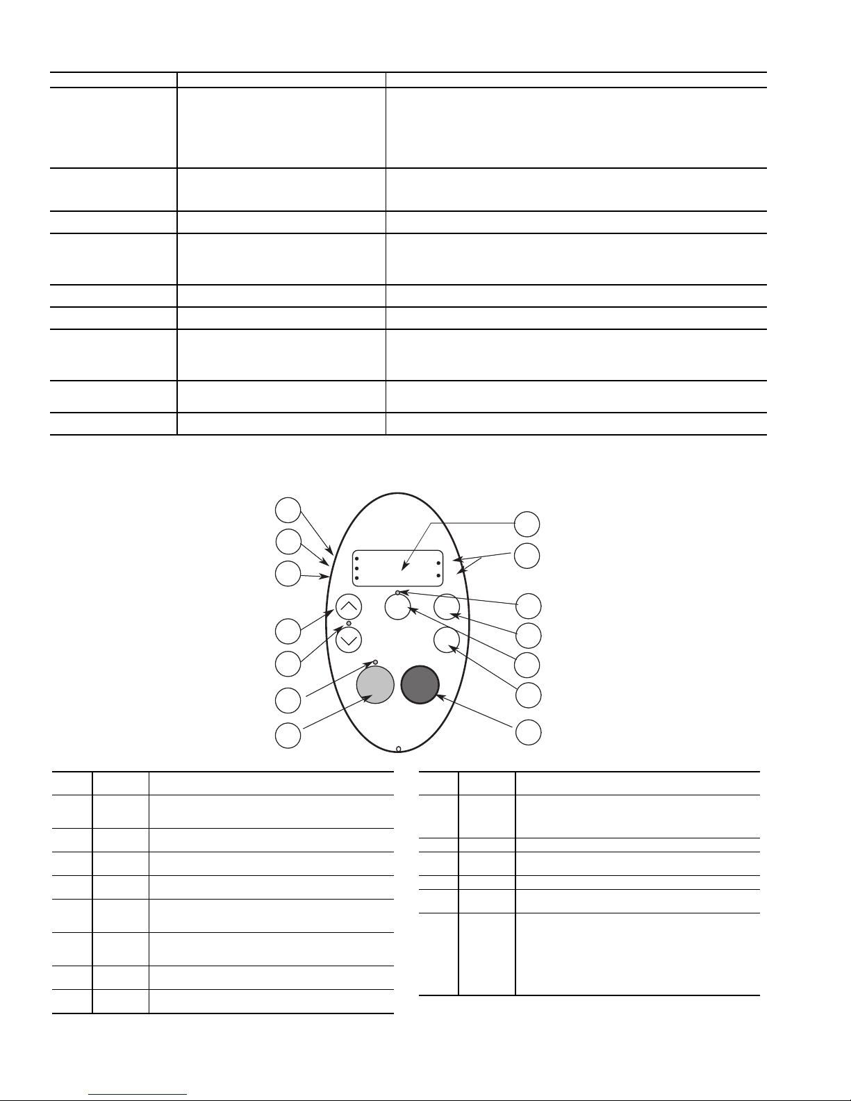
Table 42 — Siemens Low Ambient Temperature Controller Alarm Messages
Fig. 37 — Schnieder Altivar 21 VFD Display Panel
CALL
OUT
LED/KEY DESCRIPTION
1
Display
RUN LED
Illuminates when a run command is applied to the drive
controller. Flashes when a speed reference is present
with the run command.
2
Display
PRG LED
Illuminates when Programming mode is active. Flashes
when -GrU menus are active.
3
Display
MON LED
Illuminates when Monitoring mode is active. Flashes in
fault record display mode.
4
Display
Unit
4 digits, 7 segments
5
Display
Unit LED
The % LED illuminates when a displayed numeric
value is a percentage. The Hz LED illuminates when a
displayed numeric value is in hertz.
6
Up/Down
arrows
Depending on the mode, use the arrows to: navigate
between the menus, change a value, or change the
speed reference when Up/Down LED (7) is lit.
7
Up/Down
LED
Illuminates when the Up/Down arrows are controlling
the speed reference.
8
Loc/Rem
LED
Illuminates when Local mode is selected.
CALL
OUT
LED/KEY DESCRIPTION
9
MODE Press to select the Keypad mode. Modes are: Run
mode (default on power-up), Programming mode, and
Monitoring mode. Can also be used to go back to the
previous menu.
10 Loc/Rem Switches between Local and Remote modes.
11
ENT Press to display a parameter’s value or to save a
changed value.
12 RUN LED Illuminates when the Run key is enabled.
13
RUN Pressing this key when the RUN LED is illuminated
starts the drive controller.
14
STOP Stop/reset key. In Local mode, pressing the STOP key
causes the drive controller to stop based on the setting
of parameter F721. In Remote mode, pressing the
STOP key causes the drive controller to stop based on
the setting of parameter F603. The display will indicate
a flashing “E”. If F735 is set to 0 (default setting), pressing the stop key twice will reset all resettable faults if
the fault condition has been resolved.
FAU LT POSSIBLE CAUSES TROUBLESHOOTING
A0501
Current Limit
A0502
Overvoltage Limit
A0503
Undervoltage Limit
A0504
Drive
Overtemperature
A0505
Drive I2t
A0506
Drive Duty Cycle
A0511
Motor
Overtemperature I
A0541
Motor Data
Identification Active
A0600
RTOS Overrun Warning
LEGEND
I2t—Current Squared Time
RTOS — Run Time Operating System
• Motor power does not correspond to the
drive power
• Motor leads are too short
• Ground fault
• Mains supply too high
• Load regenerative
• Ramp-down time too short
• Mains supply too low
• Short mains interruption
Warning level of inverter heat-sink temperature
(P0614) is exceeded, resulting in pulse frequency reduction and/or output frequency
reduction (depending on parameters set
(P0610)
Warning level is exceeded; current will be
reduced if parameters set (P0610 = 1)
Heatsink temperature and thermal junction
model are outside of allowable range
Motor overloaded Check the following:
2
t
Motor data identification (P1910) selected or
running
Software error —
1. Check whether the motor power corresponds to the drive power
2. Check that the cable length limits have not been exceeded
3. Check motor cable and motor for short-circuits and ground faults
4. Check whether the motor parameters correspond with the motor being used
5. Check the stator resistance
6. Increase the ramp-up-time
7. Reduce the boost
8. Check whether the motor is obstructed or overloaded
1. Check that mains supply voltage is within allowable range
2. Increase ramp down times
NOTE: If the vdc-max controller is active, ramp-down times will be automatically
increased
Check main supply voltage (P0210)
1. Check if ambient temperature is within specified limits
2. Check load conditions and duty cycle
3. Check if fan is turning when drive is running
Check if duty cycle is within specified limits
Check if duty cycle is within specified limits
2
1. P0611 (motor I
2. P0614 (motor I
3. Are long periods of operation at low speed occurring
4. Check that boost settings are not too high
Wait until motor identification is finished
t time constant) should be set to appropriate value
2
t overload warning level) should be set to suitable level
1
2
3
6
7
12
13
RUN
PRG
MON
RUN STOP
4
5
8
9
Loc
Rem
%
Hz
MODE
ENT
10
11
14
58
Page 59
Table 43 — Schnieder Altivar 21 VFD Operating Parameters
PARAMETER NAME VALUE
uLu Rated Motor Voltage Nominal motor voltage(V) from rating plate
F201 VIA Speed Reference Level 1 5
F202 VIA Output Frequency Level 1 0
F203 VIA Speed Reference Level 2 100
F204 VIA Output Frequency Level 2 60
F401 Slip compensation 60%
F415 Rated Motor Current Nominal motor current(A) from rating plate
F417 Rated Motor Speed Nominal motor speed(RPM) from rating plate
F701 Keypad display: % or A/V 1
tHr Motor Rated Current Overload Setting Nominal motor current(A) from rating plate
uL Rated Motor Frequency 60 Hz
FH Maximum Frequency 60 Hz
LL Low Speed 0 Hz
UL High Speed 60 Hz
ACC Ramp-up Time 10 Sec
dEC Ramp-down Time 10 Sec
cnod Remote Mode Start/Stop Control 0 (Control terminal logic inputs)
fnod
Remote Mode Primary Speed reference
Source
1 (VIA)
PRE-START-UP
IMPORTANT: Complete the Start-Up Checklist
for 30XA Liquid Chillers at the end of this publication.
The checklist assures proper start-up of a unit, and
provides a record of unit condition, application
requirements, system information, and operation at
initial start-up.
Do not attempt to start the chiller until the following checks
have been completed.
System Check
1. Check auxiliary components, such as the chilled fluid
circulating pump, air-handling equipment, or other
equipment to which the chiller supplies liquid are operational. Consult manufacturer’s instructions. If the unit has
field-installed accessories, be sure all are properly
installed and wired correctly. Refer to unit wiring
diagrams.
2. Open compressor suction service valves (if equipped).
3. Open discharge line, liquid line, oil line, and economizer
(if equipped) service valves.
4. Fill the chiller fluid circuit with clean water (with recommended inhibitor added) or other non-corrosive fluid to be
cooled. Bleed all air out of high points of system. If outdoor temperatures are expected to be below 32 F (0° C),
and unit has a flooded cooler option, sufficient inhibited
propylene glycol or other suitable corrosion inhibited antifreeze should be added to the chiller water circuit to prevent possible freeze-up.
The chilled water loop must be cleaned before the unit is
connected. Units supplied with the accessory hydronic
package include a run-in screen. If the run-in screen is left
in the suction guide/strainer, it is recommended that the
Service Maintenance be set to alert the operator within
24 hours of start-up to be sure that the run-in screen in the
suction guide/strainer is removed. To set the time for the
parameter, go to Water Filter Ctrl (days), W.FIL. Val-
ues for this item are counted as days. Refer to the hydronic pump package literature if unit is equipped with the
optional hydronic pump package.
5. Check tightness of all electrical connections.
6. Electrical power source must agree with unit nameplate.
7. Oil separator heaters must be firmly seated under the oil
separator, and must be energized for 24 hours prior to
start-up.
8. Verify power supply phase sequence. Fan motors are 3
phase. Check rotation of non low-ambient controlled fans
by using the quick test. Fan rotation is counterclockwise
as viewed from top of unit. If fan is not turning counterclockwise, reverse 2 of the power wires at the main terminal block.
9. Perform service test to verify proper operation.
START-UP
CAUTION
Do not manually operate contactors. Serious damage to the
machine may result.
Actual Start-Up —
under supervision of a qualified refrigeration technician.
1. Be sure all oil, suction valves, discharge valves (if
equipped) and liquid line service valves are open.
2. Using the unit control, set leaving-fluid set point (Cool-
ing Setpoint 1, CSP.1). No cooling range adjustment is
necessary.
3. If optional control functions or accessories are being
used, the unit must be properly configured. Refer to
Configuration Options section for details.
4. Start the chilled fluid pump, if unit is not configured for
pump control. (Cooler Pumps Sequence, PUMP=0)
5. Complete the Start-Up Checklist to verify all components
are operating properly.
6. If unit is equipped with navitgator turn Enable/Off/Remote
contact switch to Enable position. If unit is equipped with
Touch Pilot press the Start/Stop button and select Local On.
7. Allow unit to operate and confirm that everything is
functioning properly. Check to see that leaving fluid
temperature agrees with leaving set point Control Point
(Control Point, CTPT).
Actual start-up should be done only
59
Page 60
Operating Limitations
TEMPERATURES — Unit operating temperature limits are
listed in the table below.
TEMPERATURE F C
Maximum Ambient Temperature 125 52
Minimum Ambient Temperature 32 0
Maximum Cooler EWT* 95 35
Maximum Cooler LWT 60 15
Minimum Cooler LWT† 40 4.4
LEGEND
EWT — Entering Fluid (Water) Temperature
LWT — Leaving Fluid (Water) Temperature
*For sustained operation, EWT should not exceed 70 F (21.1 C).
†Unit requires brine modification for operation below this
temperature.
Low Ambient Temperature Operation — If unit operating
temperatures below 32 F (0° C) are expected, refer to separate
unit installation instructions for low ambient temperature operation using accessory low ambient temperature head pressure
control, if not equipped. Contact your Carrier representative for
details.
NOTE: If wind velocity is expected to be greater than 5 mph
(8 km/h) wind baffles and brackets must be field-fabricated
and installed for all units using accessory low ambient head
pressure control. See the 30XA Installation Instructions or the
low ambient temperature head pressure control accessory
installation instructions for more information.
CAUTION
Brine duty application (below 40 F [4.4 C] LCWT) for
chiller normally requires factory modification. Contact a
Carrier Representative for details regarding specific
applications. Operation below 40 F (4.4 C) LCWT without modification can result in compressor failure.
VOLTAGE
Main Power Supply — Minimum and maximum acceptable
supply voltages are listed in the Installation Instructions.
Unbalanced 3-Phase Supply Voltage — Never operate a motor
where a phase imbalance between phases is greater than 2%.
To determine percent voltage imbalance:
max voltage deviation from
% Voltage Imbalance = 100 x
The maximum voltage deviation is the largest difference
between a voltage measurement across 2 legs and the average
across all 3 legs.
Example: Supply voltage is 240-3-60.
AB = 243v
BC = 236v
AC = 238v
avg voltage
average voltage
1. Determine average voltage:
Average voltage =
243+236+238
717
=
3
3
= 239
2. Determine maximum deviation from average voltage:
(AB) 243 – 239 = 4 v
(BC) 239 – 236 = 3 v
(AC) 239 – 238 = 1 v
Maximum deviation is 4 v.
3. Determine percent voltage imbalance:
% Voltage Imbalance = 100 x
4
239
= 1.7%
This voltage imbalance is satisfactory as it is below the
maximum allowable of 2%.
IMPORTANT: If the supply voltage phase imbalance is more than 2%, contact the local electric
utility company immediately. Do not operate unit
until imbalance condition is corrected.
MINIMUM FLUID LOOP VOLUME — To obtain proper
temperature control, loop fluid volume must be at least 3 gallons per ton (3.25 L per kW) of chiller nominal capacity for air
conditioning and at least 6 gallons per ton (6.5 L per kW) for
process applications or systems that must operate at low ambient temperatures (below 32 F [0° C]). Refer to application information in Product Data literature for details.
FLOW RATE REQUIREMENTS — Standard chillers should
be applied with nominal flow rates within those listed in the
Minimum and Maximum Cooler Flow Rates table. Higher or
lower flow rates are permissible to obtain lower or higher
temperature rises. Minimum flow rates must be exceeded to
assure turbulent flow and proper heat transfer in the cooler. See
Table 44. See Fig. 38A-38D for cooler pressure drop curves.
CAUTION
Operation below minimum flow rate could generate
alarms, which could result in damage to the cooler.
Consult application data section in the Product Data
literature and job design requirements to determine flow rate
requirements for a particular installation.
60
Page 61
Table 44 — 30XA Minimum and Maximum Cooler Flow Rates
Cooler Leaving Water Temperature* 40 F (4.4 C) 60 F (15 C)
30XA
UNIT SIZE
80 180.4 11.4
82 172.8 10.9 DX Cooler — 86 5.4 346 21.8
90 201.9 12.7
92 193.7 12.2 DX Cooler — 97 6.1 387 24.4
100 225.5 14.2
102 214.3 13.5 DX Cooler — 107 6.7 429 27.0
110 244.9 15.5
112 235.2 14.8 DX Cooler — 118 7.4 470 29.6
120 264.8 16.7
122 254.7 16.0 DX Cooler — 127 8.0 509 32.1
140 317.8 20.1
142 303.5 19.1 DX Cooler — 152 9.6 607 38.2
160 365.1 23
162 347 21.9 DX Cooler — 174 10.9 694 43.7
180 409.6 25.8
182 401.7 25.3 DX Cooler — 201 12.6 803 50.6
200 463.9 29.3
202 447.1 28.2 DX Cooler — 224 14.1 894 56.3
220 505.9 31.9
222 493 31.1 DX Cooler — 246 15.5 950 59.9
240 545.8 34.4
242 530 33.5 DX Cooler — 265 16.7 950 59.9
260 600.3 37.9
262 583 36.8 DX Cooler — 292 18.4 950 59.9
280 642.2 40.5
282 627 39.5 DX Cooler — 313 19.8 950 59.9
300 687.5 43.4
302 665 42.0 DX Cooler — 333 21.0 1331 83.9
325 733.4 46.3
327 720 45.4 DX Cooler — 360 22.7 1440 90.8
350 775.4 48.9
352 757 47.8 DX Cooler — 379 23.9 1514 95.5
400 917.6 57.9
450 1019.3 64.3
500 1092.8 68.9
Nominal Flow Rate
(gpm) (L/s) (gpm) (L/s) (gpm) (L/s)
LEGEND
DX — Direct Expansion
*For applications requiring cooler leaving water temperature operation at less than
40 F (4.4 C), the units require the use of antifreeze and application may require
the brine option. Contact your local Carrier representative for more information.
†For applications requiring cooler entering water temperature operation at less
than 45 F (7.2 C), contact your local Carrier representative for unit selection using
the Carrier electronic catalog.
Cooler Entering Water Temperature† 45 F (7.2 C) 70 F (21.1 C)
ITEM MINIMUM MAXIMUM
Cooler
Standard, Flooded 2 95 6 379 23.9
Plus One Pass, Flooded 3 43 2.7 192 12.1
Minus One Pass, Flooded 1 196 12.4 782 49.3
Standard, Flooded 2 101 6.4 403 25.4
Plus One Pass, Flooded 3 43 2.7 200 12.6
Minus One Pass, Flooded 1 229 14.4 917 57.9
Standard, Flooded 2 101 6.4 403 25.4
Plus One Pass, Flooded 3 43 2.7 200 12.6
Minus One Pass, Flooded 1 229 14.4 917 57.9
Standard, Flooded 2 125 7.9 501 31.6
Plus One Pass, Flooded 3 61 3.8 244 15.4
Minus One Pass, Flooded 1 254 16 1014 64
Standard, Flooded 2 125 7.9 501 31.6
Plus One Pass, Flooded 3 73 4.6 293 18.5
Minus One Pass, Flooded 1 281 17.7 1124 70.9
Standard, Flooded 2 134 8.5 538 33.9
Plus One Pass, Flooded 3 73 4.6 293 18.5
Minus One Pass, Flooded 1 324 20.4 1296 81.8
Standard, Flooded 2 165 10.4 660 41.6
Plus One Pass, Flooded 3 98 6.2 391 24.7
Minus One Pass, Flooded 1 354 22.3 1418 89.5
Standard, Flooded 2 202 12.7 807 50.9
Plus One Pass, Flooded 3 73 4.6 391 24.7
Minus One Pass, Flooded 1 416 26.2 1662 104.9
Standard, Flooded 2 223 14.1 892 56.3
Plus One Pass, Flooded 3 98 6.2 391 24.7
Minus One Pass, Flooded 1 458 28.9 1833 115.6
Standard, Flooded 2 235 14.8 941 59.4
Plus One Pass, Flooded 3 122 7.7 489 30.9
Minus One Pass, Flooded 1 501 31.6 2004 126.4
Standard, Flooded 2 266 16.8 1063 67.1
Plus One Pass, Flooded 3 147 9.3 587 37
Minus One Pass, Flooded 1 538 33.9 2151 135.7
Standard, Flooded 2 257 16.2 1027 64.8
Plus One Pass, Flooded 3 141 8.9 562 35.5
Minus One Pass, Flooded 1 584 36.8 2334 147.3
Standard, Flooded 2 293 18.5 1173 74
Plus One Pass, Flooded 3 141 8.9 562 35.5
Minus One Pass, Flooded 1 620 39.1 2481 156.5
Standard, Flooded 2 327 20.6 1308 82.5
Plus One Pass, Flooded 3 174 11 697 44
Minus One Pass, Flooded 1 687 43.3 2750 173.5
Standard, Flooded 2 361 22.8 1442 91
Plus One Pass, Flooded 3 211 13.3 843 53.2
Minus One Pass, Flooded 1 724 45.7 2897 182.8
Standard, Flooded 2 379 23.9 1516 95.6
Plus One Pass, Flooded 3 244 15.4 978 61.7
Minus One Pass, Flooded 1 767 48.4 3068 193.6
Standard, Flooded 1 501 31.6 2004 126.4
Plus One Pass, Flooded — — — — —
Minus One Pass, Flooded — — — — —
Standard, Flooded 1 501 31.6 2004 126.4
Plus One Pass, Flooded — — — — —
Minus One Pass, Flooded — — — — —
Standard, Flooded 1 501 31.6 2004 126.4
Plus One Pass, Flooded — — — — —
Minus One Pass, Flooded — — — — —
Number of
Passes
NOTES:
1. The 30XA units will start and pull down with loop temperatures up to 95 F (35 C).
2. Nominal flow rates required at AHRI conditions 44 F (7 C) leaving fluid temperature, 54 F (12 C) entering water temperature, 95 F (35 C) ambient. Fouling factor
0.00010 ft
3. To obtain proper temperature control, cooler loop fluid volume must be at least
3 gal/ton (3.23 L/kW) of chiller nominal capacity for air conditioning and at least
6 gal/ton (6.5 L/kW) for process applications or systems that must operate in low
ambient temperatures (below 32 F [0° C]).
Minimum Flow Rate Maximum Flow Rate
2
-hr-F/Btu (0.000018 m2-K/kW).
61
Page 62
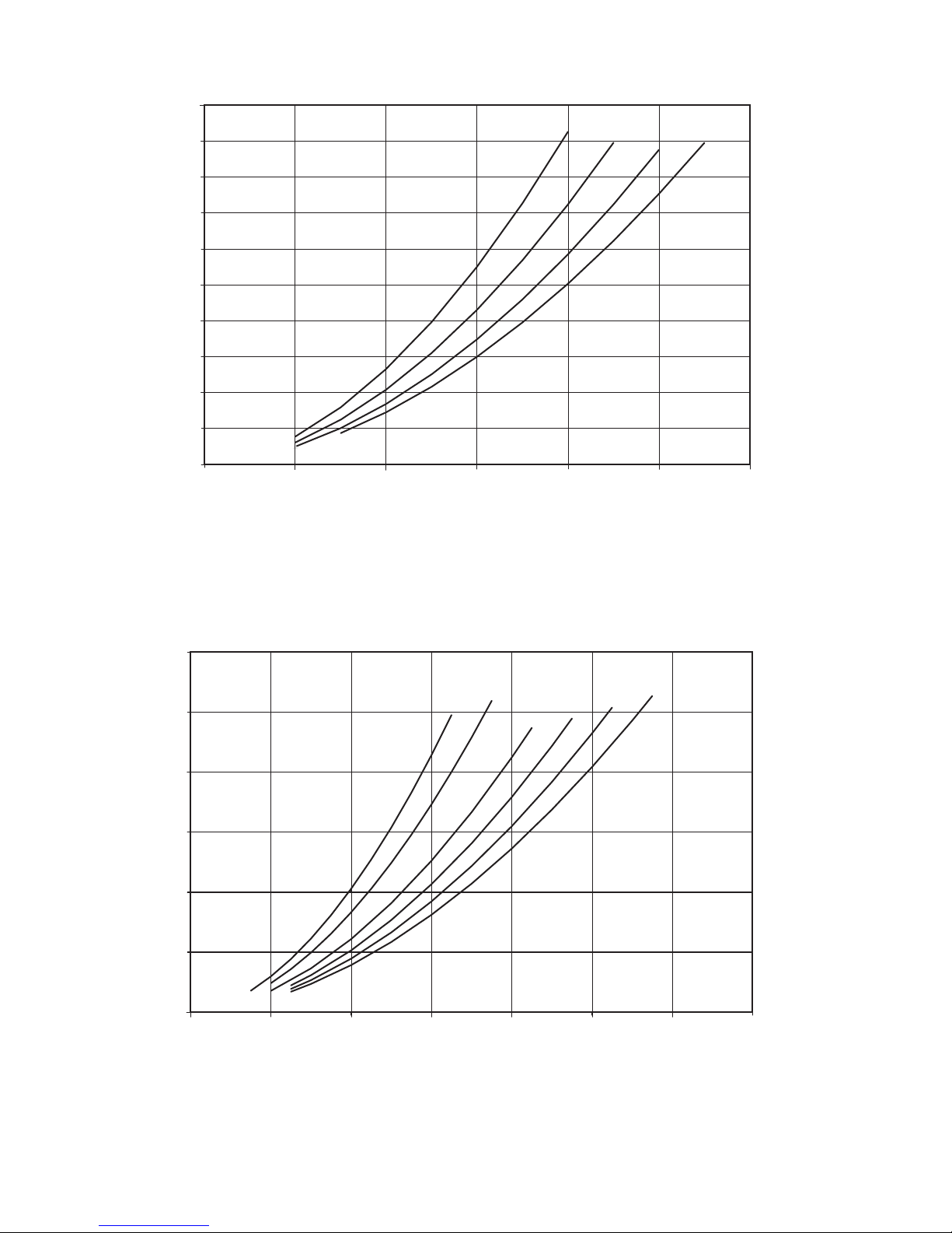
0
50
(149.5)
0
Cooler Flow, GPM (l/s)
Pressure Drop, ft wg (kPa)
080
090,100
110
120
45
(134.6)
40
(119.6)
35
(104.7)
30
(89.7)
25
(74.8)
20
(59.8)
15
(44.9)
10
(29.9)
5
(15)
100
(6.3)
200
(12.6)
300
(18.9)
400
(25.2)
500
(31.6)
600
(37.9)
Unit Sizes 30XA080, 90, 100, 110, 120
Unit Sizes 30XA140, 160, 180, 200, 220, 240
Fig. 38A — Cooler Pressure Drop Curves, Standard Pass Flooded Cooler
a30-4233
a30-4256
(179.4)
50
(149.5)
40
(119.6)
(89.7)
(59.8)
Pressure Drop, ft wg (kPa)
(29.9)
60
30
20
10
0
0
200
(12.6)
400
(25.2)
600
(37.9)
140
160
(50.5)
800
180
200
1000
(63.1)
220
240
1200
(75.7)
1400
(88.3)
Cooler Flow, GPM (l/s)
62
Page 63
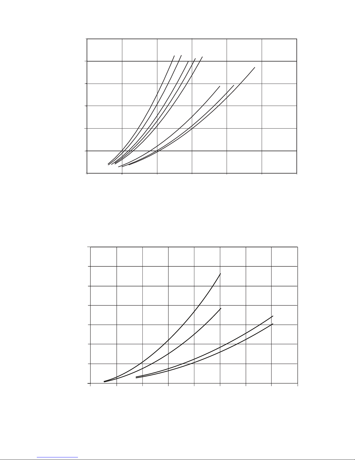
0
0
260
280
300
325
350
400
450
500
Pressure Drop, ft wg (kPa)
60
(179.4)
50
(149.5)
40
(119.6)
30
(89.7)
20
(59.8)
10
(29.9)
500
(31.6)
1000
(63.1)
1500
(94.6)
2000
(126.2)
2500
(157.7)
3000
(189.3)
Cooler Flow, GPM (l/s)
0
10
20
30
40
50
60
70
0 100 200 300 400 500 600 700 800
Pressure Drop, ft wg (kPa)
Cooler Flow, GPM (l/s)
(12.62)
(25.24) (37.85) (50.47)(6.31) (18.93)(31.55) (44.16)
(29.9)
(59.8)
(89.7)
(119.6)
(149.5)
(179.4)
(209.3)
112, 122
082, 092, 102
182, 202
142, 162
Unit Sizes 30XA260, 280, 300, 325, 350, 400, 450, 500
Fig. 38A — Cooler Pressure Drop Curves, Standard Pass Flooded Cooler (cont)
a30-4257
Unit Sizes 30XA082, 092, 102, 112, 122, 142, 162, 182, 202
a30-5308
Fig. 38B — Cooler Pressure Drop Curves, DX (Direct Expansion) Cooler
63
Page 64
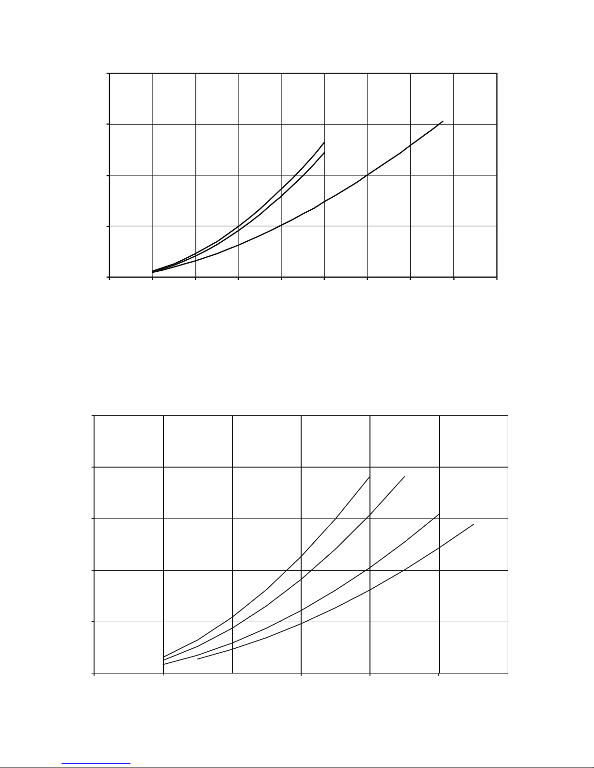
0
50
(149)
100
(299)
150
(488)
200
(598)
250
(747)
0 100
(6.3)
200
(12.6)
300
(18.9)
400
(25.2)
500
(31.6)
600
(37.9)
Cooler Flow, GPM (l/s)
Pressure Drop, ft wg (kPa)
080
090,100
110
120
0
20
40
60
80
0 200 400 600 800 1000 1200 1400 1600 1800
Pressure Drop, wg (kPa)
Cooler Flow, GPM (l/s)
222, 242
262, 282
302, 327, 352
(12. 62)
(25. 24) (37.85) (50. 47) ( 75.71)(63.09) (88.32)
(59. 8)
(119. 6)
(179. 4)
(239. 1)
(100. 94) (113.56)
Fig. 38C — Cooler Pressure Drop Curves, Plus One-Pass Flooded Cooler
Unit Sizes 30XA080, 090, 100, 110, 120
a30-4486
a30-5393
Fig. 38B — Cooler Pressure Drop Curves, DX (Direct Expansion) Cooler (cont)
Unit Sizes 30XA222, 242, 262, 282, 302, 327, 352
64
Page 65
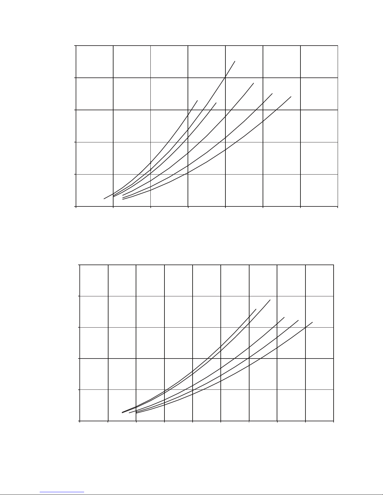
0
50
(149)
100
(299)
150
(488)
200
(598)
250
(747)
0 200
(12.6)
400
(25.2)
600
(37.9)
800
(50.6)
1000
(63.3)
1200
(75.9)
1400
(88.6)
1600
(101.3)
1800
(114.0)
COOLER FLOW, GPM (l/s)
Pressure Drop, ft wg (kPa)
260
280
300
325
350
NOTE: Plus-one-pass coolers are not available for 30XA400-500 units.
Fig. 38C — Cooler Pressure Drop Curves, Plus One-Pass Flooded Cooler (cont)
Unit Sizes 30XA260, 280, 300, 325, 350
a30-4489
250
Unit Sizes 30XA140, 160, 180, 200, 220, 240
a30-4487
(747)
180
200
(598)
150
(488)
100
(299)
Pressure Drop, ft wg (kPa)
50
(149)
0
0 200
(12.6)
400
(25.2)
140
600
(37.9)
COOLER FLOW, GPM (l/s)
160
(50.6)
800
200
1000
(63.3)
220
240
1200
(75.9)
1400
(88.6)
65
Page 66
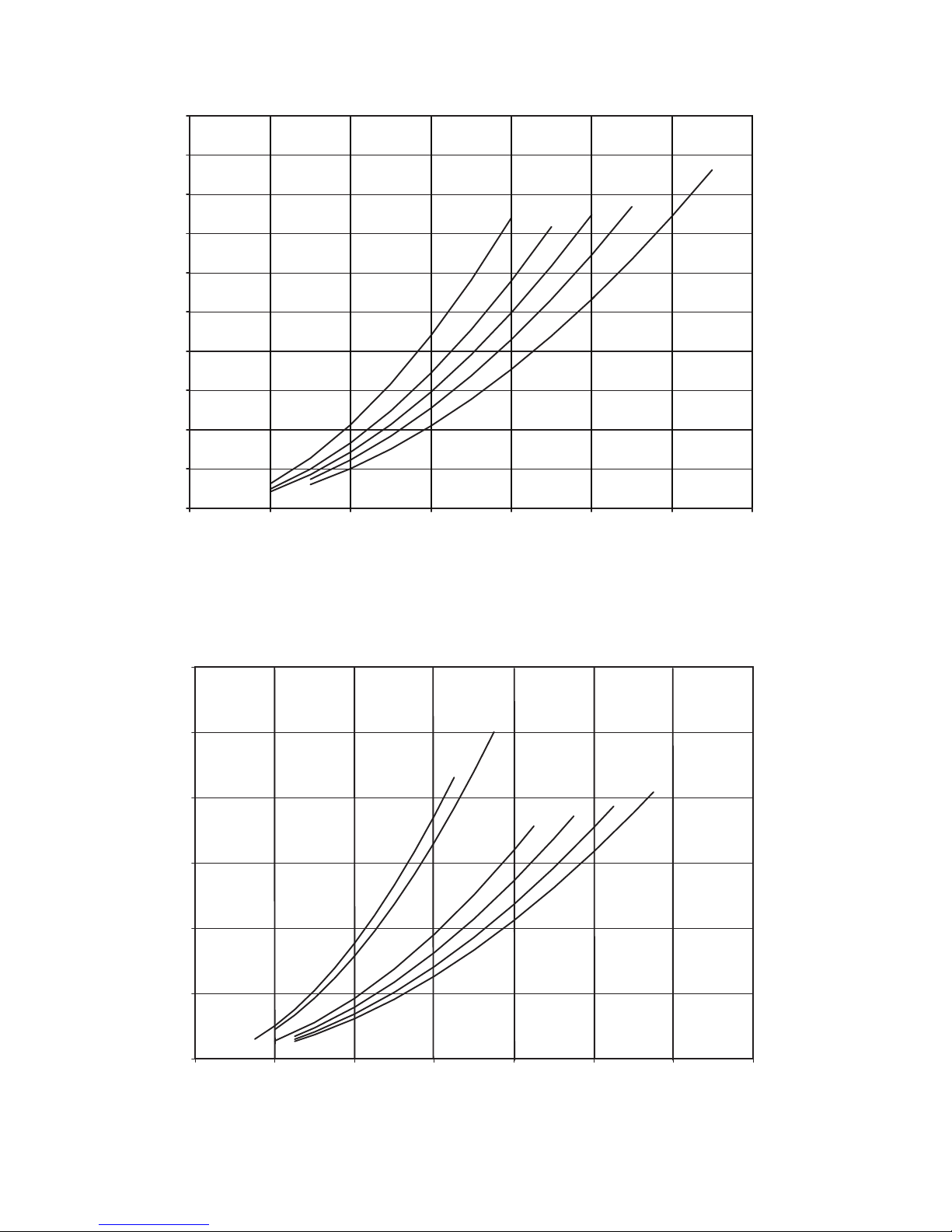
0
2
(5.3)
4
(11.6)
6
(17.4)
8
(23.2)
10
(29.9)
12
(35.7)
0200
(12.6)
400
(25.2)
600
(37.9)
800
(50.6)
1000
(63.3)
1200
(75.9)
1400
(88.6)
COOLER FLOW, GPM (l/s)
Pressure Drop, ft wg (kPa)
140
160
180
200
220
240
NOTE: Minus-one-pass coolers are not available for 30XA400-500 units.
Fig. 38D — Cooler Pressure Drop Curves, Minus One-Pass Flooded Cooler
Unit Sizes 30XA140, 160, 180, 200, 220, 240
a30-4491
0
1
(2.9)
2
(5.8)
3
(8.7)
4
(11.6)
5
(14.5)
6
(17.4)
7
(20.3)
8
(23.2)
9
(26.1)
10
(29.9)
0100
(6.3)
200
(12.6)
300
(18.9)
400
(25.2)
500
(31.6)
600
(37.9)
700
(44.2)
COOLER FLOW, GPM (l/s)
Pressure Drop, ft wg (kPa)
080
090,100
110
120
140
Unit Sizes 30XA080, 090, 100, 110, 120, 140
a30-4490
66
Page 67
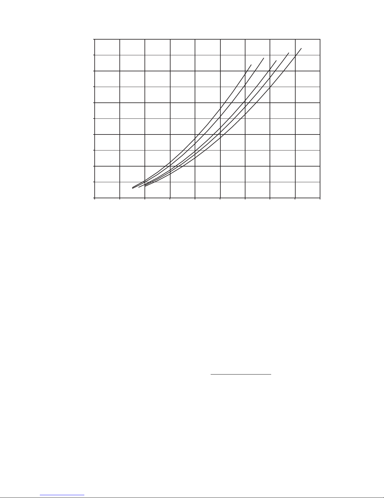
0
1
(2.9)
2
(5.5)
3
(8.7)
4
(11.6)
5
(14.5)
6
(17.4)
7
(20.3)
8
(23.2)
9
(26.1)
10
(29.9)
0200
(12.6)
400
(25.2)
600
(37.9)
800
(50.6)
1000
(63.3)
1200
(75.9)
1400
(88.6)
1600
(101.3)
1800
(114.0)
COOLER FLOW, GPM (l/s)
Pressure Drop, ft wg (kPa)
260
280 300
325
350
Unit Sizes 30XA260, 280, 300, 325, 350
NOTE: Minus-one-pass coolers are not available for 30XA400-500 units.
Fig. 38D — Cooler Pressure Drop Curves, Minus One-Pass Flooded Cooler (cont)
a30-4492
OPERATION
Sequence of Operation —
the chiller, the cooler pump will start. After verifying water
flow, the control will monitor the entering and leaving water
temperature. If the need for mechanical cooling is determined,
the control decides which circuit and compressor to start. The
control will start the required compressor completely unloaded
and deenergize the oil separator heater (if already energized).
The control will continue to load this circuit by moving the
slide valve to satisfy cooling requirements. Once fully loaded,
the control will start additional circuits to satisfy the load as
required. Shutdown of each circuit under normal conditions
occurs in the opposite sequence to loading. Once the A circuit
is fully unloaded the compressor is shut off and the EXV will
close completely.
If the outside-air temperature is less than the brine freeze
point plus 17º F (9.4º C) then the circuit will perform a pump
down cycle. The EXV will be closed and the compressor continues to operate until the saturated suction temperature (SST)
is 10º F (5.6º C) lower than the starting SST or 10º F (5.6º C)
less than the brine freeze point. Once the compressor is shut off
the actuated ball valve (located in the discharge line) will be
closed if equipped (flooded cooler option units only).
ACTUATED BALL VALVE (ABV), FLOODED COOLER
ONLY — There is either one or two discharge ABVs located
in the discharge line of each circuit of the unit. See Fig. 39 for a
typical ABV assembly with enclosure. The ABV is a motorized ball valve, which is used to close the discharge line to prevent refrigerant migrating from condenser to the cooler when
the circuit is off. The valve will be opened before the compressor is started and will normally close when pressure equalizes
between suction and discharge lines. If the outside air temperature is less than the brine freeze point plus 17º F (9.4º C) then
With a command to start
the valve will close immediately without waiting for pressure
equalization.
The actuated ball valves are linked to the cooler heater oper-
ation in the controls. Cooler Heater option (Configuration
Unit CO.HT , SERVICE FACTORY Cooler Heater
Select) must be enabled for the Actuated Ball Valve to operate.
See Fig. 40 for a view of a fully open ball valve with the actuator removed. The flat surface at the top of the valve shaft is
parallel to the discharge line. The ball valve motor mounting
plate should be perpendicular to the discharge line at all times.
If not, adjust it by loosening the set screw on the side of the
valve, reposition assembly and tighten set screw.
See Fig. 41 for a view of the ball valve motor mounting
with a fully open valve. The motor actuator arm should be at a
counterclockwise position, with the valve shaft in a parallel position. If not in a parallel position, loosen the clamping screw
and push the disengagement button to rotate the actuator arm
until it stops. Retighten the clamping screw.
ABV Manual Operation
— The ABV can be operated manually as a discharge service valve by completing the following
steps:
1. Remove the actuator cover.
2. With the compressor off hold down the Push button.
3. Close the ABV by turning the shaft adapter by hand or
with a wrench so that the flats on the end of the shaft are
perpendicular to the discharge line.
4. Release the Push button.
5. Disconnect the control power cable to the ABV.
67
Page 68
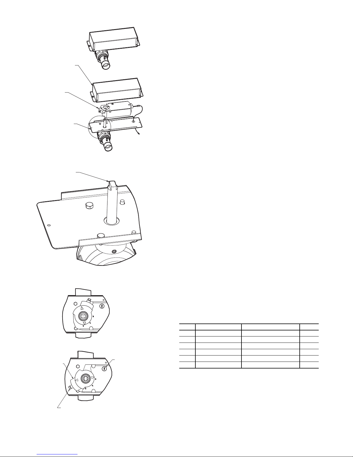
BASE PLATE
VALVE MOTOR
VALVE MOTOR COVER
VALVE SHAFT
CLAMPING SCREW
ACTUATOR ARM
DISENGAGEMENT
BUTTON
MOUNTING - FULLY CLOSED
MOUNTING - FULLY OPEN
Fig. 39 — Typical ABV Assembly with Enclosure
Fig. 40 — Fully Open Ball Valve
with Actuator Removed
Fig. 41 — Ball Valve Motor
a30-4236
a30-4237
a30-4238
Dual Chiller Sequence of Operation — With a com-
mand to start the chiller, the master chiller determines which
chiller will become the lead chiller based on the configuration
of Lead Lag Select, LLBL and Lead/Lag Balance Data,
LLBD. The lead chiller is always started first and the lag chiller
is held at zero percent capacity by the master chiller forcing the
lag demand limit value to 0%. If Lead Pulldown Time (Lead
Pulldown Time, LPUL) has been configured, the lead chiller
will continue to operate alone for that specified time. After the
Lead Pulldown Time timer has elapsed and when the lead chiller is fully loaded, either all available compression is on or at the
master demand limit value, then the lag start timer (Lag Start
Timer, LLDY) is initiated. When the pulldown timer and lag
start timer has elapsed and the Combined Leaving Chilled Water Temperature is more than 3° F (1.7° C) above the set point,
then the lag chiller is started. If the lag chiller’s water pump
was not started when the machines went into occupied mode,
the lag chiller water pump will be started. The lag chiller will
start with the master chiller forcing the lag chiller demand limit
value (LAG_LIM) to the master’s demand limit value. If lead/
lag capacity balance is selected, once the lag chiller has started,
the master shall try to keep the difference in capacity between
lead and lag less than 20%. The master shall then be responsible for water loop capacity calculation, and will determine
which chiller, the lead or lag, will increase or decrease capacity.
When the load reduces, the lag chiller will be the first chiller to
unload. To accomplish this, the lead chiller set point is decreased by 4° F (–2.2° C) until the lag chiller unloads.
PUMP OPERATION — For parallel chiller pump operation,
the lead chiller’s water pump will be started. The lag chiller’s
water pump will be maintained off if Lag Unit Pump Control,
LAGP=0. The internal algorithm of lead chiller will control ca-
pacity of the lead chiller.
For series chiller operation, the pump is always controlled
by the master chiller.
Operating Modes — Operating modes are override
modes that affect normal operation of the equipment. More
than one operating mode can be in effect at the same time.
Some operating modes have corresponding capacity control
overrides in the Capacity Control Overrides section on
page 47.
For the Touch Pilot™ display, the status of the operating
modes can be found in the MODES submenu, which is under
the STATUS menu. Each operating mode and its status (Yes =
active, No = inactive) is listed.
For the Navigator™ display, the status of the operating
modes can be found in the MODE submenu under the OPER-
ATING MODES menu. The 6 top priority operating modes are
displayed in MD01 through MD06. To view the modes with
the Navigator display:
ITEM ITEM EXPANSION PATH VALUE
MD01 First Active Mode Operating modes
MD02 Second Active Mode Operating modes
MD03 Third Active Mode Operating modes
MD04 Fourth Active Mode Operating modes
MD05 Fifth Active Mode Operating modes
MD06 Sixth Active Mode Operating modes
MODE 0-32
MODE 0-32
MODE 0-32
MODE 0-32
MODE 0-32
MODE 0-32
See Table 45 for a list of operating modes.
STARTUP DELAY IN EFFECT — This mode is checked
for when the unit is started. This mode is active when the Minutes Off Time (Unit Off to On Delay, DELY) timer is active.
The unit will not start until the timer has expired. The mode
will terminate when the timer expires.
68
Page 69
NAVIGATOR OPERATING
MODE NUMBER
01 Star tup Delay in Effect Startup Delay in Effect 2 Yes/No
02 Second Setpoint in Use Second Setpoint in Use 3 Yes/No
03 Reset in Effect Reset in Effect 4 Yes/No
04 Demand Limit Active Demand Limit Active 5 Yes/No
05 Ramp Loading Active Ramp Loading Active 6 Yes/No
06 Cooler Heater Active Cooler Heater Active 7 Yes/No
07 Cooler Pumps Rotation Cooler Pumps Rotation 8 Yes/No
08 Pump Periodic Start Pump Periodic Start 9 Yes/No
09 Night Low Noise Active Night Low Noise Active 10 Yes/No
10 System Manager Active System Manager Active 11 Yes/No
11 Mast Slave Ctrl Active Mast Slave Active 12 Yes/No
12 Auto Changeover Active Auto Changeover Active 13 Yes/No
13 Free Cooling Active Free Cooling Active 14 Yes/No
14 Reclaim Active Reclaim Active 15 Yes/No
15 Electric Heat Active Electric Heat Active 16 Yes/No
16 Heating Low EWT Lockout Heating Low EWT Lockout 17 Yes/No
17 Condenser Pumps Rotation Condenser Pumps Rotation 18 Yes/No
18 Ice Mode in Effect Ice Mode in Effect 19 Yes/No
19 Defrost Active on Cir A Defrost Active on Cir A 20 Yes/No
20 Defrost Active on Cir B Defrost Active on Cir B 21 Yes/No
21 Low Suction Circuit A Low Suction Circuit A 22 Yes/No
22 Low Suction Circuit B Low Suction Circuit B 23 Yes/No
23 Low Suction Circuit C Low Suction Circuit C 24 Yes/No
24 High DGT Circuit A High DGT Circuit A 25 Yes/No
25 High DGT Circuit B High DGT Circuit B 26 Yes/No
26 High DGT Circuit C High DGT Circuit C 27 Yes/No
27 High Pres Override Cir A High Pres Override Cir A 28 Yes/No
28 High Pres Override Cir B High Pres Override Cir B 29 Yes/No
29 High Pres Override Cir C High Pres Override Cir C 30 Yes/No
30 Low Superheat Circuit A Low Superheat Circuit A 31 Yes/No
31 Low Superheat Circuit B Low Superheat Circuit B 32 Yes/No
32 Low Superheat Circuit C Low Superheat Circuit C 33 Yes/No
Table 45 — 30XA Operating Modes
NAVIGATOR EXPANSION TOUCH PILOT DISCRIPTION
TOUCH PILOT
LINE NUMBER
TOUCH PILOT
VAL UE
SECOND SETPOINT IN USE — This mode is checked for
when the unit is ON. The mode is active when Cooling Setpoint 2 (Cooling Setpoint 2, CSP.2) or Ice Setpoint (Cooling
Ice Setpoint, CSP.3) is in use. While in this mode, the Active
Setpoint (Current Setpoint, SETP) will show the CSP.2 or
CSP.3 value.
While in this mode, the unit will operate to the Cooling Setpoint 2 (CSP.2) or Ice Setpoint (CSP.3). The mode will termi-
nate when the Cooling Setpoint 2 (CSP.2) or Ice Setpoint
(CSP.3) is no longer in use.
RESET IN EFFECT — This mode is checked for when the
unit is ON. The mode will be active when Temperature Reset
(Cooling Reset Select, CRST) is enabled either by CRST=1
(Outside Air Temperature), CRST=2 (Return Water), CRST=3
(4-20 mA Input), or CRST=4 (Space Temperature) and reset is
active.
While in this mode, the Active Setpoint (Current Setpoint,
SETP) will be modified according to the programmed information and will be displayed as the Control Point (Control
Point, CTPT). The mode will terminate when the Temperature
Reset is not modifying the active leaving water set point, causing SETP to be the same as CTPT.
DEMAND LIMIT ACTIVE — This mode is chacked for
when the unit is ON. The mode is active when Demand Limit
(Demand Limit Type Select, DMDC) is enabled either by
DMDC=1 (Switch), DMDC=2 (4-20 mA Input), or the Night
Time Low Sound Capacity Limit (Capacity Limit, LS.LT).
The Active Demand Limit Value (Active Demand Limit
Va l, LIM) will display the current demand limit according to
the programmed information and the unit’s capacity will be reduced to the amount shown or lower. The mode will terminate
when the Demand Limit command has been removed.
RAMP LOADING ACTIVE — This mode is checked for
when the unit is ON. The mode is active when Ramp Loading
(Ramp Loading Select, RL.S) is enabled and the following
conditions are met:
1. The leaving water temperature is more than 4° F (2.2° C)
from the Control Point (
Control Point, CTPT), and
2. The rate of change of the leaving water temperature is
greater than the Cool Ramp Loading (Cooling Ramp
Loading, CRMP).
The control will limit the percent capacity increase until one
of the two conditions above are no longer met, then the mode
will terminate.
COOLER HEATER ACTIVE — This mode is checked for
whether the unit is ON or OFF. The mode is active when the
cooler heater is energized. The cooler heater is energized when
the Outdoor Air Temperature (External Temperature, OAT)
is less than the calculated value, (Freeze Setpoint + Cooler
Heater Delta T Setpoint [Cooler Heater Delta Spt, HTR] default – 2° F [1.1° C]) and either the Leaving Water Temperature
(Cooler Leaving Fluid, LWT) or the Entering Water Temperature (Cooler Entering Fluid, EWT) are less than or equal to
the Freeze Setpoint + Cooler Heater Delta T Setpoint (HTR).
The Freeze Setpoint is 34 F (1.1 C), for fresh water systems
(Cooler Fluid Type, FLUD=1). The Freeze Setpoint is Brine
Freeze Setpoint (Brine Freeze Setpoint, LOSP), for Medium
Temperature Brine systems (Cooler Fluid Type, FLUD=2).
When in this mode, the cooler heater will be energized. The
cooler heater will be deenergized when both the Entering Water Temperature (EWT) and Leaving Water Temperature
(LWT) are above the Freeze Setpoint + Cooler Heater Delta T
Setpoint (HTR).
This mode is enabled for freeze protection. If the temperatures are not as described above, check the accuracy of the outside air, entering and leaving water thermistors.
COOLER PUMPS ROTATION — This mode is checked for
whether the unit is ON or OFF. The mode is active when the
69
Page 70

Cooler Pump Sequence (Cooler Pump Run Status,
PUMP=2) (2 Pumps Automatic Changeover) and the Pump
Rotation Delta Timer (Pump Auto Rotation Delay, ROT.P)
have expired.
The control will switch the operation of the pumps. The
lead pump will operate normally. The lag pump will be started,
becoming the lead, and then the original lead pump will be shut
down. This mode will terminate when the pump operation has
been completed.
PUMP PERIODIC START — This mode is active when the
cooler pump is started due to the Periodic Pump Start configuration (Pump Sticking Protection, PM.PS=YES). If the pump
has not run that day, a pump will be started and will run for 2
seconds at 2:00 PM. If the machine is equipped with dual
pumps, Pump no. 1 will run on even days (such as day 2, 4, 6
of the month). Pump no. 2 will run on odd days (such as day 1,
3, 5 of the month). The mode will terminate when the pump
shuts down.
NIGHT LOW NOISE ACTIVE — This mode is active when
the Night Time Low Noise Option has been configured and the
current time is within the configured time frame. Programming
a Night Low Noise Start Time (Start Ho ur, LS.ST) and a
Night Low Noise End Time (End Hour, LS.ND) configures
the option.
The control will raise the head pressure set point to reduce
the number of condenser fans on, thereby reducing the sound
level of the machine. Additionally, if the Night Time Low
Sound Capacity Limit (Start Hour, LS.LT) has been configured, the unit’s capacity will be limited to the programmed level. This mode will terminate once the Night Low Noise End
Time (LS.ND) has been reached.
SYSTEM MANAGER ACTIVE — This mode is checked
when the unit is ON or OFF. This mode is active if a System
Manager such as Building Supervisor, Chillervisor System
Manager, or another CCN device is controlling the machine.
When this mode is active, the machine will respond to the
specific commands received from the System Manager. The
mode will be terminated if the System Manager control is released.
MASTER SLAVE CONTROL ACTIVE — This mode is
checked for if the machine is ON. This mode is active if Master
Slave Control has been enabled. This occurs when two machines are programmed, one as the master (Master/Slave Se-
lect, MSSL=1 [Master]) and the other as a slave (Master/
Slave Select, MSSL=2 [Slave]).
Both the master and slave machines will respond to the capacity control commands issued by the master controller. This
may include control point changes and demand limit commands. This mode will terminate when Master Slave Control
has been disabled.
AUTO CHANGEOVER ACTIVE — This mode is not
supported.
FREE COOLING ACTIVE — This mode is not supported.
RECLAIM ACTIVE — This mode is not supported.
ELECTRIC HEAT ACTIVE — This mode is not supported.
HEATING LOW EWT LOCKOUT — This mode is not
supported.
CONDENSER PUMPS ROTATION — This mode is not
supported.
ICE MODE IN EFFECT — This mode is checked for when
the unit is ON. This mode is active when Ice Setpoint (Cooling
Ice Setpoint, CSP.3) is in use. While in this mode, the Active
Setpoint (Current Setpoint, SETP) will show the Cooling Ice
Setpoint, CSP.3, value and the unit will operate to the Ice
Setpoint (
CSP.3). This mode will terminate when the Ice
Setpoint (CSP.3) is no longer in use.
DEFROST ACTIVE ON CIR A — This mode is not
supported.
DEFROST ACTIVE ON CIR B — This mode is not
supported.
LOW SUCTION CIRCUIT A
LOW SUCTION CIRCUIT B
LOW SUCTION CIRCUIT C — These modes are checked
when the circuit is ON. The appropriate circuit mode will be
active if one of the following conditions is true:
1. If the circuit’s saturated suction temperature (SST) is
more than 6° F (3.3° C) less than the freeze point and
both the cooler approach (Leaving Water Temperature –
SST) and superheat (Suction Gas Temperature – SST) are
greater than 15° F (8.3° C).
2. If the circuit is ON and the circuit’s SST is more than
18º F (10.0º C) below the freeze point for more than
90 seconds.
3. If the circuit’s saturated suction temperature is more
than 6° F (3.3° C) below the freeze point for more than
3 minutes.
For a fresh water system (Cooler Fluid Type, FLUD =1),
the freeze point is 34° F (1.1° C). For medium temperature
brine systems, (Cooler Fluid Type, FLUD=2), the freeze point
is Brine Freeze Set Point (Brine Freeze Setpoint, LOSP).
For criterion 1, no additional capacity will be added. For criteria 2 and 3 capacity will be decreased on the circuit. The
mode will terminate when the circuit’s SST is greater than the
freeze point minus 6° F (3.3° C) or the circuit has alarmed.
If this condition is encountered, see Possible Causes for
Alarms 56-58 on page 98.
HIGH DGT CIRCUIT A — This mode is not supported.
HIGH DGT CIRCUIT B — This mode is not supported.
HIGH DGT CIRCUIT C — This mode is not supported.
HIGH PRES OVERRIDE CIR A
HIGH PRES OVERRIDE CIR B
HIGH PRES OVERRIDE CIR C — This mode is checked
for when the circuit is ON. The appropriate circuit mode will
be active if the discharge pressure for the circuit, Discharge
Pressure Circuit A (Discharge Pressure, DP.A), Discharge
Pressure Circuit B (Discharge Pressure, DP.B), or Discharge
Pressure Circuit C (Discharge Pressure, DP.C), is greater than
the High Pressure Threshold (High Pressure Threshold,
HP.TH).
The capacity of the affected circuit will be reduced. Two
minutes following the capacity reduction, the circuit’s saturated
condensing temperature (SCT
affected circuit will not be allowed to add capacity for at least 5
) is calculated and stored. The
t+2
minutes following the capacity reduction. If after 5 minutes,
the circuit’s saturated condensing temperature is less than
SCT
–3° F (1.7° C), and then if required, percent capacity
t+2
will be added. If additional capacity is required, the control will
look for other circuits to add capacity.
This mode will terminate once the circuit’s saturated condensing temperature is less than SCT
–3° F (1.7° C).
t+2
If this condition is encountered, see Possible Causes for
Alarm A1.03. on page 103.
LOW SUPERHEAT CIRCUIT A
LOW SUPERHEAT CIRCUIT B
LOW SUPERHEAT CIRCUIT C — This mode is checked
for when the circuit is ON. The appropriate circuit mode will
be active if the circuit’s superheat (discharge gas temperature –
SCT) is less than 18° F (10° C).
70
Page 71
No additional capacity will be added until the circuit’s superheat is greater than 18° F (10° C). The control will look for
other circuits to add capacity if additional steps of capacity are
required. This mode will terminate once the affected circuit’s
superheat is greater than 18° F (10° C).
If this condition is encountered, see Possible Causes for
Alarms P.11, P.12 and P.13 on page 98.
Sensors — The electronic control uses up to 17 thermistors
to sense temperatures and up to 12 transducers to sense
pressure for controlling chiller operation. These sensors are
outlined below.
THERMISTORS (Tables 46-47B) — Thermistors that are
monitoring the chiller’s operation include: Cooler Entering
Water, Cooler Leaving Water, Dual Chiller Leaving Water,
Compressor Suction Gas Temperature, Compressor Discharge
Gas Temperature, Economizer Temperature, Compressor Motor
Temperature, and Outdoor Air Temperature Thermistors. These
thermistors are 5 kat 77 F (25 C) and are identical in temperature versus resistance. The Space Temperature Thermistor is
10 k at 77 F (25 C) and has a different temperature vs.
resistance.
Cooler Leaving Water Sensor
is installed in a friction fit well in the leaving water nozzle of
the cooler. See Fig. 42 and 43.
Cooler Entering Water Sensor
is factory-installed in a friction fit well in the entering water
nozzle of the cooler.
Suction Gas Temperature
factory-installed in a friction fit well located on the compressor
of each circuit. There is one thermistor for each circuit.
Compressor Discharge Gas Temperature
thermistor is factory-installed in a friction fit well located in the
discharge end of the compressor for the circuit. There is one
thermistor for each circuit.
Economizer Temperature
this thermistor is factory-installed in a friction fit well located
in the economizer line for the circuit. There is one thermistor
for each circuit.
Compressor Motor Temperature
istor is embedded in the motor windings. There are two thermistors in each compressor. One spare is provided.
Outdoor Air Temperature
to the back of the control box.
Remote Space Temperature
33ZCT55SPT) is a field-installed accessory mounted in the indoor space and is used for water temperature reset. The sensor
should be installed as a wall-mounted thermostat would be (in
— On all sizes, this thermistor
— On all sizes, this thermistor
— On all sizes, this thermistor is
— On all sizes, this
— On all sizes except 080 and 082,
— On all sizes, this therm-
— This sensor is factory-installed
— This sensor (part no.
the conditioned space where it will not be subjected to either a
cooling or heating source or direct exposure to sunlight, and 4
to 5 ft above the floor).
Space temperature sensor wires are to be connected to
terminals in the unit main control box. See Fig. 44. The space
temperature sensor includes a terminal block (SEN) and a RJ11
female connector. The RJ11 connector is used access into
the Carrier Comfort Network
®
(CCN) at the sensor.
To connect the space temperature sensor (see Fig. 44):
1. Using a 20 AWG twisted pair conductor cable rated for
the application, connect one wire of the twisted pair to
one SEN terminal and connect the other wire to the other
SEN terminal located under the cover of the space
temperature sensor.
2. Connect the other ends of the wires to terminals 7 and 8
on TB6 located in the unit control box.
Units on the CCN can be monitored from the space at the
sensor through the RJ11 connector, if desired. To wire the RJ11
connector into the CCN:
1. Cut the CCN wire and strip ends of the red (+), white
(ground), and black (–) conductors. (If another wire color
scheme is used, strip ends of appropriate wires.)
2. Insert and secure the red (+) wire to terminal 5 of the
space temperature sensor terminal block.
3. Insert and secure the white (ground) wire to terminal 4 of
the space temperature sensor.
4. Insert and secure the black (–) wire to terminal 2 of the
space temperature sensor.
IMPORTANT: The cable selected for the RJ11
connector wiring MUST be identical to the CCN
communication bus wire used for the entire network.
Refer to Table 14 for acceptable wiring.
5. Connect the other end of the communication bus cable to
the remainder of the CCN communication bus.
NOTE: The Energy Management Module (EMM) is required
for this accessory.
TRANSDUCERS — There are four pressure transducers per
circuit, and two different types of transducers: low pressure
(green connector) and high pressure (black connector).
Low Pressure Type: Suction Pressure Transducer (SPT), Economizer Pressure Transducer (EPT).
High Pressure Type: Discharge Pressure Transducer (DPT),
Oil Pressure Transducer (OPT). See Fig. 45A and 45B for
transducer locations.
THERMISTOR ID DESCRIPTION RESISTANCE AT 77 F (25 C) CONNECTION POINT
EWT Entering Water Thermistor 5k MBB-J6-CH2
LWT Leaving Water Thermistor 5k MBB-J6-CH1
OAT Outdoor Air Thermistor 5k MBB-J6-CH4
SGTA* Circuit A Suction Gas Thermistor 5k EXVA-J3-THA
SGTB* Circuit B Suction Gas Thermistor 5k EXVB-J3-THA
SGTC Circuit C Suction Gas Thermistor 5k EXVC-J3-THA
DGTA Circuit A Discharge Gas Thermistor 5k CPM-A-J9-CH02
DGTB Circuit B Discharge Gas Thermistor 5k CPM-B-J9-CH02
DGTC Circuit C Discharge Gas Thermistor 5k CPM-C-J9-CH02
ECTA Circuit A Economizer Thermistor 5k EXVA-J3-THB
ECTB Circuit B Economizer Thermistor 5k EXVB-J3-THB
ECTB Circuit C Economizer Thermistor 5k EXVC-J3-THB
DUAL Dual Chiller LWT Thermistor 5k MBB-J6-CH3
CAMT Circuit A Motor Temperature 5k CPM-A-J9-CH01
CBMT Circuit B Motor Temperature 5k CPM-B-J9-CH01
CCMT Circuit C Motor Temperature 5k CPM-C-J9-CH01
SPT Space Temperature Thermistor 10k EMM-J6-CH2
*SGTA and SGTB for 30XA080,082 units are connected to the EXVA board.
Table 46 — Thermistor Identification
71
Page 72
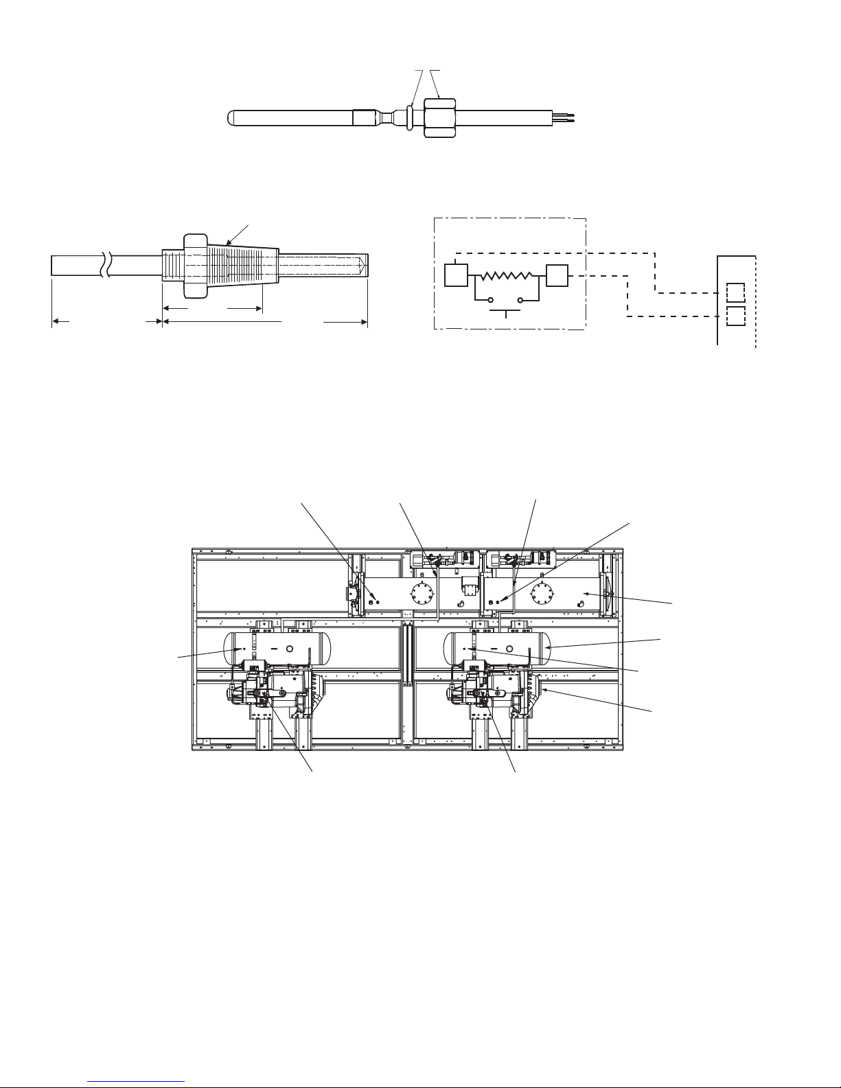
O-RING
BRASS NUT 3/8 - 24 FOR
ASSEMBLY ON BRASS WELL
6" MINIMUM
CLEARANCE FOR
THERMISTOR
REMOVAL
1.188 in.
2.315 in.
1/4-18 NPT
Fig. 42 — 5K Thermistor (Sensor 00PPG000008105A, Connector: HY06AM016)
Fig. 43 — Dual Leaving Water Thermistor Well
(00PPG000008000A)
Fig. 44 — Typical Remote Space Temperature
Sensor (33ZCT55SPT) Wiring
SENSOR
a30-4079
a30-4080
a30-4081
ECONOMIZER PRESSURE
TRANSDUCER (EPT A)
ECONOMIZER PRESSURE
TRANSDUCER (EPT B)
OIL PRESSURE TRANSDUCER
(OPT A)
OIL PRESSURE TRANSDUCER
(OPT B)
DISCHARGE PRESSURE
TRANSDUCER (DPT A)
DISCHARGE PRESSURE
TRANSDUCER (DPT B)
SUCTION PRESSURE
TRANSDUCER (SPT A)
SUCTION PRESSURE
TRANSDUCER (SPT B)
B
A
CIRCUIT A CIRCUIT B
COOLER
OIL SEPARATOR
COMPRESSOR
Fig. 45A — Transducer Locations (Flooded Cooler Units)
a30-4467
SEN
SEN
TB6
7
8
72
Page 73
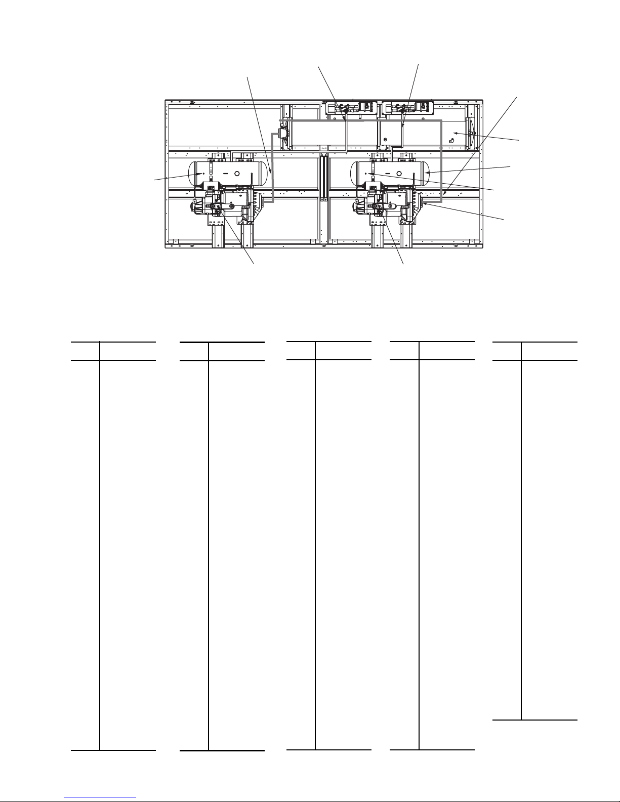
(
SUCTION PRESSURE
Fig. 45B — Transducer Locations (DX Cooler Units)
a30-5329
TEMP
(F)
RESISTANCE
(Ohms)
–25 98,010
–24 94,707
–23 91,522
–22 88,449
–21 85,486
–20 82,627
–19 79,871
–18 77,212
–17 74,648
–16 72,175
–15 69,790
–14 67,490
–13 65,272
–12 63,133
–11 61,070
–10 59,081
–9 57,162
–8 55,311
–7 53,526
–6 51,804
–5 50,143
–4 48,541
–3 46,996
–2 45,505
–1 44,066
0 42,679
1 41,339
2 40,047
3 38,800
4 37,596
5 36,435
6 35,313
7 34,231
8 33,185
9 32,176
10 31,202
11 30,260
12 29,351
13 28,473
14 27,624
15 26,804
16 26,011
17 25,245
18 24,505
19 23,789
20 23,096
21 22,427
22 21,779
23
21,153
24 20,547
25 19,960
TEMP
(F)
RESISTANCE
(Ohms)
77 4,976
78 4,855
79 4,737
80 4,622
81 4,511
82 4,403
83 4,298
84 4,196
85 4,096
86 4,000
87 3,906
88 3,814
89 3,726
90 3,640
91 3,556
92 3,474
93 3,395
94 3,318
95 3,243
96 3,170
97 3,099
98 3,031
99 2,964
100 2,898
101 2,835
102 2,773
103 2,713
104 2,655
105 2,597
106 2,542
107 2,488
108 2,436
109 2,385
110 2,335
111 2,286
112 2,239
113 2,192
114 2,147
115 2,103
116 2,060
117 2,018
118 1,977
119 1,937
120 1,898
121 1,860
122 1,822
123 1,786
124 1,750
125
1,715
126 1,680
127 1,647
TEMP
(F)
RESISTANCE
(Ohms)
179 570
180 561
181 551
182 542
183 533
184 524
185 516
186 508
187 501
188 494
189 487
190 480
191 473
192 467
193 461
194 456
195 450
196 445
197 439
198 434
199 429
200 424
201 419
202 415
203 410
204 405
205 401
206 396
207 391
208 386
209 382
210 377
211 372
212 367
213 361
214 356
215 350
216 344
217 338
218 332
219 325
220 318
221 311
222 304
223 297
224 289
225 282
TEMP
(F)
RESISTANCE
(Ohms)
26 19,393
27 18,843
28 18,311
29 17,796
30 17,297
31 16,814
32 16,346
33 15,892
34 15,453
35 15,027
36 14,614
37 14,214
38 13,826
39 13,449
40 13,084
41 12,730
42 12,387
43 12,053
44 11,730
45 11,416
46 11,112
47 10,816
48 10,529
49 10,250
50 9,979
51 9,717
52 9,461
53 9,213
54 8,973
55 8,739
56 8,511
57 8,291
58 8,076
59 7,686
60 7,665
61 7,468
62 7,277
63 7,091
64 6,911
65 6,735
66 6,564
67 6,399
68 6,238
69 6,081
70 5,929
71 5,781
72 5,637
73 5,497
74 5,361
75 5,229
76 5,101
TEMP
(F)
RESISTANCE
(Ohms)
128 1,614
129 1,582
130 1,550
131 1,519
132 1,489
133 1,459
134 1,430
135 1,401
136 1,373
137 1,345
138 1,318
139 1,291
140 1,265
141 1,240
142 1,214
143 1,190
144 1,165
145 1,141
146 1,118
147 1,095
148 1,072
149 1,050
150 1,029
151 1,007
152 986
153 965
154 945
155 925
156 906
157 887
158 868
159 850
160 832
161 815
162 798
163 782
164 765
165 750
166 734
167 719
168 705
169 690
170 677
171 663
172 650
173 638
174 626
175 614
176 602
177 591
178 581
TRANSDUCER (SPT A)
ECONOMIZER PRESSURE
TRANSDUCER (EPT A)
ECONOMIZER PRESSURE
TRANSDUCER (EPT B)
SUCTION PRESSURE
TRANSDUCER (SPT B)
COOLER
DISCHARGE PRESSURE
TRANSDUCER (DPT A)
OIL PRESSURE TRANSDUCER
OPT A)
Table 47A — 5K Thermistor Temperature (°F) vs Resistance
A
CIRCUIT A CIRCUIT B
OIL PRESSURE TRANSDUCER
(OPT B)
73
B
OIL SEPARATOR
DISCHARGE PRESSURE
TRANSDUCER (DPT B)
COMPRESSOR
Page 74
Table 47B — 5K Thermistor Temperature (°C) vs Resistance/Voltage
TEMP
(C)
RESISTANCE
(Ohms)
–32 100,260
–31 94,165
–30 88,480
–29 83,170
–28 78,125
–27 73,580
–26 69,250
–25 65,205
–24 61,420
–23 57,875
–22 54,555
–21 51,450
–20 48,536
–19 45,807
–18 43,247
–17 40,845
–16 38,592
–15 38,476
–14 34,489
–13 32,621
–12 30,866
–11 29,216
–10 27,633
–9 26,202
–8 24,827
–7 23,532
–6 22,313
–5 21,163
–4 20,079
–3 19,058
–2 18,094
–1 17,184
0 16,325
1 15,515
2 14,749
3 14,026
4 13,342
5 12,696
6 12,085
7 11,506
8 10,959
9 10,441
10 9,949
11 9,485
12 9,044
13 8,627
14 8,231
TEMP
(C)
RESISTANCE
(Ohms)
15 7,855
16 7,499
17 7,161
18 6,840
19 6,536
20 6,246
21 5,971
22 5,710
23 5,461
24 5,225
25 5,000
26 4,786
27 4,583
28 4,389
29 4,204
30 4,028
31 3,861
32 3,701
33 3,549
34 3,404
35 3,266
36 3,134
37 3,008
38 2,888
39 2,773
40 2,663
41 2,559
42 2,459
43 2,363
44 2,272
45 2,184
46 2,101
47 2,021
48 1,944
49 1,871
50 1,801
51 1,734
52 1,670
53 1,609
54 1,550
55 1,493
56 1,439
57 1,387
58 1,337
59 1,290
60 1,244
61 1,200
TEMP
(C)
RESISTANCE
(Ohms)
62 1,158
63 1,118
64 1,079
65 1,041
66 1,006
67 971
68 938
69 906
70 876
71 836
72 805
73 775
74 747
75 719
76 693
77 669
78 645
79 623
80 602
81 583
82 564
83 547
84 531
85 516
86 502
87 489
88 477
89 466
90 456
91 446
92 436
93 427
94 419
95 410
96 402
97 393
98 385
99 376
100 367
101 357
102 346
103 335
104 324
105 312
106 299
107 285
Economizer Assembly —
30XA090-500 units has an economizer assembly. The
30XA080,082 units do not have an economizer and have one
main electronic expansion valve. The 30XA080,082 units are
controlled the same way as units with a separate economizer
assembly. See Fig. 46.
Electronic Expansion Valve (EXV) — See Fig. 47
for a cutaway view of the EXV. High-pressure liquid refrigerant enters valve through the top. As refrigerant passes through
the orifice, pressure drops and refrigerant changes to a 2-phase
condition (liquid and vapor). The electronic expansion valve
operates through an electronically controlled activation of a
stepper motor. The stepper motor stays in position unless power pulses initiate the two discrete sets of motor stator windings
for rotation in either direction. The direction depends on the
phase relationship of the power pulses.
The motor directly operates the spindle, which has rotating
movements that are transformed into linear motion by the
transmission in the cage assembly. The valve cone is a V-port
type which includes a positive shut-off when closed.
The large number of steps and long stroke results in very accurate control of the refrigerant flow. The stepper motor has either 3690 (main) or 2785 (economizer) steps.
FLOODED COOLER MAIN EXV CONTROL — Each
circuit has a thermistor located in the discharge end of the compressor (DGT) and another one located in the compressor motor cavity (SGT). Each circuit also has discharge and suction
SERVICE
Each circuit on the
pressure transducer. Discharge and suction pressure as measured by the transducers are converted to saturated temperatures. The main control logic for the EXV uses discharge superheat to control the position of the EXV. The difference between the temperature of the discharge gas and the saturated
discharge temperature is the superheat. The EXV module controls the position of the electronic expansion valve stepper motor to maintain the discharge superheat set point.
The EXV control logic has several overrides, which are also
used to control the position of the EXV.
• Approach between SST (Saturated Suction Temperature)
and LWT
• Maximum Operating Pressure (MOP)
Approach
— If the approach (pinch), which is the difference
between leaving fluid temperature and saturated suction temperature, is equal to or less than the pinch set point then the
EXV will not open any further even though discharge superheat set point is not met. Pinch set point is calculated using
suction superheat, discharge superheat and pinch offset. Pinch
offset is used to adjust calculated pinch set point do to accuracy
of transducers and thermistors.
MOP
— The EXV is also used to limit cooler saturated suction
temperature to 62 F (16.6 C). This makes it possible for the
chiller to start at higher cooler fluid temperatures without overloading the compressor. This is commonly referred to as MOP
(maximum operating pressure). If the SST is equal to or greater
than the MOP set point then the MBB will try to control the
EXV position to maintain the MOP set point.
74
Page 75
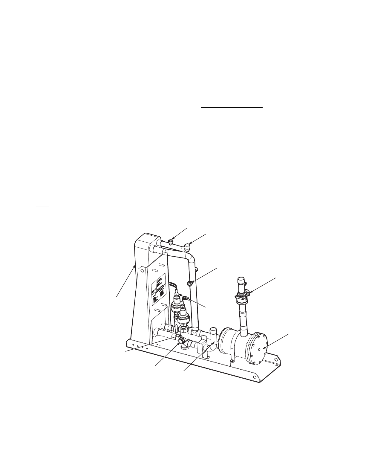
The discharge superheat leaving the compressor is main-
Fig. 46 — Economizer Assembly
a30-4468
tained between approximately 18° and 25° F (10° and 14° C),
or less. Because EXV status is communicated to the Main Base
Board (MBB) and is controlled by the EXV modules, it is possible to track the valve position. The unit is then protected
against loss of charge and a faulty valve. During initial start-up,
the EXV is fully closed. After an initialization period, valve
position is tracked by the EXV module by constantly monitoring the amount of valve movement.
DX (Direct Expansion) COOLER MAIN EXV CONTROL — Each circuit has a thermistor located in a well in the
discharge of the compressor (DGT) and another one located in
the compressor motor cavity (SGT). Thermistors are also located in a well in the water inlet and outlet nozzles. Apart from
thermistors, each circuit also has a discharge and suction pressure transducer. Discharge and suction pressures as measured
by the transducers are converted to saturated temperatures. The
main control logic for the EXV uses approach temperature in
the cooler (Water Inlet Temperature – Saturated Suction Temperature) and suction superheat (Suction Temperature – Saturated Suction Temperature) to control the position of the EXV.
The EXV module controls the position of the electronic expansion valve stepper motor to maintain a minimum approach and
a suction superheat set point.
The EXV control logic has several overrides, which are also
used to control the position of the EXV.
• Maximum Operating Pressure (MOP)
• High Discharge Gas Temperature
• Low Discharge Superheat
MOP
— The EXV is also used to limit cooler saturated suction
temperature to 62 F (16.6 C). This makes it possible for the
chiller to start at higher cooler fluid temperatures without overloading the compressor. This is commonly referred to as MOP
(maximum operating pressure). If the SST (Saturated Suction
Temperature) is equal to or greater than the MOP set point then
the MBB will try to control the EXV position to maintain the
MOP set point.
High Discharge Gas Temperature
— The EXV is also used to
limit the discharge gas temperature to 200 F (93.3 C). This
makes it possible for the chiller to operate at low load and high
ambient temperature without overloading the compressor. If
the DGT is approaching the High DGT limit then the control
will try to control the EXV position to bring the DGT down by
opening the EXV.
Low Discharge Superheat
— The EXV is also used to limit
the discharge superheat (DSH) to 18° F (10° C). This makes it
possible for the chiller to operate at high load and low ambient
temperature without overloading the compressor. If the DSH
goes below 18° F (10° C) the MBB will try to control the EXV
position to bring the discharge superheat up by closing the
EXV valve.
The suction superheat entering the compressor is maintained between approximately 15° and 25° F (8.3° and 14° C)
while maintaining a constant approach in the cooler. Because
EXV status is communicated to the Main Base Board (MBB)
and is controlled by the EXV modules, it is possible to track the
valve position. During initial start-up, the EXV is fully closed.
After an initialization period, valve position is tracked by the
EXV module by constantly monitoring the amount of valve
movement.
BRAZE PLATE
HEAT EXCHANGER
MAIN EXV
*SIGHT GLASS
*Economizer EXV has sight glass
on opposite side of valve shown.
MAIN FLOW
TO COOLER
ECONOMIZER
RELIEF
ECONOMIZER
FLOW TO
COMPRESSOR
ECONOMIZER
EXV
ECONOMIZER
RELIEF
LIQUID LINE
SHUT OFF
VALV E
FILTER DRIER
75
Page 76
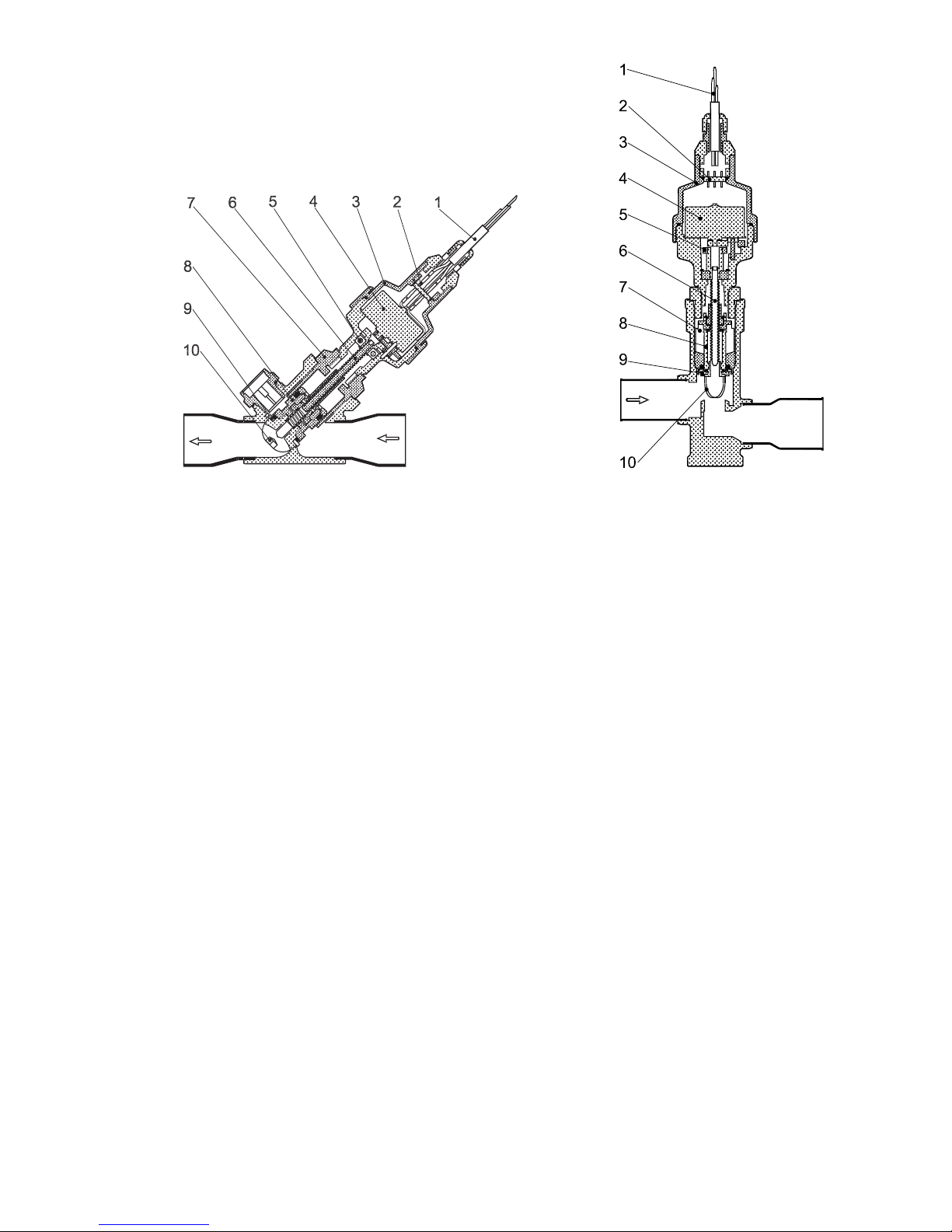
ECONOMIZER EXV CONTROL — The economizer EXV
Fig. 47 — Cutaway Views of the Electronic Expansion Valve
1. Cable
2. Glass Seal
3. Motor Housing
4. Stepper Motor
5. Bearing
6. Lead Screw
7. Insert
8. Valve Piston
9. Valve Seat
10. Valve Port
a30-4241
is controlled by the circuit EXV board. There is an economizer
gas temperature thermistor and economizer pressure transducer
located in the line, which runs from the economizer assembly to
the compressor. The economizer pressure is converted to saturated temperature and is used to calculate economizer superheat.
Economizer superheat equals economizer temperature minus
saturated economizer temperature. The economizer EXV only
operates during normal conditions when the capacity of the
circuit is greater than 75%. Once the capacity of the circuit is
greater than 75% the MBB will start controlling the economizer
EXV to maintain economizer superheat set point, which is approximately 8° to 12° F (4.4° to 6.7° C). If the circuit capacity is
less than 75%, the economizer EXV will be closed.
The economizer EXV has one override. If the discharge gas
temperature exceeds 195 F (90.6 C) the economizer EXV will
start to open. The EXV will be controlled to maintain discharge
gas temperature at approximately 195 F (90.6 C).
If it appears that main EXV or economizer EXV is not
properly controlling circuit operation to maintain correct superheat, there are a number of checks that can be made using test
functions and initialization features built into the microprocessor control. See the Service Test section to test EXVs.
EXV TROUBLESHOOTING PROCEDURE — There are
two different economizer EXVs. Both of the economizer
EXVs have a total of 2785 steps. There are three different main
EXVs, which all have a total of 3690 steps. The EXV motor
moves at 150 steps per second. Commanding the valve to
either 0% or 100% will add an additional 160 steps to the
move, to ensure the valve is open or closed completely.
Follow the steps below to diagnose and correct EXV
problems. Check EXV motor operation first. Switch the
Enable/Off/Remote (EOR) Contact switch to the Off position.
Check the appropriate circuit EXV, Circuit A EXV % Open
(Circuit A EXV Position, EXV.A), Circuit B EXV % Open
(Circuit B EXV Position, EXV.B), or Circuit C EXV % Open
(Circuit C EXV Position, EXV.C). The current value of 0 will
be displayed. Increase the EXV position to select 100% valve
position. The actuator should be felt moving through the EXV.
To close the valve, select 0%. The actuator should knock when
it reaches the bottom of its stroke. See Table 48 for a list of
EXV modes and submodes.
If the valve is not working properly, continue with the fol-
lowing test procedure:
Check the 8-position DIP switch on the board for the proper
address (see page 11). Check the EXV output signals at appropriate terminals on the EXV module. For 30XA080 units,
connect the positive test lead to EXV-J2A terminal 5 for Circuit
A and to EXV-J2B terminal 5 for Circuit B.
For 30XA090-500 units connect positive test lead to
EXV(X)-J2A terminal 5 for EXV(X) and EXV(X)-J2B terminal 5 for Economizer EXV(X). Using the Service Test procedure on page 105, move the valve output under test to 100%.
DO NOT short meter leads together or pin 5 to any other pin,
as board damage will occur. During the next several seconds,
carefully connect the negative test lead to pins 1,2,3 and 4 in
succession. Digital voltmeters will average this signal and
display approximately 6 vdc. If the output remains at a constant
voltage other than 6 vdc or shows 0 volts, remove the connector to the valve and recheck.
Select 0% to close the valve.
NOTE: Twelve vdc is the output from the EXV board when
the valve is stationary.
See Tables 6 and 7. If a problem still exists, replace the
EXV board. If the reading is correct, the expansion valve and
EXV wiring should be checked. Check the EXV connector and
interconnecting wiring.
1. Check color-coding and wire connections. Make sure
they are connected to the correct terminals at the EXV
board and EXV plug and that the cables are not crossed.
2. Check for continuity and tight connection at all pin
terminals.
Check the resistance of the EXV motor windings. For
30XA080,082 units remove the EXV module plug EXV-J2A
for Circuit A EXV and EXV-J2B for Circuit B EXV. For
30XA090-500 units remove the EXV module plug EXV(X)J2A for main EXV and EXV(X)-J2B for economizer EXV.
Check the resistance of the two windings between pins 1 and 3
for one winding and pins 2 and 4 for the other winding. The
resi
stance should be 52 ohms (± 5.2 ohms). Also check pins 1-4
for any shorts to ground.
76
Page 77
Table 48 — EXV Modes and Submodes
EXV TYPE AND CIRCUIT TOUCH PILOT™ PATH NAVIGATOR™ PATH
EXV, Circuit A Main Menu
EXV, Circuit B Main Menu
EXV, Circuit C Main Menu
Economizer EXV, Circuit A Main Menu
Economizer EXV, Circuit B Main Menu
Economizer EXV, Circuit C Main Menu
StatusCIRCA_AN Service Test ModeQUICEXV.A
StatusCIRCB_AN Service Test ModeQUICEXV.B
StatusCIRCC_AN Service Test ModeQUICEXV.C
StatusQCK_TST1 Service Test ModeQUICECO.A
StatusQCK_TST1 Service Test ModeQUICECO.B
StatusQCK_TST1 Service Test ModeQUICECO.C
Inspecting/Opening Electronic Expansion Valves
IMPORTANT: Obtain replacement gaskets before
opening EXV. Do not re-use gaskets.
To check the physical operation of an EXV, the following
steps must be performed if the unit does not have service valve
option or activated ball valves (ABV) (flooded coolers only)
the complete charge needs to be recovered using proper recovery techniques Steps 1-3 shown below. If the unit has ABV or
discharge service valves, only perform Steps 1 and 2.
1. Close the liquid line service valve of the circuit to be
checked. Put the Enable/Off/Remote Contact switch in
the Off position. Enter the Service Test mode and change
Service Test Enable, T.REQ from OFF to ON. A pass-
word may be required. Switch the EOR switch to the
Enable position. Under the COMP sub-mode, enable one
of the compressors (CP.xn) for the circuit. Let compres-
sor run until gage on suction pressure port reads 10 psig
(68.9 kPa). Turn the compressor off. The compressor will
turn off. Immediately after the compressor shuts off,
manually close the actuated ball valve (ABV) (see the
Actuated Ball Valve section for instructions). If the unit is
equipped with suction service valves, discharge service
valve, and economizer service valves, close all valves.
Closing the valves will minimize the amount of charge
that will have to be removed from the system after pump
down.
2. Remove any remaining refrigerant from the system low
side using proper recovering techniques. The economizer
assembly has a
1
/4-in. access connection which can be
used to remove charge from the inlet of the EXVs. Turn
off the line voltage power supply to the compressors.
CAUTION
Ensure refrigerant is removed from both the inlet and outlet
of EXV assemblies. Equipment damage could result.
3. The expansion valve motor is hermetically sealed inside
the top portion of the valve. See Fig. 47. Disconnect the
EXV plug. Carefully unscrew the motor portion from the
body of the valve. The EXV operator will come out with
the motor portion of the device. Reconnect the EXV plug.
4. Enter the appropriate EXV test step under the (QUIC)
Service Test mode Locate the desired item Circuit A
EXV Position, EXV.A, Circuit B EXV Position,
EXV.B, or Circuit C EXV Position, EXV.C. Change the
position to 100%. Observe the operation of the lead
screw. See Fig. 47. The motor should be turning, raising
the operator closer to the motor. Motor actuator movement should be smooth and uniform from fully closed to
fully open position. Select 0% and check open to closed
operation. If the valve is properly connected to the processor and receiving correct signals, yet does not operate
as described above, the sealed motor portion of the valve
should be replaced.
Installing EXV Motor
IMPORTANT: Obtain replacement gasket before
opening EXV. Do not re-use gaskets.
If re-installing the motor, be sure to use a new gasket in the
assembly. See Fig. 48. It is easier to install the motor assembly
with the piston in the fully closed position. Insert the motor into
the body of the EXV. Tighten the motor to the body to 36 ft-lb
(50 N-m) and then tighten the valve another 30 degrees.
Moisture Liquid Indicator — Clear flow of liquid refrigerant
indicates sufficient charge in system. Bubbles in the sight glass
indicate undercharged system or presence of noncondensables.
Moisture in system, measured in parts per million (ppm),
changes color of indicator. See Table 49. Change filter drier at
first sign of moisture in system.
Table 49 — Color Indicators when
Moisture is Present in Refrigerant
COLOR
INDICATOR
Green — Dry <30 <45
Yellow-green — Caution 30-100 45-170
Yellow — Wet >100 >170
R-134A,
75 F (24 C)
(ppm)
R-134A,
125 F (52 C)
(ppm)
IMPORTANT: Unit must be in operation at least
12 hours before moisture indicator can give an accu-
rate reading.
With unit running, indicating element must be in con-
tact with liquid refrigerant to give true reading.
Filter Drier — Whenever moisture-liquid indicator shows
presence of moisture, replace filter drier(s). There is one filter
drier assembly on each circuit with either one or two cores.
The 30XA080-122 units have one core per circuit. The
30XA140-162 units have two cores, in circuit A and one for
circuit B. The 30XA180-500 units have two cores per circuit.
Refer to the Carrier Standard Service Techniques Manual,
Chapter 1, Refrigerants, for details on servicing filter driers.
Liquid Line Service Valve — This valve is located immediately
ahead of filter drier, and has a
1
/4-in. access connection for field
charging. In combination with compressor discharge service
valve, each circuit can be pumped down into the high side for
servicing.
Compressor Assembly — The 30XA units utilize
screw compressors with a modulating slide valve which varies
capacity from 30% to 100% of compressor capacity for each
circuit. See Fig. 49 for a view of a typical 06T compressor.
The slide valve position is varied by opening and closing the
2 solenoid valves located on the compressor. To unload the
compressor, both solenoids are deenergized. To increase in
capacity both solenoid valves are energized together which
will cause the slide valve to slide towards the fully loaded
position. To stop the loading process solenoid 2 is energized
and solenoid 1 is deenergized. This will cause the slide valve to
maintain its current position. There is no feedback for the position of the slide valve. The control utilizes compressor current
77
Page 78
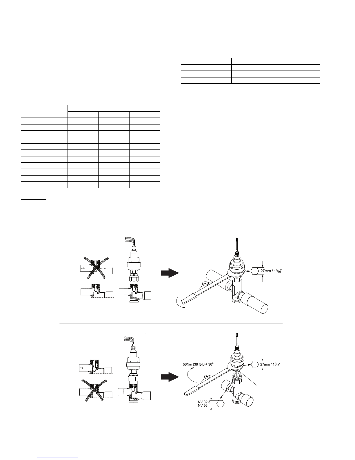
as an indicator of the slide valve position. Once the calculated
Closed
Open
Closed
Open
EF05BD271
EF05BD331
mm
mm
GASKET
OPEN VALVE IN QUICK TEST SUB-MODE BEFORE DISASSEMBLING
DISASSEMBLY
ASSEMBLY
NOTES:
1. Push down on valve piston to close valve before assembling.
2. After valve is assembled close valve in Quick Test sub-mode or cycle power before opening service valve.
Fig. 48 — Disassembly and Assembly of EXV Motor
NOTE: Open valve in Quick Test sub-mode before disassembling.
a30-4072
position of the slide valve reaches 100% circuit capacity, the
control will try to increase capacity again if the compressor
current continues to increase. The control will continue to load
the compressor until the compressor current no longer
increases. At that time the control will energize both solenoids
and the circuit will be considered fully loaded.
COMPRESSOR OIL SYSTEM — Each compressor/circuit
has its own oil system which includes an oil filter, oil solenoid,
check valve, oil level switch, oil separator heater, oil pressure
transducer, and an oil shut-off valve. A typical oil system is
shown in Fig. 50. See Table 50.
Table 50 — Unit Oil Quantities
30XA UNIT SIZE
080-122 5.5 [20.8] 5.5 [20.8] —
140-162 6.25 [23.7] 5.5 [20.8] —
180-202 6.25 [23.7] 6.25 [23.7] —
220,222 6.75 [25.6] 6.25 [23.7] —
240,242 6.75 [25.6] 6.75 [25.6] —
260,262 7.50 [28.4] 6.75 [25.6] —
280-302 7.50 [28.4] 6.75 [25.6] —
325-352 7.50 [28.4] 7.50 [28.4] —
400 6.75 [25.6] 6.75 [25.6] 7.50 [28.4]
450 7.50 [28.4] 6.25 [23.7] 7.50 [28.4]
500 7.50 [28.4] 6.75 [25.6] 7.50 [28.4]
Oil Charge
— When additional oil or a complete charge is
OIL CHANGE (gal, [liters])
Circuit A Circuit B Circuit C
required it must meet the following specifications:
• Manufacturer . . . . . . . . . . . . . . . . . . . . . Emkarate RL220XL
• Oil Type. . . . . . . . . . . . . . . . . . . Inhibited polyolester-based
synthetic compressor lubricant for use with screw compressors.
• ISO Viscosity Grade . . . . . . . . . . . . . . . . . . . . . . . . . . . . . 220
Do not reuse drained oil or any oil that has been exposed to the
atmosphere.
Oil is available in the following quantities from your local
Carrier representative:
QUANTITY TOTALINE PART NO.
1 Quart P903-2325
1 Gallon P903-2301
5 Gallon P903-2305
If unsure if there is low oil charge in the system, follow the
steps below:
1. If the unit shuts off repeatedly from a low oil level alert it
may be an indication of inadequate oil charge; however, it
could also indicate that the oil is not being reclaimed from
the low-side of the system.
2. Begin running the unit at full load for 1
1
/2 hours. Use the
manual Test Mode feature of Service Test if the unit does
not normally run at full load.
NOTE: An adequate load must be available.
3. After running the unit for 1
1
/2 hours at full load, allow the
unit to restart and run normally. If low oil alarms persist,
continue with the following steps.
4. Close the liquid line service valve and place a pressure
gage on top of the cooler or suction line service port. Enable the Service Test feature and turn the Enable/Off/Remote switch to the enable position. Start the desired circuit by turning it on under the TEST function: CP.A for
compressor A, CP.B for compressor B, or CP.C for com-
pressor C.
78
Page 79
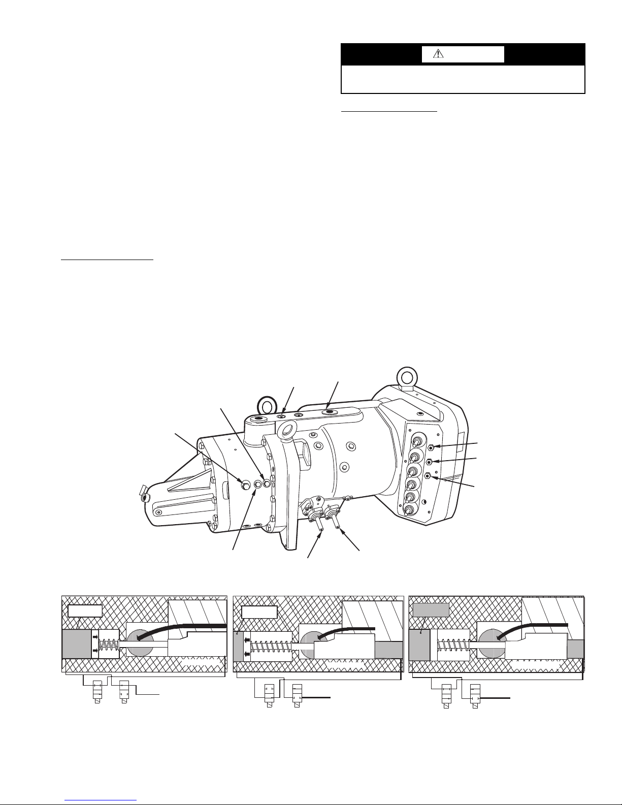
5. When the compressor starts successfully, observe the
SOLENOID 1
SOLENOID 2
HIGH PRESSURE
SWITCH
MOTOR TEMPERATURE
SENSOR 2
COMMON
MOTOR TEMPERATURE
SENSOR 1
text
Compre ssion
Process
High Pressure Oil
De-energized
FLOW
Valve #2 (NO)
De-energized
NO FLOW
Valve #1 (NC)
Bleed Line to Low Pres sure Suction
l
Discharge
Port
Unloader Piston
Chamber
text
Compression
Process
Loaded Position
High Pressure Oil
Energized
NO FLOW
Valve #2 (NO)
Energized
FLOW
Valve #1 (NC)
Bleed Line to Low Pressure Suction
Slide Valve
Discharge
Port
Unlo ader Piston
Chamber
Loaded Position
High with
High
Pressure
Oil
Drain to
Low Pressure
Unloaded Position
Slide Valve
text
High Pressur e Oil
Trapped
Oil at
High
Pressure
Compression
Process
Part Load Position
Energized
NO FLOW
Valve #2 (NO)
De-energized
NO FLOW
Valve #1 (NC)
Bleed Line to Low Pressure Suction
Slide Valve
Discharge
Port
Unloader Piston
Chamber
Slide Valve
FULLY LOADED OPERATION FULLY UNLOADED OPERATION
MAINTAIN POSITION
OIL PRESSURE
TRANSDUCER
LOCATION
DISCHARGE
GAS THERMISTOR
ACCESS
FITTING
SUCTION
TEMPERATURE
Fig. 49 — Typical 06T Compressor (All Units)
a30-4469
cooler pressure. When the pressure reads 10 psig
(68.9 kPa), turn the Emergency Switch (SW2) to the OFF
position. The compressor should stop.
6. Open the liquid line service valve and allow the unit to
restart normally. If low oil level alarms persist, continue
with the following steps.
7. If none of the previous steps were successful, the unit is
low on oil charge. Add oil to the oil separator using the
1
/4 in. access fitting that the discharge pressure transducer
is mounted to.
NOTE: To facilitate the oil charging process, ensure that
the unit is not running when adding oil. The system is under pressure even when the unit is not running, so it is
necessary to use a suitable pump to add oil to the system.
Using a suitable pump, add
tem. Continue adding oil in
1
/2 gal (1.9 l) of oil to the sys-
1
/2 gal (1.9 l) increments until
the problem is resolved, up to a maximum of 1.5 gal
(5.7 l). If it is necessary to add factory oil charge levels to
the system contact your local Carrier representative.
Oil Filter Maintenance
— Each circuit has one oil filter located externally to the compressor. Oil line pressure drop is
monitored by the control. Oil line pressure drop is calculated
by subtracting oil pressure (OP) from discharge pressure (DP).
If the oil line pressure drop exceeds 30 psi (206.8 kPa) for
5 minutes the control will generate a High Oil Filter Pressure
Drop alert. The High Oil Filter Pressure Drop alert will
not shut down the compressor, but instead indicates that the
oil filter is dirty. If oil pressure line losses exceed 50 psi
(344.7 kPa) then the control will shut down the circuit on
Maximum Oil Filter Differential Pressure Failure.
CAUTION
Compressor oil is pressurized. Use proper safety precautions when relieving pressure.
Replacing the Oil Filter
ed in front of the oil filter. Connect a charging hose to the
— Close the oil line ball valve locat-
1
/4-in.
access fitting port located downstream of the valve and bleed
off oil trapped between the service valve and the oil solenoid
valve. A quart of oil is typically what is removed during this
process. Remove the charging hose. Unscrew the nuts from
both ends of the oil filter and remove the oil filter. Remove the
protective caps from the new oil filter and install, being careful
not to lose or damage the new O-ring located on the new oil filter. Draw a vacuum at the Schrader port. Remove the charging
hose and open the oil line ball valve. Check both fittings for
leaks.
Flooded Cooler Units
FLOODED COOLER UNIT SUCTION SERVICE
VALVE — The suction service valve is a factory-installed option for 30XA units. It is located in the suction outlet of the
cooler. The suction service valve is bolted between the cooler
outlet and the suction flange piping. The suction service valve
shaft has a locking device located on the shaft to lock the valve
in either a fully open position or a fully closed position. The
locking device must be pulled out prior to moving the valve
handle to a fully open or a fully closed position. See Fig. 51A
and 51B.
79
Page 80
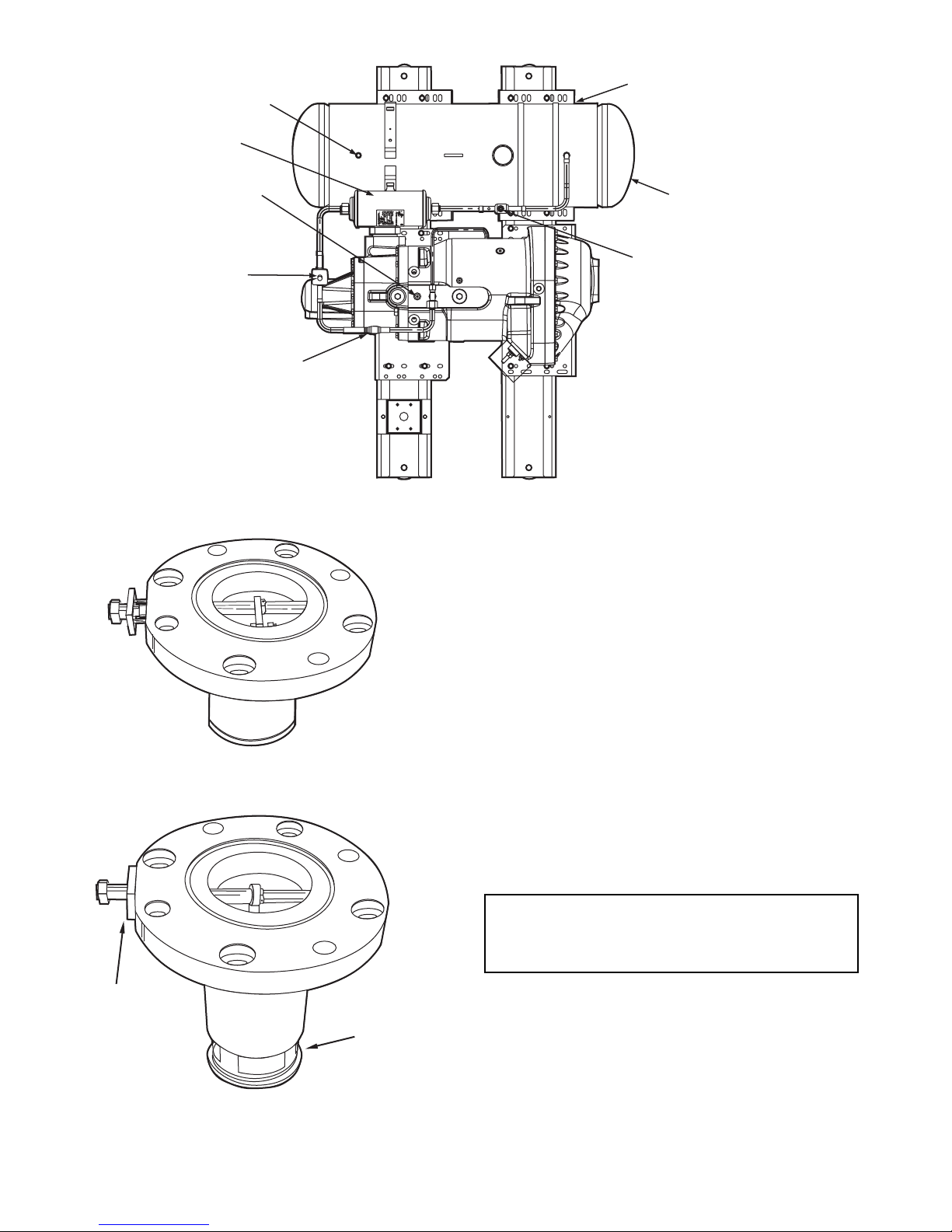
OIL SHUT OFF
VALV E
OIL LEVEL
SWITCH
(BOTTOM)
CHECK
VALV E
OIL
SOLENOID
VALV E
OIL
PRESSURE
TRANSDUCER
OIL
FILTER
OIL
SEPARATOR
HEATER
(BOTTOM)
HIGH
PRESSURE
TRANSDUCER
Fig. 50 — Typical Oil System (All Units)
a30-4243
Fig. 51B — Suction Service Valve Locking Device,
Open and Locked (Flooded Cooler Units)
a30-5246
a30-5247
Fig. 51A — Suction Service Valve Locking Device,
Closed and Unlocked (Flooded Cooler Units)
VALV E
LOCKED
OPEN
FLOODED COOLER FREEZE PROTECTION — All
coolers are equipped with cooler heaters and are controlled by
the Main Base Board. The control logic uses the unit status,
outdoor air temperature, and the saturated suction temperatures
for all circuits to decide if the cooler heater should be energized. The cooler heaters can only be energized when the state
of the unit is OFF. The cooler heaters will be energized if the
outdoor-air temperature is less than the Cooler Heater Set Point
and the lowest circuit Saturated Suction Temperature is less
than the heater set point plus 6° F (3.3° C). See Table 51. The
cooler heater set point = freeze point + Cooler Heater DT Setp
(Cooler Heater Delta Spt, HTR). If the entering or leaving
water temperature is less than the Heater Set Point and the outdoor air temperature is less than the Heater Set Point –2° F
(1.1° C), then the heater will be turned on.
If the Entering or Leaving Water Temperature is less than
the Brine Freeze Setpoint (Brine Freeze Setpoint, LOSP)
+1.0° F (0.5° C), then the heater will be turned on along with
the pump.
The entire cooler is covered with closed-cell insulation
applied over the heater. The heater plus insulation protects
cooler against low ambient temperature freeze-up to 0° F
(–17.8 C).
IMPORTANT: If unit is installed in an area where
ambient temperatures fall below 32 F (0° C), a suitable
corrosion-inhibited antifreeze solution or cooler heater
must be used in the chilled water circuit.
FLOODED COOLER LOW FLUID TEMPERATURE —
Main Base Board is programmed to shut chiller down if leaving fluid temperature drops below 34 F (1.1 C) for cooler fluid
type water or below Brine Freeze Setpoint (Brine Freeze Set-
point, LOSP) for cooler fluid type brine. The unit will shut
down without a pumpout. When fluid temperature rises to
6° F (3.3° C) above the leaving fluid set point, safety resets and
chiller restarts. Reset is automatic as long as this is the first
occurrence.
80
Page 81
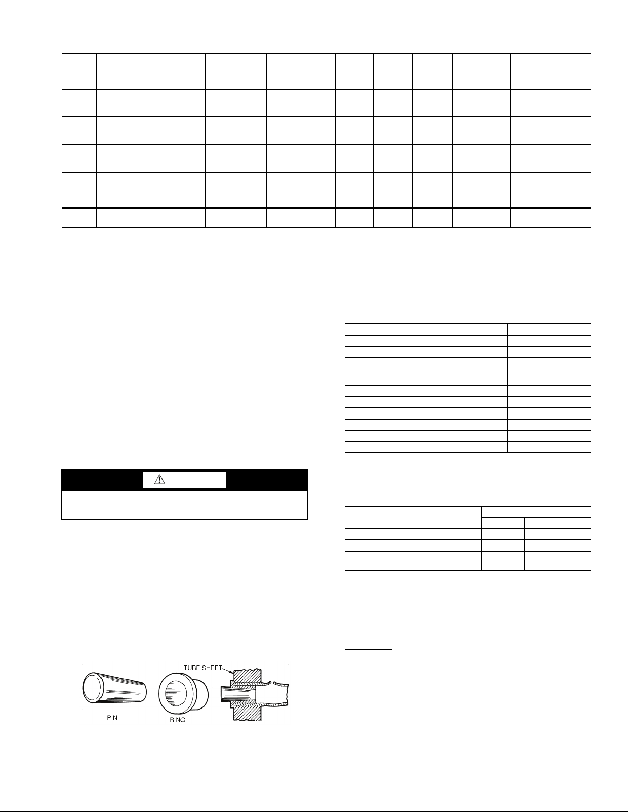
Table 51 — Cooler Heater Operation Examples for Flooded Coolers
Fig. 52 — Elliott Tube Plug
a30-4083
OAT
F (C)
50
(10)
40
(4.4)
40
(4.4)
40
(4.4)
40
(4.4)
LEGEND
N/A — Not Applicable
OAT — Outdoor-Air Temperature
SSTA — Saturated Suction Temperature, Circuit A
SSTB — Saturated Suction Temperature, Circuit B
SSTC — Saturated Suction Temperature, Circuit C
UNIT
STATUS
OFF
OFF
OFF
OFF
ON
BRINE
FREEZE
POINT
F (C)
36
(2.2)
36
(2.2)
15
(–9.4)
36
(2.2)
36
(2.2)
COOLER
DELTA T
F (C)
6
(3.3)
6
(3.3)
6
(3.3)
6
(3.3)
6
(3.3)
COOLER
HEATER
SETPOINT
F (C)
42
(5.6)
42
(5.6)
21
(–6.1)
42
(5.6)
42
(5.6)
FLOODED COOLER LOSS OF FLUID FLOW PROTECTION — All 30XA ma-chines include an integral flow switch
that protects the cooler against loss of cooler flow.
FLOODED COOLER TUBE PLUGGING — A leaky tube
can be plugged until retubing can be done. The number of
tubes plugged determines how soon the cooler must be
retubed. All tubes in the cooler may be removed. Loss of unit
capacity and efficiency as well as increased pump power will
result from plugging tubes. Failed tubes should be replaced as
soon as possible. Up to 10% of the total number of tubes can
be plugged before retubing is necessary. Figure 52 shows an
Elliott tube plug and a cross-sectional view of a plug in place.
See Tables 52 and 53 for plug components. If the tube failure
occurs in both circuits using tube plugs will not correct the
problem. Contact your local Carrier representative for assistance.
CAUTION
Use extreme care when installing plugs to prevent damage
to the tube sheet section between the holes.
FLOODED COOLER RETUBING — When retubing is required, obtain service of qualified personnel experienced in
boiler maintenance and repair. Most standard procedures can
be followed when retubing the coolers. An 8% crush is recommended when rolling replacement tubes into the tubesheet.
Place one drop of Loctite No. 675 or equivalent on top of
tube prior to rolling. This material is intended to “wick” into
the area of the tube that is not rolled into the tube sheet, and
prevent fluid from accumulating between the tube and the tube
sheet. New tubes must also be rolled into the center tubesheet
to prevent circuit to circuit leaks.
SSTA
F (C)
N/A N/A N/A OFF
41
(5)
41
(5)
52.1
(11.2)
N/A N/A N/A OFF
SSTB
F (C)
N/A N/A ON
N/A N/A OFF
52.1
(11.2)
SSTC
F (C)
52.1
(11.2)
COOLER
HEATER
STATUS
OFF
COMMENTS
OAT
>42 F
(5.6 C)
SSTA
<42 F
(5.6 C)
SSTA
>21 F
(–6.1 C)
All SST
Temperatures
>52 F
(11.2 C)
Unit Status
ON
Table 52 — Plug Component Parts
(Flooded Cooler Units Only)
COMPONENT PART NUMBER
For Tubes
Brass Pin 853103-1*
Brass Ring
For Holes without tubes
Brass Pin 853103-1A
Brass Ring 85102-738
Loctite No. 675 †
Locquic “N”†
Roller Extension S82-112/11
*Order directly from Elliot Tube Company, Dayton, OH or RCD.
†Can be obtained locally.
853002-640 or 657*
(measure tube
before ordering)
Table 53 — Flooded Cooler Tube Components
COMPONENT
Tube sheet hole diameter 0.756 19.20
Tube O D 0.750 19.05
Tube ID after rolling (includes
expansion due to clearance.)
NOTE: Tubes replaced along heat exchanger head partitions must
be flush with tube sheet (both ends).
0.650 to
0.667
SIZE
in. mm
16.51 to 16.94
FLOODED COOLER TIGHTENING COOLER HEAD
BOLTS
Preparation
— When reassembling cooler heads, always
check the condition of the O-rings first. The O-ring should be
replaced if there is visible signs of deterioration, cuts or
damage. Apply a thin film of grease to the O-ring before
installation. This will aid in holding the O-ring in the groove
while the head is installed. Torque all bolts to the following
specification and in sequence:
3
/4-in. Diameter Perimeter Bolts (Grade 5) . . . 200 to 225 ft-lb
(271 to 305 N-m)
81
Page 82
1. Install all bolts finger tight.
9
5
2
4
7
11
12
8
1
3
6
10
13
14
15
16
SINGLE
PAS S
ONLY
Fig. 53 — Flooded Cooler Unit Head
Recommended Bolt Torque Sequence
a30-4246
2. Bolt tightening sequence is outlined in Fig. 53. Follow
the numbering or lettering sequence so that pressure is
evenly applied to O-ring.
3. Apply torque in one-third steps until required torque is
reached. Load all bolts to each one-third step before proceeding to next one-third step.
4. No less than one hour later, retighten all bolts to required
torque values.
5. After refrigerant is restored to system, check for refrigerant leaks using recommended industry practices.
6. Replace cooler insulation.
FLOODED COOLER INSPECTING/CLEANING HEAT
EXCHANGERS — Inspect and clean cooler tubes at the end
of the first operating season. Because these tubes have internal
ridges, a rotary-type tube cleaning system is necessary to fully
clean the tubes. Tube condition in the cooler will determine the
scheduled frequency for cleaning, and will indicate whether
water treatment is adequate in the chilled water/brine circuit.
Inspect the entering and leaving water thermistor wells for
signs of corrosion or scale. Replace the well if corroded or remove any scale if found.
located in the suction line for each circuit. The suction service
valve is either a ball valve type valve or a butterfly type valve.
DX COOLER FREEZE PROTECTION — Coolers can be
ordered with heaters installed in the factory. If equipped, the
main base board based on the outdoor-air temperature and the
entering and leaving water thermistors controls the cooler heaters. The Heater Set Point is the sum of the freeze point and
Cooler Heater DT Setp (Configuration
SERVHTR).
If the entering or leaving water temperature is less than the
Heater Set Point and the outdoor air temperature is less than
the Heater Set Point – 2° F (1.1° C), then the heater will be
turned on.
If the Entering or Leaving Water Temperature is less than
the Brine Freeze Setpoint (Configuration
SERVLOSP) +
1.0° F (0.5° C), then the heater will be turned on along with the
pump.
Entire cooler is covered with closed-cell insulation applied
over the heater. Heater plus insulation protect cooler against
low ambient temperature freeze-up to –20 F (–28 C).
IMPORTANT: If unit is installed in an area where
ambient temperatures fall below 32 F (0° C), it is recommended that a suitable corrosion-inhibited antifreeze solution be used in chilled water circuit.
DX COOLER LIQUID FLUID TEMPERATURE — Main
Base Board is programmed to shut chiller down if leaving fluid
temperature drops below 34 F (1.1 C) for cooler fluid type water or below Brine Freeze Setpoint (Brine Freeze Setpoint,
LOSP) for cooler fluid type brine. The unit will shut down
without a pumpout. When fluid temperature rises to 6 F (3.3 C)
above the leaving fluid set point, safety resets and chiller restarts. Reset to automatic as long as this is the first occurance.
DX COOLER LOSS OF FLUID FLOW PROTECTION — All 30XA machines include an integral flow switch
that protects the cooler against loss of cooler flow.
DX COOLER TUBE PLUGGING — A leaky tube can be
plugged until retubing can be done. The number of tubes
plugged determines how soon the cooler must be retubed. If
several tubes require plugging, check with a local Carrier representative to find out how the number and location of tubes
can affect unit capacity. Fig. 54 shows an Elliott tube plug and
a cross-sectional view of a plug in place. See Tables 54 and 55
for plug components.
CAUTION
Hard scale may require chemical treatment for its prevention or removal. Consult a water treatment specialist for
proper treatment procedures.
FLOODED COOLER WATER TREATMENT — Untreated or improperly treated water may result in corrosion, scaling,
erosion or algae. The services of a qualified water treatment
specialist should be obtained to develop and monitor a treatment program.
CAUTION
Water must be within design flow limits, clean and treated
to ensure proper machine performance and reduce the
potential of tubing damage due to corrosion, scaling, and
algae. Carrier assumes no responsibility for cooler damage
resulting from untreated or improperly treated water.
DX Cooler Units
DX COOLER SUCTION SERVICE VALVE — The suction
service valve is a factory-installed option for 30XA units. It is
CAUTION
Use extreme care when installing plugs to prevent damage
to the tube sheet section between the holes.
Table 54 — DX Cooler Unit Plug Component Part
Numbers
COMPONENTS FOR PLUGGING PART NUMBER
For Tubes
Brass Pin 853103-312*
Brass Ring 853002-322*
For Holes without tubes
Brass Pin 853103-375
Brass Ring 853002-377
Loctite No. 675 †
Locquic “N” †
*Order directly from Elliot Tube Company, Dayton, OH or RCD.
†Can be obtained locally.
82
Page 83
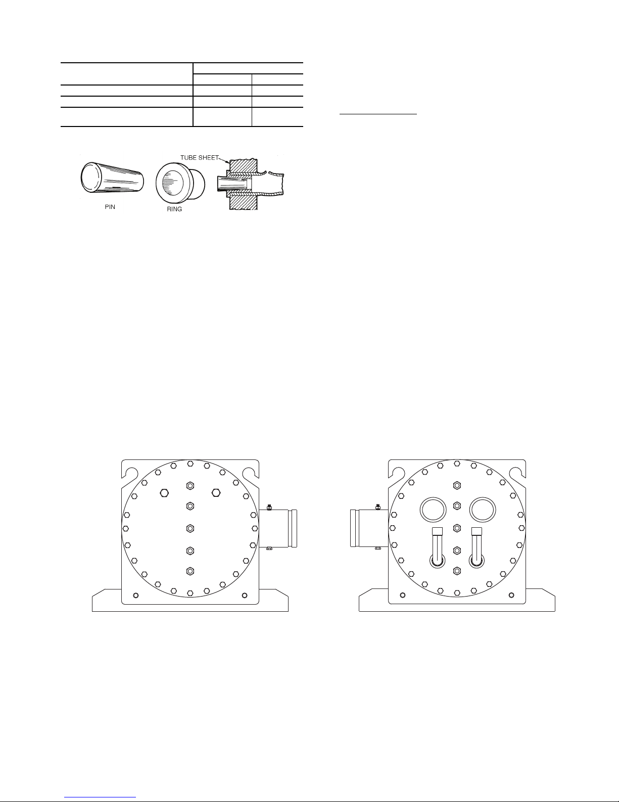
Table 55 — DX Cooler Unit Plug Component
Fig. 54 — Elliott Tube Plug
Fig. 55 — Bolt Tightening Sequence, 30XA082,092,102,122
a30-5330
Dimensions
PLUG COMPONENT
Tube sheet hole diameter 0.377-0.382 9.58-9.70
Tube O D 0.373-0.377 9.47-9.58
Tube ID after rolling (includes
expansion due to clearance.)
NOTE: Tubes next to gasket webs must be flush with tube sheet
(both ends).
SIZE
in. mm
0.328 8.33
For the 30XA142,162,182,202,222,242,262,282,302,327,
352 DX coolers, the pass partition has a perforated distribution
plate in the inlet pass to more uniformly distribute the refrigerant as it enters the tubes of the cooler. The perforated distribution plate is on the tubesheet side of the pass partition. A tube
plug will interfere with the installation of pass partition. The
tube plug must be flush with the tube sheet to prevent this interference. The pass partition is symmetrical, meaning the partition plate can be rotated 180 degrees, however, the performance
of the machine will be affected if the pass partition is installed
incorrectly.
DX COOLER RETUBING — When retubing is required,
obtain service of qualified personnel experienced in boiler
maintenance and repair. Most standard procedures can be followed when retubing the coolers. An 8% crush is recommended when rolling replacement tubes into the tubesheet.
The following Elliott Co. tube rolling tools are required:
• Expander Assembly
• Cage
• Mandrel
•Rolls
Place one drop of Loctite No. 675 or equivalent on top of
tube prior to rolling. This material is intended to “wick” into the
area of the tube that is not rolled into the tube sheet, and prevent
fluid from accumulating between the tube and the tube sheet.
DX COOLER TIGHTENING COOLER HEAD BOLTS
(Fig. 55-58)
Gasket Preparation
— When reassembling cooler heads, always use new gaskets. Gaskets are neoprene-based and are
brushed with a light film of compressor oil. Do not soak gasket
or gasket deterioration will result. Use new gaskets within
30 minutes to prevent deterioration. Reassemble cooler nozzle
end or plain end cover of the cooler with the gaskets. Torque all
cooler bolts to the following specification and sequence:
5
/8-in. Diameter Perimeter Bolts (Grade 5) . . . 150 to 170 ft-lb
(201 to 228 N-m)
1
/2-in. Diameter Flange Bolts (Grade 5) . . . . . . . . 70 to 90 ft-lb
(94 to 121 N-m)
1
/2-in. Diameter Center Stud (Grade 5). . . . . . . . . 70 to 90 ft-lb
(94 to 121 N-m)
1. Install all bolts finger tight, except for the suction flange
bolts. Installing these flanges will interfere with tightening the center stud nuts.
2. Bolt tightening sequence is outlined in Fig. 55-58. Follow
the numbering or lettering sequence so that pressure is
evenly applied to gasket.
3. Apply torque in one-third steps until required torque is
reached. Load all bolts to each one-third step before proceeding to next one-third step.
4. No less than one hour later, retighten all bolts to required
torque values.
5. After refrigerant is restored to system, check for refrigerant leaks using recommended industry practices.
6. Replace cooler insulation.
29
27
26
23
22
19
18
15
14
8
11
6
10
13
4
2
1
3
5
7
17
21
25
28
24
20
16
12
9
29
27
26
23
22
19
18
15
14
6
8
11
10
13
4
2
1
3
5
7
17
21
25
28
24
20
16
12
9
83
Page 84
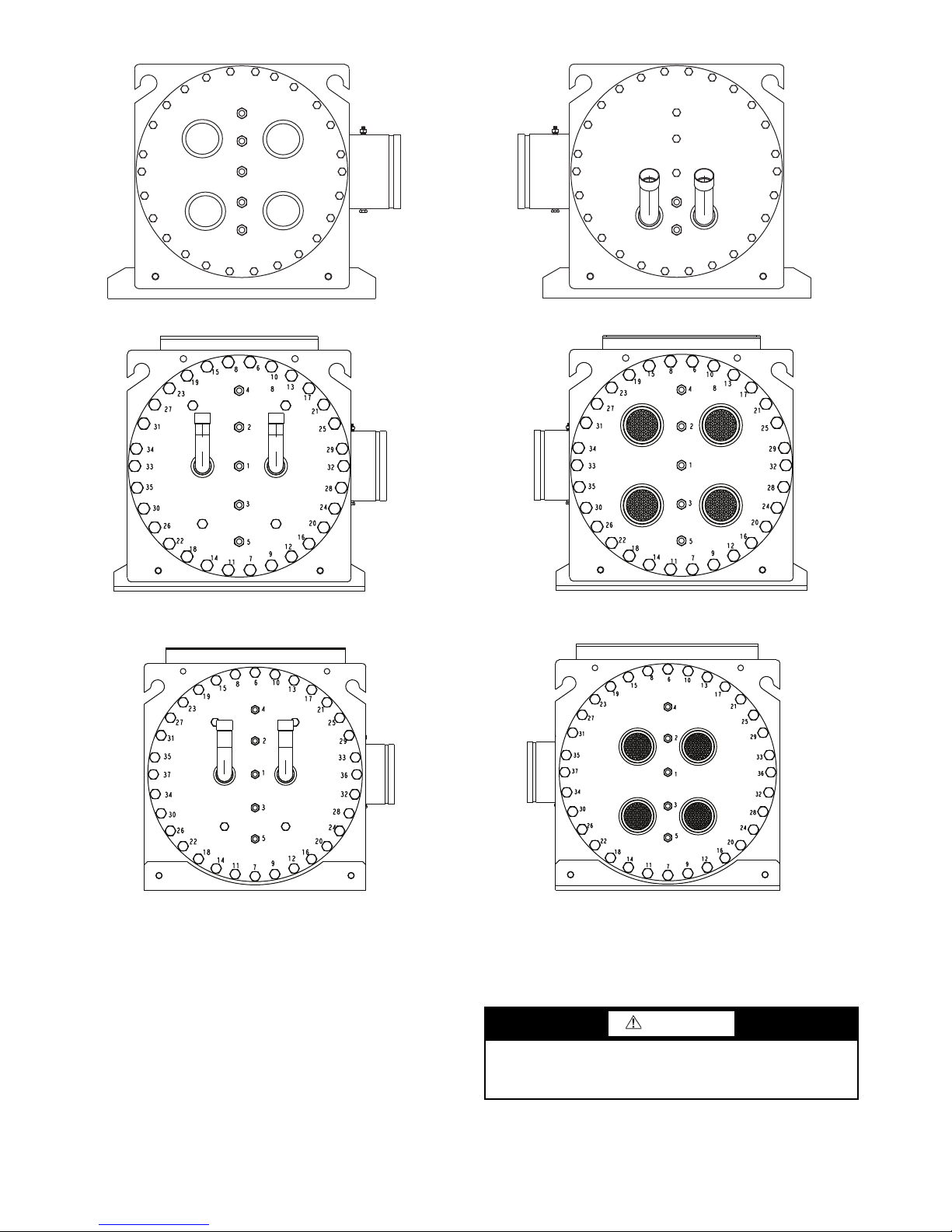
29
Fig. 56 — Bolt Tightening Sequence, 30XA142,162,182,202
a30-5331
Fig. 57 — Bolt Tightening Sequence, 30XA222, 242, 262, 282
a30-5407
Fig. 58 — Bolt Tightening Sequence, 30XA302, 327, 352
a30-5408
31
28
25
24
21
20
17
16
13
12
9
12
6
11
15
4
2
1
3
5
7
19
23
27
30
26
22
18
14
10
8
6
9
11
15
4
2
1
3
5
7
19
23
27
30
26
22
18
14
10
8
29
31
28
25
24
21
20
17
13
16
DX COOLER CHILLED WATER FLOW SWITCH — A
factory-installed flow switch is installed in the entering water
nozzle for all machines. See Fig. 59 and 60. This is a thermaldispersion flow switch. Figure 59 shows typical installation. If
nuisance trips of the sensor are occurring, follow the steps below to correct:
1. Check to confirm that all strainers are clean, valves are
open and pumps are running. For the case of variable
frequency drive (VFD) controlled pumps, ensure the
minimum speed setting has not been changed.
2. Measure the pressure drop across the cooler. Use the
cooler pressure drop curves on pages 62-67 to calculate
the flow and compare this to system requirements.
DX Cooler and Flooded Cooler Units
PREPARATION FOR WINTER SHUTDOWN — If the
unit is not operational during the winter months, at the end of
cooling season complete the following steps.
CAUTION
Failure to remove power before draining heater equipped
coolers and hydronic packages can result in heater tape and
insulation damage.
1. If the unit has optional heater tapes on the cooler and the
cooler will not be drained, do not shut off power disconnect during off-season shutdown. If the unit has optional
84
Page 85
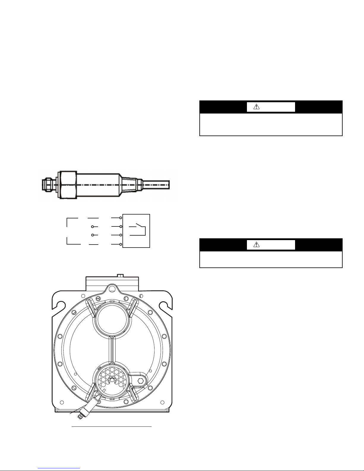
heater tapes on the cooler and the cooler is drained, open
STANDARD FLOODED COOLER
OUT
IN
FLOW SWITCH
Fig. 59 — Chilled Water Flow Switch
Fig. 60 — Flow Switch
a30-5335
a30-5334
the circuit breaker for the heater, CB-13 or shut off power
during off-season shutdown.
2. Draining the fluid from the system is highly recommended. If the unit is equipped with a hydronic package, there
are additional drains in the pump housing and strainer
that must be opened to allow for all for all of the water to
drain.
3. Isolate the cooler from the rest of the system with water
shutoff valves.
4. Replace the drain plug and completely fill the cooler with
a mixture of water and a suitable corrosion-inhibited antifreeze solution such as propylene glycol. The concentration should be adequate to provide freeze protection to
15° F (8.3° C) below the expected low ambient temperature conditions. Antifreeze can be added through the vent
on top of the cooler. If the unit has a hydronic pump package, the pump must be treated in the same manner.
5. Leave the cooler filled with the antifreeze solution for the
winter, or drain if desired. Be sure to deenergize heaters
(if installed) as explained in Step 1 to prevent damage.
Use an approved method of disposal when removing antifreeze solution.
24 VAC
L1
N
BRN
WHT
BLK
BLU
1
2
4
3
At the beginning of the next cooling season, be sure that
there is refrigerant pressure on each circuit before refilling
cooler, add recommended inhibitor, and reset the CB-HT (circuit breaker heater) (if opened) or restore power.
Microchannel Heat Exchanger (MCHX) Condenser Coil Maintenance and Cleaning Recommendations — Routine cleaning of coil surfaces is
essential to maintain proper operation of the unit. Elimination
of contamination and removal of harmful residues will greatly
increase the life of the coil and extend the life of the unit. The
following steps should be taken to clean MCHX condenser
coils:
CAUTION
Do not apply any chemical cleaners to MCHX condenser
coils. These cleaners can accelerate corrosion and damage
the coil.
1. Remove any foreign objects or debris attached to the coil
face or trapped within the mounting frame and brackets.
2. Put on personal protective equipment including safety
glasses and/or face shield, waterproof clothing and
gloves. It is recommended to use full coverage clothing.
3. Start high pressure water sprayer and purge any soap or
industrial cleaners from sprayer before cleaning condenser coils. Only clean potable water is authorized for cleaning condenser coils.
4. Clean condenser face by spraying the coil steady and uniformly from top to bottom while directing the spray
straight toward the coil. Do not exceed 900 psig
(6205 kPa) or 30 degree angle. The nozzle must be at
least 12 in. (304.8 mm) from the coil face. Reduce pressure and use caution to prevent damage to air centers.
CAUTION
Excessive water pressure will fracture the braze between
air centers and refrigerant tubes.
RTPF (Round Tube Plate Fin) Condenser Coil
Maintenance and Cleaning Recommendations —
maintain proper operation of the unit. Elimination of contamination and removal of harmful residues will greatly increase
the life of the coil and extend the life of the unit. The following
maintenance and cleaning procedures are recommended as part
of the routine maintenance activities to extend the life of the
coil.
REMOVE SURFACE LOADED FIBERS — Surface loaded fibers or dirt should be removed with a vacuum cleaner. If a
vacuum cleaner is not available, a soft non-metallic bristle
brush may be used. In either case, the tool should be applied in
the direction of the fins. Coil surfaces can be easily damaged
(fin edges can be easily bent over and damage to the coating of
a protected coil) if the tool is applied across the fins.
NOTE: Use of a water stream, such as a garden hose, against a
surface loaded coil will drive the fibers and dirt into the coil.
This will make cleaning efforts more difficult. Surface loaded
fibers must be completely removed prior to using low velocity
clean water rinse.
PERIODIC CLEAN WATER RINSE — A periodic clean
water rinse is very beneficial for coils that are applied in coastal
or industrial environments. However, it is very important that
the water rinse is made with very low velocity water stream to
avoid damaging the fin edges. Monthly cleaning as described
below is recommended.
Routine cleaning of coil surfaces is essential to
85
Page 86
ROUTINE CLEANING FOR RTPF COIL SURFACE —
Monthly cleaning with Totaline
®
environmentally sound coil
cleaner is essential to extend the life of coils. This cleaner is
available from Carrier Replacement Parts division as part number P902-0301 for a one gallon container, and part number
P902-0305 for a five gallon container. It is recommended that
all coils, including the standard copper tube aluminum fin, precoated fin, copper fin, or e-coated coils be cleaned with the
Totaline environmentally sound coil cleaner as described
below. Coil cleaning should be part of the unit’s regularly
scheduled maintenance procedures to ensure long life of the
coil. Failure to clean the coils may result in reduced durability
in the environment. Avoid the use of:
• coil brighteners
• acid cleaning prior to painting
• high pressure washers
• poor quality water for cleaning
Totaline environmentally sound coil cleaner is non-flammable, hypoallergenic, nonbacterial, and a USDA accepted biodegradable agent that will not harm the coil or surrounding components such as electrical wiring, painted metal surfaces, or insulation. Use of non-recommended coil cleaners is stongly
discouraged since coil and unit durability could be affected.
Totaline Environmentally Sound Coil Cleaner Application
Equipment
•21/2 gallon garden sprayer
• Water rinse with low velocity spray nozzle
CAUTION
Harsh chemicals, household bleach or acid or basic cleaners should not be used to clean outdoor or indoor coils of
any kind. These cleaners can be very difficult to rinse out
of the coil and can accelerate corrosion at the fin/tube interface where dissimilar materials are in contact. If there is
dirt below the surface of the coil, use the Totaline environmentally sound coil cleaner as described above.
CAUTION
High velocity water from a pressure washer, garden hose,
or compressed air should never be used to clean a coil. The
force of the water or air jet will bend the fin edges and
increase airside pressure drop. Reduced unit performance
or nuisance unit shutdown may occur.
Totaline Environmentally Sound Coil Cleaner Application
Instructions
1. Proper eye protection such as safety glasses is recommended during mixing and application.
2. Remove all surface loaded fibers and dirt with a vacuum
cleaner as described above.
3. Thoroughly wet finned surfaces with clean water and a
low velocity garden hose, being careful not to bend fins.
4. Mix Totaline environmentally sound coil cleaner in a
1
2
/2 gallon garden sprayer according to the instructions
included with the cleaner. The optimum solution temperature is 100 F.
NOTE: Do NOT
enzymatic activity will be destroyed.
5. Thoroughly apply Totaline environmentally sound coil
cleaner solution to all coil surfaces including finned area,
tube sheets and coil headers.
6. Hold garden sprayer nozzle close to finned areas and
apply cleaner with a vertical, up-and-down motion. Avoid
spraying in horizontal pattern to minimize potential for
fin damage.
USE water in excess of 130 F (54.4 C), as the
7. Ensure cleaner thoroughly penetrates deep into finned
areas.
8. Interior and exterior finned areas must be thoroughly
cleaned.
9. Finned surfaces should remain wet with cleaning solution
for 10 minutes.
10. Ensure surfaces are not allowed to dry before rinsing.
Reapplying cleaner as needed to ensure 10-minute
saturation is achieved.
11. Thoroughly rinse all surfaces with low velocity clean
water using downward rinsing motion of water spray
nozzle. Protect fins from damage from the spray nozzle.
Condenser Fans — A formed metal mount bolted to fan
deck supports each fan and motor assembly. A shroud and a
wire guard provide protection from the rotating fan. See
Fig. 61. The exposed end of the fan motor shaft is protected
from weather by grease. If fan motor must be removed for
service or replacement, be sure to regrease fan shaft and
reinstall fan guard. The fan motor has a step in the motor shaft.
For proper performance, fan should be positioned such that it is
securely seated on this step. Tighten the bolt to 15 ft lb ± 2.0
(20.34 Nm ± 2.7 Nm) .
Refrigerant Circuit
LEAK TESTING — Units are shipped with complete operating charge of refrigerant R-134a (see Physical Data tables
supplied in the 30XA installation instructions) and should be
under sufficient pressure to conduct a leak test. If there is no
pressure in the system, introduce enough nitrogen to search for
the leak. Repair the leak using good refrigeration practices.
After leaks are repaired, system must be evacuated and
dehydrated.
REFRIGERANT CHARGE — Refer to Physical Data tables
supplied in the 30XA installation instructions). Immediately
ahead of filter drier in each circuit is a factory-installed liquid
line service valve. Each valve has a
for charging liquid refrigerant.
Charging with Unit Off and Evacuated
service valve before charging. Weigh in charge shown on unit
nameplate. Open liquid line service valve; start unit and allow
it to run several minutes fully loaded. Check for a clear sight
glass. Be sure clear condition is liquid and not vapor.
Charging with Unit Running
— If charge is to be added while
unit is operating, all condenser fans and compressors must be
operating. It may be necessary to block condenser coils at low
ambient temperatures to raise condensing pressure to approximately 198 psig (1365 kPa) to turn all condenser fans on. Do not
totally block a coil to do this. Partially block all coils in uniform
pattern. Charge each circuit until sight glass shows clear liquid,
and has a liquid line temperature of 103 F (39 C) for 30XA080352 units and 108 F (42 C) for 30XA400-500 units.
Add 3 to 5 lb (1.36 to 2.27 kg) depending on unit size of liquid charge into the fitting located on the tube entering the cooler. This fitting is located between the electronic expansion
valve (EXV) and the cooler.
Allow the system to stabilize and then recheck the liquid
temperature. If needed, add additional liquid charge, 3 to 5 lb
at a time, allowing the system to stabilize between each charge
addition. Slowly add charge as the sight glass begins to clear to
avoid overcharging.
IMPORTANT: When adjusting refrigerant charge, circulate fluid through cooler continuously to prevent freezing
and possible damage to the cooler. Do not overcharge, and
never charge liquid into the low-pressure side of system.
1
/4-in. access connection
— Close liquid line
86
Page 87
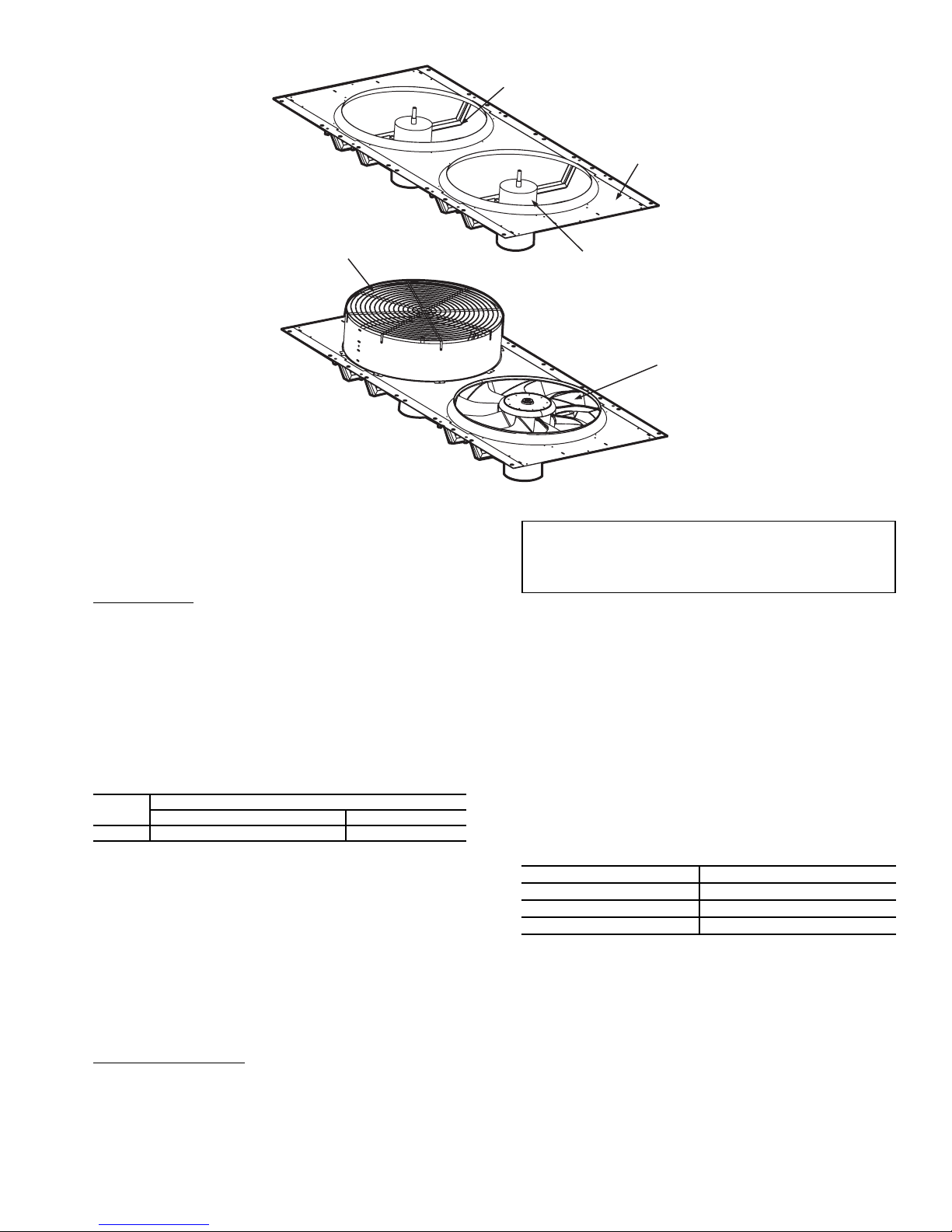
WIRE GUARD
FAN BLADE
FAN DECK
FORMED METAL
MOUNT
MOTOR
Fig. 61 — Fan Mounting
a30-4249
Safety Devices — The 30XA chillers contain many
safety devices and protection logic built into the electronic
control. Following is a description of the major safeties.
COMPRESSOR PROTECTION
Motor Overload
(CPM) protect each compressor against overcurrent. Do not
bypass the current transformers or make any changes to the
factory-installed and configured headers. The configuration of
these headers defines the Must Trip Amps (MTA) at which the
CPM will turn the compressors off. Determine the cause for
trouble and correct the problem before resetting the CPM. See
Appendix D for MTA settings and configuration headers.
Each CPM board also reads the status of each compressor’s
high-pressure switch. All compressors have factory-installed
high-pressure switches. See Table 56.
Table 56 — High-Pressure Switch Settings
UNIT
30XA 304.5 +7.25, –14.5 2099 +50, –100
If the switch opens during operation, the compressor will be
shut down. The CPM will reset automatically when the switch
closes, however, a manual reset of the control is required to
restart the compressor.
OIL SEPARATOR HEATERS — Each oil separator circuit
has a heater mounted on the underside of the vessel. The heater
is deenergized anytime the compressor is on. If the compressor
is off and outdoor-air temperature (OAT) is greater than 100 F
(37.8 C) the heater is deenergized. The heater will also be
deenergized if OAT – SST >32 F (17.8° C) and the OAT –
LWT > 32 F (17.8° C).
COOLER PROTECTION
Low Water Temperature
to shut the chiller down if the leaving fluid temperature drops
below 34 F (1.1 C) for water or more than 8 F (4.4 C) below
set point for Fluid Type = brine. When the fluid temperature
rises 6 F (3.3 C) above the leaving fluid set point, the safety
resets and the chiller restarts. Reset is automatic as long as this
is the first occurrence of the day.
— The compressor protection modules
SWITCH SETTING
psig kPa
— Microprocessor is programmed
IMPORTANT: If unit is installed in an area where
ambient temperatures fall below 32 F (0° C), a suitable corrosion-inhibited antifreeze solution or cooler
heater must be used in the chilled water circuit.
Relief Devices — Fusible plugs are located in each cir-
cuit between the condenser and the liquid line shutoff valve.
PRESSURE RELIEF VALVES — Valves are installed in each
circuit and are located on the coolers and oil separators. These
valves are designed to relieve if an abnormal pressure condition
arises. Relief valves on all coolers relieve at 220 psi (1517 kPa).
Relief valves on oil separators relieve at 350 psi (2413 kPa).
These valves should not be capped. If a valve relieves, it should
be replaced. If the valve is not replaced, it may relieve at a lower
pressure, or leak due to trapped dirt from the system which may
prevent resealing.
See Table 57. Some local building codes require that relieved gases be exhausted to a specific location. This connection allows conformance to this requirement.
Table 57 — Relief Valve Connection Specs
LOCATION CONNECTION SIZES
Oil Separator 3/8 SAE Flare
DX Cooler Option 5/8 SAE Flare
Flooded Cooler Option 3/4 in. NPT Female
MAINTENANCE
Recommended Maintenance Schedule —
lowing are only recommended guidelines. Jobsite conditions
may dictate that maintenance schedule is performed more often
than recommended.
Routine:
For machines with e-coat condenser coils:
• Check condenser coils for debris; clean as necessary with
Carrier approved coil cleaner.
• Periodic clean water rinse, especially in coastal and indus-
trial applications.
The fol-
87
Page 88
Every month:
Alarm Descriptor
th
Alarm Suffix
Code Number to identify source
.01
Alarm Prefix
A1 – Compressor A1 Failure
B1 – Compressor B1 Failure
C1 – Compressor C1 Failure
Co – Communication Failure
FC – Factory Configuration Error
MC – Master Chiller Configuration Error
P – Process Failure
Pr – Pressure Transducer Failure
Sr – Service Notification
th – Thermistor Failure
Alarm
Fig. 62 — Alarm Description
a30-4250
• Check condenser coils for debris; clean as necessary with
Carrier approved coil cleaner.
• Check moisture indicating sight glass for possible refrigerant loss and presence of moisture.
Every 3 months (for all machines):
• Check refrigerant charge.
• Check all refrigerant joints and valves for refrigerant leaks;
repair as necessary.
• Check chilled water flow switch operation.
• Check all condenser fans for proper operation.
• Check oil filter pressure drop.
• Check oil separator heater operation.
• Inspect pump seal, if equipped with a hydronic pump package.
Every 12 months (for all machines):
• Check all electrical connections; tighten as necessary.
• Inspect all contactors and relays; replace as necessary.
• Check accuracy of thermistors; replace if greater than ±2° F
(1.2° C) variance from calibrated thermometer.
• Check accuracy of transducers; replace if greater than ±5 psi
(34.47 kPa) variance.
• Check to be sure that the proper concentration of antifreeze
is present in the chilled water loop, if applicable.
• Verify that the chilled water loop is properly treated.
• Check refrigerant filter driers for excessive pressure drop;
replace as necessary.
• Check chilled water strainers, clean as necessary.
• Check cooler heater operation.
• Check condition of condenser fan blades and that they are
securely fastened to the motor shaft.
• Perform Service Test to confirm operation of all components.
• Check for excessive cooler approach (Leaving Chilled
Water Temperature – Saturated Suction Temperature) which
may indicate fouling. Clean cooler vessel if necessary.
• Obtain oil analysis; change as necessary.
TROUBLESHOOTING
See Table 58 for an abbreviated list of symptoms, possible
causes and possible remedies.
Alarms and Alerts — The integral control system con-
stantly monitors the unit and generates warnings when abnormal or fault conditions occur. Alarms may cause either a circuit
(Alert) or the whole machine (Alarm) to shut down. Alarms
and Alerts are assigned codes as described in Table 59. The
alarm/alert indicator LED on the Navigator™ module is illuminated when any alarm or alert condition is present. If an
Alert is active, the Alarm Indicator LED will blink. If an Alarm
is active, the Alarm Indicator LED will remain on. Currently
active Alerts and Alarms can be found in (Current Alarm,
ALRM).
The controller generates two types of alarms. Automatic
reset alarms will reset without any intervention if the condition
that caused the alarm corrects itself. Manual reset alarms
require the service technician to check for the alarm cause and
reset the alarm. The following method must be followed to
reset manual alarms:
Before resetting any alarm, first determine the cause of the
alarm and correct it. To reset the alarm, set R.ALM to YES.
The alarms will be reset. Indicator light will be turned off when
switched correctly. Do not reset the chiller at random without
first investigating and correcting the cause(s) of the failure.
Each alarm is described by a three or four-digit code. The
first one or two digits indicate the alarm source and are listed in
Fig. 62. The last two digits pinpoint the problem. See Table 59.
DIAGNOSTIC ALARM CODES AND POSSIBLE
CAUSES
Thermistor Failure
Alarm 1 — Cooler Fluid Entering (th.01)
Alarm 2 — Cooler Fluid Leaving (th.02)
Criteria for Trip — This alarm criterion is tested whether the
unit is on or off if the temperature as measured by the thermistor is outside of the range –40 to 245 F (–40 to 118.3 C).
Action to be Taken — The unit shuts down normally, or is not
allowed to start.
Reset Method — Automatic, the alarm will reset once the
thermistor reading is within the expected range.
Possible Causes — If this condition is encountered, check the
following items:
• sensor wiring to the Main Base Board
• sensor accuracy
See the Thermistors section on page 71 for thermistor description, identifiers and connections.
Defrost Thermistor Failure
Alarm 3 — Circuit A (th.03)
Alarm 4 — Circuit B (th.04)
NOTE: These alarms are not used or supported. If this condition is encountered, confirm machine configuration.
88
Page 89
Table 58 — Troubleshooting
SYMPTOM POSSIBLE CAUSE POSSIBLE REMEDY
Unit Does Not Run Check for power to unit • Check overcurrent protection device.
• Check non-fused disconnect (if equipped).
• Restore power to unit.
Wrong or incorrect unit
Check unit configuration.
configuration
Active alarm Check Alarm status. See the Alarms and Alerts section
and follow
troubleshooting instructions.
Active operating mode Check for Operating Modes. See the Operating Modes
section and follow troubleshooting instructions
Unit Operates too
Long or
Continuously
Low refrigerant charge Check for leak and add refrigerant.
Compressor or control
Replace contactor or relay.
contacts welded
Air in chilled water loop Purge water loop.
Non-condensables in
Remove refrigerant and recharge.
refrigerant circuit.
Inoperative EXV • Check EXV, clean or replace.
• Check EXV cable, replace if necessary.
• Check EXV board for output signal.
Load too high Unit may be undersized for application
Circuit Does Not Run Active alarm Check Alarm status. See the Alarms and Alerts section
and follow troubleshooting instructions.
Active operating mode Check for Operating Modes. See the Operating Modes
section and follow troubleshooting instructions.
Circuit Does Not
Load
Active alarm Check Alarm status. See the Alarms and Alerts section
and follow troubleshooting instructions.
Active operating mode Check for Operating Modes. See the Operating Modes
section and follow troubleshooting instructions.
Low saturated suction
See Operating Modes 21, 22 and 23.
temperature
High circuit suction superheat The circuit capacity is not allowed increase if circuit super-
heat is greater than 36°F (20 C). See Alarms 59-61 for
potential causes.
Low suction superheat The circuit capacity is not allowed to increase if the circuit
superheat is less than 18° F (10° C). See Alarms 62-64 for
potential causes.
Compressor Does
Not Run
Active alarm Check Alarm status. See the Alarms and Alerts section
and follow troubleshooting instructions.
Active operating mode Check for Operating Modes. See the Operating Modes
section and follow troubleshooting instructions.
Inoperative compressor
contactor
• Check control wiring.
• Check scroll protection module.
• Check contactor operation, replace if necessary.
Chilled Water Pump
is ON, but the
Cooler freeze protection Chilled water loop temperature too low. Check cooler
heater.
Machine is OFF
LEGEND
EXV — Electronic Expansion Valve
89
Page 90
Table 59 — Alarm Codes
PREFIX
CODE
CCN — Carrier Comfort Network® HPS — High Pressure Switch
CPM — Compressor Protection Module LW T — Leaving Water Temperature
DX — Direct Expansion MOP — Maximum Operating Pressure
EMM — Energy Management Module MTA — Must Trip Amps
EWT — Entering Water Temperature OAT — Outdoor Air Temperature
EXV — Electronic Expansion Valve SST — Saturated Suction Temperature
HGBP — Hot Gas Bypass UL — Underwriters Laboratories
SUFFIX
CODE
th 01 1 Cooler Entering Fluid
02 2 Cooler Leaving Fluid
03 3 Circuit A Defrost Thermistor Temperature measured
04 4 Circuit B Defrost Thermistor
06 5 Condenser Entering
07 6 Condenser Leaving
08 7 Reclaim Condenser
09 8 Reclaim Condenser
10 9 OAT Thermistor Temperature measured
11 10 Master/Slave Common Fluid
12 11 Circuit A Suction Gas
13 12 Circuit B Suction Gas
14 13 Circuit C Suction Gas
15 14 Circuit A Discharge Gas
16 15 Circuit B Discharge Gas
17 16 Circuit C Discharge Gas
18 17 Circuit A Condenser Sub-
19 18 Circuit B Condenser Sub-
21 19 Space Temperature
23 20 Cooler heater feedback
24 21 Circuit A Economizer Gas
25 22 Circuit B Economizer Gas
26 23 Circuit C Economizer Gas
Pr 01 24 Circuit A Discharge
02 25 Circuit B Discharge
03 26 Circuit C Discharge
04 27 Circuit A Suction Transducer
05 28 Circuit B Suction Transducer
06 29 Circuit C Suction Transducer
07 30 Circuit A Reclaim Pump-
08 31 Circuit B Reclaim Pump-
ALARM
NUMBER
ALARM DESCRIPTION REASON FOR ALARM
Thermistor
Thermistor
Fluid Thermistor
Fluid Thermistor
Entering Thermistor
Leaving Thermistor
Thermistor
Thermistor
Thermistor
Thermistor
Thermistor
Thermistor
Thermistor
cooling Liquid Thermistor
cooling Liquid Thermistor
Thermistor
thermistor
Thermistor
Thermistor
Thermistor
Transducer
Transducer
Transducer
down Pressure Transducer
down Pressure Transducer
LEGEND
Temperature measured
by the controller is
outside of the range
of –40 F to 245 F
(–40 C to 118 C)
by the controller is
outside of the range
of –40 F to 245 F
(–40 C to 118 C)
by the controller is
outside of the range
of –40 F to 245 F
(–40 C to 118 C)
Temperature measured
by the controller is
outside of the range
of –40 F to 245 F
(–40 C to 118 C)
Temperature measured
by the controller is
outside of the range
of –40 F to 245 F
(–40 C to 118 C)
Temperature measured
by the controller is
outside of the range
of –40 F to 245 F
(–40 C to 118 C)
Temperature measured
by the controller is
outside of the range
of –40 F to 245 F
(–40 C to 118 C)
Temperature measured
by the controller is
outside of the range
of –40 F to 245 F
(–40 C to 118 C)
Temperature measured
by the controller is
outside of the range
of –40 F to 245 F
(–40 C to 118 C)
Measured voltage is
0 vdc or SST > EWT and
EXV < 50% for 1 minute
Measured voltage is
0 vdc or SST > EWT and
EXV < 50% for 1 minute
ACTION TAKEN
BY CONTROL
Unit be shut down or
not allowed to start
None
Unit be shut down or
not allowed to start
Dual chiller deacti-
vated. Master and
slave machines
operate in stand-
alone mode
Circuit shut down or
not allowed to start
None
Alarm tripped
None
Circuit economizer
function disabled
Circuit shut down or
not allowed to start
None
RESET
TYPE
Automatic Faulty Sensor,
Automatic
Automatic
Automatic
Automatic
Automatic
Automatic
Automatic
Automatic Faulty transducer,
Automatic
PROBABLE CAUSE
wiring error or failed
main base board
Configuration error
Faulty Sensor,
wiring error or failed
main base board
Faulty Sensor,
wiring error, failed
EXV or CPM board
Configuration error
Faulty Sensor, wiring
error, failed EMM
board
Configuration error
Faulty Sensor,
wiring error, failed
EXV board
wiring error, failed
main base board or
fan board
Configuration error
90
Page 91
Table 59 — Alarm Codes (cont)
PREFIX
CODE
Co A1 38 Loss of communication with
CCN — Carrier Comfort Network® HPS — High Pressure Switch
CPM — Compressor Protection Module LW T — Leaving Water Temperature
DX — Direct Expansion MOP — Maximum Operating Pressure
EMM — Energy Management Module MTA — Must Trip Amps
EWT — Entering Water Temperature OAT — Outdoor Air Temperature
EXV — Electronic Expansion Valve SST — Saturated Suction Temperature
HGBP — Hot Gas Bypass UL — Underwriters Laboratories
SUFFIX
CODE
Pr 10 32 Circuit A Oil Pressure
P 01 52 Cooler Freeze Protection Entering or leaving therm-
ALARM
NUMBER
11 33 Circuit B Oil Pressure
12 34 Circuit C Oil Pressure
13 35 Circuit A Economizer
14 36 Circuit B Economizer
15 37 Circuit C Economizer
B1 39 Loss of communication with
C1 40 Loss of communication with
E1 41 Loss of communication with
E2 42 Loss of communication with
E3 43 Loss of communication with
F1 44 Loss of communication with
F2 45 Loss of communication with
F3 46 Loss of communication with
01 47 Loss of communication with
02 48 Loss of communication with
03 49 Loss of communication with
04 50 Loss of communication with
05 51 Loss of communication with
02 53 Condenser Freeze Protection
03 54 Condenser Freeze Protection
04 55 Condenser Freeze Protection
ALARM DESCRIPTION REASON FOR ALARM
Transducer
Transducer
Transducer
Pressure Transducer
Pressure Transducer
Pressure Transducer
Compressor Board A
Compressor Board B
Compressor Board C
EXV Board A
EXV Board B
EXV Board C
Fan Board 1
Fan Board 2
Fan Board 3
Free Cooling Board 1
Free Cooling Board 2
Energy Management Board
Heat Reclaim Board
AUX Board 6
Circuit A
Circuit B
Circuit C
LEGEND
Measured voltage is
0 vdc or SST > EWT and
EXV < 50% for 1 minute
Measured voltage is
0 vdc
No communication
with CPM board
No communication with
EXV board
No communication with
fan board
No communication with
fan board
No communication with
fan board
No communication with
free cooling board
No communication with
EMM board
No communication
with Free Cooling Board
No communication
with HGBP/PUMP Board
istor sensed a tempera-
ture at or below freeze
point
— None Automatic Configuration error
ACTION TAKEN
BY CONTROL
Circuit shut down or
not allowed to start
Circuit shut down or
not allowed to start
Affected
compressor shut
down
Affected
compressor
shut down
Circuit A/B shut
down or not allowed
to start (080-120
ton), Circuit A shut
down or not allowed
to start
(130-500 ton)
Circuit B shut down
or not allowed to
start (130-500 ton)
Circuit C shut down
or not allowed to
start (400-500 ton)
None Automatic Configuration error
Disable or not allow
EMM functions
3 step and 4-20 mA
and space tempera-
ture reset, occu-
pancy override and
ice build)
None Automatic Configuration error
Unit shut down or
not allowed to start
Unit shut down or
not allowed to start
RESET
TYPE
Automatic
Automatic Faulty transducer,
Automatic Wrong CPM address,
Automatic Wrong EXV board
Automatic Wrong board address,
Automatic Wrong board address,
Automatic Wrong board address,
Automatic Wrong board
Automatic
Automatic, first
occurrence in
24 hours;
manual if
multiple alarms
within 24 hours
PROBABLE CAUSE
Faulty transducer,
wiring error, failed CPM
wiring error, failed CPM
wrong unit configura-
tion, wiring error, power
address, wrong unit
configuration, wiring
error, power loss,
failed EXV board
wrong unit configuration, wiring error, loss
of power, failed board
wrong unit configuration, wiring error, loss
of power, failed board
wrong unit configuration, wiring error, loss
of power, failed board
address, wrong unit
configuration, wiring
error, power loss to
module, failed module
address, wrong unit
configuration, wiring
error, power loss to
module, failed module
Faulty thermistor, faulty
wiring, low water flow,
low loop volume, fouled
cooler, or freeze
board
board
loss, failed
CPM board
Wrong board
conditions
91
Page 92
Table 59 — Alarm Codes (cont)
PREFIX
CODE
CCN — Carrier Comfort Network® HPS — High Pressure Switch
CPM — Compressor Protection Module LW T — Leaving Water Temperature
DX — Direct Expansion MOP — Maximum Operating Pressure
EMM — Energy Management Module MTA — Must Trip Amps
EWT — Entering Water Temperature OAT — Outdoor Air Temperature
EXV — Electronic Expansion Valve SST — Saturated Suction Temperature
HGBP — Hot Gas Bypass UL — Underwriters Laboratories
SUFFIX
CODE
P 05 56 Circuit A Low Suction
MC nn 81 Master chiller configura-
FC n0 82 No factory configuration No Configuration Unit not allowed to
P 31 84 Unit is in CCN emer-
ALARM
NUMBER
06 57 Circuit B Low Suction
07 58 Circuit C Low Suction
08 59 Circuit A High Suction
09 60 Circuit B High Suction
10 61 Circuit C High Suction
11 62 Circuit A Low Suction
12 63 Circuit B Low Suction
13 64 Circuit C Low Suction
14 65 Interlock Failure Lockout Switch Closed Unit shut down or
28 66 Electrical Box Thermo-
29 67 Loss of communication
30 68 Master/Slave communi-
67 69 Circuit A Low Oil
68 70 Circuit B Low Oil
69 71 Circuit C Low Oil
70 72 Circuit A Max Oil Filter
71 73 Circuit B Max Oil Filter
72 74 Circuit C Max Oil Filter
84 75 Circuit A High Oil Filter
85 76 Circuit B High Oil Filter
86 77 Circuit C High Oil Filter
75 78 Circuit A Low Oil Level Oil level switch open Circuit shut down
76 79 Circuit B Low Oil Level
77 80 Circuit C Low Oil Level
nn 83 Illegal factory configura-
32 85 Cooler pump #1 fault Pump interlock status does
33 86 Cooler pump #2 fault
15 87 Condenser Flow Switch
ALARM DESCRIPTION REASON FOR ALARM
Temperature
Temperature
Temperature
Superheat
Superheat
Superheat
Superheat
Superheat
Superheat
stat Failure/Reverse
Rotation
with System Manager
cation Failure
Pressure
Pressure
Pressure
Differential Pressure
Differential Pressure
Differential Pressure
Drop Pressure
Drop Pressure
Drop Pressure
tion error Number 01 to
nn
tion Number 01 to 04
gency stop
Failure
LEGEND
Low saturated suction tem-
peratures detected for a
period of time
EXV>98%,
suction superheat > 30 F
(–1 C), and SST<MOP for
more than 5 minutes
EXV<5% and either the suc-
tion superheat is less than
the set point by at least 5 F
(–15 C) or the suction tem-
perature is greater than
MOP set point for more than
Communication between the
5 minutes
External pump interlock
Loss of communication with
an external control device
master and slave machines
Oil pressure and suction
pressure differential is less
Difference between discharge pressure and oil
pressure is greater than
Difference between discharge pressure and oil
pressure is greater than
Wrong or incompatible con-
Wrong or incompatible con-
Emergency stop command
open
for more than
2 minutes
lost
than the set point
50 psi for more than
30 seconds
30 psi for more than
5 minutes
figuration data
figuration data
has been received
not match pump
status
— None Manual Configuration error
ACTI ON TAKEN
BY CONTROL
Circuit shut down Automatic, first
Circuit shut down Manual Faulty transducer, faulty wir-
Circuit shut down Manual Faulty transducer, faulty wir-
not allowed to
start
Unit shut down or
not allowed to
start
Unit change to
stand-alone
operation
Unit change to
stand-alone
operation
Circuit shut down Automatic, first
Circuit shut down Manual Plugged oil filter, closed oil
Alert generated Manual Plugged oil filter
or not allowed to
start
Unit not allowed to
start in Master-
slave control
start
Unit not allowed to
start
Unit shut down or
not allowed to
start
Unit shuts down, if
available, another
pump will start
RESET
TYPE
occurrence in 24
hours;
manual if
multiple alarms
within 24 hours
Automatic Lockout Switch Closed
Automatic External pump off. Faulty
Automatic Faulty communication wir-
Automatic Faulty communication wir-
occurrence in 24
hours;
manual if
multiple alarms
within 24 hours
Automatic, first
occurrence in 24
hours; manual if
multiple alarms
within 24 hours
Automatic Configuration error
Automatic Configuration error
Automatic Configuration error
Automatic Carrier Comfort
Manual Faulty contacts, wiring error
PROBABLE CAUSE
Faulty thermistor, faulty wir-
ing, low water flow, low loop
volume, fouled cooler, or
freeze conditions.
Closed suction valve, DX
ing, faulty thermistor, faulty
EXV, low refrigerant charge,
plugged or restricted liquid
ing, faulty thermistor, faulty
jumper wiring when channel
ing, no power supply to the
ing, no power or control
Plugged oil filter, faulty oil
transducer, oil check valve
stuck, plugged oil strainer
valve, bad oil solenoid, oil
check valve stuck, faulty oil
Low oil level, faulty switch,
Network
or low control voltage. Con-
units.
line
EXV, or incorrect
configuration
on EMM board
not used
external controller
power to the main base
board of either module
pressure transducer
wiring error, failed CPM
board
(see Table 61)
®
Emergency Stop
command received
figuration error.
92
Page 93
PREFIX
CODE
A1, B1, C1 01 111-01,
SUFFIX
CODE
P 34 88 Circuit A Reclaim Operation
Sr nn 110 Service maintenance alert
ALARM
NUMBER
35 89 Circuit B Reclaim Operation
37 90 Circuit A — Repeated high
38 91 Circuit B — Repeated high
39 92 Circuit C — Repeated high
40 93 Circuit A — Repeated low
41 94 Circuit B — Repeated low
42 95 Circuit C — Repeated low
43 96 Low entering water tempera-
73 97 Condenser pump #1 default — None Manual Configuration error
74 98 Condenser pump #2 default
78 99 Circuit A High Discharge
79 100 Circuit B High Discharge
80 101 Circuit C High Discharge
81 102 Circuit A Low Economizer
82 103 Circuit B Low Economizer
83 104 Circuit C Low Economizer
87 105 Circuit A Slide Valve Control
88 106 Circuit B Slide Valve Control
89 107 Circuit C Slide Valve Control
90 108 Cooler flow switch set point
91 109 Cooler flow switch failure Flow switch open Unit shut down Manual if unit
97 127 Water Exchanger Tempera-
112-01,
113-01
02 111-02,
112-02,
113-02
03 111-03,
112-03,
113-03
ALARM DESCRIPTION REASON FOR ALARM
Failure
Failure
discharge gas overrides
discharge gas overrides
discharge gas overrides
suction temp overrides
suction temp overrides
suction temp overrides
ture in heating
Temperature
Temperature
Temperature
Pressure
Pressure
Pressure
Unverifiable
Unverifiable
Unverifiable
configuration failure
ture Sensors Swapped
Number # nn
Compressor Motor temperature too high
Compressor Motor temperature out of range
Compressor High pressure
switch protection
LEGEND
Table 59 — Alarm Codes (cont)
ACTION TAKEN
BY CONTROL
— None Manual Configuration error
Multiple capacity over-
rides due to high
saturated discharge
temperature
Multiple capacity
overrides due to low saturated suction temperature
Not supported — — —
Discharge gas tempera-
ture is higher than 212 F
(100 C) for more than
90 seconds
The economizer pressure
is below the suction pres-
sure more than 14.5 psi
for more than 10 seconds
If 100% load current is
less than 1.1 times of 30%
load current, or for 1 min-
ute when active cooling
setpoint is greater than
32 F (0°C).
— None Manual Configuration error
Control detects EWT
below LWT for 1 minute
Field programmed
elapsed time has expired
for maintenance time
Compressor temperature
higher than 232 F (111 C)
for more than 90 seconds
Compressor temperature
reading out of the range of
–40 F to 245 F
(–40 C to 118 C)
HPS input on CPM board
open
Circuit shut down Automatic Condenser air
Circuit shut down Automatic Inaccurate
Circuit shut down Manual Faulty transducer/high
Circuit shut down Manual Faulty transducer,
Unit shut down Manual Wiring error, EWT and
Circuit shut down Manual Motor cooling solenoid
Circuit shut down Manual Faulty thermistor, faulty
Circuit shut down Manual, press
RESET
TYPE
None Manual Slide valve stuck, inac-
is running,
automatic
otherwise
None Manual Maintenance required
reset button on
HPS
PROBABLE CAUSE
recirculation, dirty or
plugged condenser
coils, inaccurate
discharge transducer,
faulty condenser fan
transducer, faulty EXV,
low refrigerant charge,
plugged or restricted
liquid line filter drier.
pressure switch, low/
restricted condenser
flow
faulty main base board,
faulty wiring, closed
suction service valve,
faulty EXV
curate initial current
reading
Faulty flow switch, low
cooler flow, faulty
wiring, faulty cooler
pump, faulty main base
board, minutes off time
set to 0
LWT sensors swapped
or economizer
(080,082 only) EXV
failure, faulty CPM
board, low refrigerant
charge (090-500)
wiring, faulty CPM
board
Loss of condenser air
flow, operation beyond
compressor envelope,
faulty high pressure
switch, faulty wiring,
faulty CPM board
CCN — Carrier Comfort Network® HPS — High Pressure Switch
CPM — Compressor Protection Module LW T — Leaving Water Temperature
DX — Direct Expansion MOP — Maximum Operating Pressure
EMM — Energy Management Module MTA — Must Trip Amps
EWT — Entering Water Temperature OAT — Outdoor Air Temperature
EXV — Electronic Expansion Valve SST — Saturated Suction Temperature
HGBP — Hot Gas Bypass UL — Underwriters Laboratories
93
Page 94

Table 59 — Alarm Codes (cont)
PREFIX
CODE
A1, B1, C1 04 111-04,
CCN — Carrier Comfort Network® HPS — High Pressure Switch
CPM — Compressor Protection Module LW T — Leaving Water Temperature
DX — Direct Expansion MOP — Maximum Operating Pressure
EMM — Energy Management Module MTA — Must Trip Amps
EWT — Entering Water Temperature OAT — Outdoor Air Temperature
EXV — Electronic Expansion Valve SST — Saturated Suction Temperature
HGBP — Hot Gas Bypass UL — Underwriters Laboratories
SUFFIX
CODE
NUMBER
05 111-05,
06 111-06,
07 111-07,
08 111-08,
09 111-09,
10 111-10,
11 111-11,
12 111-12,
13 111-13,
14 111-14,
15 111-15,
16 111-16,
17 111-17,
18 111-18,
19 111-19,
ALARM
112-04,
113-04
112-05,
113-05
112-06,
113-06
112-07,
113-07
112-08,
113-08
112-09,
113-09
112-10,
113-10
112-11,
113-11
112-12,
113-12
112-13,
113-13
112-14,
113-14
112-15,
113-15
112-16,
113-16
112-17,
113-17
112-18,
113-18
112-19,
113-19
ALARM DESCRIPTION REASON FOR ALARM
Compressor Over current CPM board detects high
Compressor Locked rotor CPM board detects locked
Compressor Phase loss L1 CPM board detects cur-
Compressor Phase loss L2
Compressor Phase loss L3
Compressor Low current
alarm
Compressor Y delta starter
current increase failure alarm
Compressor Contactor failure CPM board detects
Compressor Unable to stop
motor
Compressor Phase reversal CPM board detects phase
Compressor MTA configuration fault
Compressor Configuration
switch mismatch
Compressor Unexpected
switch setting change
Compressor Power on reset CPM board detects a
Compressor UL 1998 critical
section software error
Compressor UL 1998 current
measure dual channel
mismatch
LEGEND
motor current compared
with MTA setting
rotor current compared
with MTA setting
rent unbalance greater
than 65% for more than
1 second
CPM detects motor cur-
rent less than a certain
percentage of the MTA
setting, compressor not
operating
If the delta mode current
is not 25% greater than
the current in Y mode
greater than 15% of MTA
current for 10 seconds
after shutting off the com-
pressor contactor. Oil
solenoid is energized.
CPM board detects
greater than 15% of MTA
current for 10 seconds
after three attempts
reversal from current
toroid
MTA setting is out of the
allowed MTA range
CPM board MTA setting
do not match factory
configuration
CPM board dipswitch S1
setting changed
power failure
Software error Circuit shut down Manual Electric noise, faulty
Software error Circuit shut down Manual Electric noise, faulty
ACTION TAKEN
BY CONTROL
Circuit shut down Manual Operating beyond
Circuit shut down Manual Compressor motor fail-
Circuit shut down Manual Blown fuse, wiring
Circuit shut down Manual Power supply discon-
Circuit shut down Manual Power supply to delta
Circuit shut down Manual Faulty contactor, con-
Circuit shut down Manual Faulty contactor,
Circuit shut down Manual Terminal block power
Circuit shut down Manual Incorrect MTA setting,
Circuit shut down Manual Incorrect CPM dip-
Circuit shut down Manual Incorrect CPM dip-
Circuit shut down Manual Power supply
RESET
TYPE
PROBABLE CAUSE
compressor envelope,
incorrect configuration
ure, unloader slide
valve failure, compres-
sor mechanical failure
error, loose terminals
nected, blown fuse,
wiring error, contact
deenergized, faulty
current toroid high
pressure switch trip.
contactor not
connected, faulty delta
contactor or wiring,
faulty CPM board
tactor welded, wiring
error
contactor welded,
wiring error
supply lead not in
correct phase. Power
supply leads going
through toroid crossed
faulty CPM board
switch setting,
incorrect factory MTA
setting, faulty CPM
board
switch setting, faulty
CPM board
interruption
CPM board
CPM board
94
Page 95

Thermistor Failure
Alarm 5 — Condenser Entering Fluid (th.06)
Alarm 6 — Condenser Leaving Fluid (th.07)
NOTE: These alarms are not used or supported. If this condi-
tion is encountered, confirm machine configuration.
Condenser Reclaim Thermistor
Alarm 7— Reclaim Entering Fluid (th.08)
Alarm 8 — Reclaim Leaving Fluid (th.09)
NOTE: Alarms 7 and 8 are not used or supported. If this condi-
tion is encountered, confirm machine configuration.
Alarm 9 — Outdoor Air Temperature Thermistor Failure
(th.10)
Criteria for Trip — This alarm criterion is tested whether the
unit is ON or OFF. The alarm is tripped if the temperature
measured by the outdoor air thermistor sensor is outside the
range of –40 to 245 F (–40 to 118.3 C).
Action to be Taken — The unit shuts down normally, or is not
allowed to start.
Reset Method — Automatic, the alarm will reset once the
thermistor reading is within the expected range.
Possible Causes — If this condition is encountered, check the
following items:
• sensor wiring to the Main Base Board
• a faulty thermistor
See the Thermistors section on page 71 for thermistor de-
scription, identifiers and connections.
Alarm 10 — Master/Slave Common Fluid Thermistor
(th.11)
Criteria for Trip — This alarm criterion is tested whether the
unit is ON or OFF. The alarm will be tripped if the unit is
configured as a master or a slave (Master/Slave Select,
MSSL), leaving temperature control is selected (Entering
Fluid Control, EWTO), and if the temperature measured by
the CHWS (chilled water sensor) fluid sensor is outside the
range of –40 to 245 F (–40 to 118.3 C).
Action to be Taken — Master/slave operation is disabled and
the chiller returns to stand alone mode.
Reset Method — Reset is automatic when the thermistor reading is inside the range of –40 to 245 F (–40 to 118.3 C).
Possible Causes — If this condition is encountered, check the
following items:
• sensor wiring to the Main Base Board
• a faulty thermistor
See the Thermistors section on page 71 for thermistor description, identifiers and connections.
Suction Gas Thermistor
Alarm 11 — Circuit A (th.12)
Alarm 12 — Circuit B (th.13)
Alarm 13 — Circuit C (th.14)
Criteria for Trip — This alarm criterion is tested whether the
unit is ON or OFF. If the suction gas temperature as measured
by the thermistor is outside of the range –40 to 245 F (–40 to
118.3 C).
Action to be Taken — The affected circuit shuts down
normally.
Reset Method — Automatic, once the thermistor reading is
within the expected range. The affected circuit will restart once
the alarm has cleared.
Possible Causes — If this condition is encountered, check the
following items:
• sensor wiring to the EXV board
• board for a faulty channel
• a faulty thermistor
See the Thermistors section on page 71 for thermistor de-
scription, identifiers and connections.
Circuit Discharge Gas Thermistor Sensor Failure
Alarm 14 — Circuit A (th.15)
Alarm 15 — Circuit B (th.16)
Alarm 16 — Circuit C (th.17)
Criteria for Trip — This alarm criterion is tested whether the
unit is ON or OFF. The alarm is tripped if the temperature
measured by the Outdoor Air Thermistor sensor is outside the
range of –40 to 245 F (–40 to 118.3 C).
Action to be Taken — The unit shuts down normally, or is not
allowed to start.
Reset Method — Automatic, the alarm will reset once the
thermistor reading is within the expected range.
Possible Causes — If this condition is encountered, check the
following items:
• sensor wiring to the CPM board
• a faulty thermistor
• a faulty channel on the board
See the Thermistors section on page 71 for thermistor descrip-
tion, identifiers and connections.
Condenser Subcooling Liquid Thermistor
Alarm 17 — Circuit A (th.18)
Alarm 18 — Circuit B (th.19)
NOTE: Alarms 17 and 18 are not used or supported. If this
condition is encountered, confirm machine configuration.
Alarm 19 — Space Temperature Sensor Failure (th.21)
Criteria for Trip — This alarm criterion is checked whether the
unit is ON or OFF and if Space Temperature Reset has been
enabled. This alarm is generated if the outdoor-air temperature
as measured by the thermistor is outside of the range –40 to
245 F (–40 to 118.3 C).
Action to be Taken — Unit operates under normal control.
Temperature Reset based on Space Temperature is disabled.
Reset Method — Automatic, once the thermistor reading is
within the expected range. The Space Temperature Reset will
resume once the alarm has cleared.
Possible Causes — If this condition is encountered, check the
following items:
• sensor wiring to the Energy Management Module
• board for a faulty channel
• a faulty thermistor
For thermistor descriptions, identifiers and connections, see
the Thermistors section.
Alarm 20 — Cooler Heater Feedback Sensor Thermistor
(th.23)
NOTE: Alarm 20 is not used or supported. If this condition is
encountered, confirm machine configuration.
Economizer Gas Thermistor
Alarm 21 — Circuit A (th.24)
Alarm 22 — Circuit B (th.25)
Alarm 23 — Circuit C (th.26)
Criteria for Trip — This alarm criterion is tested whether the
unit is ON or OFF. The alarm is tripped if the Economizer gas
reading is outside the range of –40 to 245 F (–40 to 118.3 C).
Action to be Taken — The unit shuts down normally, or is not
allowed to start.
Reset Method — Automatic, the alarm will reset once the
thermistor reading is within the expected range.
Possible Causes — If this condition is encountered, check the
following items:
• sensor wiring to the EXV board
• a faulty thermistor
• a faulty channel on the board
95
Page 96

See the Thermistors section on page 71 for thermistor description, identifiers and connections.
Discharge Transducer
Alarm 24 — Circuit A (Pr.01)
Alarm 25 — Circuit B (Pr.02)
Alarm 26 — Circuit C (Pr.03)
Criteria for Trip — The criterion is tested whether the circuit is
ON or OFF. This alarm is generated if the voltage as sensed by
the MBB or Fan Board C (FBC) is 0 vdc, which corresponds
to the Navigator™ display of –7 psi (–48.3 kPa).
Action to be Taken — The circuit is shut down normally, or not
allowed to start.
Reset Method — Automatic, once the transducer voltage is
greater than 0 vdc, which corresponds to the Navigator display
of a value greater than –7 psi (–48.3 kPa).
Possible Causes — If this condition is encountered, check the
following items:
• sensor wiring to Main Base Board (Alarms 24 and 25)
• sensor wiring to Fan Board C (Alarm 26)
• board for a faulty channel
• for a faulty transducer
• confirm unit configuration
Suction Pressure Transducer Failure
Alarm 27 — Circuit A (Pr.04)
Alarm 28 — Circuit B (Pr.05)
Alarm 29 — Circuit C (Pr.06)
Criteria for Trip — The criteria are tested whether the circuit is
ON or OFF. The alarm is generated if one of the following
criteria is met:
1. If the voltage as sensed by the MBB or Fan Board C is
0 vdc, which corresponds to the Navigator™ display of
–7 psi (–48.3 kPa).
2. The circuit is ON in cooling mode and the Saturated
Suction Temperature (Saturated Suction Temp, SST)
for the circuit is greater than the Entering Water Temperature and EXV opening is less than 50% for more than
60 seconds.
Action to be Taken — The circuit is shut down immediately, or
not allowed to start.
Reset Method
1. Automatic, once the transducer voltage is greater than
0 vdc, which corresponds to the Navigator display of a
value greater than –7 psi (–48.3 kPa).
2. Automatic once the circuit’s saturated suction temperature is lower than the Entering Water Temperature by 3° F
(1.6° C). If this criterion trips the alarm 3 times within a
24-hour period, the alarm changes to a manual reset.
Possible Causes — If this condition is encountered, check the
following items:
• sensor wiring to Main Base Board (Alarms 27 and 28)
• sensor wiring to Fan Board C (Alarm 29)
• board for a faulty channel
• faulty transducer
• faulty entering water temperature sensor
• unit configuration
Reclaim Pumpdown Pressure Transducer
Alarm 30 — Circuit A (Pr.07)
Alarm 31 — Circuit B (Pr.08)
NOTE: Alarms 30 and 31 are not used or supported. If this
condition is encountered, confirm machine configuration.
Oil Pressure Transducer
Alarm 32 — Circuit A (Pr.10)
Alarm 33 — Circuit B (Pr.11)
Alarm 34 — Circuit C (Pr.12)
Criteria for Trip — The criteria are tested whether the circuit is
ON or OFF. The alarm is generated if one of the following criteria is met:
1. If the voltage as sensed by the MBB or Fan Board C is
0 vdc, which corresponds to the Navigator display of
–7 psi (–48.3 kPa).
2. The circuit is OFF and outside air temperature is below
35.6 F (2 C).
3. The circuit is OFF and the fluid type is brine.
Action to be Taken — The circuit is shut down immediately, or
not allowed to start.
Reset Method — Automatic, once the transducer voltage is
greater than 0 vdc.
Possible Causes — If this condition is encountered, check the
following items:
• sensor wiring to CPM board
• board for a faulty channel
• faulty transducer
• plugged oil filter
• faulty oil solenoid valve coil
• stuck oil solenoid valve
• confirm unit configuration
Economizer Pressure Transducer Failure
Alarm 35 — Circuit A (Pr. 13)
Alarm 36 — Circuit B (Pr. 14)
Alarm 37 — Circuit C (Pr. 15)
Criteria for Trip — The criteria are tested whether the circuit is
ON or OFF. The alarm is generated if the voltage as sensed by
the MBB or Fan Board C is 0 vdc, which corresponds to the
Navigator display of –7 psi (–48.3 kPa).
Action to be Taken — The circuit is shut down immediately, or
not allowed to start.
Reset Method — Automatic, once the transducer voltage is
greater than 0 vdc, which corresponds to the Navigator display
of a value greater than –7 psi (–48.3 kPa).
Possible Causes — If this condition is encountered, check the
following items:
• sensor wiring to EXV Board
• EXV board for a faulty channel
• faulty transducer
• faulty economizer EXV or EXV wiring
• faulty economizer EXV channel on the board
• closed or partially closed suction service valve
• confirm unit configuration
Loss of Communication with Compressor Board
Alarm 38 — Compressor Board A (Co.A1)
Alarm 39 — Compressor Board B (Co.B1)
Alarm 40 — Compressor Board C (Co.C1)
Criteria for Trip — The alarm criterion is tested whether the
unit is ON or OFF. If communication with the Compressor
Protection Module Board (CPM) is lost for a period of 10 seconds, the alarm will be generated.
Action to be Taken — The affected compressor will be shut
down.
Reset Method — Automatic, if communication is established.
If called for, the compressor will start normally.
Possible Causes — If this condition is encountered, check the
following items:
• power supply to the affected CPM board
• address of the CPM
• local equipment network (LEN) wiring
• confirm unit configuration
Loss of Communication with EXV Board
Alarm 41 — Circuit A, EXV Board A (Co.E1)
Alarm 42 — Circuit B, EXV Board B (Co.E2)
Alarm 43 — Circuit C, EXV Board C (Co.E3)
96
Page 97

Criteria for Trip — The alarm criterion is tested whether the
unit is ON or OFF. If communication with EXVA, B or C is
lost for a period of 10 seconds, the alarm will be triggered.
Action to be Taken — If running, Circuit A, B or C will shut
down normally. If Circuit A, B or C is not operating, it will not
be allowed to start.
Reset Method — Automatic, if communication is established,
the unit will start normally.
Possible Causes — If this condition is encountered, check the
following items:
• power supply to EXVA, B or C
• address of the EXV board
• local equipment network (LEN) wiring
• confirm unit configuration
Alarm 44
— Loss of Communication with Fan Board 1
(Co.F1)
Criteria for Trip — The criterion is tested whether the unit is
ON or OFF. If communication with Fan Board A is lost for a
period of 10 seconds, the alarm will be triggered.
Action to be Taken — If the number of fans per circuit is
greater than four fans per circuit, Circuit A will shut down normally if they are running. Circuit B will continue to run. If the
circuit or circuits controlled by the board are not running, then
they will not be allowed to start.
Reset Method — Automatic, if communication is established,
the unit will start normally.
Possible Causes — If this condition is encountered, check the
following items:
• power supply to Fan Board A
• address of the Fan Board A
• local equipment network (LEN) wiring
• confirm unit configuration
Alarm 45 — Loss of Communication with Fan Board 2
(Co.F2)
Criteria for Trip — The criterion is tested whether the unit is
ON or OFF, and only if Circuit A or B has more than four fans
per circuit.
NOTE: Fan Board B controls Circuit B only.
Action to be Taken — If communication with Fan Board B is
lost for a period of 10 seconds, the alarm will be triggered. If
running, Circuit B will shut down normally. If Circuit B is not
running, then it will not be allowed to start.
Reset Method — Automatic, if communication is established,
the unit will start normally.
Possible Causes — If this condition is encountered, check the
following items:
• power supply to Fan Board B
• address of the Fan Board B
• local equipment network (LEN) wiring
• confirm unit configuration
Alarm 46 — Loss of Communication with Fan Board 3
(Co.F3)
Criteria for Trip — The criterion is tested whether the unit is
ON or OFF, and on units with three circuits only. If communication with Fan Board C is lost for a period of 10 seconds, the
alarm will be triggered.
Action to be Taken — If running, Circuit C will shut down normally. If the circuit is not running, then it will not be allowed to
start.
Reset Method — Automatic, if communication is established,
the unit will start normally.
Possible Causes — If this condition is encountered, check the
following items:
• power supply to Fan Board C
• address of the Fan Board C
• local equipment network (LEN) wiring
• confirm unit configuration
Loss of Communication with Free Cooling Board
Alarm 47 — Board 1 (Co.01)
Alarm 48 — Board 2 (Co.02)
NOTE: Alarms 47 and 48 are not used or supported. If this
condition is encountered, confirm machine configuration.
Alarm 49 — Loss of Communication with Energy Manage-
ment Module Board (Co.03)
Criteria for Trip — The criterion is tested whether the unit is
ON or OFF and when a function that requires the Energy
Management Module (EMM) is configured. If communication
with the EMM is lost for a period of 10 seconds, the alarm will
be triggered.
Action to be Taken — If any function controlled by the EMM
(3-Step and 4-20 mA Demand Limit, 4-20 mA and Space
Temperature Reset, Occupancy Override, and Ice Build) is
active, that function will be terminated. If an EMM function is
programmed, and communication is lost, the function will not
be allowed to start.
Reset Method — Automatic, if communication is established,
the functions will be enabled.
Possible Causes — If this condition is encountered, check the
following items:
• The EMM is installed, (EMM NRCP2 Board, EMM). If
EMM NRCP2 Board, EMM=YES, then check for a con-
trol option that requires the EMM that may be enabled (correct configuration if not correct).
• power supply to EMM
• address of the EMM
• local equipment network (LEN) wiring
• confirm unit configuration to be sure that no options that
require the EMM are enabled
Alarm 50 — Loss of Communication with Heat Reclaim
Board (Co.04)
NOTE: Alarm 50 is not used or supported. If this condition is
encountered, confirm machine configuration.
Alarm 51 — Loss of Communication with AUX Board 6
(Co.05)
Criteria for Trip — The alarm criteria are checked whether the
unit is ON or OFF. If units are configured for dual cooler pump
control (Cooler Pumps Sequence, PUMP=2,3,4) or HGBP =
YES. If communication with the AUX board is lost then the
alarm will be generated.
Action to be Taken — Unit shut down or not allowed to start.
Reset Method — Automatic, if communication is established,
the unit will start normally.
Possible Causes — If this condition is encountered, check the
following items:
• power supply to the HGBP/PUMP board
• address of the HGBP/PUMP board
• local equipment network (LEN) wiring
• confirm network configuration
Alarm 52 — Cooler Freeze Protection (P.01)
Criteria for Trip — The alarm criteria are checked whether the
unit is ON or OFF. If the entering or leaving water thermistor
senses a temperature at the freeze point or less, the alarm will
be generated. For a fresh water system (Cooler Fluid Type,
FLUD=1), the freeze point is 34 F (1.1 C). For medium temperature brine systems (Cooler Fluid Type, FLUD=2), the
freeze point is Brine Freeze Set Point (Brine Freeze Setpoint,
LOSP).
Action to be Taken — Unit shut down or not allowed to start.
Chilled water pump will be started.
Reset Method — Automatic, first occurrence in 24 hours if
LWT rises to 6° F (3° C) above set point. Manual, if more than
one occurrence in 24 hours.
97
Page 98

Possible Causes — If this condition is encountered, check the
following items:
• entering and leaving fluid thermistors for accuracy
•water flow rate
• loop volume — low loop volume at nominal flow rates can
in extreme cases bypass cold water to the cooler
• freezing conditions
• heater tape and other freeze protection items for proper
operation
• glycol concentration and adjust LOSP accordingly
• If the Leaving Water Set Point is above 40 F (4.4 C) and
there is glycol in the loop, consider using the Medium
Temperature Brine option (Cooler Fluid Type, FLUD=2)
to utilize the brine freeze point instead of 34 F (1.1 C)
Condenser Freeze Protection
Alarm 53 — Circuit A (P.02)
Alarm 54 — Circuit B (P.03)
Alarm 55 — Circuit C (P.04)
NOTE: Alarms 53-55 are not used or supported. If this condition is encountered, confirm machine configuration.
Low Saturated Suction Temperature
Alarm 56 — Circuit A (P.05)
Alarm 57 — Circuit B (P.06)
Alarm 58 — Circuit C (P.07)
Criteria for Trip — The criteria are tested only when the
circuit is ON. This alarm is generated if one of the following
criteria is met:
• If the circuit Saturated Suction Temperature is below –13 F
(–25 C) for more than 30 seconds or 40 seconds if OAT is
less than 14 F (–10 C) or LWT is less than 36 F (2.2 C).
• If the circuit Saturated Suction Temperature is below –22 F
(–30 C) for more than 10 seconds, or 20 seconds if OAT less
than 50 F (10 C).
Action to be Taken — The circuit is shut down immediately.
Prior to the alarm trip, the control will take action to avoid
the alarm. See Operating Modes 21, 22 and 23 on page 68.
Reset Method — Automatic, first occurrence in 24 hours.
Manual, if more than one occurrence in 24 hours.
Possible Causes — If this condition is encountered, check the
following items:
• sensor wiring to Main Base Board (Alarm 56 and 57) or Fan
Board C (Alarm 58)
• board for a faulty channel
• faulty suction transducer
• cooler water flow
• loop volume
• EXV operation
• liquid line refrigerant restriction, filter drier, service valve,
etc.
• refrigerant charge
• If the Leaving Water Set Point is above 40 F (4.4 C) and
there is glycol in the loop, consider using the Medium
Temperature Brine option (Cooler Fluid Type, FLUD=2)
to utilize the brine freeze point instead of 34 F (1.1 C).
• Closed suction service valve on DX Cooler units.
High Suction Superheat
Alarm 59 — Circuit A (P.08)
Alarm 60 — Circuit B (P.09)
Alarm 61 — Circuit C (P.10)
Criteria for Trip — The criteria are tested only when the circuit is ON. This alarm is generated if all of the following criteria are met:
• The EXV position is equal to or greater than 98%.
• The circuit’s Suction Superheat (Suction Gas Temperature –
Saturated Suction Temperature) is greater than the superheat control set point.
• The circuit’s Saturated Suction Temperature is less than
Maximum Operating Pressure (MOP) set point (EXV
MOP Setpoint, MOP) for more than 5 minutes.
Action to be Taken — The circuit is shut down normally.
Reset Method — Manual.
Possible Causes — If this condition is encountered, check the
following items:
• suction pressure transducer wiring to Main Base Board
(Alarm 59 and 60) or Fan Board C (Alarm 61)
• board for a faulty channel
• a faulty suction transducer
• suction gas thermistor wiring to EXV Board 1 (Alarm 41)
or to EXV Board 2 (Alarm 43)
• suction gas thermistor sensor for accuracy
• for EXV Board 1 (Alarm 41) or EXV Board 2 (Alarm 42)
faulty channel
• EXV operation
• a liquid line refrigerant restriction, filter drier, service valve,
etc.
• refrigerant charge
Low Suction Superheat
Alarm 62 — Circuit A (P.11)
Alarm 63 — Circuit B (P.12)
Alarm 64 — Circuit C (P.13)
Criteria for Trip — The criteria are tested when the circuit is
ON. This alarm is generated if the following criterion is met:
The EXV position is equal to or less than 5% and the cir-
cuit’s Suction Superheat (Suction Gas Temperature – Saturated
Suction Temperature) is less than the Suction Superheat Set
Point (EXVA Superheat Setpoint, SHP.A, EXVB Superheat
Setpoint, SHP.B, or EXVC Superheat Setpoint, SHP.C) by at
least 5° F (2.8° C) or the circuit Saturated Suction Temperature
is greater than Maximum Operating Pressure (MOP) set point
(EXV MOP Setpoint, MOP) for more than 5 minutes.
Action to be Taken — The circuit is shut down normally.
Reset Method — Automatic, first occurrence in 24 hours.
Manual, if more than one occurrence in 24 hours.
Possible Causes — If this condition is encountered, check the
following items:
• suction pressure transducer wiring to Main Base Board
(Alarm 62 and 63) or Fan Board C (Alarm 64)
• board for a faulty channel
• faulty suction transducer
• suction gas thermistor wiring to EXV Board 1 (Alarm 41)
or to EXV Board 2 (Alarm 42)
• suction gas thermistor sensor for accuracy
• EXV Board 1 (Alarm 41) or EXV Board 2 (Alarm 42)
faulty channel
• EXV operation
• confirm maximum operating pressure set point
• refrigerant charge level
Alarm 65 — Interlock Failure (P.14)
Criteria for Trip — The criteria are tested whether the unit is
ON or OFF. This alarm is generated if the lockout switch
(located in the Energy Management Module) is closed during
normal operation.
Action to be Taken — All compressors are shut down immediately without going through pumpdown. and is not allowed to
start.
Reset Method — Automatic, first occurrence in 24 hours.
Manual, if more than one occurrence in 24 hours.
Possible Causes — If this condition is encountered, check the
following items:
• chilled water flow switch operation
• water flow. Be sure all water isolation valves are open and
check water strainer for a restriction
• interlock wiring circuit
98
Page 99

• power supply to the pump
• control signal to the pump controller
• chilled water pump operation
• cooler pump contactor for proper operation
Alarm 66 — Electrical Box Thermostat Failure/Reverse
Rotation (P.28)
Criteria for Trip — The alarm criteria are checked whether the
unit is ON or OFF. If channel 15A on the MBB, which is used
for field wired external pump interlock, is open then the alarm
will be generated.
Action to be Taken — Unit shut down or note allowed to start.
Reset Method — Automatic, if the channel is closed, the unit
will start normally.
Possible Causes — If this condition is encountered, check the
following items:
• jumper wiring on TB5-1 and TB5-2 when channel is not in
use
• external pump status
• field wiring for the external pump interlock
Alarm 67 — Loss of Communication with System Manager
(P.29)
Criteria for Trip — The criterion is tested whether the unit is
ON or OFF. This alarm is generated if the System Manager
had established communications with the machine and is then
lost for more than 2 minutes.
Action to be Taken — The action to be taken by the control
depends on the configuration. If Auto Start when SM lost is
enabled, (Cooler Heater Delta Spt, AU.SM=YES), then the
unit will force the CCN Chiller Start Stop to ENBL and clear
all forced points from the System Manager. The unit will revert
to stand-alone operation.
Reset Method — Automatic, once communication is
re-established.
Possible Causes — If this condition is encountered, check the
following items:
• communication wiring
• power supply to the System Manager and unit controls
Alarm 68 — Master/Slave Communication Failure (P.30)
Criteria for Trip — The criterion is tested whether the units are
ON or OFF and a master and slave machine has been configured, (Master/Slave Select, MSSL=1 and Master/Slave
Select, MSSL=2). If communication is lost for more than 3
minutes, this alarm is generated.
Action to be Taken — Dual chiller control will be disabled and
each unit will operate in Stand-Alone mode.
Reset Method — Automatic, once communication is
re-established.
Possible Causes — If this condition is encountered, check the
following items:
•CCN wiring
• control power to each Main Base Board, master and slave
• confirm correct configuration
Low Oil Pressure
Alarm 69 — Circuit A (P.67)
Alarm 70 — Circuit B (P.68)
Alarm 71 — Circuit C (P.69)
Criteria for Trip — The criteria are tested only when the compressor is ON. The alarm is generated if one of the following
occurs, where:
oil = oil pressure transducer reading for the appropriate compressor
sp = suction pressure reading for the affected circuit
dp = discharge pressure reading for the affected circuit
oil_sp1 = 0.7 x (dp-sp) + sp
oil_sp2 = sp + 7.2 psi (15 seconds after start)
oil_sp2 = sp + 14.5 psi (45 seconds after start)
If the compressor starts with the ambient temperature (OAT
less than 36° F [2° C] the oil pressure monitoring is delayed by
30 seconds.
Action to be Taken — The affected compressor will be
stopped. The other compressors will continue to operate.
Reset Method — Manual.
Possible Causes — If this condition is encountered, check the
following items:
• sensor wiring to the CPM Board
• board for a faulty channel
• faulty transducer
• plugged oil filter
• faulty oil solenoid valve coil
• stuck oil solenoid valve
• stuck check valve
• manual shut off valve to ensure it is fully open
• confirm unit configuration
Max Oil Filter Differential Pressure Failure
Alarm 72 — Circuit A (P.70)
Alarm 73 — Circuit B (P.71)
Alarm 74 — Circuit C (P.72)
Criteria for Trip — The criterion is tested when the compressor has been operating for at least 5 seconds. The alarm is
generated if the difference between the Circuit Discharge Pressure and the Compressor Oil Pressure is greater than 50 psi
(345 kPa) for more than 30 seconds.
Action to be Taken — The affected compressor will be turned
off.
Reset Method — Manual
Possible Causes — If this condition is encountered, check the
following items:
• check the discharge and oil sensor wiring to the Main Base
Board and CPM board
• boards for a faulty channel
• faulty transducer
• plugged oil filter
• faulty oil solenoid valve coil
• stuck oil solenoid valve
• stuck check valve
• manual shut off valve to ensure it is fully open
Check the power supply to the System Manager and unit
controls.
High Oil Filter Pressure Drop
Alarm 75 — Circuit A (P.84)
Alarm 76 — Circuit B (P.85)
Alarm 77 — Circuit C (P.86)
Criteria for Trip — The criterion is tested when the compressor has been operating for at least 5 seconds. The alarm is generated if the difference between the Circuit Discharge Pressure
and the Compressor Oil Pressure is greater than 30 psi for
more than 5 minutes.
Action to be Taken — The compressor will continue to run.
Reset Method — Manual
Possible Causes — If this condition is encountered, check the
following items:
• discharge and oil sensor wiring to the Main Base Board and
CPM board
• boards for a faulty channel
• faulty transducer
• plugged oil filter
• faulty oil solenoid valve coil
• oil solenoid valve stuck open
• stuck check valve
• manual shut off valve to ensure it is fully open
99
Page 100

Check the power supply to the System Manager and unit
controls.
Low Oil Level Failure
Alarm 78 — Circuit A (P.75)
Alarm 79 — Circuit B (P.76)
Alarm 80 — Circuit C (P.77)
Criteria for Trip — The criteria are tested whether the compressor is on or off. The alarm is generated if:
• The compressor is not running and an increase in capacity is
required and the compressor is not started.
• The compressor is running and the oil level switch is open
for more than 45 seconds.
Action to be Taken — The affected compressor will be turned
off.
Reset Method — Automatic, when the oil level is elevated,
first three times the alarm is tripped in a 24-hour period. Manual if alarm is tripped more than three times in a 24-hour
period.
Possible Causes — If this condition is encountered, check the
following items:
• oil level in the oil separator
• oil level switch wiring to the CPM board
• CPM board for a faulty channel
• faulty oil level switch
• oil solenoid valve stuck open
Alarm 81 — Master Chiller Configuration Error (MC.nn)
Criteria for Trip — The criterion is tested whether the unit is
ON or OFF. The units must be configured as a Master and
Slave machine (Master/Slave Select, MSSL=1 and Master/
Slave Select, MSSL=2), and one of the following configura-
tion errors has been found. The “nn” refers to the error code
listed in Table 60.
Action to be Taken — Unit not allowed to start in Master Slave
control.
Reset Method — Automatic
Possible Causes — If this condition is encountered, check the
following:
• CCN wiring.
• Control power to each Main Base Board, master and slave.
• Move to first position.
• Confirm unit configuration.
Alarm 82 — Initial Factory Configuration Required (FC.n0)
Criteria for Trip — The criterion is tested whether the unit is
ON or OFF. The alarm will be generated if the Unit Capacity
Model, TONS=0.
Action to be Taken — The unit is not allowed to start.
Reset Method — Automatic after factory configuration is com-
plete. The configuration must be manually completed.
Possible Causes — If this condition is encountered, confirm
the unit configuration.
Alarm 83 — Illegal Configuration (FC.nn)
Criteria for Trip — The criterion is tested whether the unit is
ON or OFF. The alarm will be generated if the one of the
following configuration errors is detected by the control. The
“nn” refers to the error code listed in Table 61.
Action to be Taken — The unit is not allowed to start.
Reset Method — Automatic after reconfiguration is completed.
Possible Causes — If this condition is encountered, confirm
the unit configuration (None, UNIT).
Alarm 84 — Unit is in Emergency Stop (P.31)
Criteria for Trip — The criterion is tested whether the units are
ON or OFF and when the machine receives a Carrier Comfort
Network
®
(CCN) command for an Emergency Stop.
Action to be Taken — Unit will stop, or will not allowed to
start.
Reset Method — Automatic, once a return to normal command
is received.
Possible Causes — If this condition is encountered, check for
CCN Emergency Stop command.
Cooler Pump Fault
Alarm 85 — Pump 1 Fault (P.32)
Alarm 86 — Pump 2 Fault (P.33)
Criteria for Trip — The criterion is tested whether the units are
ON or OFF. This alarm will be generated if the cooler pump
interlock opens. When starting the pump, the control must
read an open circuit for 3 consecutive reads. If the pump is
operating and the circuit opens, the alarm will be generated
immediately.
Action to be Taken — The pump and machine will be shut
down. If there is another pump available, the control will start
that pump, restart the machine and clear the alarm. If no other
pump is available, the unit will remain OFF.
Reset Method — Manual.
Possible Causes — If this condition is encountered, check the
following items:
• interlock wiring circuit
• control signal to the pump controller
• cooler pump contactor for proper operation
• control voltage for proper voltage (on 208-volt systems, be
sure the proper tap on TRAN1 is utilized)
Alarm 87 — Condenser Flow Switch Failure (P.15)
NOTE: Alarm 87 is not used or supported. If this condition is
encountered, confirm machine configuration.
Reclaim Operation Failure
Alarm 88 — Circuit A (P.34)
Alarm 89 — Circuit B (P.35)
Repeated High Discharge Gas Overrides
Alarm 90 — Circuit A (P.37)
Alarm 91 — Circuit B (P.38)
Alarm 92 — Circuit C (P.39)
Criteria for Trip — The criterion is tested when the circuit is
ON. This alarm will be tripped if the circuit capacity is reduced
more than 8 times in 30 minutes due to high discharge gas temperatures. If no override occurs in a 30-minute period, the
counter is reset.
Action to be Taken — The affected circuit will be shut down.
Reset Method — Automatic, after 30 minutes. If the alarm is
cleared via the Manual method, the counter will be reset to
zero.
Possible Causes — If this condition is encountered, check the
following items:
• Maximum Condensing Temperature (MCT) for the proper
setting
• noncondensables in the refrigerant circuit
• condenser air re-circulation
• proper refrigerant charge (overcharged)
• operation beyond the limit of the machine
• condenser coils for debris or restriction
• condenser fans and motors for proper rotation and operation
• discharge service valve to be sure that it is open. Check the
discharge pressure transducer for accuracy
• confirm unit configuration
100
 Loading...