

Page 1
30XA080-500
Minimum Load Control Accessory
Installation Instructions
Part No: 00EFN900002700A, 00EFN900002800A, 00EFN900002900A
SAFETY CONSIDERATIONS
Installing, starting up, and servicing air-conditioning equipment can be hazardous due to system pressures, electrical components, and equipment location.
Only trained, qualified installers and service technicians
should install, start up, and service this equipment.
When working on air-conditioning equipment, observe
precautions in the literature and on tags, stickers, and labels attached to the equipment.
Follow all safety codes. Wear safety glasses and work
gloves. Use care in handling equipment.
Be sure power to equipment is shut off before performing
maintenance or service to avoid electrocution. Lock out
and safety-tag all disconnects. There may be more than one
disconnect.
GENERAL
This control accessory reduces 30XA chiller capacities below the standard lowest capacity step. This capacity reduction
provides more precise control of leaving fluid temperature
during light load conditions.
The minimum load control solenoid valve limits the amount
of gas that can be bypassed from the condenser without
impacting oil return.
One accessory package is required for 30XA080-350 units.
Two accessory packages are required for 30XA400-500 units
to accommodate connections for three refrigerant circuits. See
Table 1 for accessory package usage.
Table 1 — Accessory Package Usage
30XA UNIT SIZE ACCESSORY PART NO.
080-240 00EFN9000002700A
260-300 00EFN9000002800A
325, 350 00EFN9000002900A
400
450, 500
00EFN9000002700A,
00EFN9000002800A
00EFN9000002800A,
00EFN9000002900A
INSTALLATION
Examine the package contents for correct part numbers. If
any of the components are damaged, file a claim with the
shipping company and notify your Carrier representative.
See Table 2A, 2B, or 2C for package contents. See Fig. 1 for
dimensional drawings of tubes included in the kit.
The following material is field supplied:
5
•
/8 in. OD copper tubing
5
•
/8 in. OD copper tube elbows and couplings
(as required)
• Loctite 554 thread sealing compound
• Parker Super O-lube O-ring lubricant
Install the Solenoid Valve Tube Assembly
1. Remove refrigerant charge from the circuits using an
approved refrigerant recovery device before proceeding
with this installation. Follow good piping practices.
2. Locate the discharge manifold for minimum load
piping on the side of the coil V for each circuit as
shown in Fig. 2. Locate the
the top of the cooler for each circuit. See Fig. 3.
3. Remove the
1
/2 in. NPT pipe plugs from the top of the
cooler. Use the thread sealing compound and install
one 1 in.-14 O-ring seal (ORS) x
for each circuit. Lightly lubricate each O-ring with
O-lube and attach the tube assembly to each adapter.
See Fig. 3. Be sure to attach the correct tube assembly
to the cooler. Refer to the usage column in Tables 2A,
2B, and 2C for tube assembly part number corresponding to the unit size and circuit. The nut on the tube
assembly should be torqued to 30 ft-lb (40 N-m).
4. Remove the trim panel on the discharge manifold for
minimum load piping on the side of the coil V. Use a
tubing cutter to cut 1
1
/2 in. out from the discharge manifold for each circuit. See Fig. 4. Braze a tee in between
the gap and, depending on the routing of the hot gas
bypass tubing, have the tee’s remaining port facing either
left or right.
5. Use field-supplied
(as required) to pipe from the solenoid valve outlet to the
5
/8 in. port of the tee on the discharge manifold. Use the
provided
5
/8 in. tubing clamps to secure the tubing to the
5
/8 in. OD copper tubing and fittings
unit frame as necessary.
6. When piping is completed, leak test the assembly.
7. Evacuate, dehydrate, and recharge each circuit. Be sure to
use the correct type and amount of refrigerant listed in the
nameplate data and base unit documentation.
8. Restore power to the unit.
1
/2 in. NPT pipe plugs on
1
/2 in. NPT adapter
Manufacturer reserves the right to discontinue, or change at any time, specifications or designs without notice and without incurring obligations.
Book 2
Ta b 5 c
Catalog No. 04-53300010-01 Printed in U.S.A. Form 30XA-6SI Pg 1 12-06 Replaces: New
Page 2

Table 2A — Contents of Accessory Kit, Part No. 00EFN900002700A
PART NUMBER QUANTITY DESCRIPTION USAGE
00PSN500171700A 2
30GX5034892 2 1 in. -14 ORS x
Tube assembly including solenoid valve,
ball valve, and 90 degree bend tube assembly
1
/2 in. NPT adapter One per circuit. Cooler shell minimum load port.
00PPG000011600A 2 Solenoid coil assembly
KA66AA062 4
DE40BA705 21
5
/8 in. tube clamp
1
/8 in. x 1 1/8 in. x 5/8 in. Tee
TH70400410 2 Cable assembly
00PPN500000401A 4 No. 10 Screw Mount tube clamps
32GB500432E 1 HGBP/Pump board Mount in control box
TH70400864 1 Harness assembly Wiring between TB5 and HGBP/Pump board
HH83ZB001 1 24 v circuit breaker (CB14) Mount on display bracket in control box
A6X10004352 4 No. 8 screw Mount HGBP/Pump board
A6X10004434 4 Board mounting standoff
TH70400852 1 Communication cable assembly
HY89TB010 3Wire nut
LEGEND
HGBP — Hot Gas Bypass
ORS — O-Ring Seal
TB — Terminal Block
One per circuit (circuit A and B for 30XA400).
Cooler shell minimum load port, connect to
30GX5034892 adapter.
One per circuit. Plug onto solenoid valve stub
on 00PSN500171700A tube assembly.
Secure minimum load piping to the frame
as required.
One per circuit. Discharge manifold on the side
of condenser coil V.
One per circuit. Connect to solenoid coil
assembly and terminal block TB5 in control box.
Mount HGBP/Pump board (30XA140-240,400:
all voltages and 30XA080-120: 200/230 v, 380 v)
30XA140-240,400: all voltages and
30XA080-120: 200/230 v, 380 v
Splice communication cable
(30XA080-120: 460 v, 575 v)
Table 2B — Contents of Accessory Kit, Part No. 00EFN900002800A
PART NUMBER QUANTITY DESCRIPTION USAGE
00PSN500171700A 2
30GX5034892 2 1 in. -14 ORS x
Tube assembly including solenoid valve,
ball valve, and 90 degree bend tube assembly
1
/2 in. NPT adapter One per circuit. Cooler shell minimum load port.
00PPG000011600A 2 Solenoid coil assembly
5
KA66AA062 4
DE40BA705 21
/8 in. tube clamp
1
/8 in. x 11/8 in. x 5/8 in. Tee
TH70400410 2 Cable assembly
00PPN500000401A 4 No. 10 Screw Mount tube clamps
32GB500432E 1 HGBP/Pump board Mount in control box
TH70400864 1 Harness assembly Wiring between TB5 and HGBP/Pump board
HH83ZB001 1 24 v circuit breaker (CB14) Mount on display bracket in control box
A6X10004352 4 No. 8 screw Mount HGBP/Pump board
A6X10004434 4 Board mounting standoff
TH70400852 1 Communication cable assembly 30XA260-300,400,450,500: all voltages
HY89TB010 3 Wire nut Splice communication cable
LEGEND
HGBP — Hot Gas Bypass
ORS — O-Ring Seal
TB — Terminal Block
One per circuit (circuit A and B for 30XA400).
Cooler shell minimum load port, connect to
30GX5034892 adapter.
One per circuit. Plug onto solenoid valve stub
on 00PSN500171700A tube assembly.
Secure minimum load piping to the frame
as required.
One per circuit. Discharge manifold on the side
of condenser coil V.
One per circuit. Connect to solenoid coil
assembly and terminal block TB5 in control box.
Mount HGBP/Pump board (30XA260-300,400,450,
500: all voltages)
2
Page 3
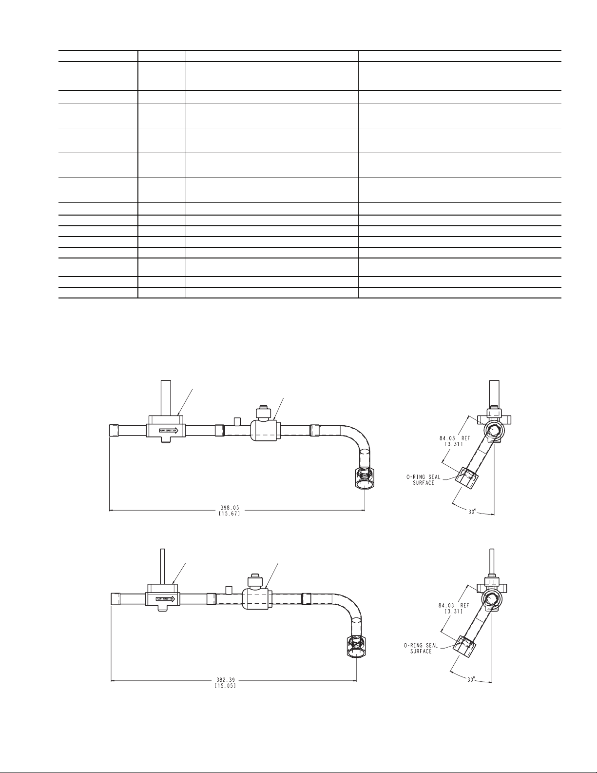
Table 2C — Contents of Accessory Kit, Part No. 00EFN900002900A
PART NUMBER QUANTITY DESCRIPTION USAGE
00PSN500175200A 2
30GX5034892 2 1 in. - 14 ORS x
Tube assembly including solenoid valve,
ball valve, and 90 degree bend tube assembly
1
/2 in. NPT adapter One per circuit. Cooler shell minimum load port.
00PPG000011600A 2 Solenoid coil assembly
One per circuit (Circuit A and B for 30XA325, 350,
circuit A and C for 30XA450, 500). Cooler shell
minimum load port, connect to 30GX5034892 adapter.
One per circuit. Plug onto solenoid valve stub
on 00PSN500171700A tube assembly.
KA66AA062 4 5/8 in. tube clamp
DE40BA705 21
1
/8 in. x 11/8 in. x 5/8 in. Tee
TH70400410 2Cable assembly
Secure minimum load piping to the frame
as required.
One per circuit. Discharge manifold on the side
of condenser coil V.
One per circuit. Connect to solenoid coil
assembly and terminal block TB5 in control box.
00PPN500000401A 4 No. 10 screw Mount tube clamps
32GB500432E 1 HGBP/Pump board Mount in control box
TH70400864 1 Harness assembly Wiring between TB5 and HGBP/Pump board
HH83ZB001 1 24V circuit breaker (CB14) Mount on display bracket in control box
A6X10004352 4 No. 8 screw Mount HGBP/Pump board
A6X10004434 4 Board mounting standoff
Mount HGBP/Pump board (325,350,450,500:
all voltages)
TH70400852 1 Communication cable assembly 30XA325,350,450,500: all voltages.
HY89TB010 3 Wire nut Splice communication cable
LEGEND
HGBP — Hot Gas Bypass
ORS — O-Ring Seal
TB — Terminal Block
SOLENOID VALVE
BALL VALVE
TUBE ASSEMBLY 00PSN500175200A
SOLENOID VALVE
TUBE ASSEMBLY 00PSN500171700AA
NOTE: Dimensions are in mm [in.].
Fig. 1 — Dimensions of Tube Assemblies Provided in Accessory Kit
a30-4499
BALL VALVE
a30-4500
3
Page 4

CKT BCKT A
CKT B
CKT B
CKT B
TT
T
T
CKT B
TTTT
T
UNIT SIZE: 180, 200
CKT A
CKT A
CKT B
CKT B
CKT A
CKT B
UNIT SIZE: 090-120
LEGEND
CB — Control Box
CKT — Circuit
T—Tee (braze tee in this dis-
charge manifold location)
1. Diagrams view 30XA from the cooler side.
2. Shaded area denotes the location of manifolds.
NOTES:
T
UNIT SIZE: 450, 500
CKT A
UNIT SIZE: 325, 350
CKT A
UNIT SIZE: 400 UNIT SIZE: 140, 160
T
Fig. 2 — Discharge Manifold Location for Minimum Load Piping Per Circuit
TTTT
UNIT SIZE: 260, 280, 300 UNIT SIZE: 220, 240
T
T
CKT A
CKT A
CKT C
T
CKT C
a30-4498
T
UNIT SIZE: 080
CKT A CKT B
T
4
Page 5

1/2 IN. NPT
A CIRCUIT
B CIRCUIT
1/2 IN. NPT
TUBE ASSEMBLIES
Fig. 3 — Typical Solenoid Valve Tube Assembly Installation
a30-4501
CUT 1-1/2 IN. OFF THE DISCHARGE MANIFOLD
Fig. 4 — Discharge Manifold Modification and Tee Brazing
BRAZE THE TEE IN THIS LOCATION
REMOVE TRIM PANEL
TO ACCESS
a30-4502
5
Page 6

Install HGBP/Pump Board and Control Wiring
1. Attach the solenoid coil assembly to the solenoid valve
plunger on the tube assembly for each circuit. One cable
assembly TH70400410 is supplied per circuit. Secure the
DIN connector end on the solenoid valve coil with the
screw in the connector. Verify the square rubber gasket is
in place to ensure connection remains watertight.
Take care connecting leads to terminal blocks. Incorrect
polarity will damage the control boards.
2. Route the other end of the cable to the main control panel
(where the display is located). For the circuit A solenoid,
connect leads to TB5-7 and TB5-13. For the B circuit
solenoid, connect leads to TB5-8 and TB5-13. For the C
circuit solenoid (30XA400-500 only), connect the leads
to TB5-6 and TB5-13. In all cases, the black wire from
the solenoid must be connected to TB5-13 to ensure
correct polarity.
3. Set the board address of the HGBP/Pump Board by positioning the dual in-line package (DIP) switches to the
correct settings. See Fig. 5. Mount the HGBP/Pump board
in the main control panel with the No. 8 screws provided
(mounting standoffs required for 30XA080-120: 200 v,
230 v, 380 v and 30XA140-500: all voltages). See Fig. 6A
and 6B for the board mounting location.
4. Mount the 24-v circuit breaker (CB14) in the CB14
mounting hole on the display bracket. See Fig. 6A and 6B
for the mounting hole location.
5. Connect the 24-v power from TB10-X1 (30XA080-120:
460 v, 575 v only) or TB11-X1 (30XA080-120: 200/230 v
and 30XA140-500: all voltages) to CB14 with the
provided red wire in the harness assembly. Find two 2-pin
plugs marked J1-11,12 with red and brown wires in the
harness assembly. Connect the plug to the HGBP/Pump
board J1 with the red wire connected to CB14 and the
brown wire connected to TB10-X2 (30XA080-120: 460 v,
575 v only) or TB11-X2 (30XA080-120: 200/230 v and
30XA140-500: all voltages). See Fig. 7.
6. Using harness TH70400864 provided in the kit, connect
TB5 pins 6 (30XA400-500 only), 7, 8, and 13 to HGBP/
Pump board J2 CH3, CH4 and J3 CH5 (30XA400-500
only). Use the pins inside TB5. See Fig. 5.
7. For 30XA080-120: 200/230 v, 380 v and 30XA140-500:
all voltages, disconnect the 3 pin plug on MBB J9B (or
EMM board J9A) for communication and plug it in to the
HGBP/Pump board J9. Use the additional communication cable assembly TH70400852 provided in the kit to
connect between HGBP/Pump board J9 and MBB J9B
(or EMM board J9A when EMM board exists). The communication cable in the TH70400864 harness will not be
used. For 30XA080-120: 460 v, 575 v, connect the 3 pin
plug of the communication cable in the TH70400864
harness to the HGBP/Pump board J9 and splice the other
end of the cable to the communication network using the
wire nuts provided in the kit. Be sure to splice the wires
with same color together to ensure correct polarity.
Fig. 5 — HGBP/Pump Board Address Switch and
a30-4503
Wiring for Minimum Load Solenoid Output
CB14
HGBP/PUMP
BOARD
a30-4504
Fig. 6A — HGBP/Pump Board and CB14 Mounting Location
(30XA080-120: 200 v, 230 v, 380 v and 30XA140-500: all voltages)
6
Page 7

TOUC H
PILOT
DISPLAY
Fig. 6B — HGBP/Pump Board and CB14 Mounting Location
TB10-X2 OR TB11-X2
CB14
(30XA080-120: 460 v, 575 v)
BRN
HGBP/PUMP
BOARD
a30-4505
TB10-X1 OR TB11-X1
Fig. 7 — HGBP/Pump Board 24 v Power Wiring
RED
CB14
3.2 AMPS
BRN
RED
FIOP/ACCESSORY
J1
2
12
1
11
HGBP/
PUMP
BOARD
a30-4506
7
Page 8

Configure Unit for Minimum Load Control —
The controls must be configured for the minimum load control
operation. Use the Touch Pilot™ or the Navigator™ display to
configure the system. Refer to the 30XA Controls, Start-Up,
Operation, Service, and Troubleshooting manual for additional
information.
Complete the following steps to configure minimum load control with the Touch Pilot display:
1. Ensure the unit is in Local Off operating mode by looking
at the upper left hand corner of the group display. If the
unit is not in Local Off mode, press the Start/Stop button
to switch to the Local Off operating mode.
2. Press the main menu button on the bottom line of the
display, and then select Service→ Factory to navigate to
the factory table.
3. Scroll down the screen by pressing the Scroll Down
button or the Page Down button until Hot Gas
Bypass Select is displayed on the screen. Press Hot Gas
Bypass Select to display the Point Data dialog.
4. Press the Modify button . If the login menu is displayed, log in with the password. The default password is
3333. Press the OK button to confirm the input. The
value of hgbp_sel will display. Select Yes and press
the OK button to confirm the input.
5. Press the Home button on the bottom line of the display. A save confirmation menu will display. Press the
OK button to confirm the action.
6. Wait 10 seconds and cycle the control power using the
Emergency On/Off switch (SW2).
The chiller is now configured for minimum load valve control.
Complete the following steps to configure minimum load con-
trol with the Navigator display:
1. Set the Enable/Off/Remote switch to the Off position.
2. Press until the screen is blank and use the
ESCAPE
arrow key to select the Configuration mode LED.
3. Press , then use the arrow key to select the
ENTER
sub-mode ‘UNIT’, then press the key.
ENTER
4. Press the down arrow key until ‘HGBP’ is displayed.
5. Press the key. If the login menu is displayed,
ENTER
log in with the password. The default password is 0 1 1 1.
Use the arrow keys to change each number’s value. Press
the key after each number until finished.
ENTER
6. Press the key so that ‘No’ flashes.
ENTER
7. Use the arrow keys to change the value to ‘Yes.’
8. Press the key.
9. Press the key until ‘DISP’ is displayed. Wait
ENTER
ESCAPE
10 seconds and cycle the control power using the Emergency On/Off switch (SW2).
The chiller is now configured for minimum load valve control.
Test Minimum Load Relay Output — Use the Touch
Pilot or Navigator display’s service test mode and the instructions given in their Controls, Start-Up, Operation, Service, and
Troubleshooting manuals to verify proper operation of the
solenoid(s).
For the Touch Pilot display:
1. Ensure the unit is in Local Off operating mode by looking
at the upper left hand corner of the group display. If the
unit is not in the Local Off mode, press the Start/Stop button to switch to the Local Off operating mode.
2. Press the Main Menu button on the bottom line of
the display and then select Status→ Quick Test Enable.
3. Press the Force button . If the login menu is displayed, log in with the password. The default password is
3333. Press the OK button to confirm the input.
4. The value of qck_test1 will display. Select On and press
the OK button to confirm the input.
5. Scroll down the screen by pressing the scroll down button
or the page down button until Cir. A Hot Gas
Bypass is displayed on the screen. Press Cir. A Hot Gas
Bypass Select to display the Point Data dialog.
6. Press the Force button . Select On and press the OK
button to confirm input.
7. Verify that the Cir. A minimum load valve (MLV) solenoid is energized.
8. Proceed to Cir. B Hot Gas Bypass and Cir. C Hot Gas Bypass (30XA400-500 only) by pressing the page down
button . Repeat Steps 5-7 for Cir. B MLV and Cir. C
MLV.
9. Use the page up button to return to the top of the table and select Quick Test Enable.
10. Press the Force button .
11. Select Off and press the OK button to disable Quick
Tes t.
12. Once the outputs have been tested, the installation is complete. Return the Touch Pilot to Local Off operating
mode.
For the Navigator display:
1. Set the Enable/Off/Remote switch to the Off position.
2. Press until the screen is blank and use the
ESCAPE
arrow key to select the Service Test mode LED.
3. Press , then use the arrow key to select the
ENTER
sub-mode ‘QUIC’, then press the key.
ENTER
4. Press the down arrow key until ‘HGP.A’ is displayed.
5. Press the key. If the login menu is displayed,
ENTER
log in with the password. The default password is 0 1 1 1.
Use the arrow keys to change each number’s value. Press
the key after each number until finished.
ENTER
6. Press the key so that ‘Off’ flashes.
ENTER
7. Use the arrow keys to change the value to ‘On.’
8. Press the key.
ENTER
9. Verify that the Cir. A minimum load valve (MLV)
solenoid is energized.
10. Proceed to ‘HGP.B’ and ‘HGP.C’ (30XA400-500 only)
and repeat Steps 4-9 for Cir. B MLV and Cir. C. MLV.
11. Once the outputs have been tested, the installation is complete. Return the Enable/Off/Remote contact switch to the
desired position.
Copyright 2006 Carrier Corporation
Manufacturer reserves the right to discontinue, or change at any time, specifications or designs without notice and without incurring obligations.
Book 2
Ta b 5 c
Catalog No. 04-53300010-01 Printed in U.S.A. Form 30XA-6SI Pg 8 12-06 Replaces: New
 Loading...