

Page 1
AQUASNAP
30RA/RH “B”
30RY/RYH “B”
PRO-DIALOG Control
Operation and maintenance instructions
Page 2

TABLE OF CONTENTS
1 - SAFETY CONSIDERATIONS..................................................................................................................................................4
1.1 - General .................................................................................................................................................................................4
1.2 - Avoid electrocution ..............................................................................................................................................................4
2 - GENERAL DESCRIPTION ......................................................................................................................................................4
2.1 - General .................................................................................................................................................................................4
2.2 - Abbreviations used ...............................................................................................................................................................4
3 - HARDWARE DESCRIPTION..................................................................................................................................................5
3.1 - General .................................................................................................................................................................................5
3.2 - Electrical supply to boards ...................................................................................................................................................5
3.3 - Light emitting diodes on boards...........................................................................................................................................5
3.4 - The sensors ...........................................................................................................................................................................5
3.5 - The output controls...............................................................................................................................................................5
3.6 - Connections at the user's terminal block ..............................................................................................................................6
3.6.1 - General description ......................................................................................................................................................6
3.6.2 - Volt-free contact on/off/cooling/heating without multiplexing ..................................................................................8
3.6.3 - Volt-free contact on/off/cooling/heating with multiplexing........................................................................................8
3.6.4 - Demand limit or setpoint volt-free contact for single-circuit units .............................................................................8
3.6.5 - Demand limit volt-free contact for dual-circuit units ..................................................................................................8
3.6.6 - Water setpoint selection volt-free contact with multiplexing for dual-circuit units....................................................8
4 - SETTING UP PRO-DIALOG CONTROL ..............................................................................................................................9
4.1 - Local interface general features............................................................................................................................................9
4.2 - Unit start/stop control .........................................................................................................................................................10
4.2.1 - Description................................................................................................................................................................. 10
4.2.2 - Stopping the unit in local mode .................................................................................................................................10
4.2.3 - Starting unit and selecting an operating type............................................................................................................. 10
4.3 - Menus .................................................................................................................................................................................11
4.3.1 - Selecting a menu ........................................................................................................................................................11
4.3.2 - Selecting a menu item................................................................................................................................................ 11
4.3.3 - Modifying the value of a parameter/access to a sub-menu........................................................................................11
4.3.4 - Expand display...........................................................................................................................................................12
4.3.5 - Description of the Information menu.........................................................................................................................15
4.3.6 - Description of the Temperatures menu......................................................................................................................17
4.3.7 - Description of the Pressures menu.............................................................................................................................17
4.3.8 - Description of the Setpoints menu............................................................................................................................. 17
4.3.9 - Description of the Inputs menu..................................................................................................................................18
4.3.10 - Description of the Outputs/Tests menu ...................................................................................................................19
4.3.11 - Description of the configuration menu ....................................................................................................................22
4.3.12 - Description of the Alarms menu ..............................................................................................................................28
4.3.13 - Description of the Alarms History menu .................................................................................................................28
4.3.14 - Runtime menu description .......................................................................................................................................28
2
Page 3

5 - PRO-DIALOG CONTROL OPERATION ............................................................................................................................29
5.1 - Start/stop control ................................................................................................................................................................29
5.2 - Heating/cooling operation ..................................................................................................................................................30
5.2.1 - General.......................................................................................................................................................................30
5.2.2 - Heating/cooling selection ..........................................................................................................................................30
5.3 - Evaporator water pump control ..........................................................................................................................................31
5.4 - Control interlock contact ....................................................................................................................................................31
5.5 - Evaporator heater control ................................................................................................................................................... 31
5.6 - Control point.......................................................................................................................................................................31
5.6.1 - Active setpoint ...........................................................................................................................................................31
5.6.2 - Reset...........................................................................................................................................................................33
5.7 - Demand limit ......................................................................................................................................................................33
5.8 - Night mode .........................................................................................................................................................................33
5.9 - Capacity control..................................................................................................................................................................33
5.10 - Head pressure control .......................................................................................................................................................33
5.11 - Defrost function................................................................................................................................................................34
5.12 - Additional electric heater stage control ............................................................................................................................34
5.13 - Control of a boiler ............................................................................................................................................................34
5.14 - Master/slave assembly...................................................................................................................................................... 34
5.15 - Controlling Pro-Dialog units with a System Manager .....................................................................................................34
6 - DIAGNOSTICS - TROUBLESHOOTING ............................................................................................................................35
6.1 - General ...............................................................................................................................................................................35
6.2 - Displaying alarms...............................................................................................................................................................35
6.3 - Resetting alarms .................................................................................................................................................................35
6.4 - Alarm codes........................................................................................................................................................................35
Each of the following drawings is replaced in the whole document by the corresponding explanation:
GENERAL LEGEND
Start/stop button
Return key
Down arrow
Up arrow
DELTA T. Example: temperature difference between entering and leaving heat exchanger temperatures
means character is flashing
The cover graphics are solely for illustration and forms no part of any offer for sale or any sale contract. The manufacturer
reserves the right to change the design at any time without notice.
3
Page 4

1 - SAFETY CONSIDERATIONS
2 - GENERAL DESCRIPTION
1.1 - General
Installation, start-up and servicing of equipment can be
hazardous if certain factors particular to the installation are not
considered: operating pressures, presence of electrical
components and voltages and the installation site (elevated
plinths and built-up up structures). Only properly qualified
installation engineers and highly qualified installers and
technicians, fully trained for the product, are authorised to
install and start-up the equipment safely. During all ser vicing
operations all instructions and recommendations which appear
in the installation and service instructions for the product, as
well as on tags and labels fixed to the equipment and
components and accompanying parts supplied separately, must
be read, understood and followed.
• Apply all standard safety codes and practices.
• Wear safety glasses and gloves.
• Use the proper tools to move heavy objects. Move units
carefully and set them down gently.
1.2 - Avoid electrocution
Only personnel qualified in accordance with IEC (International
Electrotechnical Commission) recommendations may be
permitted access to electrical components. It is particularly
recommended that all sources of electricity to the unit be shut
off before any work is begun. Shut off the main power supply
at the main circuit breaker or isolator.
IMPORTANT: This equipment uses and emits
electromagnetic signals. Tests have shown that the equipment
conforms to all applicable codes with respect to
electromagnetic compatibility.
RISK OF ELECTROCUTION: Even when the main circuit
breaker or isolator is switched off, certain circuits may still
be energised, since they may be connected to a separate power
source.
RISK OF BURNS: Electrical currents cause components to
get hot either temporarily or permanently. Handle power
cable, electrical cables and conduits, terminal box covers and
motor frames with great care.
Fan start-up:
ATTENTION: In accordance with the operating conditions
the fans can be cleaned periodically. A fan can start at any
time, even if the unit has been shut down.
2.1 - General
Pro-Dialog is a system for controlling single or dual-circuit
30RA/RY air-cooled liquid chillers or air-to-water 30RH/RYH
heat pumps. Pro-Dialog controls compressor start-up needed to
maintain the desired heat exchanger entering or leaving water
temperature. In cooling mode it controls the operation of the fans
to maintain the correct condensing pressure in each circuit. For
heat pump units it controls and optimises the defrost cycles of
each circuit in order to minimize the heating capacity
reduction. Safety devices are constantly monitored by ProDialog to ensure their safe operation. Pro-Dialog also gives
access to a Quick Test program covering all inputs and outputs.
All PRO-DIALOG controls can work in accordance with three
independent modes:
• Local mode: the machine is controlled by commands from
the user interface.
• Remote mode: the machine is controlled by remote
contacts (volt-free contacts).
• CCN mode: the machine is controlled by commands from
the Carrier Comfort Network (CCN). In this case, a data
communication cable is used to connect the unit to the
CCN communication bus.
The operating mode must be chosen with the Start/Stop button
described in section 4.2.1. When the PRO-DIALOG system
operates autonomously (Local or Remote mode) it retains all of
its own control capabilities but does not offer any of the
features of the CCN network.
2.2 - Abbreviations used
In this manual, the refrigeration circuits are called circuit A and
circuit B. The compressors in circuit A are labelled A1, A2 and
A3. Those in circuit B are B1, B2 and B3.
The following abbreviations are used fr equently:
CCN : Carrier Comfort Network
CCn : Operating type: CCN
LED : Light Emitting Diode
LOFF : Operating type: Local Off
L-On : Operating type: Local On mode
L-Sc : Operating type: Local On following a time schedule
MASt : Operating type: master unit (master/slave assembly)
rEM : Operating type: by remote contacts
SCT : Saturated Condensing Temperature
SIO : Sensor Bus (internal communication bus linking the
basic board to the slave boards)
SST : Saturated Suction Temperature
TXV : Thermal Expansion Valve
4
Page 5
3 - HARDWARE DESCRIPTION
5
6
8
3.2 - Electrical supply to boards
3.1 - General
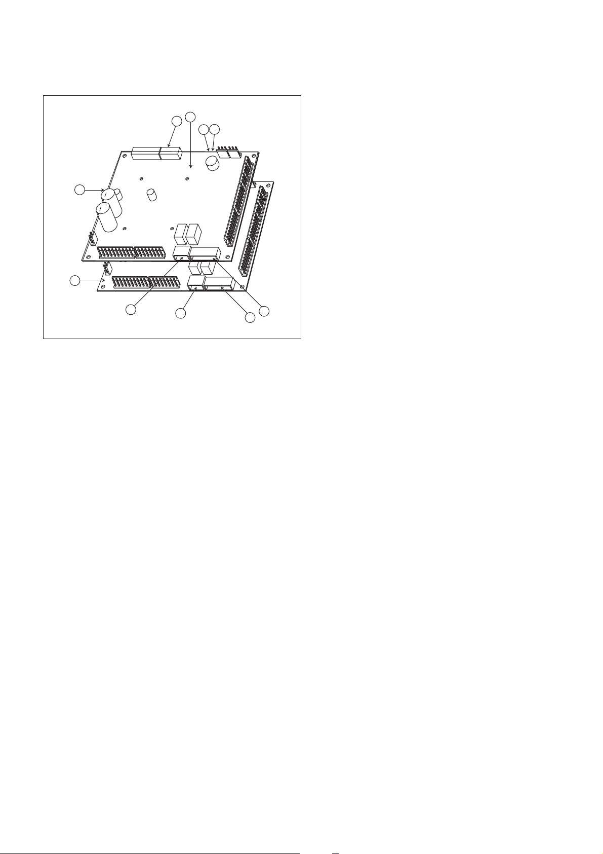
Figure 1
4
1
9
3
10
Legend
1 CCN connector
2 Red LED, status of the board
3 Green LED, communication bus SIO
4 Orange LED, communication bus CCN
5 Remote master board customer control connection contacts
6 Remote slave board customer control connection contacts
7 Master board customer connection relay outputs
8 Slave board customer connection relay outputs
9 Master NRCP basic board
10 Slave NRCP basic board
3
2
The control system consists of an NRCP-BASE board for
single-circuit units and two NRCP-BASE boards (a master and
a slave board) for dual-circuit units. Heat pump units equipped
with optional additional heater stages use an additional board,
type PD-AUX. All boards communicate via an internal SIO bus.
The NRCP-BASE boards continuously manage the information
received from the various pressure and temperature probes. The
NRCP-BASE master board incorporates the program that
controls the unit.
The user interface consists of two display blocks with up to 26
LEDs and 16 buttons (according to unit type). It is connected
to the main basic board and gives access to a full array of
control parameters.
All boards, except the PD-RCPM board, are supplied from a
common 24 V a.c. supply referred to earth.
CAUTION: Maintain the correct polarity when connecting
the power supply to the boards, otherwise the boards may be
damaged.
In the event of a power supply interrupt, the unit restarts
automatically without the need for an external command.
However, any faults active when the supply is interrupted are
saved and may in certain cases prevent a circuit or unit from
restarting.
3.3 - Light emitting diodes on boards
All boards continuously check and indicate the proper
operation of their electronic circuits. A light emitting diode
(LED) lights on each board when it is operating properly.
• The red LED flashing for a 2 second period on the NRCPBASE board indicates correct operation. A different rate
indicates a board or a software failure.
• On dual-circuit units or units equipped with optional
board, the green LED flashes continuously on all boards
to show that the board is communicating correctly over its
internal bus. If the LED is not flashing, this indicates a
SIO bus wiring problem.
• The orange LED of the master board flashes during any
communication via the CCN bus.
3.4 - The sensors
Pressure sensors
Two types of electronic sensors are used to measure the suction
and discharge pressure in each circuit.
Thermistors
The evaporator water sensors are installed in the entering and
leaving side. The outdoor temperature sensor is mounted below
the control box. An optional water system temperature sensor
can be used for master/slave assembly control (in the case of
leaving water control).
In heat pump units a sensor placed on an air heat exchanger
pipe ensures defrost operation.
5
Page 6

3.5 - The controls
3.6 - Connections at the user's terminal block
Evaporator pumps
The controller can regulate one or two evaporator pumps and
takes care of automatic change-over between pumps.
Evaporator heater
It protects the evaporator (and the pipe heater for units without
pump) against freezing if the unit is off.
Boiler
This relay output authorises start/stop of a boiler.
Condensate defrost heater
This heater is used for heat pump units and is located at the
bottom of the air heat exchanger of each circuit. It prevents ice
build-up, if defrost cycles are initiated at low outdoor
temperatures.
SINGLE-CIRCUIT UNITS
Description
Alarm relay output
Boiler relay output
Connector/channel
J3 / CH24
J3 / CH25
Terminal
30 - 31
37 - 38
Board
NRCP-BASE
NRCP-BASE
3.6.1 - General description
The contacts below are available at the user's terminal block on
the NRCP-BASE board (see figure 1). Some of them can only
be used if the unit operates in remote operating type (rEM).
The following table summarises the connections at the user’s
terminal block.
Remarks
Indicates alarms
Boiler start/stop control output.
See section 5.13.
Remarks
Volt-free contact 24 V a.c.
48 V d.c. max, 20 V a.c. or
V d.c., 3 A max, 80 mA min,
external power supply .
Contact 1:
start/stop/heat/cool
Contact 2:
start/stop/heat/cool
Contact 3:
demand limit selection or
setpoint selection
User safety loop input
Connection to CCN
J4 / CH8
J4 / CH9
J4 / CH10
J4 / CH11a
J12
32 - 33
63 - 64
73 - 74
34 - 35
1 - 2 - 3
NRCP-BASE
NRCP-BASE
NRCP-BASE
NRCP-BASE
NRCP-BASE
The contacts are used for unit start/stop and
heat/cool control. The y are only taken into
account if the unit is under remote operation
control (rEM).
See the description of these contacts in
sections 3.6.2 and 3.6.3.
Depending on the configuration, this dry
contact can be used for remote setpoint
selection or demand limit selection (see
sections 4.3.11.3 and 3.6.4).
- The remote setpoint selection contact is
only taken into account if the unit is in
remote control operating type.
- The remote demand limit selection contact
is active whatever the operating type of the
unit.
This contact is mounted in series with the
water flow control contact. It can be used for
any customer safety loop that requires that
the unit is stopped, if it is open.
If it is unused this contact must be bridged.
An RS-485 bus is used for connection to the
CCN.
- Pin 1: signal +
- Pin 2: ground
- Pin 3: signal -
Connector: 4 pin
WAGO 734-104 pitch 3.5.
One per board needed.
24 V a.c., 20 mA
Connector: 8 pin WAGO
734-168, pitch 3.5
Connector: 3 pin WAGO
231-303, pitch 5.08
6
Page 7

DUAL-CIRCUIT UNITS
Description
Alarm relay output
circuit A
Alarm relay output
circuit B
Boiler relay output
Contact 1:
start/stop/heat/cool
Contact 2:
start/stop/heat/cool
Contact 3:
demand limit selection
Contact 4:
demand limit selection
Contact 5:
setpoint selection
Control contact 6:
setpoint selection
User safety loop input
Connection to CCN
Connector/channel
J3 / CH24
J3 / CH24
J3 / CH25
J4 / CH8
J4 / CH9
J4 / CH10
J4 / CH10
J4 / CH8
J4 / CH9
J4 / CH11a
J12
Terminal
30A - 31A
30B - 31B
37 - 38
32 - 33
63 - 64
73 - 74
75 - 76
65 - 66
67 - 68
34 - 35
1 - 2 - 3
Board
Master NRCPBASE
Slave NRCPBASE
Master NRCPBASE
Master NRCPBASE
Master NRCPBASE
Master NRCPBASE
Slave
NRCP-BASE
Slave
NRCP-BASE
Slave
NRCP-BASE
Master
NRCP-BASE
Master
NRCP-BASE
Remarks
Indicates alarms/alerts f or circuit A*
Indicates alarms/alerts f or circuit B*
Boiler start/stop control output.
See section 5.13.
The contacts are used for unit start/stop and
heat/cool control. The y are only taken into
account if the unit is under remote operation
control (rEM).
See the description of these contacts in
sections 3.6.2 and 3.6.3.
These dry contacts are used for demand
limit selection. See description of these
contacts in section 3.6.5.
The remote demand limit selection contact is
active whatever the operating type of the
unit.
These dry contacts are used for setpoint
selection.
They are only taken into account if the unit is
in remote control operating type (rEM).
See the description of these contacts in
sections 3.6.6.
This contact is mounted in series with the
water flow control contact. It can be used for
any customer safety loop that requires that
the unit is stopped, if it is open.
If it is unused this contact must be bridged.
An RS-485 bus is used for connection to the
CCN.
- Pin 1: signal +
- Pin 2: ground
- Pin 3: signal -
Remarks
Volt-free contact 24 V a.c.
48 V d.c. max, 20 V a.c. or
V d.c., 3 A max, 80 mA min,
external power supply .
Connector: 4 pin
WAGO 734-104 pitch 3.5.
One per board needed.
24 V a.c., 20 mA
Connector: 8 pin WAGO
734-168, pitch 3.5
Connector: 3 pin WAGO
231-303, pitch 5.08
* The operation of these relays can vary depending on the user configuration. See section ‘Description of the User 2 configuration sub-menu’.
7
Page 8

3.6.2 - Volt-free contact on/off/cooling/heating without
multiplexing
If the automatic heating/cooling changeover function is not
selected (see sections 4.3.11.3, 5.1 and 5.2) the operation of
contacts 1 and 2 is as follows:
OFF ON cooling ON heating
Contact 1 Open Closed Closed
Contact 2 - Open Closed
Contact status not significant
3.6.3 - Volt-free contact on/off/cooling/heating with
multiplexing
If the automatic heating/cooling changeover function is
selected (see sections 4.3.11.3, 5.1 and 5.2) the operation of
contacts 1 and 2 is multiplexed:
OFF ON cooling ON heating ON auto
Contact 1 Open Closed Closed Open
Contact 2 Open Open Closed Closed
NOTE: The automatic changeover function (ON auto) selects
the cooling or heating mode based on the outdoor
temperature (see section 5.2).
3.6.5 - Demand limit volt-free contact for dual-circuit units
On dual-circuit units the operation of the demand limit
selection contacts is multiplexed. The demand limit setpoints are
adjustable in the setpoint menu (see section 4.3.8).
100% Limit 1 Limit 2 Limit 3
(no limit)
Contact 3 Open Closed Open Closed
Contact 4 Open Open Closed Closed
3.6.6 - Water setpoint selection volt-free contact with
multiplexing for dual-circuit units
On dual-circuit units the operation of the cold water or hot
water setpoint selection contacts is multiplexed. The set-points
are adjustable in the setpoint menu (see section 4.3.8). Auto
means that the active setpoint is determined by the setpoint
schedule (see section 5.6.1).
Cooling mode
Setpoint 1 Setpoint 2 Setpoint 3 Auto
Contact 5 Open Open Closed Closed
Contact 6 Open Closed Open Closed
Heating mode
Setpoint 1 Setpoint 2 Setpoint 3 Auto
Contact 5 Open Open Closed Closed
Contact 6 Open Closed Open Closed
3.6.4 - Demand limit or setpoint volt-free contact for singlecircuit units
On single-circuit units contact 3 determines the selection of
demand limit or setpoint, based on the configuration (see User
Configuration 1 menu).
Demand limit selection Setpoint selection
100% Limit 1 Setpoint 1 Setpoint 2
(no limit)
Contact 3 Open Closed Open Closed
8
Page 9
4 - SETTING UP PRO-DIALOG CONTROL
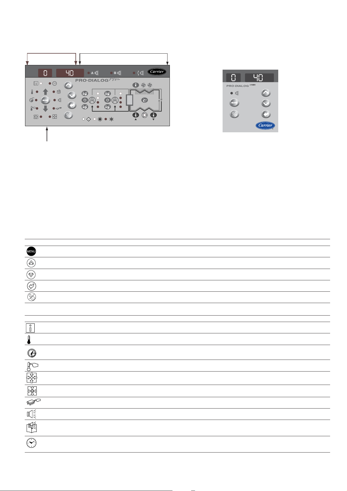
4.1 - Local interface general features
MAIN INTERFACE SUMMARY INTERFACE
MENU BLOCK
PRO-DIALOG PLUS INTERFACE
The local interface enables a number of operating parameters to
be displayed and modified.
• A two-digit display showing the number of the item
selected.
PRO-DIALOG JUNIOR INTERFACE
• A four-digit display showing the contents of the item
The interface consists of two distinct parts: the main interface
(left-hand section) and the summary interface (right-hand section).
selected.
• LEDs and buttons for unit start/stop, menu selection,
menu item selection and value adjustment.
Main interface
It gives access to all PRO-DIALOG data and operating functions.
It consists of:
PRO-DIALOG Junior interface: On some units the local user
interface consists only of a simplified main interface (left-hand
section) that is identical to the main interface described below,
but does not include the menu block diodes.
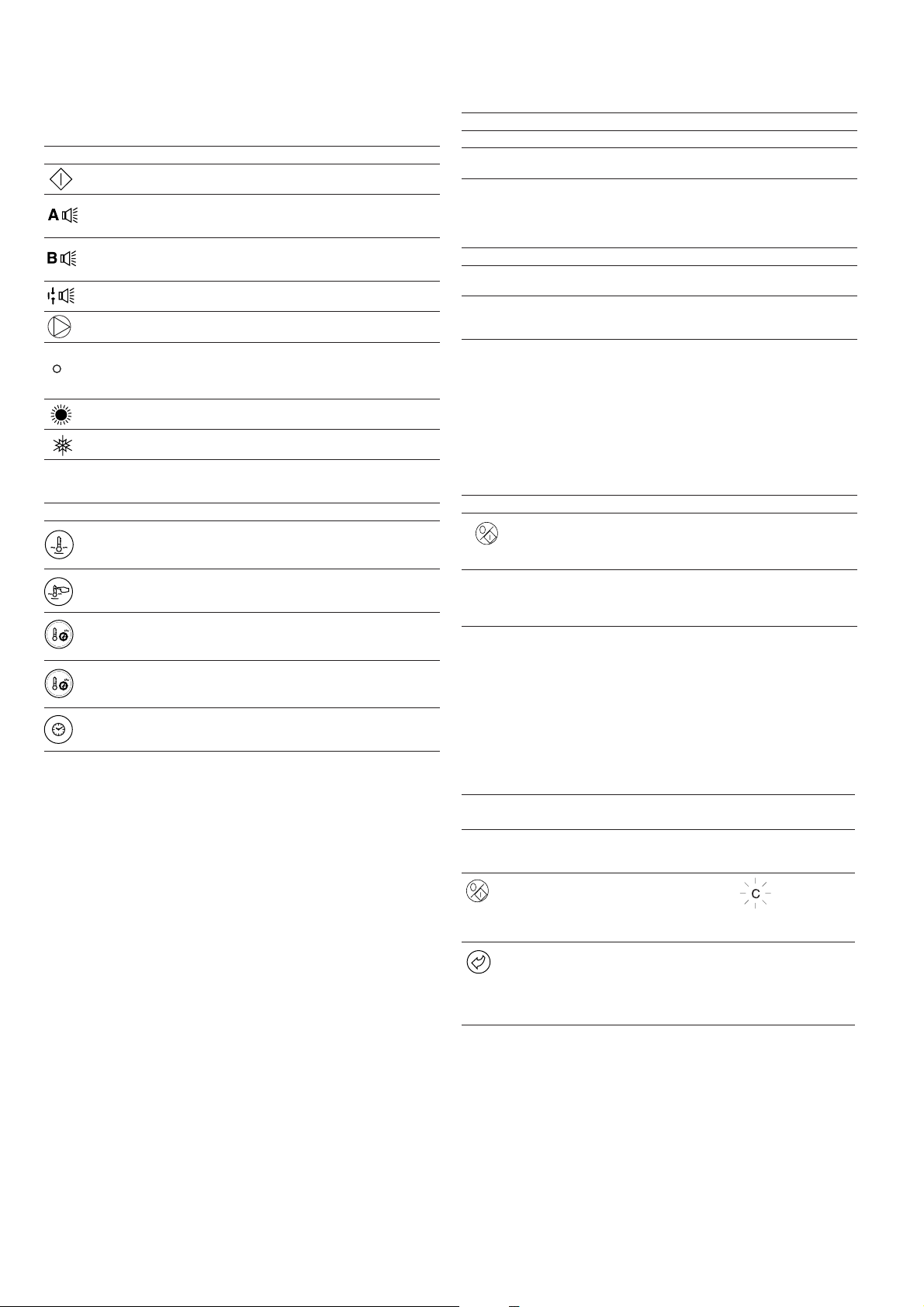
MAIN INTERFACE
BUTTON NAME DESCRIPTION
Menu Permits the selection of a main menu. Each main menu is represented by an icon. The icon is lit if active.
Up arrow Permits scrolling through the menu items (in the two-digit display). If the modification mode is active this button authorises
Down arrow Permits scrolling through the menu items (in the two-digit display). If the modification mode is active this button authorises
Enter Gives access to the modification mode, validates a modification or displays expanded item description.
Start/stop Authorises start or stop of the chiller in local mode or modification of its operating type.
MAIN INTERFACE MENU LED'S
LED* NAME DESCRIPTION INTERFACE DISLAY
INFORMATION menu Displays the general operating parameters for the unit. Information
increase of the value of any parameter.
decrease of the value of any parameter.
TEMPERATURES menu Displays the unit operating temperatures. Temperatures
kPa
* Not available on the PRO-DIALOG Junior interface.
PRESSURES menu Displays the unit operating pressures. Pressures
SETPOINTS menu Displays the unit setpoints and enables them to be modified. Setpoints
INPUTS menu Displays the status of the unit digital and analogue inputs. Inputs
OUTPUTS/TESTS menu Displays the status of the unit outputs and enables them to be tested. Outputs
CONFIGURATIONS menu Displays the unit configuration and enables it to be modified. Confguration
ALARMS menu Displays active alarms. Alarms
ALARMS HISTORY menu Displays the history of the alarms. History
RUNTIMES menu Displays the operating times and number of starts for the unit and the Runtimes
compressors.
9
Page 10
The summary interface (right hand section) includes a mimic
diagram of the unit, together with push-buttons and LEDs. It
gives quick access to the main operating parameters of the unit.
SUMMARY INTERFACE LEDs*
LED INDICATION WHEN LIT
Green LED:
The unit is authorised to start or is already running
Red LED:
- Lit: circuit A or unit shut down by alarm
- Flashing: circuit A or unit running with alarm present
Red LED:
- Lit: circuit B or unit shut down by alarm
- Flashing: circuit B or unit running with alarm present
Red LED:
Water flow switch default or user safety loc k open.
Green LED:
The evaporator pump is running.
Yellow LEDs:
From top to bottom - start/stop status of compressor A1, A2 and A3
or B1, B2 and B3. Flashing LED indicates that the circuit is in the
protection or defrost mode (A or B).
Green LED:
The unit operates in heating mode.
Green LED:
The unit operates in cooling mode.
* Not available on the PRO-DIALOG Junior interface.
SUMMARY INTERFACE PUSH BUTTONS*
BUTTON DISPLAY
Blue button: evaporator leaving or entering water temperature in °C
Gray button: outdoor air temperature in °C
Control point (setpoint + reset) in °C
Press 1: circuit A/B discharge pressure in kPa
Press 2: circuit A/B saturated condensing temperature in °C
Press 1: circuit A/B suction pressure in kPa
Press 2: circuit A/B saturated suction temperature in °C
Press 1: compressor A1/B1 operating hours in h/10 or h/100
Press 2: compressor A2/B2 operating hours in h/10 or h/100
Press 3: compressor A3/B3 operating hours in h/10 or h/100
* Not available on the PRO-DIALOG Junior interface.
4.2 - Unit start/stop control
4.2.1 - Description
The unit start/stop can be controlled by one of the following
methods:
• Locally on the actual unit (Local control type)
• By remote control with the aid of user contacts (remote
control type)
• By CCN control with the aid of the CCN (CCN control
type)
The main interface includes a Start/Stop button which can be
used to stop or start the unit in the local operating type or to
select the remote or CCN operating type.
The following operating types can be selected using the
Start/Stop button:
OPERATING TYPES
4 DIGIT DISPLA Y DESCRIPTION
LOFF Local Off. The unit is halted in local mode.
L-On Local On. The unit is in local control mode and is
L-Sc* Local On - timer control. The unit is in local control
CCN* CCN. The unit is controlled by CCN commands.
rEM* Remote. The unit is controlled b y remote control
MAST* Master Unit. The unit runs as a master in a two unit
Legend
* Displayed if the configuration requires it.
Section 5.1 gives a more detailed description of the commands to start/stop
the unit, analysed by operating type.
authorised to start.
mode. It is authorised to start if the period is occupied.
If the timer program for unit operation is unoccupied,
the unit remains shut down until the period becomes
occupied.
contacts.
lead/lag arrangement. This is displayed if the unit is
configured for master/slave control.
4.2.2 - Stopping the unit in local mode
The unit can be stopped in local mode at any time by pressing
the Start/Stop button.
TO STOP THE UNIT
BUTTON ACTION 2-DIGIT DISPLAY 4-DIGIT DISPLAY
Press the Start/Stop C LOFF
button for less than
4 seconds (one short
press is enough).
If the button is t LOFF
released, the unit stops
without the need for
further action.
4.2.3 - Starting unit and selecting an operating type
The unit can be started in local mode, or unit operating type
can be changed at any time using the Start/Stop button. In the
example that follows, the unit is stopped (LOFF) and the user
wants to start the unit in local mode.
START UP WITH THE PREVIOUSLY USED OPERA TING TYPE WHEN THE UNIT
IS STOPPED IN LOCAL MODE (LOFF)
BUTTON ACTION
The unit is in local stop mode. The
previously used operating type is local on
(L-ON)
Press the Start/Stop button for 4 seconds
(one short press-down is sufficient). L-ON
illuminates immediately. "C" flashes in the
2-digit display to show that the controller is
awaiting confirmation.
Press the Enter button to confirm the
operating type. "t" is displayed in the 2-digit
display to indicate the operating type
selected. If the Enter button is not pressed
soon enough, the controller will cancel the
change and remain in the stop mode.
2-DIGIT 4-DIGIT
DISPLAY DISPLAY
LOFF
L-On
t L-On
The available operating types are described in the following
table.
10
Page 11

CHANGING THE OPERATING TYPE
BUTTON ACTION
Continually press the operating type
selection button for more than 4 seconds.
Hold down the Start/Stop button.
The available operating types are displayed
one by one until the button is released.
Release the Start/Stop button if the
operating type you want is displayed (in this
example L-On). "C" flashes in the 2-digit
display to show that the controller is
awaiting confirmation.
Press the Enter button to confirm the
operating type selected (in this example:
L-On). "t" is displayed in the 2-digit display
to indicate the operating type selected. If the
Enter button is not pressed soon enough,
the controller will cancel the change and
continue to use the previous operating type.
2-DIGIT 4-DIGIT
DISPLAY DISPLAY
C LOFF
L-On
L-Sc
rEM
L-On
t L-On
4.3 - Menus
4.3.1 - Selecting a menu
The MENU button authorises you to select a menu from the 10
main menus that are available. Each time you press this button
one of the 10 LEDs lights up in turn alongside each of the
icons representing a main menu. The active menu is the one
against which the LED is lit. If a menu is empty then its LED is
not lit. To scroll quickly through the menus, hold the MENU
button down.
4.3.3 - Modifying the value of a parameter/access to a submenu
Press the Enter button for more than 2 seconds to enter the
modification mode or to select a sub-menu. This lets you correct
the value of an item or select a sub-menu with the aid of the up
and down Arrow buttons (if you are authorised to overwrite the
item concerned). When modification mode is activated, the LED
for the main menu to which the item belongs as well as the 2digit display flash in the menu block. Once the required value is
obtained, press the Enter button again to validate the c hange or
to acc e s s t h e sub-m e nu. The LED for the menu to which the
item and the 2-digit display belong then stops flashing,
indicating that modification mode no longer applies.
In modification mode, the value to be modified increases or
decreases in steps of 0.1 every time you press the Arrow
buttons. Holding one of these buttons down increases the rate
of increase or decrease.
NOTE: The access to a sub-menu may require entering a
password. This is automatically requested. See section
4.3.11.2.
The following example shows how to modify the value of item
1 in the Setpoint menu.
4.3.2 - Selecting a menu item
The up and down Arrow buttons let you scroll through the
menu items. Menu item numbers are displayed in the two-digit
display. The item number increases or decreases every time you
press the up or down Arrow button. The menu items that are not
in use or incompatible with the configuration are not displayed.
The value or status associated with the active item is displayed
in the four-digit display. To scroll quickly through the items,
hold the up or down Arrow button down.
The following example shows how to access item 3 in the
Pressures menu.
SELECTING A MENU ITEM
OPERATION PRESS MENU LED ITEM NUMBER
Press the MENU button until the 0
LED marked PRESSURE lights.
Note: On the PRO-DIALOG Junior
interface the menu LEDs are not
available. Instead, each time the
menu button is pressed, the name
of the active menu is dsplayed in
the 4-digit display. In this example,
press the MENU button until
PRESSURE is displayed in the
4-digit display.
BUTTON 2-DIGIT
DISPLAY
kPa
Press one of the Arrow buttons 1
until the two-digit display shows 3
(item number 3).
kPa
2
3
11
Page 12

4.3.4 - Expand display
Pressing the Enter button causes a 23 character text expansion to
be scrolled across the four-digit display. All user menus
provide an expansion of the current displayed parameters. If
the expansion is complete the four-digit display reverts to item
value. This function can be inhibited through the User
Configuration menu.
MODIFYING THE VALUE OF A PARAMETER
OPERA TION PRESS BUTTON MENU LED ITEM NUMBER ITEM VALUE
Hold on the MENU button until the LED for SETPOINT lights.
PRO-DIALOG Junior interface: Press the menu button, until SETPOINTS is
displayed in the 4-digit display
Press one of the Arrow buttons until the two-digit display shows 1
(item number 1- cooling setpoint 2).
The value for setpoint 2 is displayed in the four-digit display (6.0°C in this
example).
2-DIGIT DISPLAY 4-DIGIT DISPLAY
0
0 SEtPoint
1
1 6.0
Press the Enter button for more than 2 seconds to enable the value associated
with item 1 to be modified.
The Setpoint menu LED and the two-digit displa y flash indicating that modification
mode is active.
Keep pressing the Down Arro w b utton until the value 5.7 is displa y ed in the f ourdigit display. The Setpoint menu LED and the two-digit displa y keep flashing.
Press the Enter button again to validate the change. The new setpoint is 5.7°C .
The Setpoint menu LED and the two-digit display stop flashing, indicating that
modification mode no longer applies.
1
1
1
1
1 5.7
6.0
5.9
5.8
5.7
12
Page 13

MENU STRUCTURE
MAINTENANCE
[MAintEnAnCE]
ALARMS
RUNTIME 2
[RuntiME 2]
RUNTIME 1
[RuntiME 1]
[FACtorY]
FACTORY
SERVICE
[SErviCE]
SUB-SUB-MENUS
SUB-MENUS
HSM
[HSM]
[MAStEr SLAvE]
MASTER/SLAVE
[SErviCE 2]
SERVICE 2
[SErviCE 1]
SERVICE 1
[brodCASt]
BROADCAST
NOTE: The items in brackets show what is
displayed on the user interface.
MAIN MENUS
USER
[USEr]
[dAtE]
HOUR + DATE
[HoLidAy]
HOLIDAYS
SCHEDULE 2
[SCHEduLE 2]
SCHEDULE 1
[SCHEduLE 1]
USER 2
[USEr 2]
USER 1
[USEr 1]
[HoLidAy 1]
HOLIDAYS 1
[PEriod 1]
PERIOD 1
[PEriod 1]
PERIOD 1
[HoLidAy 3]
[HoLidAy 2]
HOLIDAYS 3
HOLIDAYS 2
[PEriod 3]
PERIOD 3
[PEriod 2]
PERIOD 2
[PEriod 3]
[PEriod 2]
PERIOD 3
PERIOD 2
SUB-SUB-SUB-MENUS
[HoLidAy 4]
HOLIDAYS 4
[PEriod 4]
PERIOD 4
[PEriod 4]
PERIOD 4
[HoLidAy 5]
HOLIDAYS 5
[PEriod 5]
PERIOD 5
[PEriod 5]
PERIOD 5
[HoLidAy 7]
HOLIDAYS 6
[PEriod 6]
PERIOD 6
[PEriod 6]
PERIOD 6
[HoLidAy 7]
HOLIDAYS 7
[PEriod 7]
PERIOD 7
[PEriod 7]
PERIOD 7
[HoLidAy 8]
HOLIDAYS 8
[PEriod 8]
PERIOD 8
[PEriod 8]
PERIOD 8
- - -
- - -
- - -
[HoLidAy15]
HOLIDAYS 15
[HoLidAy16]
HOLIDAYS 16
TATUS TEMPERATURES PRESSURES SETPOINTS INPUTS OUTPUTS CONFIGURATION ALARMS ALARMS HISTORY
13
Page 14

Menu tree structure
RUNTIMES
SUB-MENU:
Runtimes 1
SUB-MENU:
Runtimes 2
ALARMS HIST
Historic alarm code
1**
Historic alarm code
2**
ALARMS
Number of active
alarms/resets**
Active alarm code 1**
SUB-MENU:
Maintenance--
Historic alarm
code 3**
Historic alarm code
4**
Historic alarm code
Active alarm code 2**
Active alarm code 3**
Active alarm code 4**
-
-
5**
Historic alarm code
6**
Historic alarm code
Active alarm code 5**--
-
7**
Historic alarm code
8**
-
-
-
Historic alarm code
9**
Historic alarm code
10**--
-
-
-
-
-
-
-
-
-
-
-
-
-
-
-
-
-
-
-
-
MENU
CONFIG
SUB-MENU: User
Configuration (USEr)
SUB-MENU:
Service Configuration
OUTPUTS
Compressor status
circuit A
Compressor status
circuit B*
INPUTS
Contact 1: on/off/
heating/cooling
Contact 2: on/off/
heating/cooling
SETPOINTS
Cooling setpoint 1
Cooling setpoint 2
PRESSURES
Discharge pressure
circuit A
Suction pressure
circuit A
(SErviCE)
SUB-MENU:
Factory Configuration
(FACtorY)--
Two-speed fan
status circuit A
Two-speed fan
Contact 3: demand
limit/setpoint
selection
Contact 4: demand
Heating setpoint 1*
Heating setpoint 2*
Discharge pressure
circuit B*
Suction pressure
-
status circuit B*
Single-speed fan
status, crt A + B*
Water pump 1
limit selection*
Contact 5: setpoint
selection*
Contact 6: setpoint
Heating setpoint 3*
Auto changeover
circuit B*--
-
-
status*
Water pump 2
status*
Water heat
selection*
Safety loop status
Water pump
threshold (heating
mode)*
Auto changeover
threshold (cooling
mode)*
Setpoint demand
-
-
-
-
exchanger + air heat
exchanger heater
status, circuit A-Alarm circuits A and
operation contact
status*
Fault contact, com-
pressor, circuit A*
Fault contact, com-
limitation 1*
Setpoint demand
limitation 2*
Setpoint demand
-
-
-
B status
Boiler status*
pressor, circuit B*--
limitation 3*
Ramp loading*
-
-
-
-
Speed, fan A in %*
Speed, fan B in %*
Reversing valve,
circuit A*
-
-
Cooling - zero reset
threshold*
Cooling - full reset
threshold*
Cooling - full reset
value*
-
-
-
-
-
-
Reversing valve,
circuit B*
Status, heater
stages*
Local interface test
-
-
-
Heating - zero reset
threshold*
Heating - full reset
threshold*
Heating - full reset
value*
-
-
-
14
TEMP
Evaporator water
entering temp.
Evaporator water
STATUS
Default display
Mode
1
0
ITEM
leaving temp.
Outdoor tempera-
ture
Chiller occupied
mode*
2
Saturated discharge
temperature circuit
A
Saturated suction
temp. circuit A
Saturated discharge
Minutes left
Cooling/heating
selection*
Cooling/heating
3
4
5
temperature circuit
B*
Saturated suction
temp. circuit B*
Defrost temperature,
status*
Unit capacity in%Capacity circuit
6
7
circuit A*
A in %*
Defrost temperature,
circuit B*
System water
temperature*--
Capacity circuit
B in %*
Heater stages in
%*
Present demand
8
9
10
limit in %
Present lag limit
in %*
11
-
-
-
Setpoint in local
control*
Setpoint
occupied mode*
Active setpoint
12
13
14
-
-
Control point
Controlled water
temperature
15
16
Legend
* Displayed if the configuration requires it
** Displayed if the alarm exists
- Not in use
Page 15

4.3.5 - Description of the Information menu
INFORMATION MENU (3)
ITEM FORMAT UNITS
0
±nn.n °C
LOFF L-On L-Sc CCn rEM MASt -
OFF rEADY dELAY -
StOPPing running triPout OvErridE dEFrOSt -
OCCUPIEd UNOCCUPIEd -
COOL HEAT StAndbY BotH -
ALArM ALErt -
MAStEr SLAvE -
1 [1] nn
-
2 [2] -
occu
unoc
Forc
3 nn.n minutes
4 [2] -
HEAt COOL Auto -
5 [2]
HEAt COOL StbY both -
Forc 6 nnn %
7 nnn %
8 [2] nnn %
9 [2] nnn %
10 nnn
Forc %
11 [2] nnn %
12 [2] -
SP-1
SP-2
SP-3
AUtO
13 [2] -
occu
unoc
Forc
DESCRIPTION
Automatic display mode. It cycles through the following displays:
1: Controlled water temperature: temperature of the water that the unit tries to maintain at the control point.
2: Unit operating type
Local Off
Local On
Local On - based on unit clock. Displayed if the CCN/clock board is installed.
CCN Control. Displayed if the CCN/clock board is installed.
Remote Control
Master unit
3: Unit status
Off: Unit is stopped and not authorised to start.
Ready: Unit is authorised to start
Delay: Unit is in delay at start-up. This delay is active after the unit has been switched on. The delay can be
configured in the User Configuration menu.
Stopping: Unit is currently stopping.
On: Unit is running or authorised to start.
Fault shutdown.
Limit: The operating conditions do not allo w total unit operation.
Defrost: One circuit is in defrost mode.
4. Unit occupied/unoccupied status
Occupied: Unit in occupied mode
Unoccupied: Unit in unoccupied mode
5. Heating/cooling operating mode
Cooling: Unit operates in cooling mode
Heating: Unit operates in heating mode
Standby: Unit is in auto cooling/heating changeover mode, and is in standby
Both: The unit operates in cooling (compressors) and heating (boiler). Only with HSM operation.
6: Alarm mode
Alarm: Unit is totally stopped because of failure.
Alert: Unit is in failure but not completely stopped.
7: Master/Slave status
Master: The master/slave control is active and the unit is the master
Slave: The master/slave control is active and the unit is the slave
Active mode codes. Each active mode is displayed in turn. This Item is masked when nil. Pressing the enter button when a mode
code is displayed causes a character text expansion to be scrolled accross the four-digit display. See the description in the following
table
This item indicates the current unit occupied/unoccupied mode. Displayed if the CCN/clock board is installed.
Occupied
Unoccupied
The value is displayed in turn with 'Forc' when the unit is in CCN control and if this variable if forced through CCN.
Start-up delay. This item indicates the minutes left before the unit can be started. This delay at start-up is alw ays active after the unit
has been switched on. The delay can be configured in the User Configuration 1 menu.
Heating/cooling on selection: This item is accessible in read/write, if the unit is in local control mode. It is only displayed, if the unit is
in LOFF, L-On or L-Sc operating type. Display ed for heat pumps or if the unit controls a boiler.
Heating mode selection
Cooling mode selection
Automatic heating/cooling mode changeover selection. Only displayed if the auto changeover function is selected (User Configuration
1 menu).
Heating/cooling mode. This item indicates whether the unit is in cooling or heating. Displayed if the unit controls a boiler.
Heating
Cooling
Standby: Unit is in auto cooling/heating changeover mode, and is in standby.
Both: The unit operates in cooling (compressors) and heating (boiler). Only with HSM operation.
The value is displayed in turn with 'Forc' when the unit is in CCN control and if this variable if forced through CCN.
Total active capacity of unit. It is the percentage of compressor capacity used by the unit.
Total active cap acity of circuit A. It is the percentage of compressor capacity used by on circuit A..
Total active capacity of circuit B. It is the percentage of compressor capacity used by on circuit B. Dual-circuit units only.
Active electric heating stages. Only displayed for heat pumps and if the unit controls additional electric heating stages.
Present demand limit. This is the authorised operating capacity of the unit. See section 5.7.
The value is displayed in turn with 'Forc' when the unit is in CCN control and if this variable if forced through CCN.
Present lag chiller demand limit. Displayed when the master/slave control is selected.
Setpoint select in local mode. This point is read/write accessible. Displayed only when the unit is LOFF, L-On or L-Sc operating type.
SP-1 = cooling/heating setpoint 1
SP-2 = cooling/heating setpoint 2
SP-3 = heating setpoint 3
AUtO = active setpoint depends on schedule 2 (setpoint selection schedule). See section 5.6.1 & 4.3.11.6.
Setpoint occupied mode. Displayed if the CCN/clock board is installed.
Occupied: cooling setpoint 1 is active
Unoccupied: cooling setpoint 2 is active
The value shall be displayed in turn with 'Forc' when the unit is in CCN control and if this variable if forced through CCN.
15
Page 16

INFORMATION MENU (3) continued
ITEM FORMAT UNITS
14 ±nn.n °C
15 ±nn.n
Forc °C
16 ±nn.n °C
1 This item is masked when nil.
2 This item is displayed in certain unit configurations only.
3 Access to this menu is read-only except for item 10 that can be forced when the unit is in Local operating type.
DESCRIPTION OF OPERATING MODES (ITEM 1 OF THE INFORMATION MENU)
MODE # MODE NAME
1 Delay at start-up active
2 2nd cooling/heating setpoint active
3 3rd heating setpoint active
4 Setpoint reset active
5 Auto heating/cooling changeover
active
6 Demand limit active
7 Ramp loading active
8 Water or air heat exchanger
heater active
9 Evaporator pump reversal in effect
10 Evaporator pump periodic start
11 Night condensing mode
12, 13 Low suction temperature protection
14, 15 High pressure protection
16, 17 Defrost
18 Low water entering temperature
protection in heating mode
19, 20 Hot gas protection in heating mode
21, 22 Low suction temperature protection
in heating mode
23 Boiler active
24 Electric heating stages active
25 Unit in SM control
26 Master/slave link active
27 Low outside temperature protection
DESCRIPTION
Active setpoint. This is the current cooling/heating setpoint: it refers to cooling setpoint 1 or cooling/heating setpoint 2. See section
5.6.1.
Control point. This is the setpoint used by the controller to adjust the temperature of the leaving or entering w ater (according to
configuration).
Control point = active setpoint + reset. See section 5.6
The value is displayed in turn with 'Forc' when the unit is in CCN control and if this variable if forced through CCN.
Controlled water temperature. Water temperature that the unit tries to maintain at the control point.
DESCRIPTION
The delay at start-up operates after the unit has been switched on. If the delay has not expired, the mode is
active. The delay is configured in the User Configuration 1 menu.
The second cooling/heating setpoint is active. See section 5.6.1
The third heating setpoint is active. See section 5.6.1
In this mode, the unit uses the reset function to adjust the leaving water temperature setpoint. See section 5.6.
If the unit is in auto mode, the heating/cooling changeover is automatic, based on the outdoor temperature. See
section 5.2.
In this mode, the demand at which the unit is authorised to operate is limited. See section 5.7.
Ramp loading is active. In this mode, the rate of water temperature drop or rise (heating mode) in °C/min is limited
to a preset value in order to prevent compressor overloading. Ramp function must be configured (see User
Configuration 1 menu). Ramp values can be modified (see Setpoint menu).
The water or air heat exchanger heater is active. See section 5.5.
The unit is fitted with two evapor ator water pumps and reversal between pumps is in effect. See section 5.3.
The unit is stopped and the pump is started each day at 14.00 p.m. for two seconds. This function needs to be
configured in the User Configuration 1 menu. See section 5.3 & 4.3.11.3.
The night mode is active. Fan runs at low speed (if permitted by operating conditions) and unit capacity can be
limited. See section 5.8 & 4.3.11.3.
12 = circuit A & 13 = circuit B. Protection f or evaporator low suction temperature circuit is active. In this mode,
circuit capacity is not authorised to rise and the circuit can be unloaded.
14 = circuit A & 15 = circuit B. The unit is in cooling or heating mode. The circuit is in high pressure protection
mode because the HP protection threshold has been exceeded. Circuit has been unloaded and the circuit
capacity is not authorised to rise.
16 = circuit A & 17 = circuit B. The unit is in heating mode, and the defrost sequence is active on the relevant
circuit.
The unit is in heating mode and compressor start is not authorised, as the entering water temperature is below
10°C.
19 = circuit A & 20 = circuit B. The unit is in heating protection mode and hot gas discharge protection is active. In
this mode, the circuit capacity cannot increase, and the circuit may be unloaded or go into defrost mode.
21 = circuit A & 22 = circuit B. The unit is in heating mode and low suction temperature protection is active. In this
mode, circuit capacity is not authorised to rise and the circuit can be unloaded or go into defrost mode.
The unit controls a boiler and this is operating. See section 5.13.
The unit controls additional electric heating stages, and these are operating. See section 5.12.
Unit is in control of a System Manager (FSM, CSM III or HSM).
Unit is connected to a secondary unit by a master slave link and the master/slave modes are active.
The unit is in heating mode, and compressor start-up is not permitted, when the outside air temperature is lower
than the value configured in item 12 of the User 1 configuration menu. See the relevant section.
16
Page 17

4.3.6 - Description of the Temperatures menu
4.3.7 - Description of the Pressures menu
TEMPERATURES MENU [2]
ITEM FORMAT UNITS COMMENTS
0 ±nn.n °C Water heat exchanger entering water tempera-
1 ±nn.n °C Water heat exchanger leaving water tempera-
2 ±nn.n °C Outdoor temperature
3 ±nn.n °C Saturated discharge temperature, circuit A
4 ±nn.n °C Saturated suction temperature, circuit A
5 [1] ±nn.n °C Saturated discharge temperature, circuit B
6 [1] ±nn.n °C Saturated suction temperature, circuit B
7 [1] ±nn.n °C Defrost temperature, circuit A
8 [1] ±nn.n °C Defrost temperature, circuit B
9 [1] ±nn.n °C Chilled water system temperature. Used for
1 This item is displayed in certain unit configurations only
2 Access to this menu is read-only.
ture
ture
master/slave control.
4.3.8 - Description of the Setpoints menu
SETPOINTS MENU [2]
ITEM FORMAT UNITS RANGE
0 ±nn.n °C See table below
1 ±nn.n °C See table below
2 nnn °C See table below
3 [1] nnn °C See table below
4 [1] nn.n °C See table below
5 [1] ±nn.n °C 3.8 to 50
6 [1] ±nn.n °C 0 to 46
7 nnn % 0 to 100
8 [1] nnn % 0 to 100
9 [1] nnn % 0 to 100
10 ±nn.n °C/min 0.1 to 1.1
11 [1] ±nn.n °C See table below
12 [1] ±nn.n °C See table below
13 [1] ±nn.n °C See table below
14 [1] ±nn.n °C See table below
15 [1] ±nn.n °C See table below
16 [1] ±nn.n °C -16 to 16
COMMENTS
This item lets you display and modify Cooling setpoint 1*
This item lets you display and modify Cooling setpoint 2*
This item lets you display and modify Heating setpoint 1*, only display ed for heat pumps.
This item lets you display and modify Heating setpoint 2*, only display ed for heat pumps.
This item lets you display and modify Heating setpoint 3*, only display ed for heat pumps.
Automatic changeover threshold, cooling mode. This item lets you display and modify the outdoor
temperature threshold at which the unit changes over in cooling mode. See section 5.2. Displayed only if
the auto cooling/heating changeover function is selected.
Automatic changeover threshold, heating mode. This item lets you display and modify the outdoor
temperature threshold at which the unit changes over in heating mode. Displayed only if the auto cooling/
heating changeover function is selected and if the unit is a heat pump. The heating threshold must be
3.8°C below the cooling threshold, otherwise the new setpoint will be rejected.
Demand limit 1 setpoint. Limitation by volt-free contact. This item is used to define the maximum
capacity that the unit is authorised to use, if the demand limit contact(s) activate limit 1. Contact control
depends on the unit type and configuration. See sections 3.6.4 and 3.6.5.
Demand limit 2 setpoint. Limitation by volt-free contact. This item is used to define the maximum
capacity that the unit is authorised to use, if the demand limit contact(s) activate limit 2. Contact control
depends on the unit type and configuration. Displayed and used only for dual-circuit units. See section
3.6.5 for the contact control description.
Demand limit 3 setpoint. Limitation by volt-free contact. This item is used to define the maximum
capacity that the unit is authorised to use, if the demand limit contact(s) activate limit 3. Displayed and
used only for dual-circuit units. See section 3.6.5 for the contact control description.
Cooling or heating ramp loading rate. This parameter is only accessible if the ramp function is
validated in the User Configuration 1 menu. This item refers to the rates of temperature drop in °C in the
evaporator. When capacity loading is effectively limited by the ramp, mode 7 is active.
Zero reset threshold, cooling mode**
Full reset threshold, cooling mode**
Full reset value, cooling mode**
Zero reset threshold, heating mode**
Full reset threshold, heating mode**
Full reset value, heating mode**
PRESSURES MENU [2]
ITEM FORMAT UNITS COMMENTS
0 nnnn kPa Discharge pressure, circuit A .
Relative pressure.
1 nnn kPa Suction pressure, circuit A.
Relative pressure.
2 [1] nnnn kPa Discharge pressure, circuit B.
Relative pressure.
3 [1] nnn kPa Suction pressure, circuit B.
Relative pressure.
1 This item is displayed in certain unit configurations only.
2 Access to this menu is read-only
1 This item is displayed in certain unit configurations only.
2 All points contained in this table can be modified.
* Those setpoints can be used for entering or leaving water temperature control. By default the unit controls the evaporator entering fluid temperature.
Leaving fluid temperature control requires a parameter modification in the Service Configuration menu.
** These parameters are only accessible when reset based on OAT or delta T has been selected in the User Configuration 1 menu. See section 4.3.11.3 & 5.6.2.
17
Page 18

LEAVING WATER TEMPERATURE CONTROL
SETPOINT - °C R-22/R-407C
Minimum cooling value
Water 5.0
Medium brine 0.0
Brine -10.0
Maximum cooling value 20.0
Feedback setpoint, cooling 6.0
Minimum heating value 20.6
Maximum heating value 56.1
Feedback setpoint heating 48.0
ENTERING WATER TEMPERATURE CONTROL
SETPOINT - °C R-22/R-407C
Minimum cooling value
Water 10.0
Medium brine 6.1
Brine -3.9
Maximum cooling value 26.1
Feedback setpoint, cooling 12.0
Minimum heating value 14.4
Maximum heating value 50.0
Feedback setpoint heating 42.0
4.3.9 - Description of the Inputs menu
INPUTS MENU [2]
ITEM FORMAT UNITS
0 oPEn/CLoS -
COMMENTS
Remote contact 1 status.
If the auto cooling/heating changeover function is not selected (User Configuration 1), this contact is used to start and
stop the unit. If the auto cooling/heating changeover function is selected, this contact is multiplexed with contact 2 to
permit starting and stopping the unit and the selection of heating/cooling/auto. This contact is only v alid, if the unit is in
the remote operating control (rEM) mode. See section 3.6 for the description of the connections of this contact.
RESET THRESHOLDS IN COOLING OR HEATING MODE
Reset threshold Zero Full
Reset based on outdoor -10 to 51 °C -10 to 51 °C
air temperature
Reset based on 0 to 11.1 °C 0 to 11.1 °C
Delta T
1 [1] oPEn/CLoS -
2 oPEn/CLoS -
3 oPEn/CLoS -
4 [1] oPEn/CLoS -
5 [1] oPEn/CLoS -
6 [1] oPEn/CLoS -
7 oPEn/CLoS -
8 [1] b1b2b
9 [1] b1b2b
1 This item is displayed in certain unit configurations only
2 Access to this menu is read-only.
3
3
-
-
Remote contact 2 status.
If the auto cooling/heating changeover function is not selected (User Configuration 1), this contact is used to select the
heating or cooling mode. If the auto cooling/heating changeover function is selected, this contact is multiplexed with
contact 1 to permit starting and stopping the unit and the selection of heating/cooling/auto. This contact is only valid, if
the unit is in the remote operating control (rEM) mode. See section 3.6 for the description of the connections of this
contact.
Remote contact 3 status.
The operation of this contact depends on the unit type.
Single-circuit unit: this contact can be used either to limit unit demand or to select a setpoint, as described in User
Configuration. If this contact is used for selecting a setpoint it is only active if the unit is in the remote operating control
mode. If the contact is used to limit the demand of the unit, it is active in all operating types.
Open contact: unit capacity is not limited or unit control is based on setpoint 1.
Closed contact: unit capacity is limited at limit setpoint 1 or unit control is based on setpoint 2.
See section 4.3.11.3 for the configuration of contact 3 - section 5.6.1 for the description of the setpoint selection section 5.7 for the description of the demand limit function and 3.6 for the description of the connection of contact 3 for
single-circuit units.
Dual-circuit units: this contact is multiplexed with contact 4 to permit the selection of a demand limit point. This
contact is active in all operating types. See section 3.6.5 for the description of this contact and section 5.7 for the
description of the demand limit function.
Remote contact 4 status.
This contact is only used for dual-circuit units: this contact is multiplexed with contact 3 to permit selection of a
demand limit value. This contact is active in all operating types. See section 3.6.5 f or the description of this contact
and section 5.7 for the description of the demand limit function.
Remote contact 5 status.
This contact is only used for dual-circuit units: this contact is multiplexed with contact 6 to permit selection of a
setpoint. This contact is only active in the remote operating control mode. See section 3.6.6 for the description of this
contact and section 5.6.1 for the description of the setpoint selection function.
Remote contact 6 status.
This contact is only used for dual-circuit units: this contact is multiplexed with contact 5 to permit selection of a
setpoint. This contact is only active in the remote operating control mode. See section 3.6.6 for the description of this
contact and section 5.6.1 for the description of the setpoint selection function.
Interlock status. When this contact opens the unit stops or is prevented from starting and an alarm is created. This
contact is used to control the water flow . In addition, a customer safety device can be connected in series with this
contact (see section 3.6).
Water pump run contact status. When this contact opens while an evaporator pump has received a command to be
on then a pump failure alarm is tripped.
Compressor feedback contacts, circuit A b1 = feedback A1 b2 = feedback A2 b3 = feedback A3
Compressor feedback contacts, circuit B b1 = feedback B1 b2 = feedback B2 b3 = feedback B3
18
Page 19

4.3.10 - Description of the Outputs/Tests menu
4.3.10.1 - General
This menu displays the status of the controller outputs. Moreover, when the machine is fully stopped (LOFF) the outputs
can be activated for manual or automatic tests (the access to the
tests is password controlled).
4.3.10.2 - Menu description
OUTPUTS STATUS & TESTS MENU [2] [3]
ITEM FORMAT UNITS
0b
1 [1] b1b2b
2 StoP
3 [1] StoP
4 [1] b
5 [1] On
6 [1] On
7On
8b
9 [1] On
10 [1] nnn
11 [1] nnn
12 [1] b
1b2b3
tESt
FAIL
Good -
3
tESt
FAIL
Good -
LOW
HIGH
tESt -
LOW
HIGH
tESt -
1b2
OFF
tESt
FAIL
Good
Forc -
OFF
tESt
FAIL
Good
Forc -
OFF
tESt -
1b2
tESt -
OFF
tESt -
tESt %
tESt %
1b2
tESt
-
DESCRIPTION
Circuit A compressors, command status
b
= compressor A1
1
b2 = compressor A2
b3 = compressor A3
In test mode, the Arrow buttons display 001, 010 and 100 in succession, so as to force the status of the compressor outputs
in turn. During the test phase, power to the compressor is s witched on for 10 seconds only. It is then not possible to restart the
compressor for a further 30 seconds. When the test is completed the following is displayed:
- Fail: displayed if the test has failed because the compressor was not started or run in reverse rotation.
- Good: displayed if test was successful
Circuit B compressor, dual-circuit unit s only
b
= compressor B1
1
b2 = compressor B2
b3 = compressor B3
In test mode... as above
Two-speed fan status, circuit A
Stop = fan is stopped
Low = fan is in low speed
High = fan is in high speed
Two-speed fan status, circuit B
Stop = fan is stopped
Low = fan is in low speed
High = fan is in high speed
Single-speed fan status
b
= fan A2
1
b2 = fan B2
Only for dual-circuit units
Evaporator water pump #1 command status. Not displayed if the unit does not control a pump.
On: pump is running
Stop: pump is stopped
Forc: this item is displayed only when the unit is stopped locally (LOFF). selecting this item authorises turning on the
pump with no delay and for an unlimited length of time. The pump will remain on until any button of the user interface is
pressed: it is then immediately stopped. If the unit is in CCN control, then the pump status is displayed in turn with "Forc"
if the pump status if forced through CCN.
During the test phase, power to the pump is switched on for 10 seconds only. When the test is completed the f ollowing is
displayed:
- Fail: displayed if the test has failed because the pump was not started
- Good: displayed if the test was successful
Evaporator water pump #2 command status. Not displayed if the unit does not control a secondary pump.
On: pump is running
Stop: pump is stopped
Forc: this item is displayed only when the unit is stopped locally (LOFF). selecting this item authorises turning on the
pump with no delay and for an unlimited length of time. The pump will remain on until any button of the user interface is
pressed: it is then immediately stopped. If the unit is in CCN control, then the pump status is displayed in turn with "Forc"
if the pump status if forced through CCN.
During the test phase, ...as above
Water or air heat exchanger heater command status
See sections 5.5 and 5.11
Alarm output command status
b1 = alarm circuit A
b2 = alarm circuit B
In test mode, the Arrow buttons display 01 and 10 in succession, so as to force each alarm output status in turn.
Boiler command status. Displa yed if the unit controls a boiler. See section 5.13.
Variable fan speed, circuit A. Displayed if the unit controls a variable-speed fan.
Variable fan speed, circuit B. Dual-circuits only and if the unit controls a variable-speed fan.
4-way reversing cycle valve status. In test mode, the arrow keys successively display 01 and 10, in order to authorise the
test for each valve in turn.
b1 = valve circuit A
b2 = valve circuit B
This item is only displayed for heat pump units.
19
Page 20

OUTPUTS STATUS & TESTS MENU [2] [3] continued
ITEM FORMA T UNITS
13 [1] b
14 [1] YES -
15 Auto tESt -
1 This item is displayed in certain unit configurations only.
2 Testing authorised only if the unit is in Local Off and all compressors are off.
3 Password needed only for testing.
“Test” Displayed in turn with the item value during tests.
1b2b3b4
tESt
no tESt %
DESCRIPTION
Additional heating stage status.
b
= stage 1
1
b2 = stage 2
b3 = stage 3
b4 = stage 4
In test mode the arrow keys successively display 0001, 0010, 0100 and 1000 to force the status of each electric heating stage
in turn.
This item is only displayed for heat pump units controlling additional electric heater stages. See section 5.12.
Used for local interface test only . Lights or flashes all LEDs and blocks, so as to check that they are working properly .
Automatic test. Selecting this item activates the automatic test function.
4.3.10.3 - Manual tests
This function allows the user to test the outputs individually, if
the machine is completely shut down (LOFF). To carry out a
manual test use the arrow keys to access the output to be tested
and press the Enter key (longer than 2 seconds) to activate the
modification mode. The password is automatically requested, if it
has not previously been verified. The Outputs/Test LED on the
user interface begins to flash. Enter the desired test value and
again press Enter to start the test. 'TESt' is displayed on the 4digit display alternately with the value tested. The Outputs/Test
LED stops flashing. Press the Enter key or an arrow key to stop
the test.
4.3.10.4 - Automatic tests
The automatic test function verifies the integrity of the analogue entries and activates the outputs in sequence. For each test
't XX' is displayed on the user interface. 'xx' indicates the
number of the test in progress. When a test has been completed ,
the following test is automatically activated.
A message may appear, asking the operator for a validation
with the Enter key, if the control cannot automatically verify a
sensor value or an output status. If the value read or the output
status is incorrect, the operator must press a different key (not
the Enter key) to cancel the automatic test procedure.
If a test fails, an error message and an error code are displayed. The automatic test procedure is interrupted.
When all tests have been completed, an end-of-test message
appears.
The table below describes the messages shown on the user
interface during the automatic test sequence.
TEXT DESCRIPTION
Thermistor test failed [XX] Test number XX of the thermistor has failed
Pressure test failed [XX] Test number XX of the pressure sensor has
failed
Output test failed [XX] Output test number XX has failed
Input test failed [XX] Input test number XX has failed
Press enter if test [XX] correct Request for the operator to validate test XX
OAT [value] press enter if Request for the operator to validate the
test [XX] correct outdoor air temperature value displayed.
T est number XX
Auto test completed Automatic test completed
20
Page 21

The table below describes the different sequences of the
automatic test.
TEST NUMBER
0
1
2
3
4
5, 6
7, 8, 9
10, 11
12, 13, 14
15, 16, 17
18
19, 20, 21
22
23
24
25
26
27
28
29
30
31
32
33
34
35
36
37
38
DESCRIPTION
Outdoor temperature sensor test
Pressure sensor test - circuit A
Pressure sensor test - circuit B (dual-circuit units only)
Defrost sensor test - circuit A (heat pumps only)
Defrost sensor test - circuit B (dual-circuit heat pumps only)
Water flow switch test and primary pump test
Entering and leaving water temperature sensor test
Water system temperature sensor test (for master/slav e units equipped with this sensor only)
Water flow switch test and secondary pump test (for units equipped with a secondary pump only)
Test compressor A1, A2 (if applicable) , A3 (if applicable)
4-way reversing valve test, circuit A (heat pumps only)
Test compressor B1 (if applicab le), B2 (if applicable), B3 (if applicab le )
4-way reversing valve test, circuit B (dual-circuit heat pumps only)
Low-speed test, fan A1 (units not equipped with Varifan)
High-speed test, fan A1 (units not equipped with Varifan)
Low-speed test, fan A 2 (dual-circuit units not equipped with Varif an)
High-speed test, fan A2 (dual-circuit units not equipped with Varifan)
Fixed-speed test, fan A2 (f or circuits equipped with a second f an)
Fixed-speed test, fan B2 (for circuits equipped with a second fan)
Water and air heat exchanger heater test
Not used
Boiler output activation (if unit controls a boiler)
Additional electric heating stage 1 activation (if unit controls electric heating stages)
Additional electric heating stage 2 activation (if unit controls electric heating stages)
Additional electric heating stage 3 activation (if unit controls electric heating stages)
Additional electric heating stage 4 activation (if unit controls electric heating stages)
Alarm output A activation
Alarm output B activation
Automatic test completed
CONFIRMATION
yes
no
no
no
no
no
no
no
no
no
no
no
no
yes
yes
yes
yes
yes
yes
yes
yes
yes
yes
yes
yes
yes
yes
-
21
Page 22

The table below describes the faults that can be displayed
during the automatic test.
TEST FAULT
1
2
3
4
5
6
7
8
9
10
11, 12, 13; 14, 15
16, 17, 18, 19, 20
21
22, 23; 24, 25, 26
27
28
29
30
31
32
33
34
35
36
37
38
39
40
41
42
43
44
45
46
47
48
49
50
51
52
53
DESCRIPTION
Outdoor air thermistor outside range
Outdoor air value read not validated by operator
Low pressure transducer, circuit A, outside range
High pressure transducer, circuit A, outside range
Low pressure transducer, circuit B, outside r ange
High pressure transducer, circuit B, outside range
Defrost thermistor, circuit A, outside range
Defrost thermistor, circuit B, outside range
Water flow switch not open
Primary pump not started or water flow switch not
closed
Water entering temperature sensor outside range
Water leaving temperature sensor outside range
T emperature diff erence between entering and leaving
water sensors too high
Water system leaving temperature sensor outside
range
T emperature diff erence between the system entering
and leaving water sensors too high
Water flow switch not closed or primary pump not
stopped
Secondary pump not started or water flow switch not
closed
Water flow switch not closed or secondary pump not
stopped
Command fault; compressor A1
Command fault; compressor A2
Command fault; compressor A3
Command fault, 4-way reversing valve, circuit A
Command fault; compressor B1
Command fault; compressor B2
Command fault; compressor B3
Command fault, 4-way reversing valve, circuit B
Low-speed test, fan A1 not validated by the operator
High-speed test, fan A1 not validated by the operator
Low-speed test, fan B1 not validated by the operator
High-speed test, fan B1 not validated by the operator
Test fan A2 not validated by the operator
Test fan B2 not validated by the operator
Water heat exchanger heater and air heat exchanger
condensate heater test, circuit A not validated by the
operator
Air heat exchanger condensate heater, circuit B, not
validated by the operator
Boiler activation test not validated by the operator
Electric heating stage 1 activation test not validated
by the operator
Electric heating stage 2 activation test not validated
by the operator
Electric heating stage 3 activation test not validated
by the operator
Electric heating stage 4 activation test not validated
by the operator
Alarm relay output activation test, circuit A not
validated by the operator
Alarm relay output activation test, circuit B not
validated by the operator
4.3.11- Description of the configuration menu
4.3.11.1- General
This menu can be used to display and modify all configurations: Factory, Service and User. Only the User Configuration can
be modified by the end-user. The Factory, Service and master/
slave configurations are not described in this document. A
configuration can only be modified if the unit is fully stopped
(LOFF).
The menus User 1 [USEr 1] and User 2 [USEr 2] are password-protected. The other menus are directly accessible,
except if item 11 of the User 2 menu (password for all configurations) has been validated.
4.3.11.2 - Password
A password must be entered in order to access the test function
or to modify a configuration. It is automatically requested, if
necessary: 'EntEr PASS' is displayed on the 4-digit display and
the configuration menu LED flashes, indicating that the
modification mode is active. Press the arrow keys until the
value '11' is displayed on the 4-digit display. Press Enter to
validate this. The configuration menu LED stops flashing . If the
password is correct, 'Good' is displayed. If the password is
incorrect, 'PASS incorrEct' is displayed. The User password has
a default value of 11.
This value can be modified through the Service configuration.
The password can be entered if the unit is fully stopped,
otherwise 'ACCES dEniEd' (access denied) will be displayed on
the 4-digit display. The controller automatically deactivates the
password after 5 minutes without activity (i.e. no buttons
pressed) or after powering up.
22
Page 23

SUB-MENU USER CONFIGURATION
USER 1
ITEM
[USER1]
Return to previous menu
0
-
1
Ramp selection*
2
Start-up delay*
3
Water pump selection
4
Water pump changover
5
delay*
Pump shutdown in
6
standby mode
Control contact 3
7
selection*
Setpoint reset selection,
8
cooling mode
Setpoint reset selection,
8
heating mode*
Boiler selection
10
Boiler operation
11
threshold*
Operating threshold,
12
heating mode*
Electric heating stage
13
operation threshold*
Electric heating safety
14
stage threshold*
Electric heating stage
15
operation schedule*
Quick start-up, electric
16
heater stages in defrost
mode*
Automatic heating/cooling
17
changeover selection
Extended display
18
selection
USER 2
[USER2]
Return to previous
menu
Periodic pump startup
Night mode - start
hour
Night mode - end
hour
Night mode demand
limit
Night mode min.
demand
Alarm relay selection
Number clock 1
Number clock 2
CCN element
number
CCN bus number
Password for all user
configurations
-
Software version
number
-
-
-
-
-
* only displayed if configuration requires.
DATE
[dAtE]*
Return to previous
menu
Hour*
Day of the week*
Day and month*
Year*
-
-
-
-
-
-
-
-
-
-
-
-
-
-
SCHEDULE 1
[ScHEduLE 1MEnu]*
Return to previous menu
SUB-MENU:
Period 1 [PErIod 1]
SUB-MENU:
Period 2 [PErIod 2]
SUB-MENU:
Period 3 [PErIod 3]
SUB-MENU:
Period 4 [PErIod 4]
SUB-MENU:
Period 5 [PErIod 5]
SUB-MENU:
Period 6 [PErIod 6]
SUB-MENU:
Period 7 [PErIod 7]
SUB-MENU:
Period 8 [PErIod 8]
-
-
-
-
-
-
-
-
-
-
SCHEDULE 2
[ScHEduLE 2 MEnu]*
Return to previous
menu
SUB-MENU:
Period 1 [PErIod 1]
SUB-MENU:
Period 2 [PErIod 2]
SUB-MENU:
Period 3 [PErIod 3]
SUB-MENU:
Period 4 [PErIod 4]
SUB-MENU:
Period 5 [PErIod 5]
SUB-MENU:
Period 6 [PErIod 6]
SUB-MENU:
Period 7 [PErIod 7]
SUB-MENU:
Period 8 [PErIod 8]
-
-
-
-
-
-
-
-
-
-
HOLIDAYS
[HOLidAy MEnu]*
Return to previous menu
SUB-MENU:
Holidays 1 [HOLidAy 1]
SUB-MENU:
Holidays 2 [HOLidAy 2]
SUB-MENU:
Holidays 3 [HOLidAy 3]
SUB-MENU:
Holidays 4 [HOLidAy 4]
SUB-MENU:
Holidays 5 [HOLidAy 5]
SUB-MENU:
Holidays 6 [HOLidAy 6]
SUB-MENU:
Holidays 7 [HOLidAy 7]
SUB-MENU:
Holidays 8 [HOLidAy 8]
SUB-MENU:
Holidays 9 [HOLidAy 9]
SUB-MENU:
Holidays 10 [HOLidAy 10]
SUB-MENU:
Holidays 11 [HOLidAy 11]
SUB-MENU:
Holidays 12 [HOLidAy 12]
SUB-MENU:
Holidays 13 [HOLidAy 13]
SUB-MENU:
Holidays 14 [HOLidAy 14]
SUB-MENU:
Holidays 14 [HOLidAy 14]
SUB-MENU:
Holidays 16 [HOLidAy 16]
-
-
BROADCAST
[BrodCASt]*
Return to previous menu
Broadcast acknowledger
selection
Broadcast activation
Outdoor temperature
broadcast bus
Outdoor temperature
broadcast element
Start month daylight
saving time
Start day daylight saving
time
Start hour daylight saving
time
Minutes to add
End month daylight saving
time
End day daylight saving
time
End hour daylight saving
time
Minutes to subtract
-
-
-
-
-
-
NOTE: The items in brackets show what is displayed on the
user interface.
CONFIGURATION
USER
[USEr]
USER1
[USEr 1]
USER2
[USEr 2]
SCHEDULE 1
[SCHEduLE 1]*
PERIOD 1
PERIOD 2
PERIOD 3
PERIOD 4
PERIOD 5
PERIOD 6
PERIOD 7
PERIOD 8
SCHEDULE 2
[SCHEduLE 2]*
PERIOD 1
PERIOD 2
PERIOD 3
PERIOD 4
PERIOD 5
PERIOD 6
PERIOD 7
PERIOD 8
HOLIDAYS
[HOLIDAYS]*
HOLIDAY 1
HOLIDAY 2
HOLIDAY 3
HOLIDAY 4
HOLIDAY 5
HOLIDAY 6
HOLIDAY 7
HOLIDAY 8
...
HOUR + DATE
[dAtE]*
BROADCAST
[broAdCASE]*
SUB-MENU PERIOD CONFIGURATION*
Item PERIOD 1 to 8
[PEriod X MEnu]*
0 Return to previous menu
1 Start of occupied period
2 End of occupied period
3 Selection Monday
4 Selection Tuesday
5 Selection Wednesday
6 Selection Thursday
7 Selection Friday
8 Selection Saturday
9 Selection Sunday
10 Selection holidays
SUB-MENU HOLIDAY CONFIGURATION*
Item HOLIDAYS 1 to 16
[HoLidAy X MEnu]*
0 Return to previous menu
1 Start month holidays
3 Start day holidays
4 Number of days, holidays
* only displayed if configuration requires.
...
...
HOLIDAY 15
HOLIDAY 16
NOTE: The items in brackets show what is displayed on the
user interface.
23
Page 24

4.3.11.3 - Description of the User 1 Configuration sub-menu
USER 1 CONFIGURATION SUB-MENU [2]
ITEM FORMAT UNITS DEFAULT COMMENTS
0 USEr MEnu - - When selected this item authorises return to the previous menu.
2 [1] YES/no - no Ramp loading select. For units with more than one compressor only.
3 1 to 15 min 1 Delay at start-up. This value is reinitialised after power-up or when both circuits are halted by local, remote or
4 0/1/2/3/4 - 0 Pump sequence select
Yes = ramp enabled
No = ramp disabled
This configuration enables the ramp to be activated for heating or cooling (depending on configuration): the
maximum rate (in °C/min) of temperature drop or rise for the heat exchanger water (leaving or entering, upon
configuration). Ramp setting value can be configured in the Setpoint menu.
CCN command. No compressor will be started up until this pause has expired. However, the ev aporator pump
command will be activated immediately . The safety lockout loop will not be checked until the pause has
expired.
0 = no pump
1 = one pump only
2 = two pumps with auto rotation
3 = pump #1 manual select
4 = pump #2 manual select
If the auto sequence is selected, the pump change-over occurs when the rotation delay is elapsed. If the
manual sequence is selected then, the selected pump is used in priority. Change-over occurs if one pump fails.
5 [1] 24 to 3000 hours 48 Pump changeover delay. Displayed if auto pump sequence is selected. This parameter is used for pump
6 [1] «YES/no» - noi Pump shutdown in standby mode
7 [1] 0/1 - 0 Contact 3 select (for single-circuit units)
8 0/1/2 - 0 Cooling setpoint reset select. See section 5.6.2.
9 [1] 0/1/2 - 0 Heating setpoint reset select. See section 5.6.2
10 «YES/no» - no Boiler control select
11 [1] -15 to 0 °C -10 Boiler threshold. Outdoor air temperature limit; if the temperature is lower, the heat pump is stopped or only
12 [1] -20 to 0 °C -15 Operating threshold, heating mode. Outside air temperature threshold below which the heat pump shuts
13 [1] -5 to 21 °C 5 Electric heating stage threshold. Maximum outdoor air temperature threshold for the use of electric heating
14 [1] «YES/no» - no Electric heating safety stage. In this configuration the last electric heating stage is only activated in the safety
15 [1] 0 to 60 minutes Electric heating stage operation schedule. Permits configuration of a start-up delay after unit start-up during
16 [1] «YES/no» - no Quick start-up, electric heater stages in defrost mode. If a circuit switches to defrost mode, the electric
17 [1] «YES/no» - no Automatic cooling/heating changeover select. P ermits activation of the automatic changeo ver function.
18 «YES/no» - yes Extended menu select
1 This item shall be masked when not used.
2 Access to menu is read/write.
auto-rotation: the control tries to limit the pump run time difference to the pump changeover delay v alue.
Change-over between pumps occurs when this difference becomes greater than the configured pump
changeover delay.
Displayed if the unit controls a water pump. If this parameter is validated, the pump will be shut down when
the standby mode is active (in automatic heating/cooling changeover). It automatically restarts in heating or
cooling mode.
0 = input is used for demand limit command control
1 = input is used for dual setpoint command control
Determines whether contact 3 is used for remote demand limit or dual setpoint control. For single-circuit units
only.
0 = reset not selected
1 = reset based on outdoor temperature
2 = reset based on return water temperature
0 = reset not selected
1 = reset based on outdoor temperature
2 = reset based on return water temperature
Yes = boiler controlled by the unit
No = boiler not controlled
the boiler is used for hot water production. Only for heat pumps controlling an additional boiler.
down. The unit switches the electric heaters on and off (if these e xist). For heat pumps only.
stages. Only for heat pumps, equipped with optional additional electric heating stages.
mode (in case of a unit fault that prevents unit operation in heat pump mode). The other electric heating stages
operate normally . See section 5.12.
which the electric heater stages are not allowed to start.
heater stages are allowed to start up immediately. For heat pumps only.
Caution: This function requires a special operation f or control contacts 1 and 2, if the machine is under remote
control (see section 3.6.3).
Yes = menu description available
No = menu description not available
This item authorises activating or inhibiting the menu item expanded display.
24
Page 25

4.3.11.4 - Description of the User 2 Configuration sub-menu
USER 1 CONFIGURATION SUB-MENU
ITEM FORMAT UNITS DEFAULT COMMENTS
0 USEr 2 Menu When selected this item authorises return to the previous menu.
1 «YES/no» - no Periodic pump quick-start of the water pump(s)
2n
3 [1] n
4 «YES/no» - no Night mode demand limit value. This item permits demand limitation in the night control mode. In this case, if
5 0 to 100 % 0 Night mode demand limit. The unit capacity is never reduced below this capacity in night control mode.
6 0/1/2 - 0 Alarm relay selection
7 0 or 65 to 99 - 0 Schedule 1 clock number (for unit on/off schedule, see section 4.3.11.6).
8 0 or 65 to 99 - 0 Schedule 2 clock number (schedule for setpoint selection, see section 4.3.11.6).
9 1 to 239 - 1 CCN element address.
10 0 to 239 - 0 CCN bus number .
11 «YES/no» - no Password for all User Configurations
12 nn.n - - Software version number
*n
n3n4: minutes (00 to 59). Continuous pressing of the Enter key again causes the last two characters to flash so that minutes can be adjusted.
1n2n3 n4
00:00 to 23:59 - 00:00 Authorises entering the time of day at which the night control mode starts. During this period the fan runs at
1n2n3 n4
00:00 to 23:59 - 00:00 Authorises entering the time of day at which the night control mode ends.
: hours (00 to 23). The first time the Enter button is continuously pressed, the first two characters in the 4-digit display flash so that hours can be adjusted.
1n2
Yes = the pump is started periodically when the unit is manually stopped.
No = periodic pump start is disabled
When the unit is manually stopped (e.g. during the winter season) the pump is started each day at 14.00 hours
for 2 seconds. If two pumps are a v ailable, pump #1 is started on odd days and pump #2 on e v en days.
Night control mode - start time*
low speed (to reduce fan noise) if permitted by operating conditions, and unit capacity is limited to the
maximum night values.
Night control mode - end time*
the unit fans cannot be kept at low speed due to the operating conditions, the unit capacity is reduced to
prevent f an operation at high speed.
0 = alarms/alerts, one alarm/alert output per circuit.
1 = alarms only, one alarm output per circuit.
2 = mixed mode, one alarm relay and one alert relay, dual-circuit units only.
0 = schedule in local operating mode
65 to 99 = schedule in CCN operating mode
0 = schedule in local operating mode
65 to 99 = schedule in CCN operating mode
No two network elements can have the same element number and bus number at the same time.
No two network elements can have the same element number and bus number at the same time.
Yes = password required for all User Configurations (Date, Time Schedule , Broadcast)
No = password require f or User menu only
When this item is validated, the User Pass word will be required f or all configurations accessible by the User.
This item shows the number of the software version used b y this controller. Access is read only.
4.3.11.5 - Description of Date and Time configuration submenu
DA TE & TIME CONFIGURA TION SUB-MENU
ITEM FORMAT COMMENTS
0 dAtE MEnu When selected this item authorises return to the
1n
2 Current day of week setting.
3n
4 nnnn Current year setting.
1n2n3n4
00:00 to 23:59 n1n2: hours (00 to 23). The first time the Enter button is
«Mon» Monday
«tUe» Tuesday
«uEd» Wednesda y
«tHu» Thursday
«FrI» Friday
«SAt» Saturday
«Sun» Sunday
1n2n3n4
01:01 to 31:12 n1n2:day (01 to 31). The first time the Enter button is
previous menu.
Current time setting.
continuously pressed, the first two characters in the 4digit display flash so that hours can be adjusted.
n3n4: minutes (00 to 59). Continuous pressing of the
Enter key again causes the last two characters to flash
and minutes can be adjusted.
Current day and month setting.
continuously pressed, the first two characters in the 4-
digit display flash so that day can be adjusted.
n3n4:month (01 to 12). Continuous pressing of the Enter
key again causes the last two characters to flash so
that month can be adjusted.
4.3.11.6 - Description of the Time Schedules sub-menus
The control provides two timer programs: schedule 1 and
schedule 2 that can be activated if the unit is equipped with an
optional CCN/clock board (if the CCN/clock board is not
installed, the two schedules are permanently in occupied
mode).
The first timer program (schedule #1) provides a means to
automatically switch the unit from an occupied mode to an
unoccupied mode: the unit is started during occupied periods.
The second timer program (schedule #2) provides a means to
automatically switch the active setpoint from an occupied
setpoint to an unoccupied setpoint: cooling setpoint 1 is used
during occupied periods, cooling or heating setpoint 2 during
unoccupied periods. Heating setpoint 3 is activated during
holiday periods. For additional information on set-point
activation see section 5.6.1.
Each schedule consists of eight time periods set by the operator.
These time periods can be flagged to be in effect or not in effect
on each day of the week plus a holiday period (see section
4.3.11.7 on public holidays). The day begins at 00.00 hours
and ends at 24.00 hours.
25
Page 26

Program is in unoccupied mode unless a schedule time period
is in effect. If two periods overlap and are both active on the
same day, the occupied mode takes priority over the
unoccupied period.
Each of the eight periods can be displayed and changed with
the aid of a sub-sub-menu. The table below shows how to
access the period configuration. Method is the same for the
time schedule #1 or the time schedule #2.
PERIOD X CONFIGURATION SUB-MENUS (X = 1 TO 8)
ITEM # FORMAT COMMENTS
0 Period X Menu Indicates the period (X) you are going to configure.
1n
2n
3 Mo- 0 or Mo- 1 1 = the period is in effect on Monday.
4 tu- 0 or tu- 1 1 = the period is in effect on Tuesday.
5 UE-0 or UE- 1 1 = the period is in effect on Wednesday.0 =
6 tH- 0 or tH- 1 1 = the period is in effect on Thursday.
7 Fr-0 or Fr- 1 1 = the period is in effect on Friday.
8 SA- 0 or SA- 1 1 = the period is in effect on Saturday.
9 Su- 0 or Su- 1 1 = the period is in effect on Sunday.
10 Ho- 0 or Ho- 1 1 = the period is in effect on public holidays.
1n2n3n4
00:00 to 24:00 Authorises entering the time of day at which the
1n2n3n4
00:00 to 24:00 Authorises entering the time of day at which the
When selected this item authorises a return to the
main menu.
Occupied period - Start time*.
occupied period starts.
Occupied period - End time*.
occupied period ends.
0 = period not in effect on Monday
0 = period not in effect on Tuesday.
period not in effect on Wednesday.
0 = period not in effect on Thursda y.
0 = period not in effect on Frida y.
0 = period not in effect on Saturday.
0 = period not in effect on Sunday.
0 = period not in effect on public holidays.
4.3.11.7 - Description of the Holidays sub-menus
This function is used to define 16 public holiday periods. Each
period is defined with the aid of three parameters: the month,
starting day and duration of the public holiday period. During
these public holidays the controller will be in occupied or
unoccupied mode, depending on the programmed periods
validated for public holidays (see section 4.3.11.6).
Each of these public holiday periods can be displayed and
changed with the aid of a sub-menu.
ATTENTION: The broadcast function must be activated to
utilise the holiday schedule, even if the unit is running in
stand-alone mode (not connected to CCN). See section
4.3.11.8.
* n
: hours (00 to 24). The first time the Enter button is continuously pressed,
1n2
the first two characters in the 4-digit display flash so that hours can be
adjusted.
n3n4: minutes (00 to 59). Continuous pressing of the Enter key again causes
the last two characters to flash so that minutes can be adjusted.
Typical timer program:
Time
10
11
12
1
14
1
1
17
1
19
2
21
22
23
24
P1
P1
1
P1
2
4
6
7
8
P3P2P2
P3
P3
P5P4P4P3P2P2
P5P4P4P3P2P2
P5P4P4P3P2P2
P5P4P4P3P2P2
P5P4P4P3P2P2
P4P4P3P2P2
P4P4P3P2P2
P4P4P3P2P2
P4P4P3P2P2
P4P4P3P2P2
HOLSUNSATFRITHUWESTUEMON
MON : Monday
TUE : Tuesday
WED : Wednesday
THU : Thursday
FRI : Friday
SAT : Saturday
SUN : Sunday
HOL : Public holidays
P6P3
Occupied
Unoccupied
Starts at Ends at Active on
P1: period 1, 0h00, 3h00, Monday
P2: period 2, 7h00, 18h00, Monday and Tuesday
P3: period 3, 7h00, 21h00, Wednesday
P4: period 4, 7h00, 17h00, Thursday and Friday
P5: period 5, 7h00, 12h00, Saturday
P6: period 6, 20h00, 21h00, Public holidays
P7: period 7, Not used in this example
P8: period 8, Not used in this example
26
Page 27

HOLIDA Y PERIOD X CONFIGURATION SUB-MENUS (X = 1 TO 16)
ITEM # FORMAT COMMENTS
0 HoLidAy X Sub-menu When selected this item authorises a return to
the configuration menu.
1 0 to 12 Start month of public holiday period
0 = period not in use
1 = January, 2 = February, etc.
2 0 to 31 Start day of public holiday period. 0 period
not in use.
3 0 to 99 days Duration of the public holiday period in
days.
Typical programming for public holidays:
A public holiday period lasting 1 day on 20th May, for instance, is configured as
follows: start month = 5, start day = 20, duration = 1
A public holiday period lasting 2 day on 25th May, for instance, is configured as
follows: start month = 5, start day = 25, duration = 2
BROADCAST CONFIGURATION SUB-MENU
ITEM # FORMAT COMMENTS
0 broAdCASt MEnu When selected this item authorises a return to the main menu.
1 YES/no Determines whether or not the unit is a broadcast acknowledger when the unit is connected on a CCN network. There must be only
one broadcast acknowledger in a CCN.
Warning: if the unit operates in standalone mode (not CCN connected) this choice must be set to Yes if the holiday function is used
(see section 4.3.11.6) or if you want to configure the da ylight sa ving time function.
2 YES/no This item authorises enabling or disabling the Broadcast function. When it is set to Yes, the control will make a periodic broadcast
on the CCN. When it is set to No, the control is not the broadcaster and there is no need to configure the other choice in this table.
There must be only one broadcaster in a CCN and this item should not be configured if any other system element is acting as
broadcaster.
Warning: if the unit operates in standalone (not CCN connected) this choice must be set to Yes if the holiday function is used (see
section 4.3.11.6) or if you want to configure the daylight sa ving time function.
3 nnn OA T Broadcaster bus number: it is the bus number of the system that has the outside air temperature sensor connected to it.
0 to 239 Used for CCN network function only.
4.3.11.8 - Description of the Broadcast sub-menu
The controller provides a broadcast configuration menu which
you can use to configure the unit to be the CCN’s broadcaster,
responsible for transmitting the time, outdoor temperature, and
holiday flags to all system elements.
This menu also authorises setting the date of the daylight
saving time. There should be only one broadcaster in a CCN, so
this table should not be configured if any other system element
is acting as broadcaster.
ATTENTION: If the unit operates in standalone mode (not
CCN connected) this menu can also must be used if the holi-day
function is used or to correct for daylight saving time.
4 nnn OA T Broadcaster element number: it is the element number of the system element that has the outside air temperature sensor
5nn Daylight saving start month. In this mode you enter the month in which the broadcaster will adjust its time for the start of
6nn Daylight saving start day. In this mode you enter the day on which the broadcaster will adjust its time for the start of daylight
7n
8 nnnn Daylight saving start minutes to add: number of minutes by which the broadcaster will adjust its time for the start of daylight
9nn Daylight saving stop month. In this mode you enter the month in which the broadcaster will adjust its time for the end of
10 nn Daylight saving stop day. In this mode you enter the day on which the broadcaster will adjust its time for the end of daylight
11 n
12 nnnn Daylight saving start minutes to subtract: number of minutes by which the broadcaster will adjust its time for the end of
0 to 239 connected to it. Used for CCN network function only.
1 to 12 daylight saving time.
1 to 31 saving time.
1n2n3n4
00:00 to 24:00 adjust its time for the start of daylight saving time.
1 to 1440 minutes saving time.
1 to 12 daylight saving time.
1 to 31 saving time.
1n2n3n4
00:00 to 24:00 will adjust its time for the end of daylight saving time.
1 to 1440 minutes daylight saving time.
Authorises entering the hours and minutes for saving start. In this mode you enter the time of day when the broadcaster will
n1n2: hours (00 to 24). The first time the Enter button is continuously pressed, the first two characters in the 4-digit display flash so that
hours can be adjusted.
n3n4: minutes (00 to 59). Continuous pressing of the Enter key again causes the last two characters to flash so that minutes can be
adjusted.
Authorises entering the hours and minutes for saving stop. In this mode you enter the time of day when the broadcaster
n1n2: hours (00 to 24). The first time the Enter button is continuously pressed, the first two characters in the 4-digit display flash so that
hours can be adjusted.
n3n4: minutes (00 to 59). Continuous pressing of the Enter key again causes the last two characters to flash so that minutes can be
adjusted.
27
Page 28

4.3.12 - Description of the Alarms menu
#
]
]
]
]
]
]
]
This menu is used to display and reset up to 5 active alarms. It
also permits alarm reset. If no alarm is active this menu is not
accessible. See section 6 for a complete description of the
alarm codes and alarm reset.
ALARMS MENU
ITEM #
1 This item is masked when nil
* Pressing the Enter key when alarm code is displayed causes the following
message to be scrolled:
“time of alarm” “date of alarm” “full CCN alarm message”
- “time of alarm”: xxhmm
- “date”: dd-mm
- “full CCN alarm message”: up to 64 characters
0 [1]
1 [1]
2 [1]
3 [1]
4 [1]
5 [1]
FORMAT
X ALArM
rESEt ALArM
1 to 55
1 to 55
1 to 55
1 to 55
1 to 55
COMMENTS
X alarms are active
Reset of alarms is requested
To reset all active alarms , continuously press
the Enter key. ‘rESET ALArM’ is then displayed.
Press the select key again: all alarms are reset.
Current alarm code 1*
Current alarm code 2*
Current alarm code 3*
Current alarm code 4*
Current alarm code 5*
4.3.13 - Description of the Alarms History menu
ALARMS HISTORY MENU
ITEM #
10 [1]
1 This item is masked when nil
* Pressing the Enter key when alarm code is displayed causes the following
message to be scrolled:
“time of alarm” “date of alarm” “full CCN alarm message”
- “time of alarm”: xxhmm
- “date”: dd-mm
- “full CCN alarm message”: up to 64 characters
1 [1]
2 [1]
3 [1]
4 [1]
5 [1]
6 [1]
7 [1]
8 [1]
9 [1]
FORMAT
1 to 55
1 to 55
1 to55
1 to 55
1 to 55
1 to 55
1 to 55
1 to 55
1 to 55
1 to 55
COMMENTS
Alarm history code 1*
Alarm history code 2*
Alarm history code 3*
Alarm history code 4*
Alarm history code 5*
Alarm history code 6*
Alarm history code 7*
Alarm history code 8*
Alarm history code 9*
Alarm history code 10*
4.3.14 - Runtime menu description
RUNTIMES
RUNTIMES 1
[runtiMES 1]
RUNTIMES 2
[runtiMES 2]
MAINTENANCE
[MAintEnAnCE]
NOTE: The items in brackets show what is displayed on the
user interface.
4.3.14.1 - Description of the Runtimes 1 menu
RUNTIMES MENU [2]
ITEM
FORMAT
-
0
1
nnnn | M 10 | M100
2 [1]
nnnn | M 10 | M100
3 [1]
nnnn | M 10 | M100
4
nnnn | M 10 | M100
5 [1]
nnnn | M 10 | M100
6 [1]
nnnn | M 10 | M100
7 [1]
nnnn | M 10 | M100
8 [1]
nnnn | M 10 | M100
9 [1]
nnnn | M 10 | M100
10
nnnn | M 10 | M100
11
nnnn | M 10 | M100
12 [1
nnnn | M 10 | M100
13 [1
nnnn | M 10 | M100
14 [1
nnnn | M 10 | M100
15 [1
nnnn | M 10 | M100
16 [1
nnnn | M 10 | M100
17 [1
nn
nn
18 [1
1 This item is masked when not used
NOTES
* Certain values are divided by 10 or by 100, so that number of hours or start-
ups of less then 10 are displayed as 0.
When the value is divided by 10 or by 100 it is displayed in turn with “M 10” or
“M100”.
UNITS
-
hrs/10 or 100
hrs/10 or 100
hrs/10 or 100
hrs/10 or 100
hrs/10 or 100
hrs/10 or 100
hrs/10 or 100
hrs/10 or 100
hrs/10 or 100
-/10 or 100
-/10 or 100
-/10 or 100
-/10 or 100
-/10 or 100
-/10 or 100
-/10 or 100
hrs/10 or 100
hrs/10 or 100
COMMENTS
When selected this item
authorises return to the
previous menu
Unit operating hours*
Unit operating hour in cooling
mode
Unit operating hours in heating
mode
Compressor A1 operating
hours*
Compressor A2 operating
hours*
Compressor A3 operating
hours*
Compressor B1 operating
hours*
Compressor B2 operating
hours*
Compressor B3 operating
hours*
Machine starts*
Compressor A1 starts*
Compressor A2 starts*
Compressor A3 starts*
Compressor B1 starts*
Compressor B2 starts*
Compressor B3 starts*
Pump #1 operating hours*
Pump #2 operating hours*
28
Page 29

4.3.14.2 - Description of Runtimes 2 menu
5 - PRO-DIALOG CONTROL OPERATION
ITEM #
0
1
2
3
4
5 [1]
6 [1]
7 [1]
8 [1]
FORMAT
-
nn
nn
nn
nn
nnnn | M 10 | M100
nnnn | M 10
nnnn | M 10 | M100
nnnn | M 10 | M100
UNITS
-
-
-
minutes
minutes
hrs/10 or 100
hrs/10 or 100
-/10 or 100
-/10 or 100
DESCRIPTION
When selected this item
authorises return to the
previous menu
Compressor starts for
compressor with most starts
during the last hour
24 hours average number of
starts/hour, compressor
Minimum compressor
operating time during last
hour
24 hours average minimum
operating time above
Boiler operating hours
Electric heating stage
operating hours
No. of defrost cycles, circuit
A
No. of defrost cycles, circuit
B
4.3.14.3 - Maintenance menu description
To be active, the maintenance function must be preset in the
Service configuration
ITEM #
0
1 [1]
2 [1]
3 [1]
4 [1]
5 [1]
6 [1]
7 [1]
1 This item is masked when not used.
FORMAT
MAintEnAnCE MEnu
ALErt
nnn/ALErt
nnn/ALErt
nnn/ALErt
DESCRIPTION
When selected this item authorises return to
the previous menu.
Accessible with the Service password.
For future use
For future use
Water loop rate to low
Next primary pump maintenance operation in
nnn days. 'ALErt' is displayed, when the delay
before maintenance has elapsed.
Next secondary pump maintenance operation
in nnn days. 'ALErt' is displayed, when the
delay before maintenance has elapsed.
Next water filter maintenance operation in nnn
days. 'ALErt' is displayed, when the delay
before maintenance has elapsed.
5.1 - Start/stop control
The table below summarises the unit control type and stop or
go status with regard to the following parameters.
- Operating type: this is selected using the start/stop button
on the front of the user interface.
- Remote start/stop contacts: these contacts are used when
the unit is in remote operating type (rEM). See sections
3.6.2 and 3.6.3.
- CHIL_S_S: this network command relates to the chiller
start/stop when the unit is in CCN control (CCn). Variable forced to disable: the unit is halted. Variable forced to
Enable: the unit runs in accordance with schedule 1.
- Start/Stop schedule: occupied or unoccupied status of the
unit as determined by the chiller start/stop program
(Schedule #1). Used when the unit is equipped with an
optional CCN/clock board, otherwise the chiller occupied
mode is forced to occupied all the time.
- Master control type. This parameter is used when the
unit is the master unit in a two chiller lead/lag arrangement. The master control type determines whether the unit
is to be controlled locally, remotely or through CCN (this
parameter is a Service configuration).
- CCN emergency shutdown: if this CCN command is
activated, it shuts the unit down whatever the active
operating type.
- General alarm: the unit is totally stopped due to failure.
29
Page 30

Y
L
ACTIVE OPERATING TYPE STATUS OF PARAMETERS CONTROL UNIT
LOFF
-
Active
L-C
-
-
Active
L-SC
-
-
Active
Active
rEM
-
-
Active
Active
Active
Active
Active
CCN
-
-
Active
Active
Active
MASt
-
-
Active
Active
Active
Active
Active
Active
Active
Active
Active
Active
CHIL_S_S
-
-
-
-
-
Disable
-
-
-
Disable
-
-
-
-
-
Enable
-
-
-
Enable
REMOTE
START/STOP
CONTACT
-
-
-
Off
-
-
-
Off
-
-
-
-
On cooling
On heating
On auto
-
On cooling
On heating
On auto
-
MASTER
CONTROL
TYPE
-
-
-
-
-
-
-
Local
Remote
Remote
CCN
CCN
-
-
-
-
-
Local
Remote
Remote
Remote
CCN
START/STOP
SCHEDULE
MODE
-
-
Unoccupied
Unoccupied
Unoccupied
Unoccupied
Unoccupied
Unoccupied
Occupied
Occupied
Occupied
Occupied
Occupied
Occupied
Occupied
Occupied
Occupied
Occupied
CCN
EMERGENC
SHUTDOWN
Enable
-
Disable
Disable
Disable
Disable
Disable
Disable
Disable
Disable
Disable
Disable
Disable
GENERA
ALARM
Yes
-
-
-
-
-
-
-
-
-
-
No
No
No
No
No
No
No
No
No
No
No
TYPE MODE
-
-
Local
Local
Remote
Remote
CCN
CCN
Local
Remote
Remote
CCN
CCN
Local
Local
Remote
Remote
Remote
CCN
Local
Remote
Remote
Remote
CCN
Off
Off
Off
Off
Off
Off
Off
Off
Off
Off
Off
Off
Off
On
On
On
On
On
On
On
On
On
On
On
5.2 - Heating/cooling/standby operation
5.2.1 - General
The heating/cooling/standby selection applies to all units. But
only 30RA/RY (liquid chillers) units, controlling a boiler and
30RH/RYH (heat pumps) units can change over to heating
mode. Heating/cooling control can be automatic or manual.
In automatic mode the outdoor temperature determines the
heating/cooling/standby changeover based on the two
threshold values configured by the user (see Setpoint menu for
cooling and heating mode changeover thresholds). If the unit is in
standby it does not cool or heat, and no compressor can be
activated. The diagram below summarises the operating
principle in automatic mode.
HEATING STANDBY COOLING
Heating
threshold*
* This threshold does not apply to cooling only units that do not control a boiler.
Cooling
threshold
Outdoor
temperature
5.2.2 - Heating/cooling/auto selection
The table below summarises the unit heating/cooling operation, based on the following parameters:
- Control type: indicates whether the unit operates in local,
remote or CCN mode. See section 5.1.
- Unit on/off status: indicates whether the unit is shut
down (not authorised to start) or in operation (or
authorised to start).
- Heating/cooling/auto selection in local mode: operating
mode selected via the user interface. See Information
menu.
- Remote heating/cooling contacts: these contacts are only
active if the unit is under remote control. See sections
3.6.2 and 3.6.3.
- HC_SEL: this network command permits heating/
cooling/auto control, if the unit is in CCN operating
mode.
- Outdoor temperature: determines the operation, if the
unit is in automatic heating/cooling/standby changeover
mode.
30
Page 31

ON/OFF
STATUS
Off
On
On
On
On
On
On
On
On
On
On
On
On
On
On
On
* Does not apply to cooling only units that do not control a boiler.
CONTROL
TYPE
Local
Local
Local
Local
Local
Remote
Remote
Remote
Remote
Remote
CCN
CCN
CCN
CCN
CCN
HEATING/COOLING
SELECTION IN
LOCAL MODE
Cooling
Heating
Auto
Auto
Auto
-
-
-
-
-
-
-
-
-
-
REMOTE HEATING/
COOLING CONTACTS
-
-
-
-
-
Cooling mode
Heating mode
Auto mode
Auto mode
Auto mode
-
-
-
-
-
PARAMETER STATUS
HC_SEL
-
-
-
-
-
-
-
-
-
-
Cooling
Heating
Auto
Auto
Auto
OUTDOOR TEMPERATURE
-
-
> Cooling threshold
< Heating threshold
Between cooling and heating thresholds
-
> Cooling threshold
< Heating threshold
Between cooling and heating thresholds
-
> Cooling threshold
< Heating threshold
Between cooling and heating thresholds
OPERATING
MODE
Cooling
Cooling
Heating
Cooling
Heating*
Standby
Cooling
Heating
Cooling
Heating*
Standby
Cooling
Heating
Cooling
Heating*
Standby
5.3 - Evaporator water pump control
The unit can control one or two evaporator water pumps. The
evaporator water pump is turned on when this option is
configured (see User configuration) and when the unit is in one
of the on modes described above or in delay mode. Since the
minimum value for the delay at start-up is 1 minute
(configurable between 1 and 15 minutes), the pump will run
for at least one minute before the first compressor starts. The
pump is kept running for 20 seconds after the unit goes to stop
mode. The pump keeps working when the unit switches from
heating to cooling mode or vice-versa. It is turned off if the
unit is shut down due to an alarm unless the fault is a frost
protection error. The pump can be started in particular
operating conditions when the evaporator heater is active (see
section 5.5). See section 5.14 for the particular evaporator
pump control for the follower unit (master/slave assembly).
If two pumps are controlled and the reversing function has
been selected (see User 1 configuration), the control tries to
limit the pump run time delta to the configured pump changeover delay. If this delay has elapsed, the pump reversing
function is activated, when the unit is running. During the
reversing function both pumps run together for two seconds.
If a pump has failed and a secondary pump is available, the
unit is stopped and started again with this pump.
5.4 - Control interlock contact
This contact checks the status of a loop (water flow switch and
customer safety loop, see section 3.6). It prevents the unit from
starting if it is open when the delay at start-up has expired. This
open contact leads to an alarm shut-down, if the unit is
running.
5.5 - Evaporator antifreeze protection
The heater for the evaporator and water pump cycling (for units
with a pump) can be energised to protect the evaporator, if it
can be damaged by freezing, when the unit is shut down for a
long time at low outdoor temperature.
NOTE: Evaporator heater control parameters can be
modified, using the Service configuration.
5.6 - Control point
The control point represents the water temperature that the unit
must produce. The inlet water is controlled by default, but the
outlet water can also be controlled (requires a Service
configuration modification).
Control point = active setpoint + reset
The control provides a means to automatically start the pump
each day at 14.00 hours for 2 seconds when the unit is off. If
the unit is fitted with two pumps, the first pump is started on
odd days and the second pump is started on even days. Starting
the pump periodically for few seconds increases the life-time
of the pump bearings and the tightness of the pump seal.
5.6.1 - Active setpoint
Two setpoints can be selected as active in cooling mode and
three in heating mode. Usually, the second cooling setpoint is
used for unoccupied periods or for ice storage (brine unit). The
second setpoint in heating mode is used for unoccupied
periods, and the third heating setpoint is used for holiday
periods or public holidays. Depending on the current operations, the active setpoint can be selected by choosing the item
in the Information menu, with the user’s volt-free contacts,
with network commands or with the setpoint timer program
(schedule 2).
31
Page 32

The following table summarises the possible selections
depending on the control types (local, remote or CCN) and the
following parameters:
- Setpoint select in local control: item #12 of the Infor-
mation menu permits selection of the active setpoint, if
the unit is in local operating type.
- Heating/cooling operating mode
- Control contacts: status of control contacts 5 and 6 (dual-
circuit units only). These contacts are only active if the
unit is in remote control operating type. See section 3.6.6.
- Control contact 3: status of control contact 3 (single-
circuit units only). See section 3.6.4.
- Contol contact 3 selection: this selection, only used for
single-circuit units, indicates if contact 3 is used for dual
setpoint control or for demand limit control (see User
Configuration menu).
- Schedule 2 status: schedule for setpoint selection. See
section 4.3.11.6.
LOCAL OPERATING MODE
PARAMETER STATUS
HEATING/COOLING
OPERATING MODE
Cooling
Cooling
Cooling
Cooling
Heating
Heating
Heating
Heating
Heating
Heating
LOCAL
SETPOINT
SELECTION
sp 1
sp 2
Auto
Auto
sp 1
sp 2
sp 3
Auto
Auto
Auto
SCHEDULE 2
STATUS
-
Occupied
Unoccupied
-
-
Occupied
Unoccupied
Holiday
ACTIVE SETPOINT
Cooling setpoint 1
Cooling setpoint 2
Cooling setpoint 1
Cooling setpoint 2
Heating setpoint 1
Heating setpoint 2
Heating setpoint 3
Heating setpoint 1
Heating setpoint 2
Heating setpoint 3
REMOTE OPERATING MODE - DUAL-CIRCUIT UNITS
PARAMETER STATUS
HEATING/COOLING
OPERATING MODE
Cooling
Cooling
Cooling
Cooling
Cooling
Heating
Heating
Heating
Heating
Heating
Heating
CCN OPERATING MODE
PARAMETER STATUS
HEATING/COOLING
OPERATING MODE
Cooling
Cooling
Heating
Heating
Heating
CONTROL
CONTACTS
sp 1
sp 2
sp 3
Auto
Auto
sp 1
sp 2
sp 3
Auto
Auto
Auto
SCHEDULE 2
STATUS
Occupied
Unoccupied
Occupied
Unoccupied
Holiday
SCHEDULE 2
STATUS
-
-
Occupied
Unoccupied
-
-
Occupied
Unoccupied
Holiday
ACTIVE SETPOINT
Cooling setpoint 1
Cooling setpoint 2
Heating setpoint 1
Heating setpoint 2
Heating setpoint 3
ACTIVE SETPOINT
Cooling setpoint 1
Cooling setpoint 2
Cooling setpoint 2
Cooling setpoint 1
Cooling setpoint 2
Heating setpoint 1
Heating setpoint 2
Heating setpoint 3
Heating setpoint 1
Heating setpoint 2
Heating setpoint 3
REMOTE OPERATING MODE - SINGLE-CIRCUIT UNITS
PARAMETER STATUS
HEATING/COOLING
OPERATING MODE
Cooling
Cooling
Cooling
Cooling
Heating
Heating
Heating
Heating
Heating
CONTROL CONTACT 3
SELECTION
Setpoint
Setpoint
Demand limit
Demand limit
Setpoint
Setpoint
Demand limit
Demand limit
Demand limit
CONTROL CONTACT 3
Setpoint 1
Setpoint 2
-
Setpoint 1
Setpoint 2
-
-
-
SCHEDULE 2 STATUS
-
Occupied
Unoccupied
-
Occupied
Unoccupied
Holiday
ACTIVE SETPOINT
Cooling setpoint 1
Cooling setpoint 2
Cooling setpoint 1
Cooling setpoint 2
Heating setpoint 1
Heating setpoint 2
Heating setpoint 1
Heating setpoint 2
Heating setpoint 3
32
Page 33

5.6.2 - Reset
Reset means that the active setpoint is modified so that less
machine capacity is required (in cooling mode, the setpoint is
increased, in heating mode it is decreased). This modification is
in general a reaction to a drop in the load. For the Pro-Dialog
control system, the source of the reset can be configured in the
User 1 configuration: it can be provided either by the outdoor
temperature (that gives a measure of the load trends for the
building) or by the return water temperature (delta T that gives
an average building load). In response to a drop in the outdoor
temperature or to a drop in delta T, the cooling setpoint is
normally reset upwards in order to optimise unit performance:
In both cases the reset parameters, i.e. slope, source and
maximum value, are configurable in the Setpoints menu (see
section 4.3.8). Reset is a linear function based on three
parameters.
• A reference at which reset is zero (outdoor temperature or
delta T - no reset value).
• A reference at which reset is maximum (outdoor
temperature or delta T - full reset value).
• The maximum reset value.
5.7 - Demand limit
Generally, demand limit is used by an energy management
system to restrict the unit electricity consumption. The PRODIALOG control system enables the capacity of the unit to be
limited by means of user-controlled volt-free contacts. Singlecircuit units only have one contact (control contact 3), available in
the User Configuration function for demand limiting or setpoint
selection. Dual-circuit units have two volt-free contacts that
permit several limit lev els. The capacity of the unit cannot exceed
the demand limit setpoint activated by the position of the
contacts (see section 3.6.4 and 3.6.5 for the contact description).
The demand limit setpoints are adjustable via the setpoint menu.
The demand limit is active in all operating types: Local,
Remote or CCN. However in CCN operating type, demand
limit can be controlled directly with the aid of CCN commands.
A limitation value of 100% means that the unit may call upon
the full array of its capacity stages.
5.8 - Night mode
Reset example in cooling mode
Reset value
Legend
A Maximum reset value
B OAT or delta T for no reset
C OAT or delta T for full reset
D Building Load
Outdoor temperature (OAT)
Evaporator Delta T
The night period is defined (see User configuration) by a start
time and an end time that are the same for each day of the
week. During the night period, the fan runs at low speed, if
permitted by the current operating conditions. In addition, the
user can reduce the unit capacity (but a minimum capacity
value can be configured).
5.9 - Capacity control
This function adjusts the number of active compressors to keep
% Building load
the heat exchanger water temperature at its setpoint. The
precision with which this is achieved depends on the capacity
of the water loop, the flow rate, the load, and the number of
stages available on the unit. The control system continuously
takes account of the temperature error with respect to the
setpoint, as well as the rate of change in this error and the
difference between entering and leaving water temperatures, in
order to determine the optimum moment at which to add or
withdraw a capacity stage. If the same compressor undergoes
too many starts (per hour) or runs below one minute each time
it is started this automatically brings about reduction of
compressor starts, which makes leaving water temperature
control less precise. In addition, the high pressure, low pressure
or defrost unloading functions can also affect the temperature
control accuracy. Compressors are started and stopped in a
sequence designed to equalise the number of start-ups (value
weighted by their operating time).
NOTE: Circuits with 3 compressors (reversible heat pump
units) only provide 2 capacity stages (2 compressors are
started/stopped together).
5.10 - Head pressure control
Condensing pressure control is automatically ensured by a twospeed fan and can also be ensured by an additional fan on each
circuit (no adjustment).
Fan start-up:
ATTENTION: In accordance with the operating conditions
the fans can be cleaned periodically. A fan can start at any
time, even if the unit has been shut down.
33
Page 34

5.11 - Defrost function
Defrost is activated, when the unit is in heating mode, in order
to reduce frost build-up on the air heat exchanger. The defrost
cycle can only be applied to one circuit at a time. During the
defrost cycle the fans of that circuit are stopped, and the fourway refrigerant valve is reversed, forcing the circuit to cooling
mode. The fan can temporarily be restarted during the defrost
cycle. The defrost c ycle is full y automatic and does not require
any setting. A condensate heater prevents ice formation at the
bottom of the heat exchangers, if the defrost cycles are taking
place at low outdoor temperature.
5.12 - Additional electric heater stage control
The heat pump units can control up to four additional electric
heating stages.
The electric heating stages are activated to complement the
heating capacity when the following conditions are satisfied:
- The unit uses 100% of the available heating capacity, or the
unit is limited in its operation by a protection mode (low
suction temperature, hot gas or defrost sequence in
progress protection), and in all cases cannot satisfy the
heating load.
- The outdoor temperature is below a configured threshold
(see User 1 configuration).
- The unit demand limit is not active.
The user may configure the last available electric heating stages
as a safety stage. In this case, the safety stage is only activated in
addition to the other stages if there is a machine fault, preventing
the use of the heating capacity . The other electr ic heating stages
will continue to operate as described above.
5.13 - Control of a boiler
NOTE: The control of the electric heating stages or of a
boiler is not authorised for slave units.
The unit can control the start-up of a boiler, if it is in heating
mode. When the boiler is operating, the unit water pump is
stopped.
A heat pump unit and a boiler cannot operate together . In this
case the boiler output is activated in the following conditions:
- The unit is in heating mode, but a fault prevents the use of
the heat pump capacity.
- The unit is in heating mode, but works at a very low
outdoor temperature, making the heat pump capacity
insufficient. The outdoor air temperature threshold for use
of the boiler is fixed at -10°C, but this value can be
adjusted in the User 1 menu.
5.14 - Master/slave assembly
The master/slave assembly can operate with constant or
variable flow. In the case of variable flow each machine must
control its own water pump and automatically shut down the
pump, if the cooling capacity is zero. For constant flow
operation the pumps for each unit are continuously operating, if
the system is operating. The master unit can control a common
pump that will be activated, when the system is started. In this
case the slave unit pump is not used.
All control commands to the master/slave assembly (start/stop,
setpoint, heating/cooling operation, load shedding, etc.) are
handled by the unit which is configured as the master, and
must therefore only be applied to the master unit. They will be
transmitted automatically to the slave unit. The master unit can
be controlled locally, remotely or by CCN com-mands.
Therefore to start up the assembly, simply validate the Master
operating type (MASt) on the master unit. If the Master has
been configured for remote control then use the remote voltfree contacts for unit start/stop. The slave unit must stay in
CCN operating type continuously. To stop the master/slave
assembly, select Local Off (LOFF) on the master unit or use
the remote volt-free contacts if the unit has been configured for
remote control.
One of the functions of the master unit (depending on its
configuration) may be the designation, whether the master or
slave is to be the lead machine or the follower. The roles of
lead machine and follower will be reversed when the difference in running hours between the two units exceeds a configurable value, ensuring that the running times of the two
units are automatically equalised. The changeover between lead
machine and follower may take place when the assembly is
started up, or even whilst running. The running time balancing
function is not active if it has not been configured: in this case
the lead machine is always the master unit.
The lead machine will always be started first. When the lead
machine is at its full available capacity, start-up delay (configurable) is initialised on the follower. When this delay has
expired, and if the error on the control point is greater than
1.7°C, the follower unit is authorised to start and the pump is
activated. The follower will automatically use the master unit
active setpoint. The lead machine will be held at its full
available capacity for as long as the active capacity on the
follower is not zero. When the follower unit receives a command to stop, its evaporator water pump is turned off with 20
seconds delay.
In the event of a communication fault between the two units, each
shall return to an autonomous operating mode until the fault is
cleared. If the master unit is halted due to an alarm, the slave
unit is authorised to start without prior conditions.
5.15 - Controlling Pro-Dialog units with a System Manager
Two PRO-DIALOG units can be linked to produce a master/
slave assembly. The two machines are interconnected over the
CCN bus. All parameters required for the master/slave function
must be configured through the Service configuration menu.
Master/slave operation requires the connection of a temperature
probe at the common manifold on each machine, if the heat
exchanger leaving water temperature is controlled.
34
Up to eight PRO-DIALOG units (or System Manager
compatible units) can be controlled by one control module of
the FSM, CSM III or HSM type which can handle multitasking
of control functions such as starting units in sequence.
Page 35

A
C
6 - DIAGNOSTICS - TROUBLESHOOTING
6.1 - General
The PRO-DIALOG control system has many fault tracing aid
functions. The local interface and its various menus give access
to all unit operating conditions. The test function makes it
possible to run a quick test of all devices on the unit. If an
operating fault is detected, an alarm is activated and an alarm
code is stored in the Alarm menu.
6.2 - Displaying alarms
The alarm LEDs on the summary interface (see section 4.1)
give a quick display of the status of each circuit and the unit as
a whole.
- A flashing LED shows that the circuit is operating but
there is an alarm.
- A steady LED shows that the circuit has been shut down
due to a fault.
This means that an alarm can be reset without stopping the
machine. In the event of a power supply interrupt, the unit
restarts automatically without the need for an external command. However, any faults active when the supply is interrupted are saved and may in certain cases prevent a circuit or a
unit from restarting.
A manual reset must be run from the main interface using the
following procedure:
RESET OF ACTIVE ALARMS
OPERATION ITEM NUMBER ITEM VALUE PRESS MENU
Hold down the MENU
button until the LED for
alarms lights. The 4digit display shows the
number of active
alarms (2 in this
example).
Press the Enter button
until "rESEt ALARrM" is
shown in the 4-digit
display.
2-DIGIT DISPLAY 4-DIGIT DISPLAY BUTTON LED
0
0 2 ALArM
0 rESEt ALArM
The Alarm menu on the main interface displays up to 5 fault
codes that are active on the unit.
6.3 - Resetting alarms
Press the Enter button
again to validate the
reset. "Good" is
displayed for 2 seconds
then, "2 ALArM" and
0 Good
then, 2 AL
then, no ALArM
then, "no ALArM".
When the cause of the alarm has been corrected the alarm can
be reset, depending on the type, either automatically on return
to normal, or manually when action has been taken on the unit.
Alarms can be reset even if the unit is running.
6.4 - Alarm codes
The following list gives a complete description of each alarm code and its possible cause.
ALARM CODE DESCRIPTIONS
LARM
ALARM NAME
ODE
1
Compressor A1 failure
2
Compressor A2 failure
3
Compressor A3 failure
5
Compressor B1 failure
6
Compressor B2 failure
7
Compressor B3 failure
9
Heat exchanger leaving fluid
thermistor failure
10
Heat exchanger entering fluid
thermistor failure
11
CHWS fluid thermistor failure
(master/slave)
12
Defrost sensor fault, circuit A
13
Defrost sensor fault, circuit B
14
OAT sensor failure
15
Discharge pressure transducer
failure, Circuit A
16
Discharge pressure transducer
failure, Circuit B
17
Suction pressure transducer
failure, Circuit A
18
Suction pressure transducer
failure, Circuit B
21
CCN/clock board failure
22
Loss of communication with
slave board
23
Loss of communication with
compressor slave board
24
Loss of communication with PD4 x DO slave board
ALARM DESCRIPTION
Motor safety input has opened due to
compressor overtemperature protection.
As above
As above
As above
As above
As above
Thermistor outside range
As above
As above
As above
As above
As above
Voltage delivered by the sensor is incorrect
Value read by the sensor is outside range
Voltage delivered by the sensor is incorrect
Value read by the sensor is outside range
The clock board is no longer detected
Communication has been lost with the slave
board (circuit B control)
Communication has been lost with the
compressor A3 + B3 control board
Communication has been lost with the
electric heating stage control board
ACTION TAKEN BY
THE CONTROL
Compressor is shut
down
As above
As above
As above
As above
As above
Unit shut down
As above
As above
Circuit shut down, if unit
is in heating mode
As above
As above
Circuit A shut down
Circuit B shut down
Circuit A shut down
Circuit B shut down
Unit shut down
Circuit B shut down
Compressors A3 + B3
shut down
Electric heating stages
shut down
RESET TYPE
Manual
As above
As above
As above
As above
As above
Automatic, if temp. measured by sensor
returns to permitted range of values
As above
As above
As above
As above
As above
Automatic if the voltage delivered by the
sensor returns to normal
As above
As above
As above
Automatic if board is detected again
Automatic if communication is re-
established
As above
As above
PROBABLE CAUSE
Compressor overheat
As above
As above
As above
As above
As above
Faulty thermistor, wiring error or
disconnection
As above
As above
As above
As above
As above
Defective transducer, wiring fault
As above
As above
As above
Defective CCN/clock board
Bus wiring fault, wrong software in slave
board or defective slave board
As above
As above
35
Page 36

A
C
ALARM CODE DESCRIPTIONS (continued)
LARM
ALARM NAME
ODE
30
Low refrigerant pressure failure,
circuit A
31
Low refrigerant pressure failure,
circuit B
High pressure failure, circuit A
32
33
High pressure failure, circuit B
34
Reverse compressor rotation,
circuit A
Reverse compressor rotation,
35
circuit B
Water heat exchanger frost
36
protection
37
Repeated low evaporator
suction temperature unloading,
circuit A
38
Repeated low evaporator suction
temperature unloading, circuit B
Repeated high pressure
39
unloading, circuit A
40
Repeated high pressure
unloading, circuit B
Repeated high discharge
41
temperature unloading in
heating mode, circuit A
Repeated high discharge
42
temperature unloading in
heating mode, circuit B
Repeated low suction
43
temperature unloading in
heating mode, circuit A
Repeated low suction
44
temperature unloading in
heating mode, circuit B
Low heat exchanger entering
45
water temperature in heating
mode
46
Safety interlock open
47
Pump #1 fault
48
Pump #2 fault
49
CCN emergency stop
50
Loss of communication with
System Manager
51
Communication failure with the
master or the slave unit
52
Initial factory configuration
required
ALARM DESCRIPTION
Circuit running and the suction pressure
below threshold
As above
Circuit running and the discharge pressure
exceeds the high pressure trip point
As above
One circuit compressor runs in reverse
rotation
As above
The heat exchanger entering or leaving
water sensor is below the frost trip point
More than 6 successive circuit capacity
unloads because of low suction temperature
override.
As above
More than 6 successive circuit capacity
unloads because of high pressure override.
As above
More than 8 successive circuit capacity
unloads because of high discharge
temperature
As above
More than 8 successive circuit capacity
unloads because of low suction temperature
As above
Heat exchanger temperature is too low (less
than 10°C), preventing unit start-up
Safety interlock not closed before end of the
start-up delay or opens during operation
Evap. water pump run contact opens while
the pump has received a command to be on
As above
CCN command received to shutdown the
unit
The unit is controlled by a System Manager
and communication with this module is lost
for more than 2 minutes
The master/slave link is broken due to a
loss of communication between the two
units for more than 2 minutes
All factory parameters are zero
ACTION TAKEN BY
THE CONTROL
Circuit shut down
As above
Circuit shut down
As above
As above
As above
Unit shut down
Circuit shut down
As above
None
As above
As above
As above
As above
As above
Unit shut down
Unit prevented to start
or shut down
Unit shut down
Unit shut down
Unit shut down
Unit returns to
autonomous operating
mode
As above
Unit prevented to start
RESET TYPE
Automatic when pressure returns to
normal and if the same fault has not
occurred the same day (machine
equipped with CCN/clock board, If not,
manual)
As above
Manual, the high pressure switch must
be reset manually with the push-button
located on or in the pressure switch
As above
As above
As above
Automatic if the same alarm has not
tripped the same day (machine equipped
with CCN/clock board, If not, manual)
Manual
As above
Automatic
As above
As above
As above
As above
As above
As above
Manual
Manual
Manual
Manual
Automatic when communication is reestablished
As above
Automatic
PROBABLE CAUSE
Shortage of refrigerant, filter blocked or
faulty pressure sensor
As above
Fan circuit fault, high condenser
entering air temperature
As above
Incorrect compressor wiring
As above
Low water flow or defective thermistor
Faulty pressure sensor, clogged filter or
low refrigerant charge
As above
Faulty transducer, high condenser
entering air temperature, high entering
water temperature, condenser fouled
fan flow rate too low.
As above
Pressure sensor faulty or heat
exchanger fouled
As above
Pressure sensor faulty, filter obstr ucted,
shortage of refrigerant, heat exchanger
fouled or fan faulty.
As above
As above
Evaporator pump control or water flow
switch failure
Pump overheat, incorrect pump
connection
As above
Network command
Defective CCN bus wiring or system
module failure
As above
No factory configuration
53
Illegal factory configuration
54
Master/slave configuration error
Maintenance alerts
Water loop flow rate too low
55-2
Maintenance delay, pump 1,
55-4
elapsed
Maintenance delay, pump 2,
55-5
elapsed
Maintenance delay, water filter,
55-6
elapsed
Wrong factory configuration
Wrong master/slave configuration
A maintenance alert is active
Order No. 13444-76, 06.2005. Supersedes order No.: 13429-76, 06.2004. Manufactured by: Carrier s.a., Montluel, France.
Manufacturer reserves the right to change any product specification without notice. Printed in the Netherlands on chlorine-free paper.
As above
Master/slave control
disabled
None
Automatic
Automatic
Manual
Factory configuration error
Master or slave configuration error
 Loading...