

Page 1

HEATING L
COOLlNG
30GT
1
K,HL
/ckage
SAFETY CONSIDERATIONS
Installing, starting-up and servicing air conditioning
equipment can be hazardous due to system pressures,
electrical components and equipment location,
Only trained, qualified installers and service technicians should install, start up and service this equipment.
When working on air conditioning equipment, observe
precautions in the literature and on tags, stickers and
labels attached to the equipment.
Follow all safety codes. Wear safety glasses and work
gloves. Use care in handling equipment.
INTRODUCTION
These instructions cover field installation of the Acces-
sory Hot Gas
ByPass Valve and solenoid pilot valve on
the following chi lers:
30HK,HL015 through 060 (50 and 60 Hz)
30GB040,045,055,070 (60 Hz), Flotronic’”
30GB040,046,050,055,070 (50 Hz), Flotronic’”
30GB075 through 200 (50 and 60 Hz), Flotronic’”
30GTOl5,025,030,035 (60 Hz)
30GT020,025,030 (50 Hz)
On Flotronic chillers with no unloaders or 2 unloaders,
the accessory hot gas bypass must be added to both
circuits because of
ati
automatic lead-lag feature.
INSTALLATION
Step 1
age includes hot gas bypass va ve, solenoid pilot valve
and instructions. Examine each item. If any part is
damaged or missing, file a claim immediately with the
shipping agent.
Step 2
-
Examine
-
Install Piping
Packa
e Contents
B
-
Pack-
I II
COOLER
w&i+
STUB
(SEALED FROM
SEE NOTE I
TXV -
TH ER MOSTATI.C EXPANSION VALVE
b &
FACTORY PIPING
---
b a---
FIELD PIPING
NOTES:
1. %-in. OD for 30HI5,HL and 30GT;
2. The bypass valve In this package has %-in. connections and can be used directly on 30HK,HL and 30GT units.
3. On 30GB units, a change from
’
FACTORY
1
FIELD-SUPPLIED BYPASS LINE
Fig. 1- Schematic Piping;
Manufacturer reserves the right to discontinue, or change at any time, specifications or designs without notice and without incurring obligations.
PC111 Catalog No. 533-039
I
I mm
S/sin.
d--t
3
LINE
BYPASS VALVE {;.OD CONN.) SEE NOTE 2
%-in.
OD for 30GB.
to gin. must be made either at the valve or at the stubs.
30HK,HLO15-060; 30GT015-035
Printed in U.S.A. Form 30G,H-1 SI
SUCTION LINE
LIQUID
LINE (CIRCUIT ~0.1)
;;;BN&<A;ED
HOT GAS DISCHARGE
RI
FROM FACTORY
c
CONDENSER
2-89
1
1
Replaces: 30GB,H-1SI
Page 2

.-
UNITS 30HK,HLO15-060 and
Bvnass
Line - Connect the field-supplied line to the
factory-provided stubs in the discharge line
circuit no. 1 compressor and in the circurt no. 1
between expansion valve and cooler (stubs are sealed
from factory).
Bypass Valve - Install the valve in the
close to the cooler as possible. This
storage between valve and cooler when valve is closed
and prevents flood of liquid refrigerant when the valve
opens. To ensure proper closing, install the bypass valve
in a horizontal section of the bypass line, with the pilot
valve installed vertically (coil on top).
Solenoid Pilot Valve - Install on the bypass valve at the
external equalizer
outlet side of the pilot valve is a l/4-in. SAE thread. Run
a l/4-in. OD tube from this connection to the thermostatic expansion valve (TXV) equalizer line, If the
connection is made directly to the TXV, use a
x l/4-in. female flare tee. If the connection is made into
the equalizer line, use a standard l/4-in. FL tee.
@/&in.
$?TO%-035
OD sweat connection). The
(See Fig. 1.)
*fro-m
hquld
bypass
mimmrzes
l/4-in.
the
line,
line as
liquid
FL
FLOTLWWW” UNITS,
Bypass Line - Install field-supplied line between the
header on inlet side of lead coil and the entrance to the
cooler. Two factory-sealed stubs are provided in each
circuit, one on the lead coil header and one on the liquid
line between the Flotronic expansion valve (EXV) and
the cooler.
NOTE: The 30GB 1 lo-200 units have 2 stubs in the high
side of each circuit, one on each lead coil header; it is
necessary to connect piping to only one of these stubs.
Bvpass Valve - Install the valve in the bypass line as
close to the cooler as possible. This minimizes liquid
storage between the valve and cooler when valve is
closed and prevents flood of liquid refrigerant when the
valve opens. To ensure proper closing, install the by ass
valve in a horizontal section of the bypass line, witRthe
pilot valve installed vertically (coil on top).
Solenoid Pilot Valve - Install on the bypass valve at
the external equalizer. The outlet side of the pilot valve is
a l/4-in. SAE thread. Run a l/4-in. OD tube from this
connection to the suction valve of the lead compressor
in the circuit.
30GB040-200
(See Fig. 2.)
SUCTION LINE VALVE
EXV- ELECTRONIC EXPANSION VALVE
TXV- THERMOSTATIC EXPANSION VALVE
-FACTORY
NOTE: Circuit 2 should be piped same as circuit 1. The %-in, tube should be connected to the lead compressor in both circuits.
PIPING
CKT CKT CKT
b
b
040-
060
CKT
&o
Fig. 2 -Schematic Piping; 3OGBO40-200, with Electronic Controls (Flotronic)
E=ZaFIELD
p&J
TT
q
ma
150 175 200
PIPING
TiT
pJ
070 075,080
pJ&-JpJ
Compressor numbers, viewed facing compressor side of unit.
CKT CKT CKT CKT CKT CKT
&j
&g
$J
p-&
CKT
j-?JpJa
q l2Jlml-g
090,100 110,125
TT
m
CKT
b
pJ
q 2pJ
YT
IxJTJmB
2
Page 3
Step 3 -Dehydrate and Recharge Circuit
When
piping has been completed, leak test the assembly
-
and replace the filter drier, or core(s) for circuit no. 1.
On single-compressor chillers (30HK,HLO 15,025 and 030
for 60 Hz, 020,025 for 50 Hz; 30GT) the filter drier itself
must be replaced.
After core (or drier) replacement, evacuate, dehydrate
and recharge the circuit. Procedures for evacuation,
dehydration and charging are detailed in Carrier Stand-
ard Service Techniques Manual, Chapter 1, Refrig-
erants, Sections 6 and 7.
Step 4 -Install Control Wiring
RI R2
TIME DELAY
MODULE
600K
RESISTOR
4x”r,ct-4-
TIME DELAY
MODULE
HGS
Be sure all power to the unit is off before proceeding.
I
1
Wires between field-installed components and unit
control box must be enclosed in conduit. Wire size is
no. 16 AWG minimum. Wire-end terminals required on
field wires are indicated in the Combined Legend for
Fig. 3 - 8.
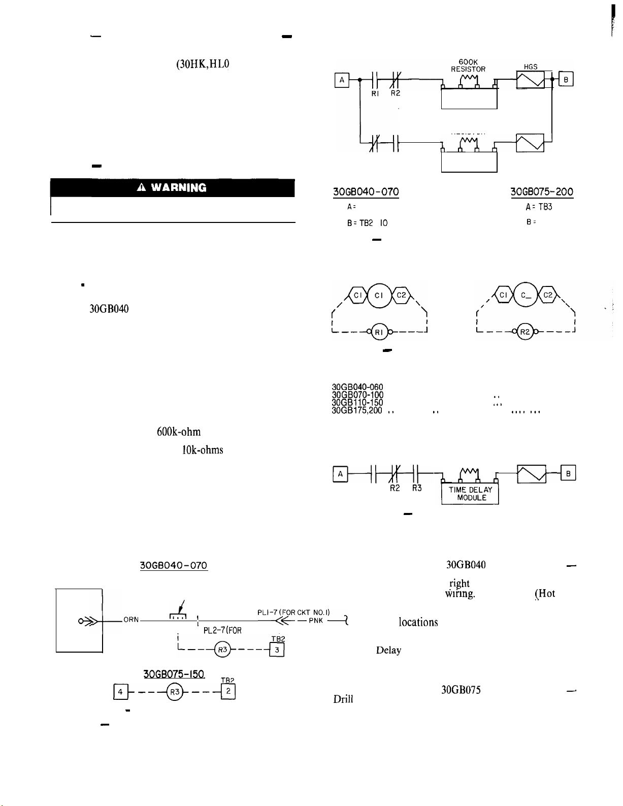
UNITS 30GB040 THROUGH 070 FLOTRONIC (See
Fig. 3.) - Control logic allows the hot gas bypass to be
energized only on the first stage of capacity.
A unit with 2 unloaders has the automatic lead/lag
feature which allows starting of either circuit, and
thus must have 2 hot gas bypass packages, one per circuit
(see Fig. 4).
On the 040-060 units, R3 should energize with compressor no. 2. On the 070 unit. R3 energizes with compressor no. 3. In both instances, it is the lead compressor
on circuit no. 2 (see Fig. 5.)
The time delay module must be set for a one-minute
delay by connecting a 600k-ohm resistor between the
center terminals of the module (see Fig. 6). (One second
of time delay results from each lOk-ohms of resistance.)
NOTES:
1. Relays R 1 and R2 apply to all units.
2. R3 applies only to units with a single unloader. Units
with no unloaders or 2 unloaders do not require R3.
3. 30GB 175 and 200 units do not use unloaders.
3OGB040-070 3066075-200
A= TB2 4
cl
B=TB2
IO
q
AzTB3
6:
TB2 2
Fig. 4 -Hot Gas Solenoid Wiring, Units with
No Unloaders or Two Unloaders
Fig. 5
Connect R2 in parallel with lead compressor in circuit 2:
30GB040-060
30GB070-100
30GBliO-150
30GB175,200 . ., . . . . . . . , . ., . . . . . . . . . . . . . . . . . ,. *. .
(Refer to Fig. 2 for compressor locations.)
RI and R2 Coil Wiring, All Units
-
. . . . . . . . . . . . . . . . . . . . . . . . . . . . . . . . . . . . . . . Comp 2
. . . . . . . . . . . . . . . . . , . . . . . . . . . . *. . . . . . . . . . Comp 3
. . . . . . . . . . . . . . . . . . . . . . . . . . . .
600K
RESISTOR
iwt
RI R2 R3
Fig. 6 - Hot
Single
Gas Solenoid Wiring,
Unloader Units
I +.
. . . . . . . . Comp 4
.,.
Comp 5
HGS
ell
I
cl
cl
~
I
30G6040-070
RELAY
BOARD
J6
e
PIN 4
4--
NOTE: 3063175,200 - R3 DOES NOT APPLY.
ORNr4,
30GB075-150
TB4 TE2
r--a--+J
FIELD SPLICE
I
,
PL2-7(FOR CKT NO.21
I
Fig. 3 -R3 Coil Wiring (R3 used only with
units having a single unloader)
PLI-‘(YR CKTF”,;.‘)
FLOTRONIC’” UNITS, 30GB040 THROUGH 070
Drill a hole to accommodate a standard conduit fitting
in bottom of control box at fight end, adjacent to existing
entrance hole for control wiring. Locate HGR
(,Hot
Gas
Bypass Relay) in right side of control box adjacent to
existing relays. Using the HGR base as a template, mark
mountmg hole locations and drill appropriate hole. Run
conduit from the bypass valve to the control box and wire
relays into control circuit as shown in Fig. 4. Relays
and Time DeIay Module should be installed in the upper
left corner of the control box, above the transformer.
FLOTRONIC UNITS, 30GB075 THROUGH 200
Driil 2 holes in the bottom right of the control box, next
to the compressor conduit holes, to accommodate stand-
ard conduit fittings. Run conduit from the bypass valve
to the control box and wire relays into control circuit
as shown in Fig. 4.
-
-
Page 4

ALL FLOTRONIC UNITS - Units require control
relays
tained
R) and Time Delay Module. They may be ob-
!
rom your Carrier distributor under the following
Carrier Part Numbers:
Rl and R2
R3
Time Delay Module
115-v
23Cbv
24-v
UNITS 30HK,HL015 THROUGH
HN61KK041 DPDT
HN61KK913 DPDT
HN61 KK040
30HK501602
DPDT
060 (Except 020,
60 Hz, and 0 15, 50 Hz.)
IMPORTANT: On 30HK,HL 2-compressor units,
the SEQUENCE switch on the control panel must
be in the l-2 position to obtain hot gas bypass
operation.
Run the conduit from the bypass valve to one of the
knockouts provided on the right side of the unit control
box. Connect the control wires as shown in Fig. 7.
UNITS
30GTO15
THROUGH 035 (except 020, 60 Hz,
and 015, 50 Hz) - Connect control wires as shown in
Fig. 8. At LLSV, connect to existing splice containing
white wire.
-j+------+g+----+J-
TB2
HGS
A. CONNECTIONS FOR SINGLE-COMPRESSOR UNITS
(60~~: 015,025,030;
-me--
,B.
CONNECTIONS FOR TWO-COMPRESSOR UNITS
(50 AND 60HZ:
See Combined Legend.
Fig. 7
-
040,050,060;
Hot Gas Bypass Field Wiring;
50~z:
------
HGS
020,025)
30HK,HL Units
TB2
-El--
TB2
50HZ: 0301
OPERATION AND ADJUSTMENT
The bypass valve is factory set to begin opening when
suction pressure drops to about 62 psig. This pressure
corresponds to a chllled water controller set point of
approximately 44 F. If the chilled water set point is lower
than 44 F, it will be necessary to decrease the bypass valve
setting for proper operation. Conversely, for
chllled
water
y;
set points above 44 F, the bypass valve setting must be
increased. A change in condensing temperature will also
require a change in bypass valve set point. As condensing
temperature decreases, decrease the bypass
vaIve
set
point until it opens at the desired conditions.
i,--------
See Combined Legend.
Refer to unit wiring label inside front access door for complete
wiring schematic.
Fig. 8
Hot Gas Bypass
-
COMBINED LEGEND
(Fig. 3 - 8)
FiGS 1
LLSV
TB
TC2
----
Compressor Contactor
Hot Gas Bypass Solenoid (Splice Conn)
Liquid Line Solenoid Valve
-
Terminal Block
-
-
Temperature Controller (X-in. Female Quick-Conn)
cl
Terminal on TB
0
Terminal on Control Component
Factory Wiring
Field Wiring
(#6
Ring Conn)
--e---t-
HGS
Fierd
Wiring; 30GT Units
(%-in.
Female Quick-Conn)
LLSV
i
Manufacturer reserves the right to discontinue, or change at any time, specifications or designs without notice and without incurring obligations.
Book 2
Tab 5c
-+
PC171
Catalog No. 533-039
Printed in U.S.A. Form 30G,H-1
S1
PC4
4
2-89 Replaces: 30GB,WlSI
 Loading...