

Page 1

25SCA5
Comfort™ Series Single-Stage Heat Pump
with Puron® Refrigerant
1-1/2 To 5 Tons
Product Data
This unit has been designed utilizing Carrier’s non-ozone depleting
Puron® refrigerant. Heat pumps with Puron® refrigerant provide a
collection of features unmatched by any other family of equipment.
NOTE: Ratings contained in this document are subject to change at any
time. Always refer to the AHRI directory (www.ahridirectory.org) for
the most up-to-date ratings information.
Industry leading
Features / Benefits
Efficiency
• 14.3 - 15.2 SEER2 / 11.0 - 12.5 EER2 / 7.5 - 8.1 HSPF2
(depending on unit size and indoor combination installed)
• Microtube technology refrigeration system
• Indoor air quality accessories available
Sound
• Sound levels as low as 69 dBA with accessory sound blanket
Comfort
• System supports programmable or standard thermostat controls
Reliability
• Non-ozone depleting Puron® refrigerant
• Scroll compressor
• Internal pressure relief valve
• Internal thermal overload
• Loss of charge switch
• Filter drier
• Balanced refrigeration system for maximum reliability
Durability
WeatherArmor™ Protection Package:
• Solid, durable sheet metal construction
• Dense wire coil guard
Applications
• Long-line - up to 250 feet (76.20 m) total equivalent length, up to 200
feet (60.96 m) condenser above evaporator, or up to 80 ft. (24.38 m)
evaporator above condenser (See Longline Guide for more
information.)
• Low ambient cooling (down to 0°F/-17.8°C) with approved low
ambient accessory kits
Page 2
25SCA5: Product Data
Model Number Nomenclature
1 2 3 4 5 6 7,8 9 10 11 12
N N A A A/N N N A/N A/N A/N N
2 5 S C A 5 18 A 0 0 3
Refrigerant and
OD Type
25 = R-410A HP S = Single Stage C=Comfort A = Initial Series
OD Design Type Tier
Major
Series
SEER2
5=14.3
SEER2
Nominal Cooling
Capacity
18 = 18,000 BTUH (1.5 Tons) 24 = 24,000 BTUH (2 Tons) 30 = 30,000 BTUH (2.5 Tons) 36 = 36,000 BTUH (3 Tons) 42 = 42,000 BTUH (3.5 Tons) 48 = 48,000 BTUH (4 Tons) 60 = 60,000 BTUH (5 Tons)
Region Feature
A=Standard HP 0=Standard 0=Standard
Special
Feature
Tested AHRI Combination Ratings
NOTE: Ratings contained in this document are subject to change at any time.
For AHRI ratings certificates, please refer to the AHRI directory www.ahridirectory.org
Additional ratings and system combinations can be accessed via the Ratings Database here: www.MyCarrierRatings.com
Voltage
3=208-230-1
or 208/230-1
CATALOG ORDERING NUMBERS
Size Model Number
18 25SCA518A003
24 25SCA524A003
30 25SCA530A003
36 25SCA536A003
42 25SCA542A003
48 25SCA548A003
60 25SCA560A003
Standard Features
Feature 18 24 30 36 42 48 60
Puron Refrigerant
Scroll Compressor X X X X X X X
Field Installed Filter Drier X X X X X X X
Front Seating Service Valves X X X X X X X
Internal Pressure Relief Valve X X X X X X X
Internal Thermal Overload X X X X X X X
Long Line capability X X X X X X X
Low Ambient capability with Kit X X X X X X X
Suction Line Accumulator X X X X X X X
Loss of Charge Switch X X X X X X X
X = Standard
X X X X X X X
Manufacturer reserves the right to change, at any time, specifications and designs without notice and without obligations.
2
Page 3
25SCA5: Product Data
Physical Data
Unit Size 18 24 30 36 42 48 60
Compressor Type Scroll
Refrigerant Puron® (R-410A)
Control TXV (Puron® Hard Shutoff) Charge (lb) 5.9 6.3 9.0 9.0 9.9 10.8 13.7 Outdoor Htg. Piston # 42 46 52 57 61 65 76 Cond Fan Forward Swept or Propeller Type, Direct Drive Air Discharge Vertical
Air Qty (CFM) 2346 2652 2652 3550 3716 3716 4779 Motor HP 1/12 1/10 1/10 1/4 1/4 1/4 1/4 Motor RPM 800 825 825 825 1110 1110 825
Cond Coil
Face Area (Sq ft) 15.0 17.2 15.0 15.0 17.2 19.3 25.1 Fins per In. 20 20 20 20 20 20 20 Rows 1 1 2 2 2 2 2 Circuits 6 6 7 7 10 12 12
Valve Connect (In. ID)
Vapor 5/8 5/8 3/4 3/4 7/8 7/8 7/8 Liquid 3/8"
Refrigerant Tubes
Rated Vapor†
(0-80 Ft Tube Length)
Rated Liquid Line
*. For 15 ft. lineset
†. Units are rated with 25 ft (7.6 m) of lineset length. See Vapor Line Sizing and Cooling Capacity Loss table when using other sizes and lengths of lineset.
‡. See Liquid Line Sizing For Cooling Only Systems with Puron Refrigerant tables.
Note: See unit Installation Instruction for proper installation.
*
(In. OD)
‡
(0-80 Ft Tube Length)
5/8 5/8 3/4 3/4 7/8 7/8 1 1/8
3/8"
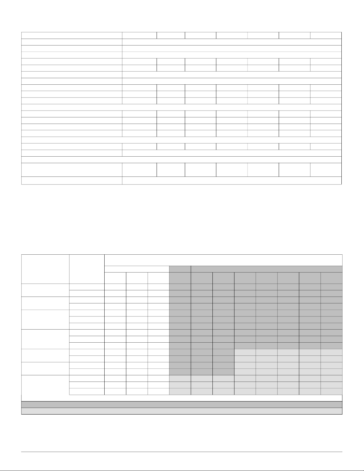
Vapor Line Sizing and Cooling Capacity Loss
Acceptable vapor line diameters provide adequate oil return to the compressor while avoiding excessive capacity loss. The suction line diameters
shown in the chart below are acceptable for HP systems with Puron® refrigerant:
Vapor Line Sizing and Cooling Capacity Losses - Puron® Refrigerant 1- Stage Heat Pump Applications
Unit Nominal Size
(Btuh)
18,000
24,000
30,000
36,000
42,000
48,000
60,000
Standard Length = 80 ft. (24.4 m) or less total equivalent length
Applications in this area are long line. Accessories are required as shown recommended on Long Line Application Guidelines
Applications in this area may have height restrictions that limit allowable total equivalent length, when outdoor unit is below indoor unit See Long Line Application Guidelines
Acceptable
Vapor Line
Diameters (In.
OD)
1/2 1 2 3
5/8 0 0 1
5/8 0 1 1
3/4 0 0 0
5/8 1 2 3
3/4 0 0 1
7/8 0 0 0
5/8 1 2 4
3/4 0 0 1
7/8 0 0 0
3/4 0 1 2
7/8 0 0 1
3/4 0 1 2
7/8 0 0 1
3/4 1 2 4
7/8 0 1 2
1 1/8 0 0 0
Standard Application
25
(7.62)50(15.2)80(24.4)
80+
(24.4+)
3 4 6 7 8 9 10 12
1 1 1 2 2 3 3 3
1 2 3 3 4 4 5 6
0 0 1 1 1 1 1 2
3 3 4 5 6 7 8 9
1 1 1 2 2 2 3 3
0 0 1 1 1 1 1 1
4 5 6 7 9 10 11 13
1 1 2 2 3 3 4 4
0 0 1 1 1 1 2 2
2 2 3 4 4 5 6 6
1 1 1 2 2 2 3 3
2 3 4 5 5 6 7 8
1 1 2 2 2 3 3 4
4 5 6 7 9 10 11 12
2 2 3 4 4 5 5 6
0 1 1 1 1 1 1 2
Cooling Capacity Loss (%)
Total Equivalent Line Length (ft)
Long Line Application Requires A ccessories
100
(30.48)
125
(38.10)
150
(45.72)
175
(53.34)
200
(60.96)
(68.58)
225
250
(76.20)
Manufacturer reserves the right to change, at any time, specifications and designs without notice and without obligations.
3
Page 4

25SCA5: Product Data
Refrigerant Piping Length Limitations
Maximum Line Lengths:
The maximum allowable total equivalent length for heat pumps varies depending on the vertical separation. See the tables below for allowable lengths
depending on whether the outdoor unit is on the same level, above or below the outdoor unit.
Maximum Line Lengths for Heat Pump Applications
MAXIMUM ACTUAL LENGTH
Units on equal level 200 (61) 250 (76.2) N/A
Outdoor unit ABOVE
indoor unit
Outdoor unit BELOW
indoor unit
*.* Maximum actual length not to exceed 200 ft (61 m)
ft (m)
200 (61) 250 (76.2) 200 (61)
*
See Table ’Maximum Total Equivalent Length: Outdoor Unit BELOW Indoor Unit’
MAXIMUM EQUIVALENT LENGTH{
ft (m)
MAXIMUM VERTICAL SEPARATION
ft (m)
Maximum Total Equivalent Length*{ - Outdoor Unit BELOW Indoor Unit
Puron® Refrigerant - Maximum Total Equivalent Length
21-30
HP with
Vertical Separation ft (m) Outdoor unit BELOW indoor unit;
31-40
(9.4 - 12.2)
41-50
(12.5 - 15.2)
51-60
(15.5 - 18.3)
61-70
(18.6 - 21.3)
71-80
(21.6 - 24.4)
Size
18,000 3/8 250* 250* 250* 250* 250* 250* 250*
24,000 3/8 250* 250* 250* 250* 250* 250* 250*
30,000 3/8 250* 250* 250* 250* 250* 250* 250*
36,000 3/8 250* 250* 250* 250* 250* 250* 250*
42,000 3/8 250* 250* 250* 250* 250* 250* 150
48,000 3/8 250* 250* 250* 250* 230 160 —
60,000 3/8 250* 225* 190 150 110 — —
*.Total equivalent length accounts for losses due to elbows or fitting. See the Long Line Guideline for details.
— = outside acceptable range
Liquid Line
Diameter
w/ TXV
0-20
(0 - 6.1)
(6.4 - 9.1)
Long Line Applications
An application is considered Long Line when the refrigerant level in the system requires the use of accessories to maintain acceptable refrigerant
management for systems reliability. Defining a system as long line depends on the liquid line diameter, actual length of the tubing, and vertical
separation between the indoor and outdoor units.
For Heat Pump systems, the chart below shows when an application is considered Long Line. Beyond these lengths, long line accessories are
required:
HP with Puron® Refrigerant Long Line Description ft (m)
Beyond these lengths, long line accessories are required
Liquid Line Size Units On Same Level Outdoor Below Indoor Outdoor Above Indoor
3/8 80 (24.4) 20 (6.1) vertical or 80 (24.4) total 80 (24.4)
Note: See Long Line Guideline for details
Manufacturer reserves the right to change, at any time, specifications and designs without notice and without obligations.
4
Page 5

25SCA5: Product Data
Accessories
KIT NUMBER KIT NAME 18 24 30 36 42 48 60
KAACH1701AAA Crankcase Heater X X X X
KAACH1601AAA Crankcase Heater X X S
KAATD0101TDR Time Delay Relay X X X X X X X
KHAIR0201AAA Isolation Relay X X X X X X X
KHALS0401LLS Solenoid Valve Kit X X X X X X X
KHASS0606MPK Snow Stand X X X X X X X
KSACY0101AAA Cycle Protector X X X X X X X
KSAFT0101AAA Evaporator Freeze Stat X X X X X X X
KSAHI0401PUR High Pressure Switch Kit X X X X X X X
KSAHS2501AAA Hard Start X X X X X X X
KSALA0301410 Low Ambient Cooling Pressure Switch X X X X X X X
KSALA1001AAA MotorMaster X X X X X X X
KSATX0201PUR TXV Kit X X X
KSATX0301PUR TXV Kit X X
KSATX0401PUR TXV Kit X X
KSBTX0201PUR TXV Kit X X X
KSBTX0301PUR TXV Kit X X
KSBTX0401PUR TXV Kit X X
KSASH2301COP Sound Blanket X X X X
KSASH2401COP Sound Blanket X X X
KSASF0201AAA Support Feet X X X X X X X
X = Accessory
S = Standard
Manufacturer reserves the right to change, at any time, specifications and designs without notice and without obligations.
5
Page 6

25SCA5: Product Data
Accessory Usage Guideline
Accessory
Accumulator Standard Standard Standard
Ball Bearing Fan Motor Standard Standard Standard
Compressor Start Assist Capacitor and
Relay
Crankcase Heater
Evaporator Freeze Thermostat Yes No No
Hard Shutoff TXV Yes Yes No
Isolation Relay Yes No No
Liquid Line Solenoid Valve No
Motor Master® Control or
Low Ambient Switch
Support Feet Recommended No Recommended
*. For tubing line sets between 80 and 200 ft. (24.38 and 60.96 m) and/or 20 ft. (6.09 m) vertical differential, refer to Residential Split-System Longline Application Guideline.
†. Standard on 3 phase units only
REQUIRED FOR LOW-AMBIENT
COOLING APPLICATIONS
(Below 55°F / 12.8°C)
Yes Yes No
†
Yes
Yes No No
See Long-Line Application Guideline
REQUIRED FOR
LONG LINE APPLICATIONS
Yew No
*
Accessory Description and Usage (Listed Alphabetically)
1. Ball-Bearing Fan Motor
A fan motor with ball bearings which permits speed reduction while
maintaining bearing lubrication.
Usage Guideline:
Required on all units when MotorMasterr is used.
2. Compressor Start Assist - Capacitor and Relay
Start capacitor and relay gives a ”hard” boost to compressor motor at
each start up.
Usage Guideline:
Required for single-phase scroll compressors in the following
applications:
Long line
Low ambient cooling
Suggested for all compressors in areas with a history of low voltage
problems.
3. Crankcase Heater
An electric resistance heater which mounts to the base of the compressor
to keep the lubricant warm during off cycles. Improves compressor
lubrication on restart and minimizes the chance of liquid slugging.
Usage Guideline:
Required in low ambient cooling applications.
Required in long line applications.
Suggested in all commercial applications.
4. Cycle Protector
The cycle protector is designed to prevent compressor short cycling.
This control provides an approximate 5-minute delay after power to the
compressor has been interrupted for any reason, including power outage,
protector control trip, thermostat jiggling, or normal cycling.
5. Evaporator Freeze Thermostat
An SPST temperature-actuated switch that stops unit operation when
evaporator reaches freeze-up conditions.
Usage Guideline:
Required when low ambient kit has been added.
6. Low-Ambient Pressure Switch Kit
A long life pressure switch which is mounted to outdoor unit service
valve. It is designed to cycle the outdoor fan motor in order to maintain
head pressure within normal operating limits (approximately 100 psig to
225 psig). The control will maintain working head pressure at
low-ambient temperatures down to 0_F (-18_C) when properly installed
and also using wind baffles. Instructions provided in accessory kit.
Usage Guideline:
A Low-Ambient Pressure Switch or MotorMasterr Low-Ambient
Controller must be used when cooling operation is used at outdoor
temperatures below 55_F (12.8_C).
7. MotorMasterr Low-Ambient Controller
A fan-speed control device activated by a temperature sensor, designed
to control condenser fan motor speed in response to the saturated,
condensing temperature during operation in cooling mode only. For
outdoor temperatures down to 0°F/–17.8°C), it maintains condensing
temperature at 100_F ±10_F (37.8_C ±5.5_C).
Usage Guideline:
A MotorMasterr Low Ambient Controller or Low-Ambient
Pressure Switch must be used when cooling operation is used at
outdoor temperatures below 55_F (12.8_C).
Suggested for all commercial applications.
8. Outdoor Air Temperature Sensor
This device enables the thermostat to display the outdoor temperature.
This device is also required to enable special thermostat features such as
auxiliary heat lock out.
Usage Guideline:
Suggested for use with compatible Carrier thermostats.
9. Sound Hood
Wraparound sound reducing cover for the compressor. Reduces the
sound level of the compressor.
Usage Guideline:
Suggested when unit is installed closer than 15 ft (4.57 m) to quiet
areas, bedrooms, etc.
Suggested when unit is installed between two houses less than
10 ft (3 m) apart.
REQUIRED FOR
SEA COAST APPLICATIONS
(Within 2 miles / 3.22 km)
No
Manufacturer reserves the right to change, at any time, specifications and designs without notice and without obligations.
6
Page 7

25SCA5: Product Data
Accessory Description and Usage (Listed Alphabetically) Continued
10. Support Feet
Four or five stick-on plastic feet that raise the unit 4 in. (101.6 mm)
above the mounting pad. This allows sand, dirt, and other debris to be
flushed from the unit base, minimizing corrosion.
Usage Guideline:
Suggested in the following applications:
Coastal installations.
Windy areas or where debris is normally circulating.
Rooftop installations.
For improved sound ratings.
11. Thermostatic Expansion Valve (TXV)
A modulating flow-control valve which meters refrigerant liquid flow
rate into the evaporator in response to the superheat of the refrigerant gas
leaving the evaporator.
Kit includes valve, adapter tubes, and external equalizer tube. Hard shut
off types are available.
Usage Guideline:
Required to achieve AHRI ratings in certain equipment
combinations. Refer to combination ratings.
Hard shut off TXV or LLS required in air conditioner long line
applications.
Required for use on all zoning systems.
12. Time-Delay Relay
An SPST delay relay which briefly continues operation of indoor blower
motor to provide additional cooling after the compressor cycles off.
NOTE: Most indoor unit controls include this feature. For those that do
not, use the guideline below.
Usage Guideline:
For improved efficiency ratings for certain combinations of indoor
and outdoor units. Refer to AHRI Directory of Certified Product
Performance (AHRI Directory).
When a Time-Delay Relay (TDR) is called for in the AHRI Directory,
use a 30 second TDR for MicroChannel Indoor units and use a 90
second TDR for Round Tube Plate Fin Indoor units.
13. Winter Start Control
This control is designed to alleviate nuisance opening of the
low-pressure switch by bypassing it for the first 3 minutes of operation.
Manufacturer reserves the right to change, at any time, specifications and designs without notice and without obligations.
7
Page 8

25SCA5: Product Data
Electrical Data
UNIT SIZE V/PH
OPER VOLTS
MAX MIN LRA RLA FLA
18
24 59.5 11.1 0.60 14.5 25
30 67.9 14.1 0.60 18.2 30
36 83.1 15.3 1.20 20.3 30
208-230-1 253 197
42 110.0 18.6 1.40 24.7 40
48 120.0 25.0 1.52 32.8 50
60 150.0 25.6 1.20 33.2 50
*. Perrmissible limits of the voltage range at which the unit will operate satisfactorily
†. Time-Delay fuse.
FLA—Full Load Amps
LRA—Locked Rotor Amps
MCA—Minimum Circuit Amps
RLA—Rated Load Amps
NOTE: Control circuit is 24-V on all units and requires external power source. Copper wire must be used from service disconnect to unit.
All motors/compressors contain internal overload protection.
Complies with requirements of ASHRAE Standards 90.1
Short Circuit Current Rating (SCCR): 5kA rms
*
COMPR FAN
MCA
45.7 10.3 0.50 13.4 20
Sound Power Level Without Sound Hood
STANDARD
UNIT SIZE
RATING
(dBA)
125 250 500 1000 2000 4000 8000
18 71 70.2 66.4 65.1 67.4 62.8 58.2 52.5
24 76 66.3 68.4 69.4 67.7 64.4 61.4 55.9
30 76 70.1 71.3 70.8 69.6 64.0 60.6 54.9
36 76 74.0 72.5 71.7 70.5 66.1 61.7 55.6
42 76 72.1 72.6 70.0 67.6 62.9 60.5 56.0
48 76 75.5 72.4 71.4 68.3 63.1 60.5 55.5
60 76 65.2 67.0 67.4 70.0 62.6 59.7 55.5
NOTE: Tested in compliance with AHRI 270 but not listed with AHRI.
TYPICAL OCTAVE BAND SPECTRUM (dB, without tone adjustment)
MAX FUSE
CKT BRK
AMPS
†
or
Sound Power Level With Sound Hood
STANDARD
UNIT SIZE
RATING
(dBA)
125 250 500 1000 2000 4000 8000
18 69 70.6 66.2 64.8 65.7 61.2 57.5 51.3
24 74 66.7 68.1 68.7 66.5 63.1 60.0 53.1
30 74 71.4 70.5 70.5 68.3 63.4 60.3 53.5
36 74 74.7 72.7 71.8 68.6 64.3 59.0 51.6
42 74 72.8 73.7 70.3 67.3 62.6 59.8 53.4
48 74 76.3 71.9 71.0 68.1 62.9 60.0 53.9
60 73 65.4 67.5 67.5 68.8 61.5 58.5 52.9
NOTE: Tested in compliance with AHRI 270 but not listed with AHRI.
TYPICAL OCTAVE BAND SPECTRUM (dB, without tone adjustment)
Charging Subcooling (TXV-Type Expansion Device)
UNIT SIZE-VOLTAGE REQUIRED SUBCOOLING °F (°C)
18 7 (3.9)
24 7 (3.9)
30 12 (6.7)
36 12 (6.7)
42 10 (5.6)
48 13 (7.2)
60 10 (5.6)
HP Only Replacement with Piston Indoors
This heat pump may only be installed with piston metered indoor units as replacement components in a piston system.
When installing a non-rated heat pump with a piston indoor unit, the correct piston must be installed, which should be listed in the indoor unit
Installation Instructions or Product Data.
Replacement pistons can be ordered from Replacement Components (RC).
Manufacturer reserves the right to change, at any time, specifications and designs without notice and without obligations.
8
Page 9

Dimensions
Manufacturer reserves the right to change, at any time, specifications and designs without notice and without obligations.
9
25SCA5: Product Data
Page 10

Clearances
Clearances (various examples)
Wall
Wall
Wall
Wall
24”
Service
6”
(152.4 mm)
24”
(609.6)
Service
24”
(609.6)
Service
24”
(609.6)
Service
24”
(609.6)
Service
12”
(304.8)
12”
(304.8)
12”
(304.8)
12”
(304.8)
6”
(152.4)
Note: Numbers in ( ) = mm
Allow 48” above unit
18”
(457.2)
18”
(457.2)
18”
(457.2)
Manufacturer reserves the right to change, at any time, specifications and designs without notice and without obligations.
25SCA5: Product Data
10
IMPORTANT: When installing multiple units in an alcove, roof well, or partially enclosed area, ensure there is adequate ventilation to prevent re-circulation of discharge air.
Page 11

Balance Point Worksheet
Manufacturer reserves the right to change, at any time, specifications and designs without notice and without obligations.
11
25SCA5: Product Data
Page 12

DETAILED COOLING CAPACITIES#
EVAPORATOR AIR
CFM EWB
Manufacturer reserves the right to change, at any time, specifications and designs without notice and without obligations.
72.0 (22.2) 20.65 10.58 1.15 19.67 10.21 1.30 18.65 9.83 1.47 17.57 9.44 1.65 16.37 9.00 1.87 15.06 8.54 2.11
67.0 (19.4) 18.74 13.02 1.17 17.84 12.65 1.31 16.91 12.27 1.48 15.92 11.87 1.66 14.84 11.44 1.88 13.64 10.96 2.12
525
63.0 (17.2)†† 17.37 12.52 1.18 16.52 12.15 1.32 15.66 11.77 1.48 14.74 11.37 1.67 13.74 10.93 1.88 12.63 10.45 2.12
62.0 (16.7) 17.07 15.40 1.18 16.26 15.01 1.32 15.44 14.60 1.49 14.58 14.14 1.67 13.76 13.32 1.88 12.79 12.79 2.12
57.0 (13.9) 16.50 16.50 1.18 15.86 15.86 1.32 15.19 15.19 1.49 14.47 14.47 1.67 13.67 13.67 1.88 12.77 12.77 2.12
72.0 (22.2) 21.04 11.10 1.17 20.03 10.73 1.32 18.96 10.35 1.48 17.83 9.94 1.67 16.59 9.50 1.89 15.23 9.03 2.13
67.0 (19.4) 19.10 13.87 1.18 18.17 13.49 1.33 17.20 13.10 1.50 16.17 12.69 1.68 15.05 12.24 1.90 13.81 11.75 2.14
600
63.0 (17.2)†† 17.71 13.31 1.19 16.84 12.93 1.34 15.94 12.54 1.50 14.99 12.13 1.69 13.95 11.68 1.90 12.80 11.18 2.14
62.0 (16.7) 17.47 16.50 1.19 16.65 16.06 1.34 15.88 15.44 1.50 15.04 15.04 1.69 14.18 14.18 1.90 13.22 13.22 2.14
57.0 (13.9) 17.19 17.19 1.20 16.50 16.50 1.34 15.79 15.79 1.50 15.02 15.02 1.69 14.16 14.16 1.90 13.20 13.20 2.14
72.0 (22.2) 21.34 11.60 1.19 20.29 11.22 1.34 19.19 10.84 1.50 18.02 10.43 1.69 16.74 9.98 1.91 15.35 9.50 2.15
67.0 (19.4) 19.38 14.68 1.20 18.41 14.29 1.35 17.42 13.89 1.51 16.35 13.47 1.70 15.20 13.00 1.92 13.95 12.48 2.16
675
63.0 (17.2)†† 17.98 14.06 1.21 17.06 13.66 1.36 16.16 13.27 1.52 15.17 12.84 1.71 14.10 12.38 1.92 12.93 11.85 2.16
62.0 (16.7) 18.01 16.88 1.21 17.22 16.30 1.36 16.30 16.30 1.52 15.48 15.48 1.71 14.58 14.58 1.92 13.56 13.56 2.16
57.0 (13.9) 17.76 17.76 1.21 17.03 17.03 1.36 16.28 16.28 1.52 15.46 15.46 1.71 14.56 14.56 1.92 13.55 13.55 2.16
72.0 (22.2) 28.31 14.39 1.54 27.03 13.91 1.72 25.65 13.40 1.93 24.16 12.86 2.16 22.53 12.28 2.43 20.76 11.66 2.74
67.0 (19.4) 25.74 17.76 1.55 24.54 17.27 1.74 23.27 16.75 1.95 21.90 16.19 2.19 20.41 15.60 2.46 18.77 14.95 2.77
700
63.0 (17.2)†† 23.88 17.09 1.56 22.77 16.59 1.75 21.58 16.07 1.96 20.29 15.51 2.20 18.89 14.91 2.48 17.36 14.25 2.79
62.0 (16.7) 23.47 21.02 1.56 22.40 20.51 1.75 21.26 19.94 1.96 20.04 19.31 2.20 18.80 18.80 2.48 17.57 17.57 2.79
57.0 (13.9) 22.69 22.69 1.57 21.83 21.83 1.75 20.91 20.91 1.96 19.89 19.89 2.20 18.78 18.78 2.48 17.54 17.54 2.79
72.0 (22.2) 28.73 14.96 1.56 27.41 14.48 1.74 25.98 13.96 1.95 24.45 13.41 2.18 22.77 12.82 2.45 20.96 12.19 2.75
12
780
67.0 (19.4) 26.13 18.68 1.57 24.89 18.18 1.76 23.60 17.66 1.97 22.18 17.09 2.20 20.63 16.47 2.48 18.98 15.82 2.79
63.0 (17.2)†† 24.27 17.95 1.58 23.11 17.44 1.77 21.88 16.91 1.98 20.56 16.34 2.22 19.12 15.72 2.50 17.55 15.05 2.81
62.0 (16.7) 23.91 22.23 1.58 22.82 21.67 1.77 21.67 21.67 1.98 20.65 19.77 2.22 19.35 19.35 2.49 18.05 18.05 2.80
57.0 (13.9) 23.45 23.45 1.59 22.54 22.54 1.77 21.57 21.57 1.98 20.50 20.50 2.22 19.33 19.33 2.49 18.03 18.03 2.80
72.0 (22.2) 29.21 15.76 1.59 27.84 15.27 1.77 26.36 14.75 1.98 24.76 14.20 2.21 23.03 13.60 2.48 21.16 12.96 2.78
67.0 (19.4) 26.57 19.99 1.60 25.30 19.49 1.79 23.96 18.95 2.00 22.50 18.36 2.23 20.90 17.72 2.50 19.21 17.03 2.81
900
63.0 (17.2)†† 24.75 19.19 1.61 23.51 18.65 1.80 22.24 18.11 2.01 20.86 17.51 2.25 19.38 16.87 2.53 17.78 16.16 2.84
62.0 (16.7) 24.74 23.06 1.61 23.45 23.45 1.80 22.77 20.71 2.01 21.27 21.27 2.25 20.02 20.02 2.52 18.65 18.65 2.82
57.0 (13.9) 24.39 24.39 1.62 23.42 23.42 1.80 22.38 22.38 2.01 21.24 21.24 2.25 20.00 20.00 2.52 18.63 18.63 2.82
72.0 (22.2) 33.73 17.56 1.88 32.26 17.00 2.08 30.69 16.41 2.32 29.01 15.78 2.59 27.19 15.11 2.89 25.19 14.39 3.24
67.0 (19.4) 30.54 21.64 1.87 29.19 21.08 2.08 27.76 20.48 2.31 26.23 19.85 2.58 24.56 19.18 2.88 22.74 18.43 3.23
875
63.0 (17.2)†† 28.25 20.78 1.87 26.96 20.19 2.08 25.66 19.61 2.31 24.23 18.98 2.57 22.69 18.30 2.88 20.98 17.55 3.22
62.0 (16.7) 27.76 25.61 1.87 26.55 25.01 2.08 25.30 24.37 2.31 23.96 23.64 2.57 22.77 22.23 2.88 21.24 21.24 3.22
57.0 (13.9) 26.90 26.90 1.87 25.95 25.95 2.08 24.92 24.92 2.31 23.81 23.81 2.57 22.58 22.58 2.88 21.21 21.21 3.22
72.0 (22.2) 34.62 18.81 1.93 33.05 18.23 2.14 31.39 17.63 2.37 29.62 16.98 2.64 27.70 16.29 2.95 25.60 15.55 3.29
67.0 (19.4) 31.35 23.69 1.93 29.91 23.07 2.13 28.40 22.47 2.37 26.81 21.82 2.63 25.06 21.10 2.94 23.16 20.32 3.28
1055
63.0 (17.2)†† 29.00 22.65 1.93 27.67 22.06 2.13 26.27 21.44 2.36 24.77 20.79 2.63 23.06 20.18 2.93 21.39 19.27 3.27
62.0 (16.7) 28.70 28.17 1.93 27.79 26.62 2.13 26.32 26.32 2.36 25.10 25.10 2.63 23.75 23.75 2.93 22.25 22.25 3.28
57.0 (13.9) 28.47 28.47 1.93 27.41 27.41 2.13 26.29 26.29 2.36 25.06 25.06 2.63 23.72 23.72 2.93 22.22 22.22 3.28
72.0 (22.2) 34.88 19.27 1.95 33.28 18.68 2.16 31.59 18.07 2.39 29.79 17.42 2.66 27.84 16.73 2.97 25.71 15.98 3.31
67.0 (19.4) 31.58 24.42 1.95 30.13 23.81 2.15 28.60 23.18 2.39 26.97 22.55 2.65 25.21 21.79 2.96 23.29 21.01 3.30
1125
63.0 (17.2)†† 29.23 23.34 1.95 27.88 22.75 2.15 26.45 22.12 2.38 24.93 21.47 2.65 23.29 20.72 2.95 21.51 19.90 3.30
62.0 (16.7) 29.35 28.17 1.95 28.20 27.21 2.15 26.76 26.76 2.38 25.50 25.50 2.65 24.11 24.11 2.95 22.57 22.57 3.30
57.0 (13.9) 28.98 28.98 1.95 27.89 27.89 2.15 26.73 26.73 2.38 25.47 25.47 2.65 24.08 24.08 2.95 22.55 22.55 3.30
75.0 (23.9) 85.0 (29.4) 95.0 (35.0) 105.0 (40.6) 115.0 (46.1) 125.0 (51.7)
Capacity MBtuh Total Sys.
Total Sens‡ Total Sens‡ Total Sens‡ Total Sens‡ Total Sens‡ Total Sens‡
KW**
Capacity MBtuh Total Sys.
KW**
25SCA518A003 Outdoor Section With FJ4DNXA18L* Indoor Section
25SCA524A003 Outdoor Section With FJ4DNXB24L* Indoor Section
25SCA530A003 Outdoor Section With FJ4DNXB30L* Indoor Section
CONDENSER ENTERING AIR TEMPERATURES °F (°C)
Capacity MBtuh Total Sys.
KW**
Capacity MBtuh Total Sys.
KW**
Capacity MBtuh Total Sys.
KW**
25SCA5: Product Data
Capacity MBtuh Total Sys.
KW**
Page 13

DETAILED COOLING CAPACITIES# (Continued)
EVAPORATOR AIR
CFM EWB
Manufacturer reserves the right to change, at any time, specifications and designs without notice and without obligations.
72.0 (22.2) 41.65 21.37 2.29 39.73 20.65 2.56 37.70 19.88 2.81 35.53 19.08 3.10 33.22 18.24 3.46 30.74 17.34 3.94
67.0 (19.4) 37.84 26.35 2.33 36.07 25.61 2.59 34.20 24.83 2.85 32.20 24.01 3.14 30.07 23.15 3.49 27.78 22.23 3.97
1060
63.0 (17.2)†† 35.05 25.33 2.34 33.41 24.59 2.61 31.65 23.80 2.87 29.77 22.97 3.15 27.75 22.05 3.50 25.63 21.17 3.96
62.0 (16.7) 34.43 31.15 2.34 32.85 30.37 2.61 31.16 29.52 2.87 29.40 28.59 3.15 27.78 26.91 3.50 25.87 25.87 3.96
57.0 (13.9) 33.21 33.21 2.34 31.95 31.95 2.61 30.59 30.59 2.87 29.12 29.12 3.15 27.54 27.54 3.50 25.83 25.83 3.96
72.0 (22.2) 42.35 22.32 2.33 40.36 21.58 2.59 38.26 20.80 2.84 36.01 19.99 3.13 33.63 19.14 3.50 31.06 18.23 3.98
67.0 (19.4) 38.52 27.88 2.36 36.73 27.17 2.63 34.73 26.33 2.89 32.65 25.53 3.17 30.46 24.62 3.53 28.11 23.67 4.01
1200
63.0 (17.2)†† 35.69 26.76 2.38 33.97 25.98 2.65 32.15 25.22 2.91 30.21 24.37 3.19 28.15 23.46 3.54 25.95 22.50 4.01
62.0 (16.7) 35.17 33.16 2.38 33.55 32.30 2.65 31.96 31.04 2.91 30.19 30.19 3.19 28.50 28.50 3.54 26.68 26.68 4.01
57.0 (13.9) 34.46 34.46 2.38 33.13 33.13 2.65 31.69 31.69 2.91 30.14 30.14 3.19 28.46 28.46 3.54 26.65 26.65 4.01
72.0 (22.2) 42.92 23.27 2.36 40.87 22.52 2.62 38.70 21.74 2.88 36.39 20.92 3.17 33.94 20.05 3.54 31.31 19.13 4.02
67.0 (19.4) 39.04 29.46 2.41 37.15 28.70 2.67 35.15 27.89 2.93 33.03 27.01 3.22 30.77 26.12 3.58 28.38 25.12 4.05
1350
63.0 (17.2)†† 36.22 28.22 2.42 34.43 27.45 2.69 32.38 26.55 2.95 30.58 25.76 3.23 28.47 24.83 3.59 26.23 23.82 4.06
62.0 (16.7) 35.86 35.05 2.42 34.24 34.24 2.69 32.73 32.73 2.95 31.07 31.07 3.23 29.31 29.31 3.59 27.40 27.40 4.06
57.0 (13.9) 35.60 35.60 2.43 34.18 34.18 2.69 32.67 32.67 2.95 31.03 31.03 3.23 29.28 29.28 3.59 27.37 27.37 4.06
72.0 (22.2) 48.60 25.34 2.78 46.33 24.47 3.05 43.92 23.55 3.35 41.35 22.59 3.69 38.56 21.56 4.08 35.57 20.47 4.51
67.0 (19.4) 44.20 31.29 2.76 42.16 30.41 3.03 40.00 29.52 3.33 37.66 28.55 3.68 35.14 27.51 4.06 32.42 26.39 4.50
1240
63.0 (17.2)†† 41.02 30.12 2.75 39.13 29.25 3.02 37.13 28.33 3.32 34.97 27.38 3.66 32.64 26.34 4.05 30.10 25.20 4.49
62.0 (16.7) 40.34 37.05 2.75 38.51 36.14 3.02 36.60 35.16 3.32 34.57 34.05 3.66 32.61 32.17 4.05 30.38 30.38 4.49
57.0 (13.9) 38.95 38.95 2.74 37.50 37.50 3.01 35.95 35.95 3.32 34.26 34.26 3.66 32.39 32.39 4.05 30.33 30.33 4.49
72.0 (22.2) 49.37 26.42 2.83 47.01 25.53 3.10 44.51 24.60 3.40 41.83 23.62 3.74 38.96 22.57 4.13 35.87 21.47 4.56
13
1400
67.0 (19.4) 44.94 33.07 2.81 42.80 32.18 3.08 40.60 31.27 3.38 38.15 30.26 3.73 35.54 29.19 4.11 32.74 28.03 4.55
63.0 (17.2)†† 41.72 31.77 2.80 39.75 30.88 3.07 37.67 29.95 3.37 35.43 28.96 3.71 33.03 27.90 4.10 30.43 26.73 4.54
62.0 (16.7) 41.00 39.25 2.80 39.28 38.36 3.07 37.60 36.44 3.37 35.39 35.39 3.71 33.41 33.41 4.10 31.22 31.22 4.54
57.0 (13.9) 40.36 40.36 2.80 38.81 38.81 3.07 37.15 37.15 3.37 35.34 35.34 3.71 33.37 33.37 4.10 31.19 31.19 4.54
72.0 (22.2) 50.01 27.54 2.88 47.56 26.63 3.15 44.97 25.69 3.46 42.22 24.69 3.80 39.26 23.63 4.18 36.09 22.51 4.61
67.0 (19.4) 45.54 34.92 2.87 43.33 34.01 3.14 41.02 33.06 3.44 38.53 32.03 3.78 35.87 30.93 4.17 33.00 29.72 4.60
1575
63.0 (17.2)†† 42.31 33.47 2.85 40.28 32.57 3.12 38.12 31.59 3.43 35.82 30.60 3.77 33.37 29.48 4.16 30.70 28.27 4.59
62.0 (16.7) 41.94 41.55 2.85 40.30 39.64 3.12 38.33 38.33 3.43 36.38 36.38 3.77 34.28 34.28 4.16 31.98 31.98 4.60
57.0 (13.9) 41.64 41.64 2.85 39.99 39.99 3.12 38.25 38.25 3.43 36.34 36.34 3.77 34.24 34.24 4.16 31.94 31.94 4.60
72.0 (22.2) 55.87 29.05 3.15 53.35 28.08 3.48 50.68 27.07 3.86 47.80 25.99 4.28 44.69 24.83 4.76 41.32 23.59 5.29
67.0 (19.4) 50.74 35.74 3.13 48.44 34.76 3.46 46.00 33.74 3.83 43.37 32.65 4.26 40.53 31.47 4.73 37.44 30.21 5.26
1390
63.0 (17.2)†† 47.01 34.36 3.12 44.90 33.40 3.44 42.63 32.38 3.82 40.19 31.29 4.24 37.55 30.11 4.71 34.66 28.84 5.24
62.0 (16.7) 46.17 42.21 3.11 44.12 41.22 3.44 41.95 40.14 3.81 39.64 38.93 4.24 37.50 36.67 4.71 34.86 34.86 5.24
57.0 (13.9) 44.48 44.48 3.11 42.87 42.87 3.44 41.13 41.13 3.81 39.23 39.23 4.23 37.13 37.13 4.71 34.81 34.81 5.24
72.0 (22.2) 56.99 30.56 3.21 54.35 29.56 3.55 51.56 28.52 3.92 48.55 27.43 4.35 45.33 26.24 4.83 41.84 24.99 5.36
67.0 (19.4) 51.78 38.17 3.19 49.37 37.17 3.52 46.82 36.12 3.90 44.08 35.00 4.32 41.13 33.79 4.80 37.95 32.49 5.33
1600
63.0 (17.2)†† 48.01 36.63 3.18 45.82 35.65 3.51 43.42 34.59 3.88 40.88 33.47 4.30 38.13 32.24 4.78 35.16 30.94 5.31
62.0 (16.7) 47.29 45.42 3.18 45.22 44.28 3.51 43.24 42.39 3.88 40.84 40.84 4.30 38.59 38.59 4.78 36.10 36.10 5.31
57.0 (13.9) 46.44 46.44 3.18 44.70 44.70 3.50 42.83 42.83 3.88 40.79 40.79 4.30 38.54 38.54 4.78 36.06 36.06 5.31
72.0 (22.2) 57.79 31.89 3.27 55.06 30.89 3.61 52.17 29.83 3.98 49.08 28.72 4.41 45.76 27.53 4.89 42.17 26.26 5.42
67.0 (19.4) 52.53 40.36 3.25 50.03 39.35 3.58 47.40 38.28 3.96 44.59 37.12 4.38 41.55 35.87 4.86 38.31 34.52 5.39
1800
63.0 (17.2)†† 48.72 38.67 3.24 46.43 37.63 3.57 43.99 36.58 3.94 41.37 35.40 4.36 38.58 34.17 4.84 35.52 32.79 5.37
62.0 (16.7) 48.29 48.07 3.24 46.68 45.27 3.57 44.21 44.21 3.94 42.05 42.05 4.37 39.67 39.67 4.85 37.07 37.07 5.38
57.0 (13.9) 47.99 47.99 3.24 46.14 46.14 3.57 44.16 44.16 3.94 42.00 42.00 4.37 39.63 39.63 4.85 37.02 37.02 5.38
75.0 (23.9) 85.0 (29.4) 95.0 (35.0) 105.0 (40.6) 115.0 (46.1) 125.0 (51.7)
Capacity MBtuh Total Sys.
Total Sens‡ Total Sens‡ Total Sens‡ Total Sens‡ Total Sens‡ Total Sens‡
KW**
Capacity MBtuh Total Sys.
CONDENSER ENTERING AIR TEMPERATURES °F (°C)
KW**
25SCA536A003 Outdoor Section With FJ4DNXB36L* Indoor Section
25SCA542A003 Outdoor Section With FJ4DNXC42L* Indoor Section
25SCA548A003 Outdoor Section With FJ4DNXC48L* Indoor Section
Capacity MBtuh Total Sys.
KW**
Capacity MBtuh Total Sys.
KW**
Capacity MBtuh Total Sys.
KW**
25SCA5: Product Data
Capacity MBtuh Total Sys.
KW**
Page 14
DETAILED COOLING CAPACITIES# (Continued)
CONDENSER ENTERING AIR TEMPERATURES °F (°C)
Capacity MBtuh Total Sys.
KW**
Capacity MBtuh Total Sys.
KW**
Capacity MBtuh Total Sys.
KW**
Capacity MBtuh Total Sys.
Manufacturer reserves the right to change, at any time, specifications and designs without notice and without obligations.
EVAPORATOR AIR
CFM EWB
72.0 (22.2) 69.21 35.68 3.92 66.03 34.48 4.31 62.63 33.22 4.77 58.98 31.87 5.29 55.00 30.43 5.89 50.73 28.90 6.55
75.0 (23.9) 85.0 (29.4) 95.0 (35.0) 105.0 (40.6) 115.0 (46.1) 125.0 (51.7)
Capacity MBtuh Total Sys.
Total Sens‡ Total Sens‡ Total Sens‡ Total Sens‡ Total Sens‡ Total Sens‡
KW**
Capacity MBtuh Total Sys.
KW**
25SCA560A003 Outdoor Section With FJ4DNXD60L* Indoor Section
67.0 (19.4) 62.99 44.15 3.91 60.07 42.92 4.30 57.00 41.66 4.75 53.67 40.30 5.27 50.05 38.84 5.86 46.13 37.27 6.53
1735
63.0 (17.2)†† 58.43 42.45 3.90 55.76 41.25 4.28 52.91 40.00 4.73 49.85 38.64 5.25 46.50 37.19 5.84 42.85 35.62 6.51
62.0 (16.7) 57.37 52.31 3.90 54.80 51.06 4.28 52.09 49.70 4.73 49.36 47.68 5.25 46.28 46.28 5.84 43.28 43.28 6.51
57.0 (13.9) 55.54 55.54 3.89 53.50 53.50 4.27 51.30 51.30 4.73 48.88 48.88 5.25 46.20 46.20 5.84 43.22 43.22 6.51
72.0 (22.2) 70.52 37.55 4.00 67.19 36.32 4.40 63.64 35.03 4.85 59.83 33.66 5.38 55.71 32.20 5.98 51.29 30.64 6.64
67.0 (19.4) 64.19 47.18 3.99 61.17 45.94 4.38 57.94 44.65 4.84 54.48 43.24 5.36 50.73 41.74 5.95 46.68 40.11 6.62
2000
63.0 (17.2)†† 59.61 45.29 3.98 56.81 44.07 4.37 53.84 42.78 4.82 50.65 41.37 5.34 47.16 39.87 5.93 43.39 38.24 6.59
62.0 (16.7) 58.76 56.28 3.98 56.13 54.83 4.37 53.44 53.44 4.82 50.82 50.82 5.34 47.92 47.92 5.94 44.75 44.75 6.60
57.0 (13.9) 57.95 57.95 3.98 55.74 55.74 4.37 53.36 53.36 4.82 50.75 50.75 5.34 47.87 47.87 5.94 44.69 44.69 6.60
72.0 (22.2) 71.43 39.21 4.08 67.99 37.97 4.47 64.32 36.66 4.93 60.40 35.27 5.46 56.16 33.79 6.06 51.64 32.22 6.72
67.0 (19.4) 65.05 49.92 4.07 61.91 48.66 4.46 58.63 47.34 4.92 55.03 45.88 5.44 51.19 44.33 6.03 47.06 42.63 6.70
2250
63.0 (17.2)†† 60.45 47.82 4.06 57.55 46.58 4.45 54.50 45.24 4.90 51.19 43.81 5.42 47.62 42.24 6.01 43.78 40.51 6.68
62.0 (16.7) 59.93 59.93 4.06 57.98 55.94 4.45 55.01 55.01 4.90 52.24 52.24 5.43 49.20 49.20 6.02 45.85 45.85 6.69
57.0 (13.9) 59.82 59.82 4.06 57.47 57.47 4.45 54.95 54.95 4.90 52.18 52.18 5.43 49.15 49.15 6.02 45.80 45.80 6.69
#Detailed cooling capacities are based on indoor and outdoor unit at the same elevation per AHRI standard 210/240-2008. If additional tubing length and/or indoor unit is located above outdoor unit, a slight variation in capacity may occur.
}Sensible capacities shown are based on 80_F (27_C) entering air at the indoor coil. For sensible capacities at other than 80_F (27_C), deduct 835 Btuh (245 kW) per 1000 CFM (480 L/S) of indoor coil air for each degree below 80_F (27_C), or add 835 Btuh
(245 kW) per 1000 CFM (480 L/S) of indoor coil air per degree above 80_F (27_C).
**Total System. kw is total of indoor and outdoor unit kilowatts.
{{At TVA rating indoor condition (75_F edb/63_F ewb). All other indoor air temperatures are at 80_F edb.
NOTE: When the required data falls between the published data, interpolation may be performed. Extrapolation is not an acceptable practice.
EWB — Entering Wet Bulb1
14
25SCA5: Product Data
KW**
Page 15

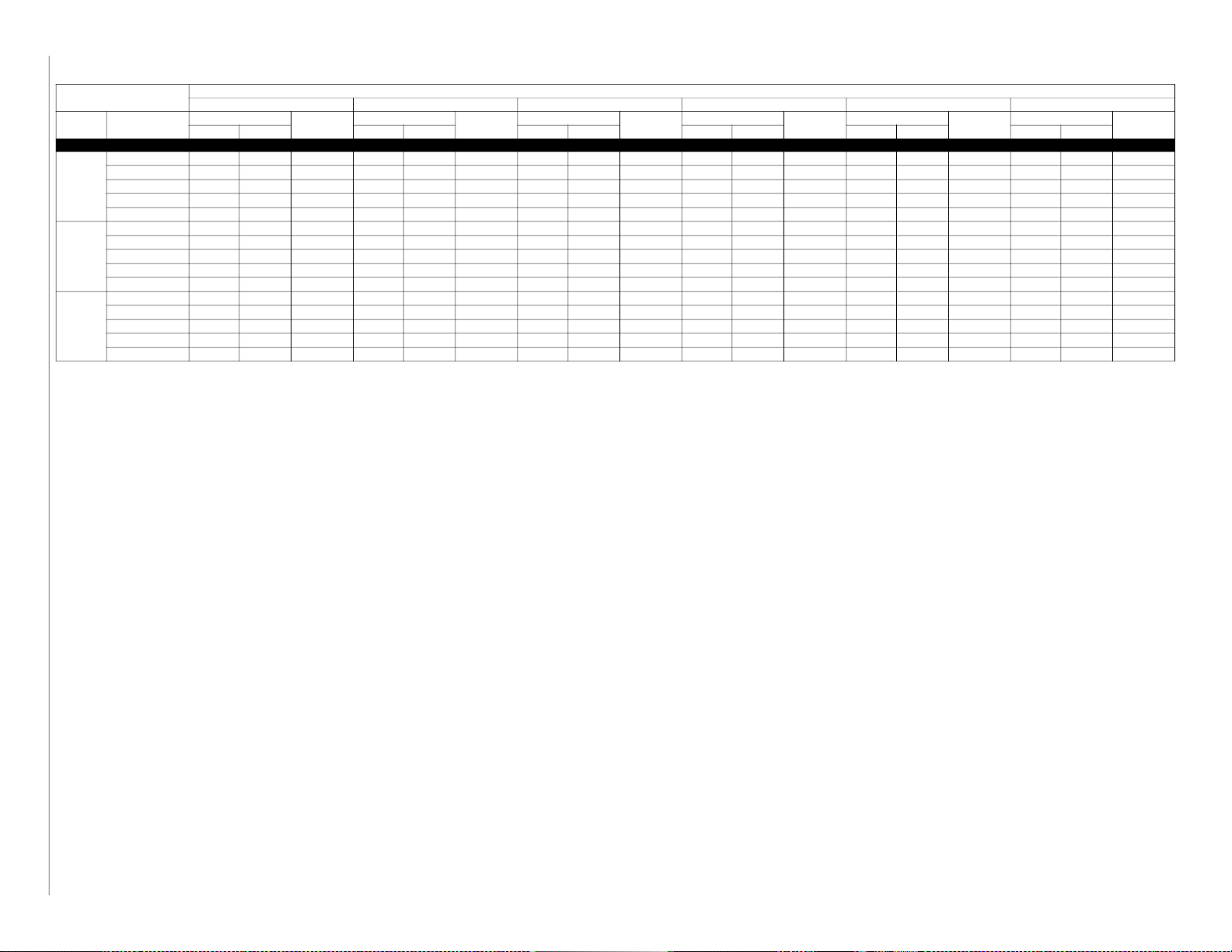
HEAT PUMP HEATING PERFORMANCE
INDOOR AIR
EDB CFM
Manufacturer reserves the right to change, at any time, specifications and designs without notice and without obligations.
65.0 (18.3)
70.0 (21.1)
75.0 (23.9)
65.0 (18.3)
70.0 (21.1)
75.0 (23.9)
65.0 (18.3)
15
70.0 (21.1)
75.0 (23.9)
65.0 (18.3)
70.0 (21.1)
75.0 (23.9)
65.0 (18.3)
70.0 (21.1)
75.0 (23.9)
525 6.31 5.80 1.06 8.24 7.57 1.12 10.33 9.42 1.18 12.82 11.39 1.25 14.99 13.64 1.32 17.43 17.43 1.39 19.89 19.89 1.46 22.25 22.25 1.53
600 6.44 5.92 1.07 8.39 7.71 1.13 10.49 9.57 1.18 12.98 11.53 1.24 15.17 13.81 1.30 17.65 17.65 1.37 20.05 20.05 1.42 22.35 22.35 1.49
675 6.56 6.03 1.09 8.52 7.83 1.14 10.64 9.70 1.19 13.11 11.65 1.24 15.33 13.95 1.29 17.84 17.84 1.35 20.16 20.16 1.40 22.39 22.39 1.46
525 5.98 5.50 1.11 7.94 7.30 1.17 10.04 9.15 1.24 12.60 11.19 1.31 14.79 13.46 1.38 17.18 17.18 1.46 19.51 19.51 1.53 21.99 21.99 1.61
600 6.10 5.61 1.12 8.08 7.42 1.18 10.20 9.30 1.24 12.76 11.33 1.30 14.96 13.61 1.36 17.40 17.40 1.43 19.80 19.80 1.50 22.01 22.01 1.57
675 6.21 5.71 1.13 8.21 7.54 1.18 10.34 9.43 1.24 12.90 11.46 1.30 15.11 13.75 1.35 17.59 17.59 1.42 19.93 19.93 1.47 22.16 22.16 1.53
525 5.66 5.21 1.15 7.64 7.02 1.22 9.76 8.90 1.29 12.12 10.77 1.36 14.59 13.28 1.45 16.93 16.93 1.53 19.52 19.52 1.61 21.74 21.74 1.69
600 5.77 5.31 1.16 7.78 7.15 1.23 9.91 9.04 1.29 12.36 10.98 1.36 14.75 13.42 1.43 17.15 17.15 1.50 19.69 19.69 1.57 21.85 21.85 1.64
675 5.88 5.41 1.18 7.90 7.26 1.24 10.05 9.16 1.29 12.68 11.26 1.36 14.90 13.56 1.42 17.33 17.33 1.49 19.79 19.79 1.55 21.89 21.89 1.61
700 9.25 8.51 1.46 11.80 10.84 1.51 14.65 13.36 1.57 17.55 15.59 1.64 20.48 18.64 1.70 23.72 23.72 1.76 26.48 26.48 1.81 29.22 29.22 1.87
780 9.37 8.62 1.47 11.95 10.98 1.51 15.04 13.71 1.58 17.71 15.73 1.62 20.68 18.82 1.68 23.86 23.86 1.73 26.51 26.51 1.78 29.14 29.14 1.83
900 9.54 8.77 1.49 12.15 11.16 1.52 15.24 13.90 1.58 17.92 15.92 1.62 20.93 19.05 1.67 23.93 23.93 1.71 26.50 26.50 1.75 28.95 28.95 1.79
700 8.92 8.20 1.52 11.47 10.54 1.58 14.22 12.97 1.64 17.33 15.39 1.72 20.20 18.38 1.78 23.45 23.45 1.85 26.22 26.22 1.90 28.63 28.63 1.96
780 9.04 8.31 1.54 11.62 10.68 1.58 14.40 13.13 1.64 17.48 15.53 1.71 20.40 18.56 1.76 23.60 23.60 1.82 26.26 26.26 1.87 28.88 28.88 1.92
900 9.21 8.47 1.55 11.81 10.85 1.59 14.66 13.37 1.64 17.69 15.71 1.70 20.65 18.79 1.75 23.86 23.86 1.79 26.27 26.27 1.83 28.80 28.80 1.87
700 8.57 7.88 1.59 11.12 10.22 1.65 13.86 12.64 1.71 17.09 15.18 1.81 19.92 18.13 1.87 23.12 23.12 1.95 25.95 25.95 2.00 28.41 28.41 2.05
780 8.69 7.99 1.60 11.27 10.36 1.65 14.03 12.79 1.71 17.25 15.32 1.79 20.11 18.30 1.85 23.32 23.32 1.92 26.00 26.00 1.96 28.60 28.60 2.01
900 8.86 8.15 1.62 11.47 10.54 1.67 14.26 13.00 1.72 17.45 15.50 1.78 20.36 18.53 1.84 23.49 23.49 1.88 26.03 26.03 1.93 28.48 28.48 1.97
875 10.57 9.72 1.64 13.85 12.73 1.72 17.28 15.76 1.79 21.23 18.86 1.89 24.67 22.45 1.96 28.51 28.51 2.04 32.89 32.89 2.15 38.06 38.06 2.28
1055 10.85 9.98 1.67 14.18 13.03 1.74 17.66 16.10 1.81 21.56 19.15 1.88 25.07 22.81 1.94 29.01 29.01 2.01 33.55 33.55 2.11 38.62 38.62 2.20
1125 10.95 10.07 1.68 14.29 13.13 1.75 17.79 16.22 1.81 21.68 19.26 1.89 25.21 22.94 1.94 29.17 29.17 2.01 33.76 33.76 2.10 38.73 38.73 2.19
875 10.08 9.27 1.70 13.39 12.30 1.79 16.83 15.35 1.87 20.92 18.58 1.97 24.34 22.15 2.05 28.12 28.12 2.14 32.38 32.38 2.25 37.46 37.46 2.39
1055 10.37 9.54 1.73 13.72 12.61 1.81 17.20 15.68 1.88 21.26 18.89 1.97 24.73 22.50 2.03 28.60 28.60 2.11 33.02 33.02 2.20 38.12 38.12 2.30
1125 10.47 9.63 1.75 13.83 12.71 1.82 17.33 15.80 1.89 21.39 19.00 1.97 24.86 22.62 2.03 28.76 28.76 2.10 33.23 33.23 2.20 38.25 38.25 2.29
875 9.59 8.82 1.76 12.92 11.87 1.86 16.38 14.94 1.95 20.21 17.95 2.04 24.00 21.84 2.14 27.72 27.72 2.24 31.88 31.88 2.35 36.84 36.84 2.51
1055 9.87 9.08 1.80 13.24 12.17 1.88 16.75 15.27 1.96 20.93 18.59 2.05 24.39 22.20 2.12 28.20 28.20 2.20 32.50 32.50 2.30 37.59 37.59 2.41
1125 9.96 9.16 1.81 13.35 12.27 1.89 16.87 15.38 1.97 21.05 18.70 2.06 24.52 22.31 2.12 28.36 28.36 2.20 32.70 32.70 2.30 37.75 37.75 2.39
1060 13.57 12.48 2.18 17.01 15.63 2.19 21.01 19.16 2.26 25.84 22.95 2.39 30.04 27.34 2.49 34.58 34.58 2.60 39.39 39.39 2.69 44.72 44.72 2.78
1200 13.82 12.71 2.20 17.30 15.90 2.20 21.35 19.47 2.27 26.14 23.22 2.38 30.41 27.67 2.48 35.06 35.06 2.58 39.98 39.98 2.67 45.47 45.47 2.74
1350 14.06 12.93 2.23 17.57 16.14 2.22 21.65 19.74 2.28 26.43 23.48 2.39 30.76 27.99 2.48 35.49 35.49 2.57 40.51 40.51 2.65 46.11 46.11 2.71
1060 12.97 11.93 2.28 16.42 15.09 2.29 20.40 18.60 2.35 25.37 22.54 2.48 29.53 26.87 2.59 34.00 34.00 2.69 38.63 38.63 2.79 43.93 43.93 2.89
1200 13.24 12.18 2.31 16.72 15.36 2.31 20.74 18.91 2.37 25.71 22.84 2.48 29.91 27.22 2.58 34.47 34.47 2.68 39.26 39.26 2.76 44.65 44.65 2.85
1350 13.47 12.39 2.34 16.99 15.61 2.33 21.06 19.20 2.39 26.01 23.10 2.49 30.27 27.55 2.58 34.90 34.90 2.67 39.81 39.81 2.75 45.29 45.29 2.82
1060 12.31 11.32 2.36 15.76 14.48 2.37 19.74 18.00 2.44 24.24 21.53 2.55 29.02 26.41 2.68 33.42 33.42 2.79 37.92 37.92 2.90 43.17 43.17 3.01
1200 12.56 11.55 2.39 16.05 14.75 2.39 20.08 18.31 2.45 24.77 22.00 2.56 29.40 26.75 2.67 33.88 33.88 2.78 38.68 38.68 2.88 43.86 43.86 2.96
1350 12.81 11.78 2.43 16.34 15.01 2.42 20.40 18.60 2.47 25.51 22.66 2.59 29.74 27.06 2.68 34.30 34.30 2.77 39.06 39.06 2.86 44.47 44.47 2.93
1240 16.99 15.63 2.54 21.52 19.77 2.66 26.48 24.15 2.78 31.94 28.37 2.92 36.98 33.65 3.05 42.60 42.60 3.19 48.96 48.96 3.38 55.33 55.33 3.53
1400 17.30 15.91 2.57 21.85 20.08 2.68 26.93 24.56 2.79 32.29 28.68 2.92 37.43 34.06 3.03 43.09 43.09 3.16 49.58 49.58 3.32 55.68 55.68 3.47
1575 17.60 16.19 2.61 22.18 20.38 2.70 27.39 24.98 2.81 32.63 28.99 2.92 37.82 34.42 3.03 43.57 43.57 3.15 50.05 50.05 3.29 56.08 56.08 3.43
1240 16.32 15.01 2.64 20.86 19.17 2.76 25.80 23.53 2.89 31.50 27.98 3.05 36.49 33.21 3.17 42.00 42.00 3.33 48.21 48.21 3.52 54.61 54.61 3.68
1400 16.61 15.28 2.67 21.21 19.49 2.78 26.19 23.88 2.90 31.84 28.28 3.04 36.90 33.58 3.16 42.66 42.66 3.30 48.84 48.84 3.46 55.06 55.06 3.61
1575 16.91 15.55 2.70 21.53 19.78 2.80 26.56 24.22 2.91 32.19 28.59 3.05 37.29 33.93 3.15 42.96 42.96 3.28 49.37 49.37 3.42 55.39 55.39 3.57
1240 15.58 14.33 2.73 20.17 18.53 2.86 25.12 22.91 3.00 31.06 27.59 3.18 35.99 32.75 3.31 41.41 41.41 3.47 47.45 47.45 3.67 53.91 53.91 3.83
1400 15.88 14.60 2.76 20.52 18.85 2.88 25.50 23.25 3.01 31.40 27.89 3.17 36.38 33.11 3.29 41.89 41.89 3.43 48.08 48.08 3.61 54.36 54.36 3.76
1575 16.17 14.87 2.80 20.84 19.15 2.91 25.86 23.58 3.02 31.74 28.19 3.17 36.63 33.33 3.28 42.35 42.35 3.42 48.64 48.64 3.57 54.67 54.67 3.72
-3.0 (-19.4) 7.0 (-13.9) 17.0 (-8.3) 27.0 (-2.8) 37.0 (2.8) 47.0 (8.3) 57.0 (13.9) 67.0 (19.4)
Capacity
MBtuh
Total Integ* Total In teg* Total Integ* Total Integ* Total Integ* Total Integ* Total Integ* Total Integ*
Total Sys.
KW†
Capacity
MBtuh
Total Sys.
KW†
OUTDOOR COIL ENTERING AIR TEMPERATURES °F (°C)
Capacity
MBtuh
Total Sys.
KW†
25SCA518A003 Outdoor Section With FJ4DNXA18L* Indoor Section
25SCA524A003 Outdoor Section With FJ4DNXB24L* Indoor Section
25SCA530A003 Outdoor Section With FJ4DNXB30L* Indoor Section
25SCA536A003 Outdoor Section With FJ4DNXB36L* Indoor Section
25SCA542A003 Outdoor Section With FJ4DNXC42L* Indoor Section
Capacity
MBtuh
Total Sys.
KW†
Capacity
MBtuh
Total Sys.
KW†
Capacity
MBtuh
Total Sys.
KW†
Capacity
MBtuh
Total Sys.
KW†
Capacity
MBtuh
Total Sys.
KW†
25SCA5: Product Data
Page 16

HEAT PUMP HEATING PERFORMANCE (Continued)
OUTDOOR COIL ENTERING AIR TEMPERATURES °F (°C)
Total Sys.
KW†
Capacity
MBtuh
Total Sys.
KW†
Capacity
MBtuh
Total Sys.
KW†
Capacity
MBtuh
Total Sys.
KW†
Manufacturer reserves the right to change, at any time, specifications and designs without notice and without obligations.
INDOOR AIR
EDB CFM
65.0 (18.3)
70.0 (21.1)
75.0 (23.9)
65.0 (18.3)
70.0 (21.1)
75.0 (23.9)
1390 19.57 18.00 2.85 24.39 22.41 2.96 29.74 27.12 3.07 35.56 31.59 3.20 41.01 37.32 3.31 47.17 47.17 3.45 54.37 54.37 3.63 62.01 62.01 3.78
1600 19.94 18.34 2.88 24.80 22.79 2.97 30.31 27.64 3.08 35.98 31.96 3.19 41.51 37.78 3.29 47.81 47.81 3.41 55.19 55.19 3.56 62.47 62.47 3.68
1800 20.25 18.62 2.91 25.15 23.11 3.00 31.02 28.29 3.11 36.32 32.26 3.20 41.92 38.15 3.28 48.32 48.32 3.39 55.75 55.75 3.51 62.68 62.68 3.63
1390 18.83 17.32 2.96 23.72 21.79 3.08 29.00 26.44 3.19 35.11 31.19 3.35 40.48 36.84 3.46 46.50 46.50 3.61 53.55 53.55 3.79 61.23 61.23 3.95
1600 19.20 17.66 2.99 24.11 22.15 3.10 29.46 26.86 3.20 35.51 31.54 3.34 40.96 37.27 3.44 47.13 47.13 3.56 54.36 54.36 3.73 61.68 61.68 3.85
1800 19.51 17.94 3.03 24.45 22.47 3.12 29.87 27.24 3.22 35.87 31.86 3.34 41.37 37.65 3.43 47.63 47.63 3.54 54.97 54.97 3.67 61.95 61.95 3.79
1390 18.07 16.62 3.08 23.00 21.13 3.20 28.29 25.80 3.33 34.68 30.81 3.50 39.98 36.38 3.62 45.84 45.84 3.77 52.73 52.73 3.96 60.36 60.36 4.12
1600 18.43 16.95 3.11 23.40 21.50 3.22 28.75 26.22 3.34 35.07 31.15 3.49 40.45 36.81 3.59 46.45 46.45 3.72 53.53 53.53 3.89 60.89 60.89 4.02
1800 18.74 17.23 3.14 23.74 21.81 3.25 29.13 26.56 3.35 35.43 31.47 3.49 40.85 37.17 3.58 46.95 46.95 3.70 54.15 54.15 3.84 61.18 61.18 3.96
1735 24.41 22.45 3.46 30.46 27.99 3.55 36.84 33.59 3.66 43.94 39.03 3.80 51.13 46.53 3.97 57.77 57.77 4.12 65.36 65.36 4.31 73.43 73.43 4.46
2000 24.94 22.94 3.51 31.05 28.53 3.59 37.49 34.18 3.68 45.49 40.41 3.84 51.78 47.12 3.95 58.57 58.57 4.09 66.39 66.39 4.25 74.12 74.12 4.37
2250 25.38 23.34 3.57 31.53 28.97 3.63 38.04 34.69 3.72 45.99 40.85 3.86 52.40 47.69 3.96 59.21 59.21 4.08 67.22 67.22 4.22 74.60 74.60 4.32
1735 23.25 21.38 3.59 29.39 27.00 3.68 35.80 32.64 3.80 42.69 37.92 3.95 50.48 45.94 4.14 57.00 57.00 4.31 64.36 64.36 4.50 72.44 72.44 4.66
2000 23.77 21.86 3.64 29.96 27.53 3.72 36.45 33.24 3.83 43.52 38.66 3.96 51.26 46.65 4.13 57.74 57.74 4.26 65.36 65.36 4.44 73.17 73.17 4.56
2250 24.21 22.27 3.70 30.44 27.97 3.77 36.98 33.72 3.86 44.15 39.22 3.98 51.61 46.97 4.13 58.36 58.36 4.25 66.17 66.17 4.40 73.65 73.65 4.51
1735 22.05 20.28 3.72 28.28 25.98 3.82 34.75 31.69 3.95 41.62 36.97 4.11 49.79 45.31 4.33 56.23 56.23 4.50 63.37 63.37 4.70 71.41 71.41 4.87
2000 22.56 20.75 3.77 28.85 26.51 3.86 35.38 32.26 3.98 42.37 37.64 4.11 50.41 45.87 4.31 56.98 56.98 4.45 64.35 64.35 4.63 72.18 72.18 4.76
2250 22.99 21.14 3.83 29.32 26.94 3.91 35.92 32.75 4.01 42.96 38.16 4.13 50.91 46.33 4.31 57.48 57.48 4.44 65.12 65.12 4.60 72.65 72.65 4.70
-3.0 (-19.4) 7.0 (-13.9) 17.0 (-8.3) 27.0 (-2.8) 37.0 (2.8) 47.0 (8.3) 57.0 (13.9) 67.0 (19.4)
Capacity
MBtuh
Total Integ* Total In teg* Total Integ* Total Integ* Total Integ* Total Integ* Total Integ* Total Integ*
Total Sys.
KW†
Capacity
MBtuh
Total Sys.
KW†
Capacity
MBtuh
25SCA548A003 Outdoor Section With FJ4DNXC48L* Indoor Section
25SCA560A003 Outdoor Section With FJ4DNXD60L* Indoor Section
NOTE: When the required data falls between the published data, interpolation may be performed. Extrapolation is not an acceptable practice.
* The Btuh heating capacity values shown are net integrated values from which the defrost effect has been subtracted. The Btuh heating from supplement heaters should be added to those values to obtain total Sys. capacity.
{ The kW values include the compressor, outdoor fan motor, and indoor blower motor. The kW from supplement heaters should be added to these values to obtain total Sys. kilowatts.
EDB — Entering Dry Bulb2
16
Capacity
MBtuh
Total Sys.
KW†
Capacity
MBtuh
Total Sys.
KW†
25SCA5: Product Data
Page 17

25SCA5: Product Data
Guide Specifications General
System Description
Outdoor-mounted, air-cooled, split-system heat pump unit suitable for
ground or rooftop installation. Unit consists of a hermetic compressor, an
air-cooled coil, propeller-type condenser fan, and a control box. Unit
will discharge supply air upward as shown on contract drawings. Unit
will be used in a refrigeration circuit to match up to a packaged fan coil
or coil unit.
Quality Assurance
– Unit will be rated in accordance with the latest edition of AHRI
Standard 210/240.
– Unit will be certified for capacity and efficiency, and listed in the
latest AHRI directory.
– Unit construction will comply with latest edition of ANSI/
ASHRAE and with NEC.
– Unit will be constructed in accordance with UL standards and will
carry the UL label of approval. Unit will have C-UL approval.
– Unit cabinet will be capable of withstanding Federal Test Method
Standard No. 141 (Method 6061) 500-hr salt spray test.
– Air-cooled condenser coils are pressure tested and the outdoor unit
is leak tested.
– Unit constructed in ISO9001 approved facility.
Delivery, Storage, and Handling
Unit will be shipped as single package only and is stored and
handled per unit manufacturer’s recommendations.
Warranty (for inclusion by specifying engineer)
U.S. and Canada only.
Air-Cooled, Split-System Heat Pump
25SCA5
1-1/2 to 5 nominal tons
Refrigeration Components
Refrigeration circuit components will include liquid-line shutoff
valve with sweat connections, vapor-line shutoff valve with sweat
connections, system charge of Puron® refrigerant, POE compressor
oil, accumulator, and reversing valve.
Operating Characteristics
The capacity of the unit will meet or exceed _____ Btuh at a suction
temperature of _____ _F/_C. The power consumption at full load
will not exceed _____ kW.
Combination of the unit and the evaporator or fan coil unit will
have a total net cooling capacity of _____ Btuh or greater at
conditions of _____ CFM entering air temperature at the evaporator
at _____ _F wet bulb and _____ _F/_C dry bulb, and air entering
the unit at _____ _F/_C.
The system will have a SEER of _____ Btuh/watt or greater at DOE
conditions.
Electrical Requirements
Nominal unit electrical characteristics will be _____ v, single
phase, 60 hz. The unit will be capable of satisfactory operation
within voltage limits of _____ v to _____ v.
Unit electrical power will be single point connection.
Control circuit will be 24v.
Special Features
Refer to section of this literature identifying accessories and
descriptions for specific features and available enhancements.
PRODUCTS
Equipment
Factory assembled, single piece, air-cooled heat pump unit.
Contained within the unit enclosure is all factory wiring, piping,
controls, compressor, refrigerant charge Puron®, and special
features required prior to field start-up.
Unit Cabinet
Unit cabinet will be constructed of galvanized steel and coated with
pre-paint.
Available with dense grille only.
Fans
Condenser fan will be direct-drive propeller type, discharging air
upward.
Condenser fan motors will be totally enclosed, 1-phase type with
class B insulation and permanently lubricated bearings.
Shafts will be corrosion resistant.
Fan blades will be statically and dynamically balanced.
Condenser fan openings will be equipped with steel wire safety
guards.
Compressor
Compressor will be hermetically sealed.
Compressor will be mounted on rubber vibration isolators.
Condenser Coil
Condenser coil will be air cooled.
Coil will be constructed of aluminum fins mechanically bonded to
copper or aluminum tubes which are then cleaned, dehydrated, and
sealed.
Manufacturer reserves the right to change, at any time, specifications and designs without notice and without obligations.
17
Page 18

25SCA5: Product Data
System Design Summary
1. Intended for outdoor installation with free air inlet and outlet. Outdoor fan external static pressure available is less than 0.01-in. wc.
2. Minimum outdoor operating air temperature without low-ambient operation accessory is 55_F (12.8_C).
3. Maximum outdoor operating air temperature for cooling mode is 125_F (51.7_C).
4. Minimum outdoor operating air temperature for heating mode is –10_F (–23.3_C).
5. Maximum outdoor operating air temperature for heating mode is 66_F (18.9_C).
6. For reliable operation, unit should be level in all horizontal planes.
7. For interconnecting refrigerant tube lengths greater than 80 ft (23.4 m) and/or elevation differences between indoor and outdoor units greater than
20 ft (6.1 m), consult Residential Piping and Longline Guideline and Service Manual available from equipment distributor.
8. If any refrigerant tubing is buried, provide a 6 in. (152.4 mm) vertical rise to the valve connections at the unit. Refrigerant tubing lengths up to 36
in. (914.4 mm) may be buried without further consideration. Do not bury refrigerant lines longer than 36 in. (914.4 mm).
9. Use only copper wire for electric connection at unit. Aluminum and clad aluminum are not acceptable for the type of connector provided.
10. Do not apply capillary tube indoor coils to these units.
11. Factory-supplied filter drier must be installed
© 2022 Carrier. All rights reserved.
Manufacturer reserves the right to change, at any time, specifications and designs without notice and without obligations.
Edition Date: 09/22
18
Catalog No: 25SCA5-01PD
Replaces: New
 Loading...