

Page 1
Carrier
Centrifugal Fan Air-Cooled Condenser
Installation Instructions
09FA
INTRODUCTION
The 09FA Centrifugal Air-Cooled Condensers
are designed for indoor installations. If outdoor
installation is desired, a weather enclosure must be
constructed around the unit.
UNIT LOCATION
Allow sufficient clearance for:
1. Removal of fan shaft and coil.
2. Service of fan motor, bearings, damper motor
and linkage (at least 30 inches)
3. Unit air supply (minimum distance of 4 feet
from ceiling, wall, or floor when supplied from
one side only).
PRE-INSTALLATION
1 File claim with shipping company if shipment is
damaged or incomplete.
2. Examine unit nameplate to verify that electrical
requirements match available power supply.
3. Rotate fans by hand. Check for freedom of
rotation and secureness to fan shaft.
4. Remove shipping straps from skid and unit.
INSTALLATION
Observe the following-
1. When rigging, do not support unit weight by
fan shaft extension or coil connections Put
rigging medium completely around unit, using
spreader bars to ensure that sling lifts at the
skid without touching the unit sides.
2. Remove coil piping connection protective caps
only when ready to connect piping.
3. Exercise reasonable care not to bend or muti
late coil fins.
4. On bypass units, where bypass is not desired,
block off opening with a strip of sheet metal
(field-supplied) and secure.
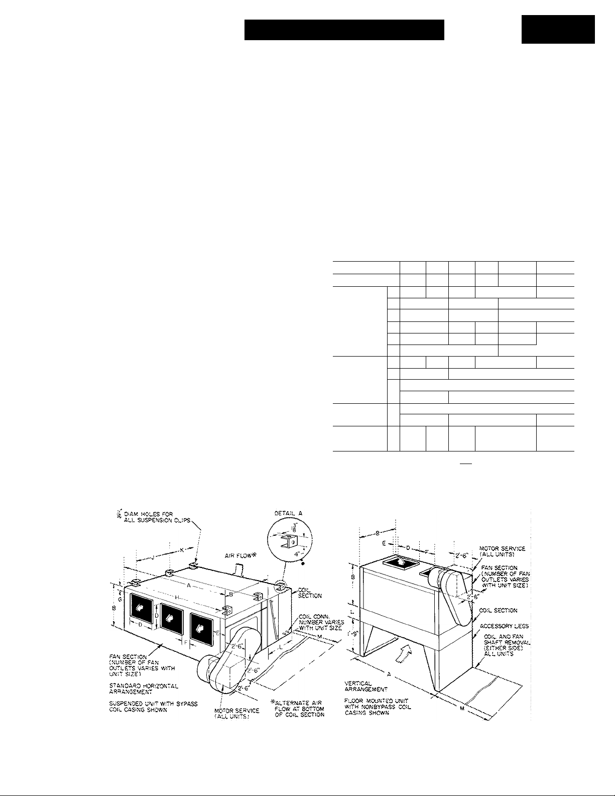
Unit Mounting (Fig. 1 and Table 1)
HORIZONTAL ARRANGEMENT (Standard)
1 Remove plug buttons covering captive nuts
used to fasten suspension clips.
Table 1 — Dimensions (ft-in.) and
Mounting Information
UNIT 09FA
OPTG WT (lb)*
DIM. FAN
SECTION
DIM SUSPENSION
CLIPS
DIM. COIL
SECTION!
DIM. SERV
ICE AREA
3 Nonbypass Coi
'^Includes fan .section; coi I section with nonbypass coil cosi
taining condensing coil with operating charge
tRefer to Fig 3 for coil connections
006 008 012
725 980
A
3-1OV2
B
1- 9
D
0-11 Va
E
0- 6
F
0-10% 0-9‘/2 1- 0% 2-1%
G
H
3- 7%
J
1- 2
;- 3 I
K
1- 9
1- 3
L
1- 9
M
5- 6 7-2 6- 8
1080 1410
5-6% 4-11%
2-4
1 -4%
6- 0%
0%
5-3% 4-8%
1-9 i 2-5%
I 1 Bypass Coi I
016 024 028
1720
7- 1% 9-9
3-0‘/2
1 -8%
I-IV16 0-ll“4e
1- 7%
0-1
6-10%2
1-1OV2 1 2- 1V2
I
1-1OV2
8- 9
034 044
2290
O-IF/16
1- 3%
9- 6%
2- 7%
11-5
ng con-
© Carrier Corporation 1968
Certified dimension drawings available on request
Fig. 1 — Dimensions
09FA-1SI
Page 2
2. Bolt suspension clips (supplied), one near each
corner of fan section and one near each end of
coil section. Tighten bolts (supplied) securely.
3. Lift unit into position.
4. Pass threaded hanger rod (field-supplied) thru
each suspension clip.
5. Fasten with nuts (field-supplied).
VERTICAL ARRANGEMENT
1. Bolt legs (accessory) to inlet side of coil
section, using 5/8 in. - 11 captive nuts (located
on inward flanges of coil section) and bolts
(supplied). Tighten securely.
2. Rotate motor end bells 90 degrees so drain
holes are at bottom. Rotating end bells must be
performed by an authorized vendor’s motor
repair shop.
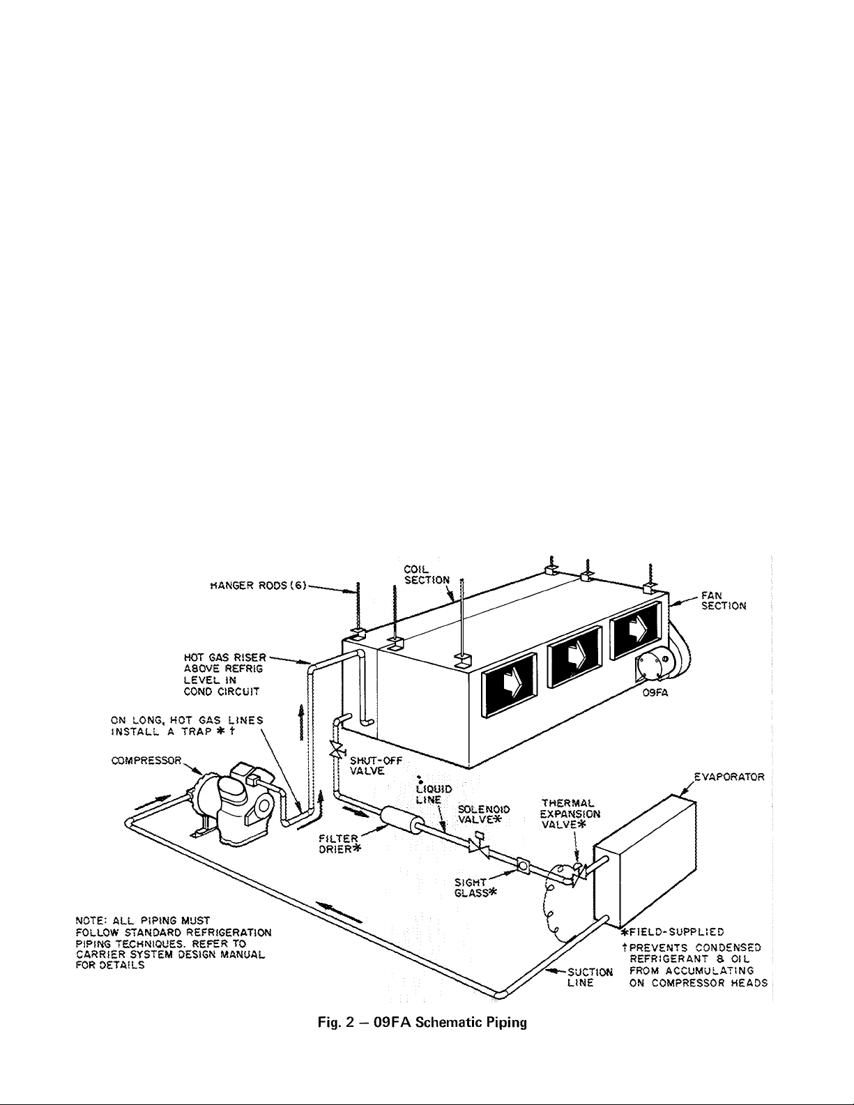
Refrigerant Piping
GENERAL — All field leak and pressure testing
should be in accordance with local code require
ments. If no local code exists, use American
Standard Safety Code for Mechanical Refrigeration
(A.S.A. B9.1).
Eor leak testing procedures, refer to the Carrier
Standard Service Techniques Manual, Chapter 1,
Section 1-6.
Refrigerant line sizing depends on length of
lines between various sections of the refrigerant
system. Consider the amount of liquid lift and
drop in the system as well as proper compressor oil
return. Consult Carrier System Design Manual, Part
3, for proper piping sizes and design.
Liquid and hot gas connections for any one
split are same size so coil may be reversed for
opposite-hand connection, but must be piped for
counter flow in any case.
LIQUID SHUT-OEF VALVE AND SIGHT GLASS
— Shut-off valve is not supplied with units. It is
strongly recommended that a full line size liquid
shut-off valve be field supplied near condenser to
allow for servicing parts of the refrigerant circuit.
A field-supplied, moisture-indicating sight glass is
recommended for use in charging and servicing the
system. Refer to Fig. 2 for location.
The American Standard Safety Code for
Mechanical Refrigeration (A.S.A. B9.1, 1964, para
graph 12.1) states as follows: “Every refrigerating
system shall be protected by a pressure relief
device unless so constructed that the pressures due
to fire conditions will be safely relieved by some
part of the system.” Since the 09FA units have no
pressure relief device, it should be field supplied
and installed. When the split coil is used with
multiple systems, each system must have a pressure
relief.
COIL CONNECTIONS - Refer to Eig. 2, 3. Make
connections.
Page 3

_
p“® o
^37.5%
25%
UNIT 09FA
UNIT 09FA044
o-
o
a
COIL CONN. SIZES (IN.)
UNIT
SIZE
006
008
012
016
024
028
034
044*
^CONNECTION SIZES ARE ODM AND ARE
SHIPPED LESS MANIFOLD. ALL MANIFOLD
LINE CONNECTION SIZES ARE |1 IN. ODM
LARGE SMALL
__
—
—
l|
If
If
If
If
—
-
5
8
5
6
5
8
ALL MANIFOLDS MUST BE FIELD INSTALLED
№ LIQUID
Q HOT GAS
ACCESSORY MANIFOLD (044 SIZE ONLY) ALL
OTHER MANIFOLDS MUST BE FIELD SUPPLIED.
□
Fig. 3 — Coil Face Splits and Connections
Electrical Wiring — Refer to Table 2; motor
manufacturer’s wiring diagram, supplied with
motor; and motor starter (field-supplied) wiring
diagram.
All wiring must comply with applicable local
and national codes.
Table 2 — Electrical Data (60-Cycle, 3-Phase)
UNIT
09FA
006 2 184
008
012 208
016
024 5 215
028
034 10
044 15
For ful I load amps, locked rotor amps, and wire sizing
amps, refer to National Electrical Code or motor man
ufacturer's recommendations.
VOLTS
220/440 1750
HP RPM
3 213
Final Inspection Check List
1. Remove debris from unit interior.
0
2. Check lubrication of fan shaft and motor
bearings. Follow fan motor manufacturer’s
NEMA
FRAME
256 U
284 U
STANDARD
(044 COIL)
recommendations. Fan bearings are prelubri
cated and require no further lubrication the
first year of operation. Refer to 09FA Start-Up
and Service Instructions for detailed bearing
lubrication.
3. Check secureness of motor and mounting
bracket.
4. Check sheave alignment and belt tension.
5. Check secureness of fan shaft bearings.
6. Check secureness of sheaves to fan and motor
shafts.
7. Recheck fan wheels for:
a. Freedom of rotation within fan housings.
b. Concentric alignment with fan housing inlet
opening.
c. Balance with fan shaft.
d. Secureness to fan shaft.
NOTE; If needed, refer to 09FA Start-Up and
Service Instructions for points 4, 5, 6, and 7.
8. Check direction of fan wheel rotation. Refer to
arrow on bearing plate nearest motor for proper
rotation.
9. Check fan speed.
Page 4

Manufacturer reserves the right to change any product specifications without notice
CARRIER AIR CONDITIONING COMPANY • SYRACUSE, NEW YORK
Tab 5 Form09FAdSI New Printed in U S A 1070 4-68 Codes C and MC Catalog No 530-933
 Loading...