

Page 1
HEATING & COOLING
Installation, Start-Up and
Service Instructions
CONTENTS
Page
SAFETY CONSIDERATIONS
INSTALLATION
Step 1 — Complete Pre-Installation
Checks ...............................................
Step 2 — Rig and Place Unit ...............
• RIGGING
• PLACING THE UNIT
Step 3 — Complete Refrigerant Piping
•
GENERAL
COIL REFRIGERANT PIPING INSTALLATION
TUBING PACKAGE INSTALLATION
THREE AND FOUR COIL SPLIT, COIL
CIRCUITING APPLICATIONS; 054-084 UNITS
ONLY
• REFRIGERANT LINE SIZING
• LIQUID SHUTOFF VALVE AND SIGHT GLASS
• PRESSURE RELIEF
• REFRIGERANT RECEIVER
• LIQUID LIFT
Step 4 — Complete Electrical
Connections...................................................................23
• GENERAL
• FIELD CONNECTIONS
• MAIN POWER WIRING
• CONTROL CIRCUIT POWER WIRING
• GENERAL WIRING NOTES
• DESCRIPTION OF CONTROLS
Step 5 — Add Accessories as Needed
START-UP........................................................................32
System Evacuation and
Dehydration
Charging Procedure .........................................................32
Check Operation of Condenser Fan Motor
Controls and Rotation of Fans
SERVICE .......................................................................32-34
Cleaning Condenser Coiis
Condenser Fans
Lubrication ........................................................................32
Head Pressure Control.....................................................32
• FAN CYCLING
.....................................
..................................................................
.................................................................
...............
............................
....................................
...............................................
SAFETY CONSIDERATIONS
Installing, starting up, and servicing air-conditioning equip
ment can be hazardous due to system pressures, electrical
components, and equipment location (roofs, elevated struc
tures, etc.).
Only trained, qualified installers and service mechanics
should install, start up, and service this equipment (Fig. 1).
Untrained personnel can perform basic maintenance func
tions such as cleaning coils. All other operations should be
performed by trained service personnel.
...........1
........
1-31
1
4
31
32
32
32
32 ,
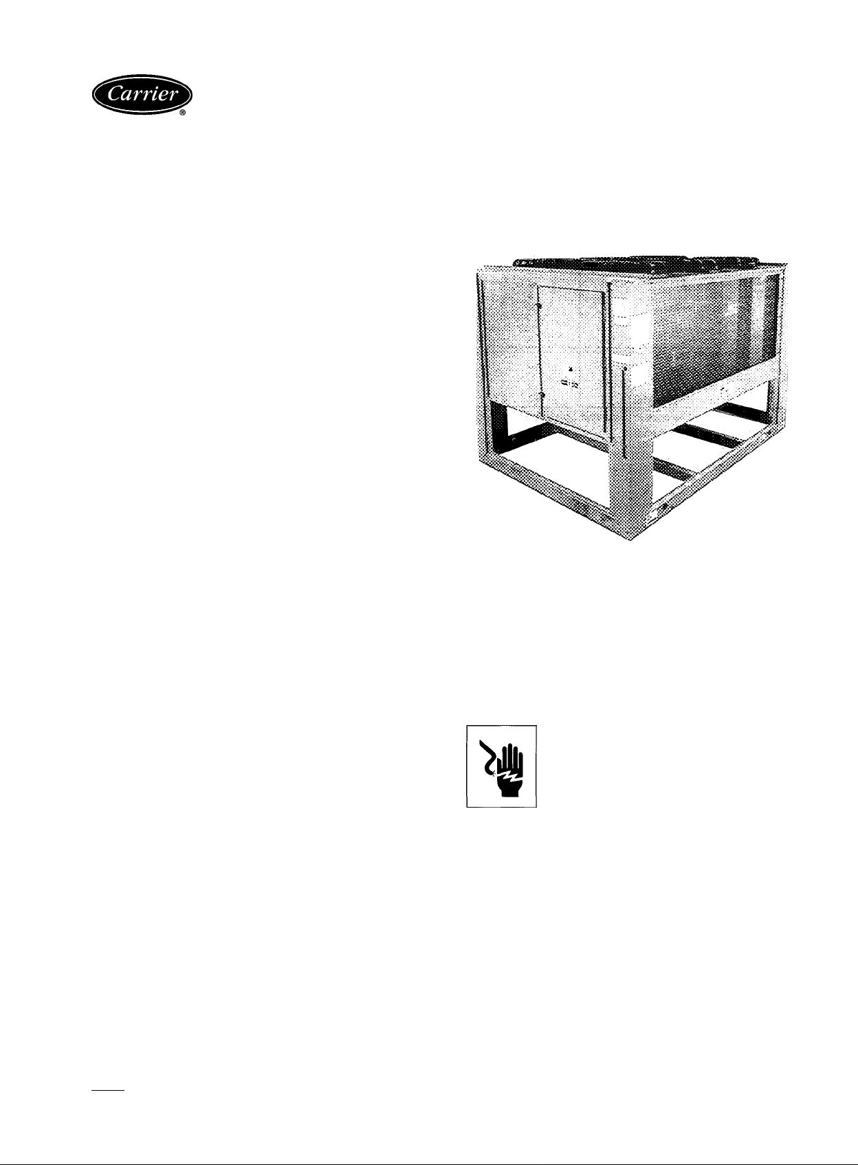
09DK054-094
Air-Cooled Condenser Units
50/60 Hz
Fig. 1 — Model 09DK (084 Shown)
When working on the equipment, observe precautions in
the literature and on tags, stickers, and labels attached to
the equipment.
Follow all safety codes. Wear safety glasses and work
gloves. Keep quenching cloth and fire extinguisher nearby
when brazing. Use care in handling, rigging and setting bulky
equipment.
See Tables lA and IB for Physical Data.
ELECTRIC SHOCK HAZARD
Separate power sources (main and control
power circuits) are used for these units. Be
sure both main and control power circuits
are disconnected before servicing.
INSTALLATION
Step 1 — Complete Pre-Installation Checks —
Examine for damage incurred during shipment. File claim
immediately with transit company if damage is found. Check
the shipment for completeness. Verify that the nameplate
electrical requirements match the available power supply
Manufacturer reserves the right to discontinue, or change at any time, specifications or designs without notice and without incurring obiigations.
Book 12 PC 111 Catalog No 530-959 Printed in U S A. Form 09DK-9SI Pg 1 2-94 Replaces: 09DK-4SI
Tab 4a
Page 2
Table IA — Physical Data 60 Hz
09DK
NOMINAL TONS
OPERATING WEIGHT-lb
Cu-AI*
Cu-Cut
SHIPPING WEIGHT-lb“
Cu-AI*
Cu-Cut
REFRIGERANTS
NOMINAL HEAT REJECTION
(TONS)tt
CONDENSER FANS
No. of Blades
No. of Fans
Fan DIameter-ln.
AIrflow-cfm
Fan Speed-rpm 1140
Fan Motor-hp
CONDENSER COILS
Quantity
Fins/ln.
No. of Rows
Total Face Area (sq ft)
TD - Temperature Difference = Saturated Condensing Temperature - Entering-Air Temperature
‘Copper tubes and aluminum fins
tCopper tubes and copper fins.
“Packaging option includes skid and coil protection.
ttNominal heat rejection based on refrigerant R-22, 15“ F subcooling, and a 30“ F temperature difference (TD).
054
50
1695
1983 2278
2010
2298 2569
65.8
4
4
30
35,000
1
4
17
2
80.5
English
064
60
1845
2136 2521 2725 4415
R-134A, R-22, R-12, R-500, R-502
78 6 95 4 103 5
4 4
4 6 6
30 30 30
35,000 52,000 51,000
1140 1140 1140
1
4
17
3 2 3
80 5 116.7 116.7
074
70
2200
2617 3099
2938 3403 5150
1 1
4 4
17 17
084
80
2421
4
094
90
2850
3560
1163
4
6
30
57,000
1140
1
4
17
3
128.3
SI
09DK
NOMINAL kW
OPERATING WEIGHT-kg
Cu-AI*
Cu-Cut
SHIPPING WEIGHT-kg**
Cu-AI*
Cu-Cut
REFRIGERANTS
NOMINAL HEAT REJECTION
(kW)tt
CONDENSER FANS
No. of Blades
No. of Fans
Fan DIameter-mm
AIrflow-L/s
Fan Speed-r/s
Fan Motor-kW
CONDENSER COILS
Quantity
FIns/m 669
No. of Rows
Total Face Area (sq m)
TD — Temperature Difference = Saturated Condensing Temperature - Entering-Air Temperature
‘Copper tubes and aluminum fins.
TCopper tubes and copper fins.
“Packaging option includes skid and coil protection.
ttNominal heat rejection based on refrigerant R-22, 8.3“ C subcooling, and a 16.7“ C temperature difference (TD)
054
176
769
900
912
1042
231
4
4
762
16 520
19
0 746
4
2 3
75
064 074 084 094
211
837
1033 1187 1406
969 1144 1236
1165
R-134A, R-22, R-12, R-500, R-502
276 335
4 4
4 6
762 762
16 520
19 19 19 19
0.746 0.746
4
609 669
7.5 10.84
246 281 316
998 1098 1293
1333
24 540
4
2 3
1615
1544
364
4 4
6
762 762
24 070 26 900
0.746
4 4
669 669
10.84 11 92
2003
2336
409
6
0.746
3
©
Page 3
Table IB — Physical Data 50 Hz
09DK
NOMINAL TONS
OPERATING WEIGHT-lb
Cu-AI*
Cu-Cut
SHIPPING WEIGHT-lb"
Cu-AI* 2010 2136
Cu-Cut
REFRIGERANTS R-134A, R-22, R-12, R-500, R-502
NOMINAL HEAT REJECTION
(TONS)tt
CONDENSER FANS
No. of Blades
No. of Fans
Fan Diameter-in. 30 30 30
Airfiow-cfm 35,000 35,000 52,000
Fan Speed-rpm 950 950 950
Fan Motor-hp
CONDENSER COILS 4
Quantity
Fins/in.
No. of Rows
Totai Face Area (sq ft)
TD — Temperature Difference = Saturated Condensing Temperature - Entering-Air Temperature
'Copper tubes and aluminum fins.
tCopper tubes and copper fins
"Packaging option includes skid and coil protection.
ttNominal heat rejection based on refrigerant R-22, 15° F subcooling, and a 30° F temperature difference (TD)
054
50
1695
1983
2298 2569 2938
65 8 78.6 95.4
6 6 6
4
1
4 4 4
17 17 17 17 17
2
80.5 80.5 1167
English
064
60
1845 2200
2278
4 6
1 1 1 1
3
074 084
70 80
2617
2521
2
094
90
2421 2850
3099
2725
3403
103 5
6
6
30
51,000
950
4
3 3
116.7 128.3
3560
4415
5150
116.3
30
57,000
950
6
6
4
SI
09DK 054 064 074 084 094
NOMINAL kW 176
OPERATING WEIGHT-kg
Cu-AI*
Cu-Cut
SHIPPING WEIGHT-kg**
Cu-AI*
Cu-Cut
REFRIGERANTS
NOMINAL HEAT REJECTION
(kW)tt
CONDENSER FANS
No. Of Blades
No. of Fans
Fan Diameter-mm 762 762 762 762
Airflow-L/s
Fan Speed-r/s
Fan Motor-kW 0.746 0.746 0.746
CONDENSER COILS
Quantity
Fins/m
No. of Rows
Total Face Area (sq m)
TD — Temperature Difference = Saturated Condensing Temperature - Entering-Air Temperature
‘Copper tubes and aluminum fins.
tCopper tubes and copper fins.
"Packaging option includes skid and coil protection.
ttNominal heat rejection based on refrigerant R-22, 8.3° C subcooling, and a 16.7° C temperature difference (TD).
769 837 998 1098 1293
900
912
1042
231 276 335 364
6 6 6
4 4 6
16 520
15.8
4 4 4
669
2
7.5 7.5 10 84 10 84 11.92
211
1033
969
1165 1333
R-134A, R-22, R-12, R-500 R-502
16 520
158
669 669 669
3
246 281
1187 1406 1615
1144
24 540
15.8
2
24 070
316
1236
1544 2336
6
6
158
0.746
4
3 3
2003
409
6
6
762
26 900
15.8
0.746
4
669
Page 4
Step 2 — Rig and Place Unit
RIGGING - The 09DK units are designed for overhead
rigging and this method should be used Lifting holes are
provided in the frame base rails, which are marked for rig
ging (see rigging label on the unit). It is recommended that
field supplied pipes of sufficient length that extend beyond
the frame are passed through the holes. Attach cables, chains,
or straps to both ends of the pipes. Use spreader bars or a
frame to keep the cables, chains, or straps clear of the unit
sides. All cables should run to a central suspension point
so that the angle from the horizontal is not less than
45 degrees. See Fig. 2-4 and Tables lA and IB for weight
distribution information. Standard coil protection packag
ing provides some protection to the unit. Raise and set the
unit down carefully.
Domestic Units With No Overhead Rigging— Standard con
denser packaging consists of coil protection only. Skids are
not provided as part of the standard packaging. If overhead
rigging is not available at the jobsite, place the unit on a
skid or pad by using jacks at the rigging points before drag
ging or rolling. When rolling, use a minimum of 3 rollers.
When dragging, pull the pad or skid.
Do not apply pressure
to the unit. Raise from above to lift off the pad or skid
when in final position. See rigging section above for more
information.
Export and Domestic Units With Skids— All export units
are mounted on skids with vertical coil protection. Leave
the unit on the skid until it is in the final position. While on
the skid, the unit can be rolled, dragged or forklifted; do
not apply force to the unit. Use a minimum of 3 rollers
when rolling, and raise from above to remove the skid when
unit is in the final position. See preceding rigging proce
dure for more information.
A CAUTION
To avoid damage to units, do not forklift them unless
they are attached to skids designed for forklifting. Fork
lift trucks used to lift units on skids must have forks a
minimum of 60 in. (1524 mm) long.
Step 3 — Complete Refrigerant Piping
GENERAL — All field leak and pressure testing should be
in accordance with local code requirements. If a local code
does not exist, use ASHRAE (American Society of Heat
ing, Refrigeration and Air Conditioning Engineers) Stand
ard 15, Safety Code for Mechanical Refrigeration.
For leak testing procedures, refer to the Carrier
“Refrigerant Service Techniques” book. Form SM-IA
For any parts that need to be removed, use a mini tubing
cutter. Perform phos-copper brazing on all field-made con
nections while protecting adjacent joints from heat.
Install or replace filter-drier(s).
COIL REFRIGERANT PIPING INSTALLATION - Hot
gas and liquid connections are located on the same end and
have a heat-shrunk cap, which ensures a clean joint for field
piping. The coil circuiting is designed to provide several
selections of coil splits to satisfy various applications (See
Table 2), with piping connections made in the field. In all
cases where circuits are field connected, the piping connec
tions should be made within the unit cabinet The hot gas
lines should enter and the liquid lines should leave the con
denser at the header end of the unit.
A tubing package for headering, including two fan cycle
pressure switches (FCPSs) and hardware, is provided for
the 100, 50/50, and nominal 67/33% (054-084 only) con
denser coil circuiting options. The tubing also provides
ports for easy FCPS installations. The ports come with a
1/4-in. male flare fitting and check valve for each FCPS
replacement. Tubing and FCPSs are field installed regard
less of circuiting. Tubing packages are not offered for the
33/33/33% and 33/33/17/17% coil circuiting options; tub
ing for these coil circuit options must be field fabricated
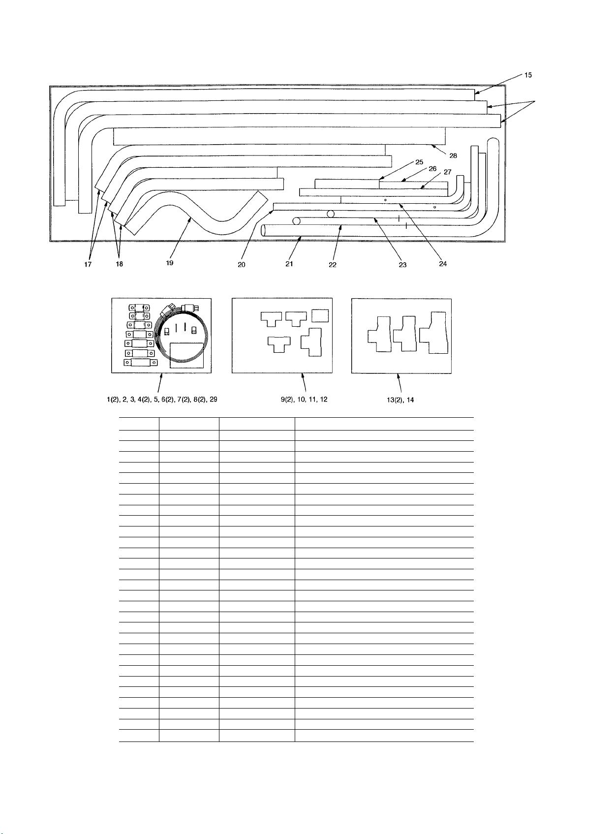
and installed. See Fig. 5-7 for tubing package contents
NOTE. 67/33, 33/33/33 and 33/33/17/17% represent aver
age coil split combinations. Refer to sections below for ac
tual values for your particular coil split combination. Note
that 09DK094 units can only have 100% or 50/50% splits.
PLACING THE UNIT — Locate the condenser where an
adequate supply of outdoor air is available for the unit in
let. Do not locate where the possibility of air recirculation
exists, such as under a roof overhang. Also, locate the con
denser in an area free from airborne dirt or other foreign
material which could clog the condenser coils. Refer to
Fig. 2-4 for airflow clearances For multiple units, allow
8 ft (2440 mm) separation between units for airflow and
service. Placement area must be level and strong enough
to support operating weight of the unit (Fig. 2-4 and
Tables lA and IB). It is recommended to bolt unit securely
to pad when unit is positioned and leveled. Fasteners for
mounting unit are field supplied. If vibration isolators are
required for a particular installation, refer to the unit weight
distribution data tables in Fig. 2-4 to help select the proper
isolators.
Table 2 — Coil Circuiting Options
09DK
054
064
074
084
094
100% 50/50% 66/34
100% 50/50% 66/34
100% 50/50%
100% 50/50% 67/33
100% 50/50%
IMPORTANT: With the 67/33, 33/33/33, and 33/33/
17/17% capacity split options, 3 or 4 FCPSs are used
For these applications, an accessory fan control kit is
required. See accessory installation instmctions for more
information.
Figure 8 shows a typical piping application for a condenser
with a multiple-split system. Figure 9 shows the typical field
piping arrangements for the 09DK units. See Fig. 10 and
11 for coil connection details. Figures 12 and 13 show typ-
*,ical factory supplied coil circuiting and typical field in
stalled 67/33% coil split circuiting, respectively.
09DK CIRCUITING OPTIONS
68/32
-
34/34/32
34/34/32
32/32/36
33/33/33
-
34/34/16/16
34/34/16/16
32/32/18/18
33/33/17/17
-
Page 5
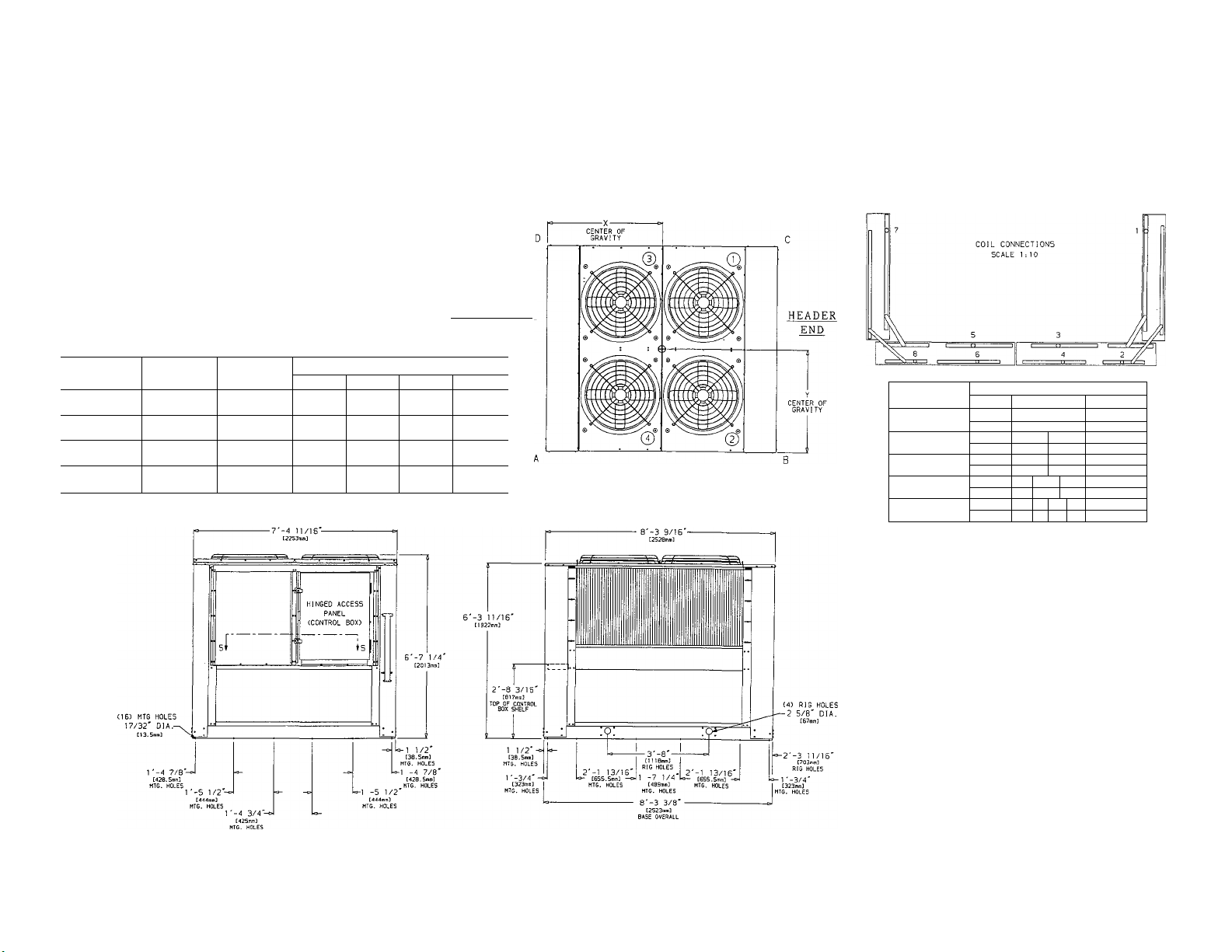
NOTES:
1. The approximate operating weight of the unit is:
09DK-054—
09DK-054-C-------------»• 1983 lb [900 kg]
09DK-064
09DK-064-C-------------»-2278 lb [1033 kg]
2. Unit must have clearances for airflow as follows:
Top — Do not restrict in any way.
________
----------------
► 1695 lb [769 kg]
>■ 1845 lb [837 kg]
Ends — 5 ft [1524 mm]
Sides — 6 ft [1829 mm]
3. All units are shipped with a capacity split tubing kit. This kit may be used by
the field to obtain 100%, 50%/50% and 67%/33% capacity splits. To obtain
a 33%/33%/33% capacity split, coils must be manifolded by the field. Coils
are factory circuited for a 33%/33%/17%/17% capacity split.
UNIT
09DK-054—
09DK-054-C
09DK-064—
09DK-064-C
DIMENSION
Y X
3'-6 11/16"
[1084 mm]
3'-6 7/8"
[1090 mm]
3'-6 3/4"
[1087 mm]
3'-7 1/8"
[1095 mm]
DIMENSION
4'-1/8"
[1222 mm]
4'-5/16"
[1227 mm]
4'-3/16"
[1224 mm]
4'-1/2"
[1232 mm]
OPERATING CORNER WEIGHTS
A В C
452 lb
[205 kg]
524 lb
[238 kg]
489 lb
[222 kg]
598 lb
[271 kg]
425 lb
[193 kg]
497 lb
[225 kg]
462 lb
[210 kg]
571 Ib
[259 kg]
396 Ib
[180 kg]
468 Ib
[212 kg]
434 Ib
[197 kg]
542 Ib
[246 kg]
CONTROL BOX
END
D
422 Ib
[191 kg]
494 Ib
[224 kg]
459 Ib
[208 kg]
568 Ib
[258 kg]
CAPACITY SPLIT
1 00У.
50%/50%
67%/33%
33%/33%/33%
ЗЗУ ./ЗЗ У./17%/17 %
TYPE N0.5
HOT GAS 1,3,5.7
LIQUID 2,4,5,8
HOT GAS
LIQUID
HOT GAS
LIQUID 2.4,6 8 7/8 I.D.
HOT GAS
LIQUID
HOT GAS 1 7
LIQUID
CONNECTIONS
5,7
1,3
2,4
6,8 7/8 I.D.
1,3,5
1 7
2 8 4.6 7/8 I.D.
3 5 1 1/8' I.D.
4
2 8
SIZE
1 1/8' I.D.
7/6 I.D.
1 1/8' I.D.
7
1 1/8' I.D.
3,5 1 1/8' I.D.
6 7/8 I.D.
Fig. 2 — Dimensions; 054 and 064 Units
7'-4 1/2"-
C2247miil
BASE OVERALL
Page 6
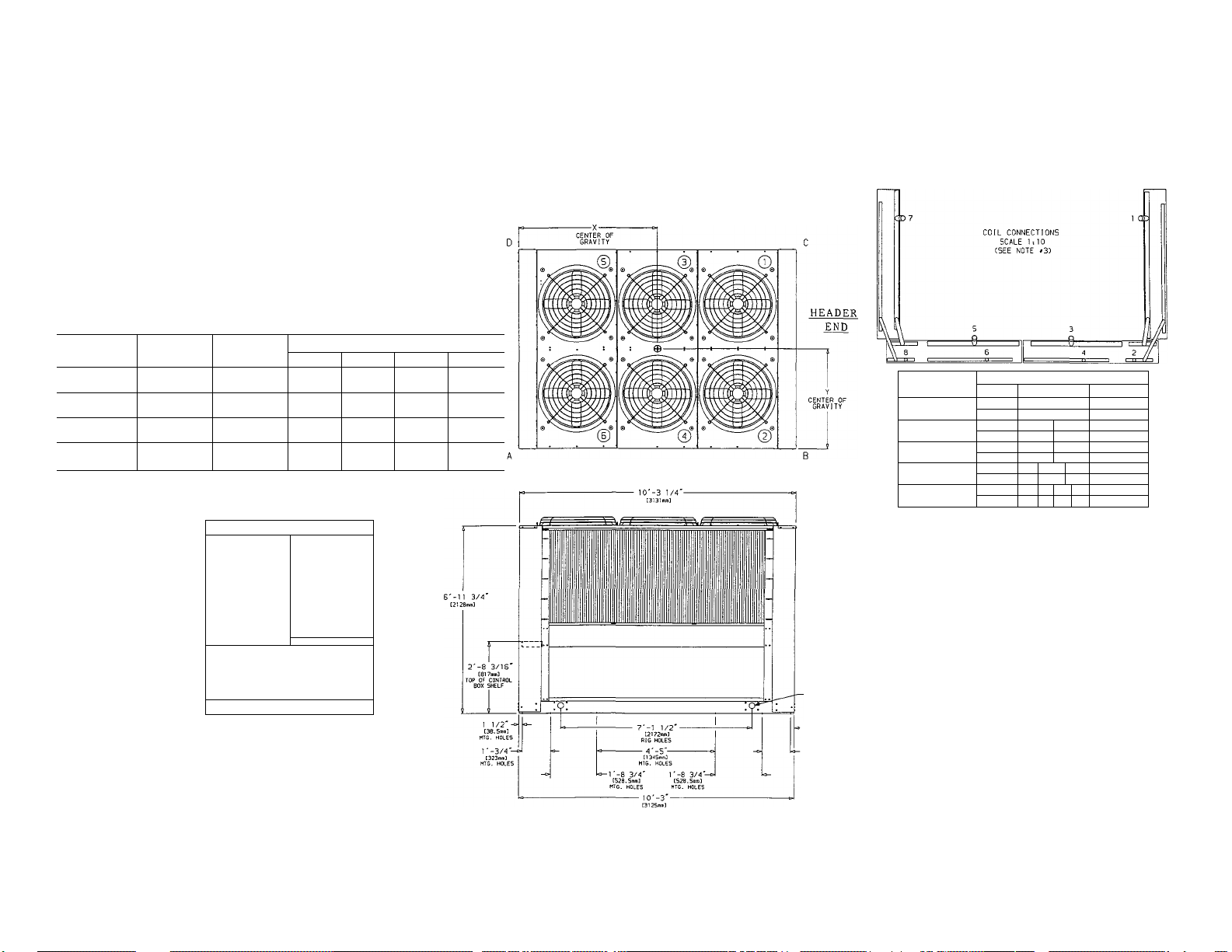
NOTES:
1. The approximate operating weight of the unit is;
09DK-074—
09DK-074-C
09DK-084
09DK-084-C
2. Unit must have clearances for airflow as follows:
Top — Do not restrict in any way.
Ends — 5 ft [1524 mm]
Sides — 6 ft [1829 mm]
3. All units are shipped with a capacity split tubing kit. This kit may be used by
the field to obtain 100%, 50%/50% and 67%/33% capacity splits. To obtain
a 33%/33%/33% capacity split, coils must be manifolded by the field. Coils
are factory circuited for a 33%/33%/17%/17% capacity split.
UNIT
09DK-074—
09DK-074-C
09DK-084—
09DK-084-C
_________
------------
----------------
--------------
DIMENSION
3'-6 1/2"
[1080 mm]
3'-6 13/16"
[1087 mm]
3'-6 5/8"
[1082 mm]
[1092 mm]
2200 ib [998 kg]
»• 2617 Ib [1187 kg]
»■ 2421 Ib [1098 kg]
»-3099 Ib [1406 kg]
Y
3'-7"
DIMENSION
4'-8 11/16"
[1440 mm]
4'-9 3/8"
[1458 mm]
4'-9 1/8"
[1450 mm]
4'-10 1/8"
[1476 mm]
X
A
618 Ib
[280 kg]
722 Ib
[328 kg]
673 Ib
[305 kg]
843 Ib
[382 kg]
HINGED ACCESS '
■ (CONTROL BOX)
PANEL
В
526 lb
[239 kg]
630 Ib
[286 kg]
581 Ib
[264 kg]
751 Ib
[34J kg]
C
486 Ib
[220 kg]
589 Ib
[267 kg]
541 Ib
[245 kg]
709 Ib
[322 kg]
OPERATING CORNER WEIGHTS
D
571 Ib
[259 kg]
675 Ib
[306 kg]
626 Ib
[284 kg]
796 Ib
[361 kg]
CAPACITY SPLIT
100%
50%/50%
67%/33%
33%/33%/33%
ЗЗУ^/ЗЗУ./^7%/^7У.
CONNECTIONS
TYPE
HOT GAS 1,3,5.7
LIQUID
HOT GAS
LIQUID 2.4
HOT GAS
LIQUID 2,4.5
HOT GAS 1
LIQUID 2 8
HOT GAS 1 7
LIQUID 2 8
NO.S
2,4,5,8
1,3 5.7
1,3.5 7
7
SIZE
1 3/8' I.D.
7/8 I.D.
1 3/8' I.D.
6.8 7/8 I.D.
1 3/8' I.D.
6 7/8 I.D.
3.5 1 3/8' I.D.
4,6 7/8 I.D.
3
5 1 3/8' I.D.
4
S 7/8 I.D.
Cl6) MTG HOLES
17/32' DIA.-^
1 '-A 7/8'-
[428.5лул]
MTG. HOLES
1 '-5 1/2'-
[444min]
MTG. HOLES
1 -4 3/4 -
t425mml
MTG. HOLES
T
1 1 .
---------------------
1 ’
-Г-5 1/2'
C444mm]
MTG. MOLES
0-1 1/2'
CSa.Smol
MTG. HOLES
r 7/8'
[428.5n<ml
,MTG. HOLES
BASE OVERALL
Fig. 3 — Dimensions; 074 and 084 Units
(4i RIG HOLES
2 5/8' DM.
C67mm}
-r-6 3/4'
C476.Snm3
RIG HOLES
-1 '-3/4'
[323>niti]
MTG. HOLES
7'-4 1/2'
12247mm)
BASE OVERALL
Page 7
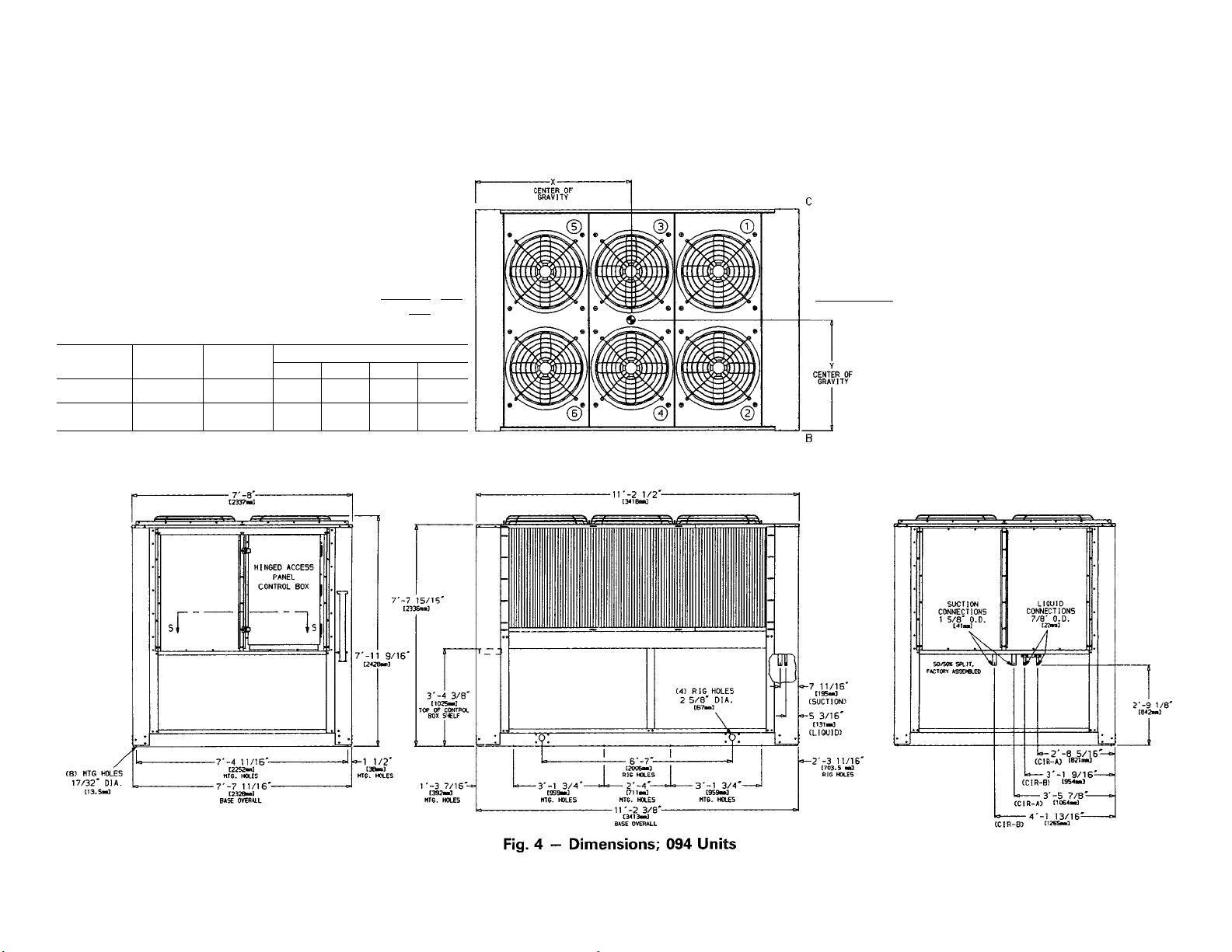
NOTES.
1. The approximate operating weight of the unit is:
09DK-094
----------------
09DK-094-C
2. Unit must have clearances for airflow as follows:
Top — Do not restrict in any way.
Ends — 5 ft [1524 mm]
Sides — 6 ft [1829 mm]
3. Mounting holes may be used to mount unit to concrete pad. They are not
recommended for mounting unit to spring isolators. If spring isolators are
used, a perimeter support channel between the unit and the isolators is
recommended.
-------------
». 2850 lb [1294 kg]
»3560 lb [1615 kg]
CONTROL
END
BOX
HEADER END
UNIT
09DK-094—
09DK-094-C
DIMENSION
Y X
5’-2 7/8"
[1597 mm]
5'-2 7/8"
[1597 mm]
DIMENSION
3'-9 3/16"
[1148 mm]
3'-9 3/16"
[1148 mm]
OPERATING CORNER WEIGHTS
A
769 lb
[349 kg]
960 lb
[436 kg]
B C
676 lb
[307 kg]
845 lb
[383 kg]
658 lb
[299 kg]
821 lb
[372 kg]
[339 kg]
[424 kg]
D
747 lb
934 lb
Page 8

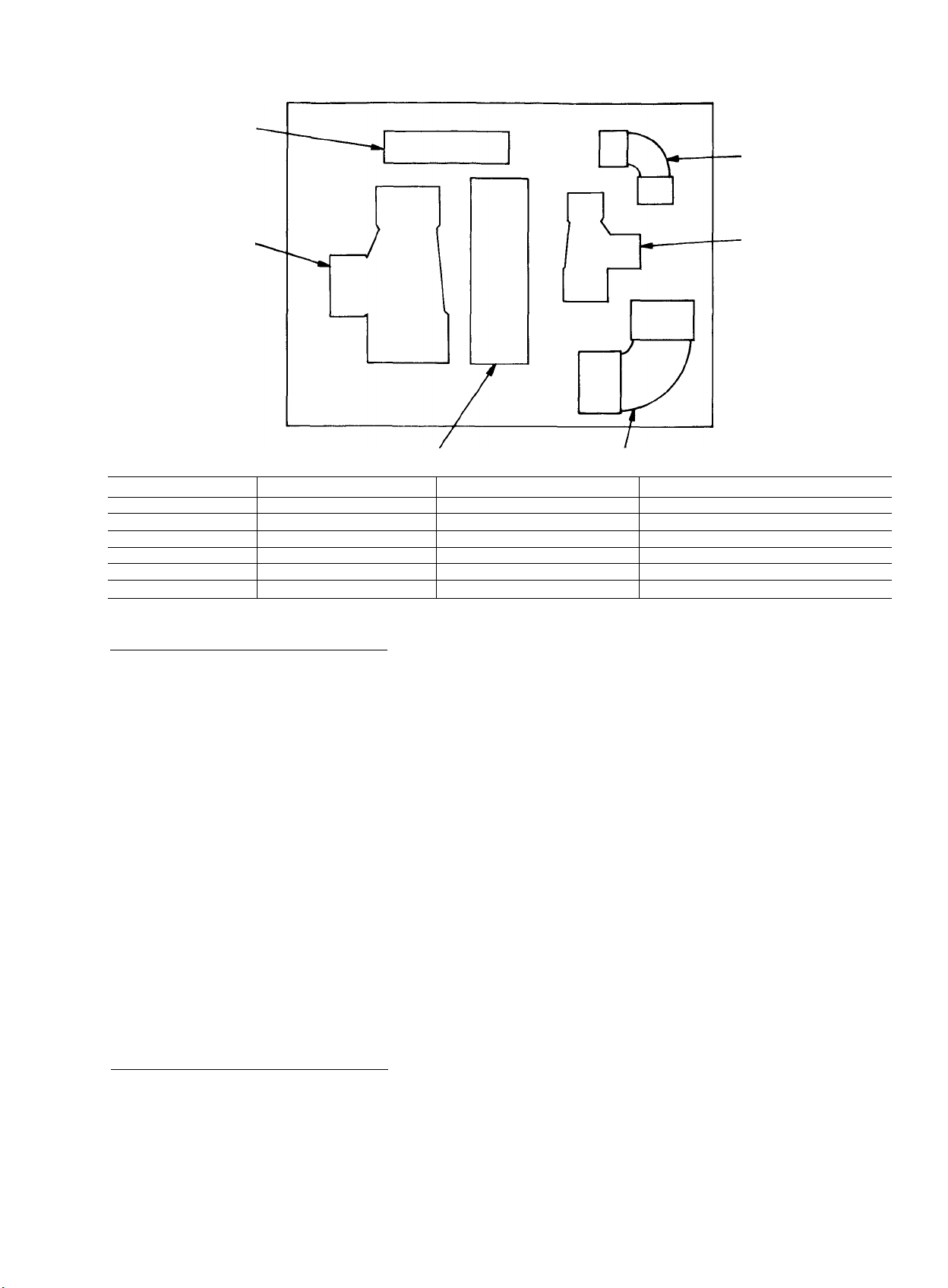
TUBING PACKAGE INSTALLATION - Before install
ing, inspect the package contents. If any parts are missing
or damaged, file a claim with the shipping company and
notify your Carrier representative
conduit (Greenfield conduit recommended) is required
according to UL/CSA (Underwriters’ Laboratories/
Canadian Standards Association) code for the FCPS field
wiring. Field supplied 3/8-in. conduit connectors are re
quired for connection to the junction box.
100% Coil Circuiting Applications: 054, 064 Units
/. Piping — Refer to Fig. 10 and 14 for field piping de
tails for 100% coil circuiting. Note that tubes 15 and 22 re
quire cuts on the longer legs of the tubes Two 7/8-in. OD
tubes, approximately 3 in. (76.2 mm) long, must be cut
from the remaining tubes (tubes 21, 23, or 25) and brazed
between the tees (item 8) and coil header stubs. The re
maining tubes are not used in this application and may be
discarded.
2. Install Fan Cycle Pressure Switches and Clamps — Braze 2
valve core bodies (item 5) to designated hole locations on
tubes 19 and 22. Insert valve cores (item 6), into valve core
bodies by threading into place and tightening to 1.5 to
3 in.-lb (169.5 to 339 mN-m). Install FCPSl and FCPS2
(item 7) at designated locations on tubes 19 and 22. Cut
the 3/8-in. field-supplied FCPS conduit to fit between each
FCPS location and the junction box on the unit. Figure 13
shows a typical installation of the conduit. Feed FCPS wires
through each conduit and secure at the switch using each
conduit connector. See Fig. 15. Secure the conduit at the
Junction box with 3/8-in. field-supplied conduit connectors.
Wire FCPSl and FCPS2 according to Fig. 16. Clamp hot
gas line, tube 27, at the location specified in Fig. 14 using
the 1 5/8-in. clamp (item 4) and the 2 screws supplied. Clamp
the liquid line, tube 24, using the 1 1/8-in. clamp (item 2)
and the 2 screws provided.
50/50% Coil Circuiting Applications: 054 and 064 units
1. Piping — Refer to Fig. 10 and 17 for field piping de
tails for 50/50% coil circuiting. Note that tubes 21 and 22
require cuts on the longer legs of the tubes. Two 7/8-in.
OD tubes, approximately 3 in (72.6 mm) long, must be
cut from the remaining tubes (21,25, 26, or 29) and brazed
between the tees (item 8) and coil header stubs. The re
maining tubes are not used in this application and may be
discarded.
2. Install Fan Cycle Pressure Switches and Clamps — Braze 2
valve core bodies (item 5) to designated hole locations on
tubes 19 and 22 Insert valve cores (item 6) into valve core
bodies by threading into place and tightening to 1.5 to
3 in.-lb (169.5 to 339 mN-m). Install FCPSl and FCPS2
(item 7) at designated locations on tubes 19 and 22. Cut the
field-supplied 3/8-in. FCPS conduit to fit between each FCPS
location and the junction box on the unit. Figure 13 shows
a typical installation of the conduit. Feed FCPS wires through
each conduit and secure at the switch using each conduit
connector. See Fig. 15. Secure the conduit at the junc
tion box with 3/8-in. field-supplied conduit connectors. Wire
FCPSl and FCPS2 according to Fig. 16. Clamp hot gas
lines, tube 15, at the location specified in Fig. 17 using the
two 1 3/8-in. clamps (item 3) and 4 screws provided. Clamp
the liquid lines, tubes 21 and 23, using the two 7/8-in. clamps
(item 1) and the 4 screws provided.
A field supplied 3/8-in.
66/34% Coil Circuiting Applications: 054 and 064 Units
NOTE: To operate the 054 and 064 condenser units with
66/34% coil circuiting, an accessory fan control kit is
required. Refer to fan control kit installation instruc
tions for more information.
1. Piping — Refer to Fig. 10 and 18 for field piping de
tails for 66/34% coil circuiting. Note that tube 16 requires
cuts on the longer leg of the tube. Tube 16 is used in the
two specified locations. A 7/8-in. OD tube, approximately
3 in. (72.6 mm) long, must be cut from the remaining tubes
(23 or 26) and brazed between the tee (item 8) and coil
header stub. The remaining tubes are not used in this ap
plication and may be discarded
2. Install Fan-Cycle Pressure Switches and Clamps — Braze 3
valve core bodies (item 5) to designated hole locations on
tubes 19, 21, and 22. Insert valve cores (item 6) into valve
core bodies by threading into place and tightening to 1.5 to
3 in.-lb (169.5 to 339 mN-m). Note that the accessory fan
control kit is required for this coil circuiting. An extra FCPS
and valve assembly is provided with the kit. Install FCPSl,
FCPS2, and FCPS4 (item 7) at designated locations on tubes
19, 21, and 22. Cut the field-supplied 3/8-in. FCPS conduit
to fit between each FCPS location and the junction box on
the unit. See Fig. 13 for typical conduit installation. Feed
FCPS wires through each conduit and secure at the switch
using each conduit connector. See Fig. 15 Secure the con
duit at the junction box with 3/8-in., field-supplied conduit
connectors. Wire FCPSl, FCPS2, and FCPS4 according to
Fig. 16. Note that FCPS2 and FCPS4 are wired in parallel.
Fan 4 is shared by the 34% and 66% refrigeration circuit;
the fan switches on if either circuit requires it. At the loca
tion specified in Fig. 18, clamp hot gas lines, tubes 15 and
30, using a 1 3/8-in. clamp (item 3) and a 1 1/8-in. clamp
(item 2) with the 4 screws supplied. Clamp the liquid lines,
tubes 21 and 25, with 7/8-in. clamps (item 1) and 4 screws
provided.
100% Coil Circuiting Applications; 074 Units
1 Piping — Refer to Fig. 10 and 19 for field piping
details for 100% coil circuiting. Note that tube 16 requires
a cut on the longer leg of the tube. Two 7/8-in. OD tubes
approximately 3 in. (72.6 mm) long, must be cut from
the remaining tubes (22 or 23) and brazed between the tees
(item 9) and coil header stubs. The remaining tubes are not
used and may be discarded.
2 Install Fan Cycle Pressure Switches and Clamps — Braze 2
valve core bodies (item 6) to designated hole locations on
tubes 20 and 24. Insert valve cores (item 7) into valve core
bodies by threading into place and tightening to 1.5 to
3 in.-lb (169 to 339 mN-m). Install FCPSl and FCPS2
(item 8) at designated locations on tubes 20 and 24. Cut the
3/8-in. field-supplied FCPS conduit to fit between each FCPS
location and the junction box on the unit. See Fig. 13 for
typical conduit installation. Feed FCPS wires through each
conduit and secure at the switch using each conduit con
nector. See Fig. 15. Secure the conduit at the junction
box with 3/8-in. field-supplied conduit connectors. Wire
FCPSl and FCPS2 according to Fig. 20. Clamp hot gas
line, tube 28, using 2 1/8-in. clamp (item 5) at the location
specified in Fig. 19 with the 2 screws supplied. Clamp the
liquid line, tube 25, using 1 1/8-in. clamp (item 2) and the
2 screws provided.
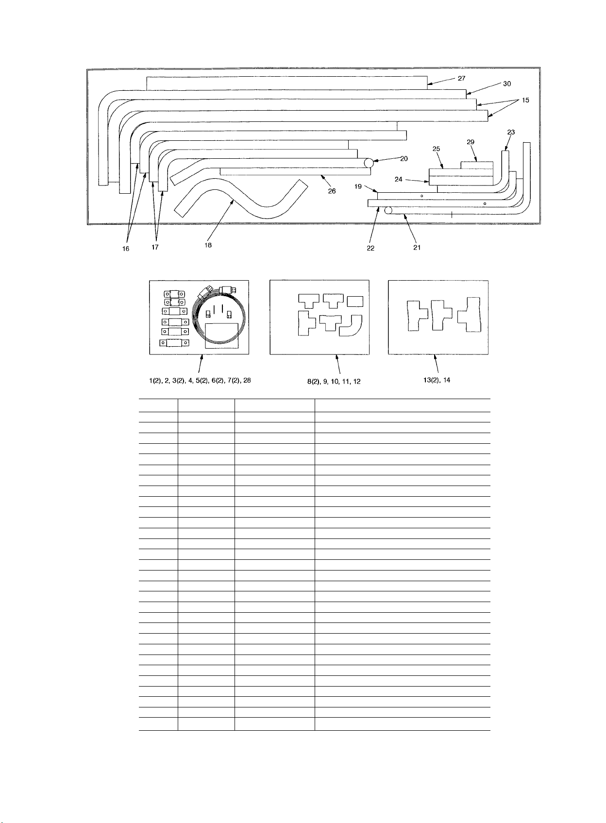
Page 9
#
I
ITEM
10
11
12
13
14 1
15
16
17
18
19
20
21
22
23
24 1
25
26
27 1
28
29
30
QUANTITY
1
2 1 Tube Clamp
3
4
5
6
7
8
9
2 Tube Clamp 7/8 in.
2 Tube Clamp
1 Tube Clamp
2 Valve Body
2 Valve Core
2 Switch
2 Tee
1 Tee
1 Tee
1 Solder Coupling
1 Elbow, 90 Degree 1 1/8 in
2 Tee
Tee
2
2
2
1
1
1
1 Liquid Tube
1
1
1
1
8
1
1
Discharge Tube
Discharge Tube
Discharge Tube 1 1/8 in. CD X 24 5/32 in L x 5 1/16 in W
Discharge Tube 1 3/8 in. CD
Liquid Tube
Discharge Tube
Liquid Tube
Liquid Tube
Straight Tube
Straight Tube
Straight Tube
Straight Tube
Screw
Straight Tube
Discharge Tube
NAME
DESCRIPTION
1 1/8 in.
1 3/8 in.
1 5/8 in.
1/4 in. male flare fitting
-
Fan cycle pressure switch
7/8 in. X 7/8 in X 7/8 in.
1 1/8 in. X 1 1/8 in. X 1 1/8 in.
7/8 in. X 7/8 in. X 1 1/8 in
1 1/8 in.
1 3/8 in. X 1 1/8 in. X 1 1/8 in
1 5/8 in X 1 3/8 in. X 1 3/8 in.
1 3/8 in. CD X 44 23/32 in L x 10 1/16 in. W
1 1/8 in. CD X 32 11/32 in L X 5 1/16 in. W
7/8 in CD X 16 13/16 in. L X 3 7/16 in. W
1 1/8 in. ODx 24 1/2 in. L
7/8 in. CD X 17 11/16 in L
7/8 in. CD X 18 13/16 in Lx 3 7/16 in. W
7/8 in CD x8 11/16in. Lx5 1/16in. W
1 1/8 in. ODx 7 3/4 in L
7/8 in. CD X 7 3/4 in. L
7/8 in. CD X 18 1/4 in. L
1 5/8 in. OD X 34 in. L
1/4-14x5/8 in. long
7/8 in. OD X 3 7/8 in long
1 1/8 in. OD X 44 19/32 in. L x 11 9/16 in. W
Fig. 5 - 09DK054,064 Tubing Package Contents
Page 10
16
ITEM QUANTITY
1
2
2 1
3
1
4 2
5 1
6
2
7 2
8 2
9
10
2
1
NAME
Tube Clamp
Tube Clamp
Tube Clamp
Tube Clamp
Tube Clamp
Valve Body
Valve Core
Switch Fan cycle pressure switch
Tee
Coupling
11 1 Tee
12
13 2
14
15 1
16 2
1
1
Tee
Tee
Tee
Discharge Tube 1 3/8 in. CD X 50 25/32 in. L x 14 1/8 in. W
Discharge Tube 1 5/8 in. OD X 50 29/32 in. L x 12 1/16 in. W
17 2 Discharge Tube
18
19 1
2 Discharge Tube 1 3/8 in. OD X 19 7/8 in. L x 4 3/4 in. W
Discharge Tube 1 5/8 in. OD
20 1 Liquid Tube
21 1 Discharge Tube
22 1 Liquid Tube
23
24 1
25 1
26 1
27
28 1
29 8
1 Liquid Tube
Liquid Tube 7/8 in. OD X 14 13/16 in. L X 3 7/16 in. W
Straight Tube 1 1/8 in. ODx7 3/4in. L
Straight Tube 7/8 in. OD X 8 1/4 in. L
1
Straight Tube
Straight Tube 2 1/8 in. OD X 40 in. L
Screw 1/4 in.-14 X 5/8 in. long
DESCRIPTION
7/8 in.
1 1/8 in.
1 3/8 in
1 5/8 in.
2 1/8 in.
1/4 in. maie flare fitting
-
7/8 in. X 7/8 in. X 7/8 in
1 3/8 in. X 1 3/8 in
7/8 in. X 7/8 in X 1 1/8 in
1 3/8 in. X 1 3/8 in. X 1 3/8 in.
1 5/8 in X 1 3/8 in. X 1 3/8 in.
. 2 1/8 in. X 1 5/8 in. X 1 5/8 in.
1 3/8 in. OD X 34 1/2 in. L X 4 3/4 in. W
7/8 in OD X 23 13/16 in. L X 3 7/16 in. W
1 3/8 in. OD X 28 3/8 in. L
7/8 in. OD X 23 1/4 in. L (074 Units only)
7/8 in. OD X 18 1/4 in. L
7/8 in. OD X 17 7/8 in. L
Fig. 6 - 09DK074,084 Tubing Package Contents
10
Page 11
#
I
ITEM
1
2
3
4
5
6
50/50% Coil Circuiting Applications: 074 Units
1. Piping — Refer to Fig. 10 and 21 for field piping de
tails for 50/50% coil circuiting. Note that tube 23 requires a
cut, located exactly at the location of the hole in the tube.
Tube 23 is used in the two locations specified. Two 7/8-in.
OD tubes, approximately 3 in. (72.6 mm) long, must be
cut from the remaining tubes (22, 26, or 27) and brazed be
tween the tees (item 9) and coil header stubs. The remain
ing tubes are not used in this application and may be dis
carded.
2, Install Fan Cycle Pressure Switches and Clamps — Braze 2
valve core bodies (item 6) to designated hole locations on
tubes 20 and 24. Insert valve cores (item 7) into valve core
bodies by threading into place and tightening to 1.5 to
3 in.-lb (169.5 to 339 mN-m). Install FCPSl and FCPS2
(item 8) at designated location on tubes 20 and 24. Cut the
3/8-in. field-supplied FCPS conduit to fit between each FCPS
location and the junction box on the unit. See Fig. 13 for
typical conduit installation. Feed FCPS wires through each
conduit and secure at the switch using each conduit con
nector. See Fig. 15. Secure the conduit at the junction box
with 3/8-in. field-supplied conduit connectors. Wire FCPSl
and FCPS2 according to Fig. 20. Clamp hot gas line, tube
16, at the location specified in Fig. 21 using two 1 5/8-in.
clamps (item 4) and 4 screws supplied. Clamp the liquid
lines, tube 23, using the two 7/8-in. clamps (item 1) and
the 4 screws provided.
68/32% Coil Circuiting Applications: 074 Units
NOTE: To operate the 074 condenser units with 68/32%
coil circuiting, an accessory fan controi kit is re
quired. See accessory installation instructions for more
information.
QUANTITY
1
1 Tee 2Va in. X iya in X 1% in
1 Discharge Tube 1% in. OD X 5V4 in. L
1 Elbow % in. X % in.
1
1 Elbow 1% in. X iys in
Fig. 7 — 09DK094 Tubing Package Contents
NAME
Liquid Tube % in. X 3V2 in. L
Tee IVsin X % in X Vs in.
1. Piping — Refer to Fig. 10 and 22 for field piping de
tails for 68/32% coil circuiting. Note that tubes 17 and 20
require cuts on the longer legs of the tubes. Tube 17 is used
in the two locations specified. Also, a 7/8-in. OD tube, ap
proximately 3 in. (72.6 mm) long, must be cut from the
remaining tubes (23 or 27) and brazed between the tee (item
9) and coil header stub. The remaining tubes are not used
in this application and may be discarded.
2. Install Fan Cycle Pressure Switches and Clamps — Braze 3
core bodies (item 6) to designated hole locations on tubes
20, 22, and 24. Insert valve cores (item 7) into valve core
bodies by threading into place and tightening to 1.5 to
3 in.-lb (169.5 to 339 mN-m). Note that the accessory fan
control kit is required for this coil circuiting. An extra FCPS
and valve assembly is provided with the kit. Install FCPSl,
FCPS2, and FCPS4 (item 8) at designated locations on tubes
20, 22, and 24. Cut the 3/8-in. field-supplied FCPS conduit
to fit between each FCPS location and the junction box on
the unit. See Fig. 13 for typical conduit installation. Feed
FCPS wires through each conduit and secure at the switch
using each conduit connector. See Fig. 15. Secure the con
duit at the junction box with 3/8-in. field-supplied conduit
connectors. Wire FCPSl, FCPS2 and FCPS4 according to
Fig. 20. Note that FCPS2 and FCPS4 are wired in parallel.
Fan 4 is shared by the 32% and 68% refrigeration circuit;
the fan switches on if either circuit requires it. At the loca
tion specified in Fig. 22, clamp hot gas lines, tube 15 with
a 1 3/8 in. clamp (item 3) and tube 16 with a 1 5/8 in.
clamp (item 4) with the 4 screws supplied. Clamp the liq
uid lines, tube 22, with a 7/8 in. clamp (item 1) and tube 25
with a 1 1/8 in. clamp (item 2) with the 4 screws supplied.
DESCRIPTION
11
Page 12

COMPRESSORS
SEE NOTE 1
09DK084 UNIT (LOCATED ABOVE OTHER COMPONENTS)
PRESSURE RELIEF DEVICES*
FILTER-DRIERS*
SEE NOTE 4
Fig. 8 — Typical Piping for 09DK Condenser With a Dual Split System
‘Field supplied.
NOTES
Hot gas lines should rise above refrigerant level in con
denser circuit.
2. Trap should be installed on hot gas lines to prevent
condenser oil and refrigerant vapor migration from ac
cumulating on compressor heads during off cycle.
Pitch all horizontal lines downward in the direction of
refrigerant flow.
Refer to Carrier System Design Manual, part 3 for proper
piping sizes and design.
MOISTURE
■ INDICATORS*
(SIGHT GLASS)
SEE NOTE 4
Page 13

#
054,064 Units
FCPS2
100%
—
o
----------------------
FCPS2■
T---I —f
--------------------------------------------------
i 1 ! i
III!
1 1 1 <
1 1 1 I
III'
1 1 1 1
„I — .
ii
50% / 50%
---o--«--o
îil
I
FCPS2
34%
66%
FCPS1
FCPS1
FCPS1
FCPS2
r---0
Î
34%
FCPS — Fan Cycle Pressure Switch
FCPS2 FCPS4
Î !| Î
16% 16%
Fig. 9 — Typical Field Piping Arrangements
FCPS3
'4 4
34%
13
response to condensing pressure.
FCPS2 = Fan cycle pressure switch 2 cycles fan 4 In
response to condensing pressure.
FCPS3 = Fan cycle pressure switch 3 cycies fan 3 in
response to condensing pressure.
FCPS4 = Fan cycle pressure switch 4 cycles fan 4 in
response to condensing pressure
In the above applications where a fan is being shared by two
different refrigeration circuits, the FCPSs (FCPS1 and 3 or
FCPS2 and 4) are in parallel so that the fan switches on in
response to the condensing pressure in either circuit
FCPS1
Fan cycle pressure switch 1 cycles fan 3 in
Page 14

O-
............
074 Units
...........
O
FCPS2■
FCPS2■
FCPS2■
O
---------
-11
Ti....
9
32%
"f—1
n
fel-
V
1 FCPS4
ii
50% / 50%
1
_______
100%
it ij
itii
68%
i 1
—0 —
FCPS1
FCPS1
FCPS1
O
FCPS2■
--0
t 1
32%
FCPS — Fan Cycie Pressure Switch
--
O
FCPS3
32%
-O
O- -
FCPS1
NOTES:
1. FCPS1 = Fan cycle pressure switch 1 cycles fan 3 in
response to condensing pressure.
2. FCPS2 = Fan cycle pressure switch 2 cycles fan 4 in
response to condensing pressure.
3 FCPS3 = Fan cycle pressure switch 3 cycles fan 3 in
response to condensing pressure.
4 FCPS4 = Fan cycle pressure switch 4 cycles fan 4 in
response to condensing pressure.
5 In the above applications where a fan is being shared by two
different refrigeration circuits, the FCPSs (FCPS1 and 3 or
FCPS2 and 4) are in paraliel so that the fan switches on in
response to the condensing pressure in either circuit.
--------
’11
32%
FCPS2
1
FCPS4
o-J-w
t il It
FCPS4
----
36%
FCPS3
1-*
1-0
__
s.
__
!l
18%
Fig. 9 — Typical Field Piping Arrangements (cent)
18%
32%
14
FCPS1
Page 15

I
084 Units
FCPS2•
FCPS2■
o
-
.........
n
_____
O
o--‘
O---------1
-f—"f-—f"
1 1 1
1 1 1
1 1 1
1 1 1
1 1 I
1 1 1
1 1 1
1 1 1
1 1
100%
"f—!
50% / 50%
...................
..C.
i i
it il
o
FCPS1
FCPS1
FCPS2-
FCPS2
--0
*11
9
33%
FCPS2
1--------
feri-
V
1 FCPS4
r-O
FCPS4
I I
Î4
it il
67%
FCPS3
O-
FCPS1
1. FCPS1 = Fan cycle pressure switch 1 cycles fan 3 In
response to condensing pressure.
2 FCPS2 = Fan cycle pressure switch 2 cycles fan 4 in
response to condensing pressure
3. FCPS3 = Fan cycle pressure switch 3 cycles fan 3 in
response to condensing pressure
4 FCPS4 = Fan cycle pressure switch 4 cycles fan 4 in
response to condensing pressure.
5. In the above applications where a fan is being shared by two
different refrigeration circuits, the FCPSs (FCPS1 and 3 or
FCPS2 and 4) are in parallel so that the fan switches on in
response to the condensing pressure in either circuit.
î '1
33%
FCPS — Fan Cycle Pressure Switch
FCPS1
t ¡1 !l
17%
Fig. 9 - Typical Field Piping Arrangements (cent)
17%
33%
15
Page 16

FCPS2
094 Units
NOTES:
1 FCPS1 Fan cycle pressure switch 1 cycles fan 3
FCPS2 = Fan cycle pressure switch 2 cycles fan 4
Fig. 9 — Typical Field Piping Arrangements (cont)
in response to condensing pressure.
in response to condensing pressure
100% Coil Circuiting Applications: 084 Units
1. Piping — Refer to Fig. 10 and 23 for field piping de
tails for 100% coil circuiting. Note that tubes 16 and 20 re
quire cuts on the longer legs of the tubes. Two 7/8-in. OD
tubes, approximately 3 in (72.6 mm) long, must be cut
from the remaining tubes (22 or 23) and brazed between the
tees (item 9) and coil header stubs. The remaining tubes are
not used in this application and may be discarded.
2. Install Fan Cycle Pressure Switches and Clamps — Braze 2
valve core bodies to designated hole locations on tubes 20
and 24. Insert valve cores into valve core bodies by thread
ing into place and tightening to 1.5 to 3 in.-lb (169.5 to
339 mN-m). Install FCPSl and FCPS2 at designated loca
tions on tubes 20 and 24. Cut the 3/8-in. field-supplied FCPS
conduit to fit between each FCPS location and the junction
box on the unit. See Fig. 13 for typical conduit installation.
Feed FCPS wires through each conduit and secure at the
switch using each conduit connector See Fig. 15. Secure
the conduit at the junction box with 3/8-in. field-supplied
conduit connectors. Wire FCPSl and FCPS2 according to
Fig 20. At the location specified in Fig. 23, clamp hot gas
line, tube 28, using 2 1/8-in. clamp and 2 screws provided.
Clamp the liquid line, tube 25, using 1 1/8-in. clamp and
2 screws provided.
50/50% Coil Circuiting Applications: 084 Units
1 Piping — Refer to Fig. 10 and 24 for field piping de
tails for 50/50% coil circuiting. Note that tube 20 requires a
cut on the longer leg of the tube. Tube 23 requires a cut
located exactly at the location of the hole in the tube, and is
used at the two locations specified. Two 7/8-in. OD tubes,
approximately 3 in. (72.6 mm) long, must be cut from the
remaining tubes (22, 26, and 27) and brazed between the
tees (item 9) and coil header stubs. The remaining tubes are
not used in this application and may be discarded.
2. Install Fan Cycle Pressure Switches and Clamps — Braze 2
valve core bodies (item 6) to designated hole locations on
tubes 20 and 24. Insert valve cores (item 7) into valve core
bodies by threading into place and tightening to 1.5 to
3 in.-lb (169.5 to 339 mN-m). Install FCPSl and FCPS2
(item 8) at designated locations on tubes 20 and 24. Cut the
3/8-in field-supplied FCPS conduit to fit between each FCPS
location and the junction box on the unit. See Fig. 13 for
typical conduit installation. Feed FCPS wires through each
conduit and secure at the switch using each conduit con
nector See Fig. 15. Secure the conduit at the junction box
with 3/8-in. field-supplied conduit connectors. Wire FCPSl
and FCPS2 according to Fig. 20. At the location specified
in Fig. 24, clamp hot gas line, tube 16, using two 1 5/8-in.
clamps and 4 screws provided. Clamp the liquid lines, tubes
23, using two 7/8-in. clamps (item 1) and 4 screws
provided.
16
Page 17

#
LEFTSIDE COILS
RIGHT SIDE COILS
054,064
PERCENT CAPACITY
SPLIT
34/34/16/16
•Connection sizes reflect size of each coll header nozzle
tA tubing package is factory supplied to facilitate field piping installation for the 100, 50/50 and 66/34% capacity split applications See Fig 5
LINE TYPE
Hot Gas 1,3,5,7 1 1/8
Liquid 2,4,6,8 7/8
Hot Gas 1,3/5,7 1 1/8
Liquid 2,4/6,8 7/8
Hot Gas
Liquid
Hot Gas 1/7/3,5 1 1/8
Liquid
Hot Gas
Liquid
COIL CONNECTION
NUMBER
1,3,5/7 1 1/8 1 3/8 1 1/8
2,4,6/8 7/8 7/8 7/8
2/8/4,6 7/8 (3) 7/8
1/7/3/5
2/8/4/6
COIL CONNECTION
in.-ODM*
1 1/8
7/8
074
PERCENT CAPACITY
SPLIT
32/32/18/18
•Connection sizes reflect size of each coil header nozzle
tA tubing package is factory supplied to facilitate field piping installation for the 100, 50/50 and 68/32% capacity split applications. See Fig 6.
LINE TYPE
Hot Gas 1,3,5,7 1 3/8
Liquid 2,4,6,8 7/8
Hot Gas
Liquid
Hot Gas 1,3,5/7 1 3/8 1 5/8
Liquid 2,4,6/8 7/8 7/8
Hot Gas 1/7/3,5 1 3/8
Liquid
Hot Gas
Liquid
COIL CONNECTION
NUMBER
1,3/5,7 1 3/8 1 5/8
2,4/6,8 7/8 7/8
2/8/4,6
1/7/3/5
2/8/4/6
COIL CONNECTION
in.-ODM*
7/8
1 3/8
7/8
084
PERCENT CAPACITY
SPLIT
50/50
33/33/17/17
•Connection sizes reflect size of each coil header nozzle
fA tubing package is factory supplied to facilitate field piping installation for the 100, 50/50 and 67/33% capacity split applications See Fig 6
LINE TYPE
Hot Gas
Liquid
Hot Gas
Liquid
Hot Gas
Liquid
Hot Gas
Liquid
Hot Gas
Liquid
COIL CONNECTION
NUMBER
1,3,5,7 1 3/8 2 1/8
2,4,6,8
1,3/5,7 1 3/8 1 5/8 1 5/8
2,4/6,8
1,3,5/7
2,4,6/8
1/7/3,5
2/8/4,6
1/7/3/5
2/8/4/6
COIL CONNECTION
in.-ODM*
7/8
7/8
1 3/8 1 5/8 1 3/8
7/8 1 1/8 7/8
1 3/8 (3) 1 3/8
7/8
1 3/8
7/8
TUBING CONNECTION
in. ODMf
1 5/8
1 3/8 1 3/8
7/8 7/8
TUBING CONNECTION
TUBING CONNECTION
7/8 7/8
1 1/8
1/8
(3)
in.-ODMt
2 1/8
1 1/8
(3) 1 3/8
(3) 7/8
In.-ODMt
1 1/8
(3) 7/8
1 5/8
7/8
1 3/8
7/8
Fig. 10 — Coil Connection Data, 09DK054-084
17
Page 18

PERCENT CAPACITY
SPLIT
100
50/50
'Connection sizes reflect size of each coii header nozzie.
tA tubing package is factory supplied to facilitate fieid piping instaiiation for 100% capacity spiit appiications. See Fig 7.
LINE TYPE
Hot Gas
Liquid
Hot Gas
Liquid
COIL CONNECTION
NUMBER in. - ODM*
1,3,5,7
2,4,6,8 % IVa
1,3/5,7
2,4/6,8 ye Ve/ye
COIL CONNECTION
1% 2Vb
1%
TUBING CONNECTION
Fig. 11 - Coil Connection Data, 09DK094
in. - ODMt
IVe/iya
iwwflWSlIW.
_ _ _ _
CONDUITS
-
_ _ _ _ _ _ _ __ _ _ _ _ _ _ _ _ _
Fig. 13 — Typical Coil Circuiting for 09DK054-094
Units (67/33% Split Option; 084 Unit Shown)
Fig. 12 — Typical Factory-Supplied Coil Circuiting,
09DK054-094 Units (084 Shown)
18
Page 19

61l?>3% Coil Circuiting Applications: 084 Units
NOTE: To operate 084 condenser units with 67/33% coil
circuiting, an accessory fan control kit is required.
See accessory installation instructions for more
information.
7. Piping — Refer to Fig. 10 and 25 for field piping de
tails for 67/33% coil circuiting. Note that tubes 17 and 20
require cuts on the longer legs of the tubes. Tube 17 is used
in the two locations specified. Also, a 7/8-in. OD tube, ap
proximately 3 in. (72.6 mm) long must be cut from the re
maining tubes (22 or 27) and brazed between the tee
(item 9) and coil header stub. The remaining tubes are not
used in this application and may be discarded.
2. Install Fan Cycle Pressure Switches and Clamps — Braze 3
valve core bodies (item 6) to designated hole locations on
tubes 20, 23, and 24. Insert valve cores (item 7) into valve
core bodies by threading into place and tightening to 1.5 to
3 in.-lb (169.5 to 339 mN-m). Note that the accessory
fan control kit is required for this coil circuiting. An extra
FCPS and valve assembly is provided with the kit. Install
FCPSl, FCPS2, and FCPS4 (item 8) at designated loca
tions on tubes 20, 23, and 24. Cut the 3/8-in. field-supplied
FCPS conduit to fit between each FCPS location and the
junction box on the unit. See Fig. 13 for typical conduit
installation. Feed FCPS wires through each conduit and
secure at the switch using each conduit connector. See
Fig. 15. Secure the conduit at the junction box with 3/8-in.
field-supplied conduit connector. Wire FCPS 1, FCPS2, and
FCPS4 according to Fig. 20. Note that FCPS2 and FCPS4
are wired in parallel. Fan 4 is shared by the 33% and 67%
refrigeration circuit; the fan switches on if either circuit re
quires it. At the location specified in Fig 25, clamp hot gas
lines, tube 15 with a 1 3/8-in. clamp (item 3) and tube 16
with a 1 5/8-in. clamp (item 4) with the 4 screws supplied.
Clamp the liquid lines, tube 23 with a 7/8-in. clamp
(item 1) and tube 25 with a 1 1/8-in. clamp (item 2) with
4 screws supplied.
100% Coil Circuiting Applications: 094 Units
Refer to Fig. 11 and 26 for field piping details for 100%
coil circuiting Braze the tees, pipe, and elbows to mani
fold the hot gas and suction tubes as shown in Fig. 26. The
fan cycle pressure switches are factory supplied and in
stalled.
50/50% Coil Circuiting Applications: 094 Units
Unit piping and fan cycle pressure switches are factory
supplied and installed for 50/50% coil circuiting. No field
modifications to coil circuiting are required. See Fig. 11
and 27 for piping details.
THREE AND EOUR COIL SPLIT, COIL CIRCUITING
APPLICATIONS; 054-084 UNITS ONLY
NOTE: To operate 054-084 condenser units with the 3
and 4 coil split coil circuiting, the fan control kit is re
quired. See accessory installation instructions for more
information.
7. Piping — Piping is not provided in the tubing package
for these coil circuiting options. Tubing is field fabricated
and installed according to the coil circuiting shown in
Fig. 9. For pipe sizing information, refer to Refrigerant Line
Sizing, page 20. To secure the piping, it should be routed
to the brackets supplied on the unit.
100%
#
1 Dimensions in ( ) are in millimeters.
2 See Fig 5 for tubing package contents
Fig. 14 — 100% Coil Circuiting; 054 and 064 Units
19
Page 20

2. Install Fan Cycle Pressure Switches and Clamps — Four
FCPSs should be used. Locate holes, valve core assem
blies, and FCPSs 1, 2, 3, and 4 at the specified locations.
See Fig. 9. Insert valve cores into valve core bodies by
threading into place and tightening to 1.5 to 3 in.-lb (169.5
to 339 mN-m). The additional two FCPSs and valve core
assemblies are provided with the accessory fan control kit.
Cut the 3/8-in. field-supplied FCPS conduit to fit between
each FCPS location and the junction box on the unit. See
Fig. 13 for typical conduit installation. Feed FCPS wires
through each conduit and secure at the switch using each
conduit connector. See Fig. 15. Secure the conduit at the
junction box with 3/8-in. field-supplied conduit connectors
Wire the FCPSs according to Fig. 16 and 20. Note that
FCPS2 and 4 and FCPSl and 3 are wired in parallel. Fans
3 and 4 are shared by two different refrigeration circuits;
the fan switches on if either circuit requires it. Clamp all
lines to brackets supplied on the unit.
SAE — Society of Automotive Engineers
Fig. 15 — Fan Cycle Pressure Switch
REFRIGERANT LINE SIZING - Sizing depends on length
of lines between various sections of the refrigerant system.
See Fig. 10 for coil connection details. Consider the amount
of liquid lift and drop in the system as well as proper com
pressor oil return. See Liquid Lift section for more infor
mation. Consult Carrier System Design Manual, Part 3, or
Carrier E20-II Refrigerant Piping Computer Program for proper
piping sizes and design.
LIQUID SHUTOFF VALVE AND SIGHT GLASS - A
shutoff valve is not supplied with 09DK condensers. It is
strongly recommended that a full line size liquid shutoff
valve be field supplied near condenser to allow for servic
ing parts of the refrigerant circuit. A field-supplied moisture-
indicating sight glass is recommended for use in charging
and servicing the system. Refer to Fig 8.
PRESSURE RELIEF - The ASHRAE Standard 15, Safety
Code for Mechanical Refrigeration states: “Every refriger
ating system shall be protected by a pressure relief device
or some other means designed to safely relieve pressure due
to fire or other abnormal conditions.” Since 09DK con
densers do not have pressure relief devices, one must be
field supplied and installed just before the liquid line serv
ice valve. (See Fig. 8.) When the split coil is used with
multiple systems, each system must have its own pressure
relief.
REFRIGERANT RECEIVER — A refrigerant receiver is
not furnished with 09DK condensers and is not recom
mended for normal applications as its use will be detrimen
tal to the desired effects of subcooling. However, if a par
ticular application requires a receiver to increase refrigerant
holding capacity of the condenser, a receiver can be used.
Recommended receiver and valve installation and piping are
shown in Fig. 28. When a receiver is to be used yearround, it should be installed indoors.
Procedure for Using the Refrigerant Receiver — (Fig. 281
1. During normal operation — Valve A is open and valves
B and C are closed. Receiver is isolated from the
system.
2. For servicing — Valves A and C are closed and valve B
is open. Run unit until all the refrigerant is in the re
ceiver and then close valve B. Unit is now ready for ser
vicing.
3. To resume operation — Leave valve A closed and open
valves B and C. Run unit until the stored refrigerant is
drawn into the system. To completely remove the re
frigerant from the receiver, throttle valve B while noting
condition of refrigerant in the liquid line sight glass; also,
watch the suction pressure. A sudden surge of bubbles
in the sight glass and a rapid decrease in suction pres
sure indicate that all the refrigerant has been withdrawn
from the receiver Immediately close valves B and C
and then open valve A. The unit should now be ready
for normal operation, with the receiver isolated from the
system. The system should be charged to a clear sight
glass when under normal operation.
LIQUID LIFT — Amount of liquid lift available before re
frigerant flashing occurs depends on amount of liquid sub
cooling in the system
All 09DK condensers have positive subcooling when ap
plied with optimum charge. With subcooling, it is possible
to overcome an appreciable pressure drop and/or static head
(due to elevation of the liquid metering device above the
condenser).
When 09DK condensers are applied with minimum charge,
they do not provide positive subcooling. If subcooling is
required, it must be obtained by external means such as a
liquid suction interchanger.
The average amount of liquid lift available is shown in
Table 3 for refrigerants R-22, R-502, and R-134A. Avail
able subcooling is greatly reduced when R-12 and R-500
are used in these units It is recommended that the evapo
rator be at the same level as the condenser, or lower.
#
20
Page 21

MCL[> contml
POWE* simt
CSCE NOTE
Units are factory wired for a 50%/50% capacity split. If 100% capacity is required, con
nect the factory-supplied jumpers from TB2-1 to TB3-1 and from TB2-2 to TB3-2.
When a fan control kit is used, the jumper from TB2-1 to TB3-1 and from TB2-2 to TB3-2
must be connected. The fan control kit is factory wired for 67%/33% capacity split. If a
33%/33%/33% capacity split is required, remove the jumper from TB4-1 to TB5-1 and
AfU 37 » 39
from TB4-2 to TB5-2. If a 33%/33%/17%/17% capacity split is required, remove the jump
ers from TB4-1 to TB5-1 to TB7-1 and from TB4-2 to TB5-2 to TB7-2.
On fan control kits, 208/230 v units are factory wired for 230 v power supply. For 208 v
power supply, connect yellow wire to terminal marked H2.
Terminal blocks TB2, TB3, TB4, TBS, TBS and TB7 are for external field control connec
tions. Control connections are to be class 1 wiring, 14 AWG {American Wire Gage) cop
per conductors only.
5. Wiring for field power supply must be rated 75° C minimum. Use copper, copper-clad
aluminum, or aluminum conductors. Maximum incoming wire size for each terminal block
IS 2/0.
6. Replacement of factory wires must be with 105° C wire or its equivalent.
7. Factory wiring is in accordance with National Electncal Code (NEC). Field modifications
or additions must be in compliance with all applicable codes.
8. Fan motors are thermally protected. Three-phase motors are protected against primary
single phasing conditions.
9. Line numbers on the left side of the label diagrams indicate the contact number. The
numbers on the right side of label diagrams match the contacts with their corresponding
coils. A plain number indicates normally open contacts. An underlined number indicates
normally closed contacts.
Fig. 16 — Wiring Diagram and Component Arrangement; 054 and 064 Units
It c
CCNtROl KIT 0K.T)
c
CONTRO. nl ONLr)
Page 22

50 / 50%
FCPS — Fan Cycle Pressure Switch
Fig. 17 - 50/50% Coil Circuiting; 054 and 064 Units
NOTES:
1. Dimensions in ( ) are in millimeters.
2. See Fig. 5 for tubing package contents
FCPS — Fan Cycle Pressure Switch
Fig. 18 — 66/34% Coil Circuiting; 054 and 064 Units
NOTES:
1. Dimensions in ( ) are in millimeters.
2. See Fig. 5 for tubing package contents
22
Page 23

Table 3 — Available Liquid Lift, Ft (m)
REFRIGERANT
UNIT
054
064
074
084
094
NOTES:
1. The liquid lift data allows for a 7 psi (48 kpa) drop for liquid line
accessories, and a 2° F (1.1° C), liquid line loss with maximum
change
2 Temperature difference = Saturated condensing temperature (en
tering) — Entering-air temperature (dry bulb) in degree F (° C).
3. The liquid lift data is based on 15° F (8.3° C) subcooling, 95 F
(35 C) entering-air temperature, and a 50/50% capacity split ap
plication. Subcooling based on condenser subcooling = Satu
rated condensing temperature entering - Actual temperature leaving
the coil
R-22
Temperature Difference F (C)
20
(11.1)30(16.7)20(11.1)30(16.7)20(11.1)30(16.7)
60
(18.3)50(15.2)
41
(12.5)31(9.5)
44
(13 4)
51
(15.6)
41
(12.5)31(9.5)41(12.5)25(7.6)18(5.5) (0.3)
34
(10.4)44(13 4)
41
(12.5)51(15 6)
R-502
60
(18.3)44(13.4)29(8.8)
41
(12.5)25(7.6)20(6.1)
28
(8.5)
35
(10.7)
18
(5 5)
22
(6.7)
R-134A
26
(7 9)
6
(1 8)
7
(2 1)
10
(3.1)
Step 4 - Complete Electrical Connections
GENERAL — Verify nameplate electrical requirements match
available power supply. Voltage at condenser must be within
the minimum and maximum shown in Table 4 and phases
must be balanced within 2%. Contact local power company
for line voltage corrections. Never operate a motor where a
phase imbalance in supply voltage is greater than 2%.
Use the following formula to determine the percentage of
voltage imbalance:
% Voltage _ inn V average voltage
Imbalance ^ average voltage
max voltage deviation
Example: Supply voltage is 240-3-60.
AB = 243 V
BC = 236 V
AC = 238 V
Average Voltage =
243 + 236 -F 238
717
3
= 239 V
Determine maximum deviation from average voltage:
(AB) 243 - 239 = 4 V
(BC) 239 - 236 = 3 V
(AC) 239 - 238 = 1 V
Maximum deviation is then 4 v. To determine the percent
age of voltage imbalance:
% Voltage Imbalance = 100 x
---------
4
239
= 1.7%
This amount of phase imbalance is satisfactory since it is
below the allowable maximum of 2%.
IMPORTANT: If supply voltage phase imbalance is
more than 2%, contact your local electric utility com
pany immediately.
Condenser operation on improper line voltage or exces
sive phase imbalance may be considered abuse and any re
sulting damage may not be covered by Carrier warranty.
All wiring must be in accordance with local or NEC
(National Electrical Code) regulations.
FIELD CONNECTIONS - Refer to Table 4 and Fig. 16,
20, and 29 for field wiring details.
23
Page 24

Table 4 — 09DK Electrical Data
09DK
054,064
-500 208/230-3-60 187
-600 460-3-60 414
-100 575-3-60
-200 380-3-60 342
-900 380/415-3-50 342
074,084,094
-500 208/230-3-60 187
-600
-100
-200 380-3-60 342
-900 380/415-3-50 342
NAMEPLATE
V-PH-HZ
460-3-60 414
575-3-60 518
SUPPLY VOLTAGE*
Min
518
Control Circuit Information
09DK
UNITS
CONTROL POWER
ALL
-500 115-1-60 103
-600 115-1-60 103
-100 115-1-60 103
-200 230-1-60 207 253 10
-900 230-1-50
V-PH-HZ
SUPPLY
VOLTAGE*
207 253 10
OVERCURRENT
PROTECTION
AMPS
127 10
127 10
127 10
Max
254 23.2 25
508 11.7
632
418 16.6
440 12.8
254
508 17.1 20
632
418 24.4 25
440
MCA
14.5
34.0
21.3
18.8
MOCP
FLA — Full Load Amps
MCA — Minimum Circuit Amps; Used for wire sizing
MOCP — Maximum Overcurrent Protection
NEC — National Electrical Code
'Units are suitable for use on electrical systems where voltage sup
plied to the unit terminals is within listed minimum and maximum
limits.
NOTES:
1 Maximum allowable phase imbalance: Voltage ± 2%; Amps ± 10%.
2 Maximum incoming wire size for power circuit is 2/0 max.
3 Control Circuit: Uses no. 8 screws for wire connections at the ter
minal block.
4 100 va is required for the 09DK054-094 control circuit
NO. FANS
15
15
20
15
35
25
20
LEGEND
(Complies with NEC Section 430-24)
4 62
4 62
4 6.2
4 6.2
4 6.2
6 9.3
6
6
6 93
6
Total Kw
FAN MOTORS
(Fan no.)
FLA for ea. fan
(1,2) 5.5 (3,4) 5 4
(1,2) 2 8 (3,4) 2 7
(1-4) 3.4
(1-4) 3 9
(1-4) 3.0
9.3 (1,2) 2.8 (3-6) 2 7
9.3 (1-6)3 4
93 (1-6) 3 0
(1,2) 5 5 (3-6) 5.4
(1-6)3 9
100%
Fig. 19 - 100% Coil Circuiting; 074 Units
24
Page 25

to
L/1
1. Units are factory wired for a 50%/50% capacity split. If 100% capacity is required, connect
the factory-supplied jumpers from TB2-1 to TB3-1 and from TB2-2 to TB3-2.
2. When a fan control kit is used, the jumper from TB2-1 to TB3-1 and from TB2-2 to TB3-2
must be connected. The fan control kit is factory wired for 67%/33% capacity split. If a 33%/
33%/33% capacity split is required, remove the jumper from TB4-1 to TB5-1 and from TB4-2
to TB5-2. If a 33%/33%/17%/17% capacity split is required, remove the jumpers from TB4-1
to TB5-1 to TB7-1 and from TB4-2 to TB5-2 to TB7-2.
On fan control kits, 208/230 v units are factory wired for 230 v power supply. For 208 v
power supply, connect yellow wire to terminal marked H2.
Terminal blocks TB2, TB3, TB4, TBS, TB6 and TB7 are for external field control connections.
Control connections are to be class 1 wiring, 14 AWG (American Wire Gage) copper con
ductors only.
~‘5. Wiring for field power supply must be rated 75" C minimum. Use copper, copper-clad
aluminum, or aluminum conductors. Maximum incoming wire size for each terminal block
IS 2/0.
6. Replacement of factory wires must be with 105° C wire or its equivalent.
7. Factory wiring is in accordance with National Electrical Code (NEC). Field modifications or
additions must be in compliance with all applicable codes.
8. Fan motors are thermally protected. Three-phase motors are protected against primary single
phasing conditions.
9. Line numbers on the left side of the label diagrams indicate the contact number. The num
bers on the right side of label diagrams match the contacts with their corresponding coils. A
plain number indicates normally open contacts. An underlined number indicates normally
closed contacts.
Fig. 20 — Wiring Diagram and Component Arrangement; 074-094 Units
Page 26

50 / 50%
FCPS — Fan Cycle Pressure Switch
Fig. 21 — 50/50% Coil Circuiting; 074 Units
32 / 68%
Page 27

100%
50 / 50%
FCPS — Fan Cycle Pressure Switch
Fig. 24 — 50/50% Coil Circuiting; 084 Units
27
Page 28

33 / 67%
1. Dimensions in ( ) are in miilimeters.
2. See Fig. 6 for tubing package contents.
Fig. 25 — 67/33% Coil Circuiting; 084 Units
28
Page 29

#
Fig. 27 — 50/50% Coil Circuiting; 094 Units
A — Bypass valve
B — Receiver inlet valve
C — Receiver outlet valve
Fig. 28 — Piping for Field-Supplied Receiver
29
Page 30

U)
o
NOTES:
1. Factory wiring is in accordance with National Electrical Code (NEC),
field modifications or additions must be in compliance with all ap
plicable codes.
2. Wiring for field power supply must be rated 75 C minimum. Use
copper, copper-clad aluminum, or aluminum conductors. Maxi
mum incoming wire size for each terminal block is 2/0.
3. Terminal blocks TB2, TB3, TB4, TBS, TB6, and TB7 are for
external field control connections. Control connections are to be
class 1 wiring.
4. Replacement of factory wires must be with type 105 C wire or its
equivalent.
5. Units are factory wired for a 50%/50% capacity split. If 100% ca
pacity IS required, connect the factory-supplied jumpers from TB2-1
to TB3-1 and from TB2-2 to TB3-2. If jumpers are connected for
100% capacity, only one control power supply is required.
6. If a fan control kit is to be used, the jumper from TB2-1 to TB3-1
and the jumper from TB2-2 to TB3-2 must be connected. The
fan control kit is factory wired for a 67%/33% capacity split. If a
33%/33%/33% capacity split is required, remove the jumper from
TB4-1 to TB5-1 and from TB4-2 to TB5-2. If a 33%/33%/17%/17%
capacity split is required, remove the jumpers from TB4-1 to TB5-1
to TB7-1 and from TB4-2 to TB5-2 to TB7-2.
CONTROL BOX
054-084 STANDARCyjNITS
100% a S0%/50% CAPACITY SPLITS
NEUTRAL TB1
EOUiP
GNO
s
¡12:11
5 - Í
67%/33%, 33%/33%A33% & 33%/33V^17%/17% NOMINAL CAPACITY SPLITS
054-084 UNITS WITH FAN CONTROL KIT (ACCESSORY)
REMOVE JUMPERS FOR
33/33/33 8 33/33/17/17
CAPACITY SPLITS
CX^NTROL BOX
n
j a
□ [
REMOVE JUMPERS FOR
33/33/:?/17 CAPACITY
SPLITS
(SEE NOTE #5)
FIELD POWER SUPPLY
NEC DISCONNECT
Fig. 29 — Field Wiring; 054-094 Units
' 115V OR 230V CONTROL POWER SUPPLIES j
(SEE NOTE #6)
FIELD POWER SUPPLY
NEC DISCONNECT
#
Page 31

MAIN POWER WIRING — The units must have adequate
overcurrent protection, fuses, or HACR (Heating, Air Con
ditioning and Refrigeration) breakers, according to the na
tional and applicable local codes.
For field power connections, all main power wiring en
ters the unit through a factory-punched access hole under
the control box. Two access holes are provided; the larger
should be used for 208/230 v applications. See Fig. 30.
Wiring must be rated at 75 C minimum. Use copper, copperclad aluminum, or aluminum conductors. Field power sup
ply connections are made at terminal block 1 (TBl). Max
imum incoming wire size for each terminal connection on
TBl is 2/0, and all power wiring must comply with appli
cable local and national codes. Refer to the unit power cir
cuit information to determine incoming wire sizes. (See
Table 4.) Refer to Table 5 for American and European wire
conversion information.
CONTROL CIRCUIT POWER WIRING - Provide a sep
arate single-phase power source for each control circuit (de
pending on the coil refrigerant circuit split), with the re
quired overcurrent protection (fuses or circuit breakers). See
Table 4 for control circuit overcurrent protection amperage.
For field control circuit connections, units are factory wired
for a 50/50% capacity split and utilize terminal blocks 2
and 3 (TB2 and TB3). TB2 controls fans 1, 3, and 5; TB3
controls fans 2, 4, and 6. Fans 5 and 6 are on 074-094 units
only. If 100% condenser application is required, connect
the factory supplied jumpers from TB2-1 to TB3-1 and from
TB2-2 to TB3-2, and bring incoming connections to either
TB2 or TB3. Factory-punched access holes under the con
trol box are provided for the incoming wires. See Fig. 30
for access hole details. Terminal block connections utilize
no. 8 screws. Wiring must be class 1, 14 AWG (American
Wire Gage) copper conductors only. Power required for con
trol circuits is 100 va. See Table 4 for control circuit volt
age data.
GENERAL WIRING NOTES
1. Power entry is at one end only.
2. Fan motors are thermally protected. Three-phase motors
are protected against primary single-phasing conditions.
3. Replacement of factory wires must be with appliance
wiring material rated 105 C, or its equivalent.
4. Factory wiring is in accordance with NEC. Field mod
ifications or additions must be in compliance with all
applicable codes.
DESCRIPTION OF CONTROLS - The condenser units
use a dual-voltage control scheme: A 3-phase power circuit
for the fan system operation and a single-phase control cir
cuit voltage for fan cycling control. The number of control
circuit voltages depend on the coil split application used.
See the head pressure control description in the service sec
tion for a detailed description of the control’s function.
Table 5 — American/European Wire Conversions
AMERICAN
Industry
Standard Size
18 AWG 0 82 1.0
16 AWG 1.30
14 AWG 2.08 2.5
12 AWG 3.30 4.0
10 AWG
8 AWG 6 36 10.0
6 AWG 13 29 16.0
4 AWG 21.14 25.0
3 AWG 26 65
2 AWG 33.61 35.0
1 AWG 42.39 50.0
1/0 AWG 53.49
2/0 AWG 67.42 70.0
3/0 AWG 85.00 95.0
4/0 AWG 107.19 120 0
250 kcmil
300 kcmil 151 97
350 kcmil 177.90
400 kcmil 202.63 240 0
500 kcmil 253.29 300.0
600 kcmil 303.95 —
LEGEND
AWG — American Wire Gage
kcmil — Thousand Circular Miis
American
Conversion
(mm^)
5.25 6.0
126.64
EUROPEAN
Industry
Standard
Size (mm^)
1.5
—
—
150 0
—
185 0
Step 5 — Add Accessories As Needed — The
following accessories are available for the 09DK054-094
condensers: Fan sound reduction kit, condenser coil coastal
filter, security grille package, condenser coll hail guard pack
age, accessory control transformer, Motormaster® III de
vice, Motormaster III Relay/Sensor Kit, and accessory fancontrol kit. Winter Start and any special electrical interlock
must be considered separately. Refer to installation instruc
tions furnished with each accessory for more information.
2 13/32”
Fig. 30 — Power Wiring Access Holes; 054-094 Units
31
Page 32

START-UP
System Evacuation and Dehydration - Refer
to GTAC II, Module 4, “Dehydration for Proper Evacua
tion and Dehydration techniques.”
Charging Procedure — BEFORE CHARGING THE
SYSTEM, INSTALL OR REPLACE THE FILTERDRIER(S) CONNECTED TO THE LIQUID LINE WITHIN
THE INDOOR UNIT(S) TO PREVENT CONTAMINA
TION WITHIN THE SYSTEM. Charge to a clear sight glass.
Refer to GTAC II, Module 5 “Charging, Recovery, Recy
cling, and Reclamation” for proper charging techniques.
Add 10 lbs (4.5 kg) of R-22 over clear sight glass to flood
subcooler sections of the condenser coils. This 10 lbs
(4.5 kg) is added to the total unit charge, and must be
proportioned by the percentage of circuits when multiple
circuits are employed. For example, in Table 2, add .67 x
10 lbs (4.5 kg) (approximately 6.7 lbs [3.0 kg]) for the 67%
circuit. Refer to Table 6 for condenser coil refrigerant cir
cuit data.
Check Operation of Condenser Fan Motor Con
trols and Rotation of Fans — Rotation should be
clockwise as viewed from top of unit.
A CAUTION
To prevent personal injury, be sure wire fan guards are
secured in place over each fan before starting the unit.
IMPORTANT. Check for proper fan rotation (clock
wise viewed from above). If rotation needs to be re
versed on one motor, disconnect main power supply
and switch motor leads at the fan contactor. If rota
tion needs to be reversed on all motors, disconnect
main power supply and switch two leads at TB1.
Head Pressure Control — Reduces condensing ca
pacity under low ambient temperature conditions. See Fan
Cycling section below.
FAN CYCLING — The capacity of an air-cooled con
denser increases with increased temperature difference (de
fined as entering saturated condenser temperature minus
entering outdoor-air temperature) and decreases with de
creased temperature difference. A drop in entering outdoorair temperature results in a lower saturated condensing tem
perature. When outdoor-air temperature drops below the
minimum temperatures listed in Table 7 for standard units,
additional head pressure control is required.
Model 09DK units have fully automatic intermediateseason head pressure control through condenser fan cycling
using electromechanical fan cycling controls. Standard head
pressure controls regulate the 100 and 50/50% condenser
capacity applications. Head pressure can also be controlled
by fan cycling controls supplemented by the accessory Motormaster® III solid-state head pressure control. See Motormaster III installation instructions for more information. Other
circuit split applications (67/33, 33/33/33, 33/33/17/17% ca
pacity splits) require the accessory fan control kit which in
cludes a control panel and additional fan cycling pressure
switches. See fan control installation instructions for more
information.
In the standard control scheme, fans 1 and 2 are on when
there is a call for cooling from the respective coil circuits.
Fans 1 and 2 are non-cycling. On 054 and 064 units, fans 3
and 4 are controlled by using a fan cycling pressure switch
on each of the primary coil circuits in response to condens
ing pressure. On 074-094 units, fans 3 and 4 are controlled
using a fan cycling pressure switch in each of the primary
coil circuits in response to condensing pressure. Fans 5 and
6 are controlled by using two air temperature switches, which
respond to the outdoor ambient temperature. The air tem
perature switches are located on the control box shelf. For
temperature and pressure setting details, see Table 8.
SERVICE
Cleaning Condenser Colls — Clean coils with a vac
uum cleaner, fresh water, compressed air, or a bristle brush
(not wire). Units installed in corrosive environments should
be cleaned as part of a planned maintenance schedule. In
this type of application, all accumulations of dirt should be
cleaned off the coil.
A CAUTION
Do not use high-pressure water or air. Damage to fins
may result.
Condenser Fans — Each fan is supported by a formed
wire mount bolted to the fan deck and covered with a wire
guard. The exposed end of the fan motor shaft is protected
by grease. If the fan motor must be removed for service or re
placement, be sure to grease fan shaft and reinstall fan guard.
For proper performance, fan should be 7/8 in. (22 mm)
below the top of the venturi on the fan deck for 60 Hz units,
or 1/2 in. (13 mm) to top of the fan hub for 50 Hz units.
Tighten set screws to 15 ± 1 ft-lbs (20 ± 1.3 N-m). Fig
ure 31 shows the proper position of the mounted fan.
After servicing condenser fan motors, recheck their ro
tation. See the preceding Start-Up section.
Lubrication — Fan motors have permanently lubricated
bearings.
TOP OF VENTURI
ON FAN DECK
TOP OF VENTURI
ON FAN DECK
L
(13 mm)
ALL 50-Hz
UNITS
NOTE: Fan rotation is clockwise as viewed from top of unit
HUB
ALL 60-Hz
UNITS
Fig. 31 — Condenser Fan Adjustment
32
Page 33

The fan cycling pressure switch controls the fans as fol
lows; Fans 3 and 4 are on above 260 ± 15 psig (1793 ±
103 kPa) and off below 160 ± 10 psig (1103 ± 69 kPa). If
pressure is rising between 160 psig (1103 kPa) and 260 psig
(1793 kPa), fans 3 and 4 are off. If pressure is falling from
260 psig (1793 kPa) to 160 psig (1103 kPa) fans 3 and 4
are on.
The air temperature switch controls the fans as follows;
On the 074-094 condensers, below 70 ± 3F(21.1 ± 1.7 C)
Table 6 — Condenser Coil Refrigerant Circuit Data
UNIT
COIL
No. of Ckts 2 1
Cap. (% Ckt) 50
REFRIGERANT
Min Chg/Ckt
Oper Chg/Ckt
Vol/Ckt
kg
lb
kg
lb
cu ft
11 0
24 2
129
28 4
0.019
0.68
STORAGE CAPACITY
R-12
R-22
R-500
R-502
R-134A
kg
lb
kg
lb
kg
lb
kg
lb
kg
lb
197
43 3
18.0
39.6
17.0
37.4
18.8
41.5
19.7
43.3
09DK054
66 34
14.5
31.8
17.0
37.4
0.025
0.89
25.9
57.0
23 7
52.2
22.3
49 2
24 8
54 6
25.9
57.0
outdoor ambient, fans 5 and 6 are off; above 80 ± 3 F
(26.7 ± 1.7 C) fans 5 and 6 are on. Between 70 F (21.1 C)
and 80 F (26.7 C), whether fans 5 and 6 are on or off de
pends on whether temperature is rising or falling. If the tem
perature is rising from 70 F (21.1 C) to 80 F (26.7 C), fans
5 and 6 are off. If the temperature is falling from 80 F
(26.7 C) to 70 F (21.1 C), fans 5 and 6 are on.
09DK064
7.5
16.5
8.8
19.5
0.013
0.46
13.5
29.6
123
27 1
11.6
25.6
12.9
28.4
13.5
29.6
2
2
16 50 66 34 16
3.6
7.6
4.1
9.0
0 006
0.21
62
137
5.7
12.5
5.4
11.8
6.0
13.1
6.2
13.7
2 1
165
36 3
194
42 7
0.029
1.01
29.2
64.3
26 8
58 9
25 1
55.2
27 9
61 4
29 2
64 3
21.7
47 7
25.5
56.2
0.037
1 32
38 4
84 6
35.2
77.6
33.0
72.7
36.7
80.8
38 4
84.6
11 3
24.8
13.3
29.2
0.02
0.69
20.0
43.0
183
40 3
17.2
37 8
19.1
42.0
20.0
44.0
2
5.2
11.5
6.1
13.5
0.009
0.32
9.2
20 3
18 6
175
19.4
20.3
2
85
79
88
92
UNIT 09DK074
COIL
No. of Ckts 2
Cap. (% Ckt)
50
1
68
2 2
32 18
REFRIGERANT
Min Chg/Ckt
Oper Chg/Ckt
Vol/Ckt
STORAGE CAPACITY
R-12
R-22
R-500
R-502
R-134A
kg
lb
kg
lb
cu ft
kg
lb
kg
lb
kg
lb
kg
lb
kg
lb
15.9
35 0
18.7
41.2
0.028
0.97
28 5
62 8
26.1
57 5
24.6
54.2
27.3
60.4
28.5
62.8
21.6
47.6
25.4
56.0
0.037
1 32
38 7
85.3
35 4
78.0
33.4
73.6
37.1
81 7
38.7
85.3
102
22.5
12.0
26.5
0.62
18.3
40.3
16.8
36.9
15.8
34.8
17.5
38.6
18.3
40.3
0.018
57
12.5
67
148
0.010
0.35
10.2
22 5
9.3
20 6
88
19.4
9.8
21.5
10.2
22.5
NOTE: Storage capacity calculated for 80% liquid and 20% vapor at 90 F (32.2 C)
09DK084
2 1 2
67
31.8
70.1
37 5
82 5
0.055
1.95
57.6
127.0
52.7
116.0
49 7
109 3
55 1
121.3
57.7
127 0
23.9
52.2
28.1
61.8
0.041
1.46
43.3
95.3
39.5
87 0
37 2
82.0
41.3
91 0
43 3
95 3
50
2 2
33 17 50
15 9
35 0
187
41 2
0 028
0.97
28.8
63.5
26.3
58.0
24 8
54 7
27.6
60 7
28 8
63 5
8.0
17.6
9.4
20.7
0.49
144
31 8
132
29 0
124
27 3
138
30 3
144
31.8
0014
09DK094
26 2
57 8
30 8
68 0
0 046
1.64
47 5
104 7
43.4
95.7
40.8
90.0
45.4
100.1
47 5
104 7
33
Page 34

Table 7 — Minimum Outdoor-Air Operating
Temperature
English
COMPRESSOR CAPACITY (%)*
34
40
47
25
50 25
-20 -20
TD
100
°F
30
25
-20
20
30
25
20
30 12 19
25
20
31 31
75
Minimum Outdoor-Air
Temperature ° F
-20
29
38
47
22
38
42
46
22
29 47
36 51
51
53
56
43
UNIT
09DK
All
Sizes
054,
064
074-094
HEAD
PRESSURE
CONTROL
FCPSs and
Motormaster®
III
FCPSst
2 Fans
FCPSst
2 Fans
ATfis
2 Fans
SI
UNIT
09DK
All
Sizes
054,
064
074-094
ATS — Air Temperature Switch
FCPS — Fan Cyciing Pressure Switch
TD — Temperature Difference = Saturated Condensing
‘interpolation permitted; compressor capacity per condenser circuit.
tAdditional FCPSs needed for 67/33, 33/33/33, and 33/33/17/17%
capacity split applications
NOTES:
1. Fans on the 09DK054-094 units are controlled by ATSs and FCPSs.
See Table 8 for more details.
2. Minimum outdoor temperatures are determined for indoor and out
door unit combinations of the same capacity.
HEAD
PRESSURE
CONTROL
FCPSs and
Motormaster
III
FCPSst
2 Fans
FCPSst
2 Fans
ATSs
2 Fans
LEGEND
Temperature Entering - Entering-Air Temperature
COMPRESSOR CAPACITY (%)*
100 1 75 1 50 1 25
TD
°C
16.7
13.9
11.1
16.7
13.9
11.1
167
13 9
11 1
Minimum Outdoor-Air
Temperature ° C
-29
-11
-29
-2
3
8
-6
-1
1
4
8
-7
-4
-1
-29 -29
11
3
6
12
8
13
-6
-2
2
11
6
8
Table 8 — Fan Cycling Controls Temperature/
Pressure Settings
English
FCPS
UNIT
09DK
054,064 FM 3,4‘
074-094
OPENS AT 160
±10 psig
CLOSES AT 260
±15 psig
FM 3,4*
OPENS AT 70 ± 3° F
CLOSES AT 80 ± 3° F
ATS
...
FM 5,6t
SI
FCPS
UNIT
09DK
054,064
074-094
ATS — Air Temperature Switch
FCPS — Fan Cycle Pressure Switch
FM — Fan Motor
‘Fan motors 3 and 4 are each controlled by a FCPS for 100 and
50/50% capacity split applications For other capacity split options,
the accessory fan control kit must be used and additional FCPSs
are required. See accessory fan control kit installation instructions
for more information.
tFan motors 5 and 6 are each controlled by an ATS.
OPENS AT 1103
± 69 kPa
CLOSES AT 1793
± 103 kPa
FM 3,4‘
FM 3,4*
LEGEND
OPENS AT 21.1 ± 1.7“C
CLOSES AT 26.7 ± 1.7“ C
ATS
...
FM 5,6t
34
Page 35

PACKAGED SERVICE TRAINING
Our packaged service training programs provide an excellent way to increase your knowledge of the
equipment discussed in this manual. Product programs cover:
• Unit Familiarization • Maintenance
• Installation Overview • Operating Sequence
A large selection of product, theory, and skills programs is available. All programs include a video
cassette and/or slides and a companion booklet. Use these for self teaching or to conduct full training
sessions.
For a free Service Training Material Catalog (STM), call 1-800-962-9212. Ordering instructions are
included.
Copyright 1994 Carrier Corporation
Manufacturer reserves the right to discontinue, or change at any time, specifications or designs without notice and without incurring obiigations.
Book|2 PC 111 Catalog No 530-959 Printed in U S A Form 09DK-9SI Pg 36 2-94 Repiaces: 09DK-4SI
Tab 4a
 Loading...