

Page 1

Air-Cooled Condenser Units
Installation, Start-Up and
Service Instructions
09DK020-044
50/60 Hz
CONTENTS
Page
SAFETY CONSIDERATIONS . . . . . . . . . . . . . . . . . . . . . . 1
INTRODUCTION . . . . . . . . . . . . . . . . . . . . . . . . . . . . . . . . . . 2
INSTALLATION . . . . . . . . . . . . . . . . . . . . . . . . . . . . . . . . 2-18
Step 1 — Complete Pre-Installation Checks . . . . . . 2
Step 2 — Locate and Rig Unit, Remove
Shipping Skid . . . . . . . . . . . . . . . . . . . . . . . . . . . . . . . . . . 2
•LOCATION
• RIGGING
• PLACING UNIT
• MOUNTING UNIT
Step 3 — Complete Refrigerant Piping . . . . . . . . . . . 6
• GENERAL
• COIL CIRCUITING CONVERSION
INSTRUCTIONS
• REFRIGERANT LINE SIZING
• LIQUID SHUTOFF VALVE AND
SIGHT GLASS
• PRESSURE RELIEF
• REFRIGERANT RECEIVER
• COIL CONNECTIONS
Step 4 — Complete Electric Connections. . . . . . . . 18
• GENERAL
• CONNECTIONS
•POWER WIRING
• GENERAL WIRING NOTES
Step 5 — Add Accessories as Needed. . . . . . . . . . . 18
START-UP . . . . . . . . . . . . . . . . . . . . . . . . . . . . . . . . . . . . 18-20
System Evacuation and Dehydration . . . . . . . . . . . . 18
Charging Procedure. . . . . . . . . . . . . . . . . . . . . . . . . . . . . 18
Check Operation of Condenser Fan Motor
Controls and Rotation of Fans . . . . . . . . . . . . . . . . 18
SERVICE . . . . . . . . . . . . . . . . . . . . . . . . . . . . . . . . . . . . . 21,22
Fan Guard Removal . . . . . . . . . . . . . . . . . . . . . . . . . . . . . 21
Fan Adjustment . . . . . . . . . . . . . . . . . . . . . . . . . . . . . . . . . 21
Lubrication. . . . . . . . . . . . . . . . . . . . . . . . . . . . . . . . . . . . . . 21
Cleaning Standard Coils. . . . . . . . . . . . . . . . . . . . . . . . . 21
Cleaning and Maintaining E-Coated Coils . . . . . . . 21
Fan Motor Removal. . . . . . . . . . . . . . . . . . . . . . . . . . . . . . 22
Head Pressure Control . . . . . . . . . . . . . . . . . . . . . . . . . . 22
• FAN CYCLING
SAFETY CONSIDERATIONS
Installing, starting up, and servicing air-conditioning equip-
ment can be hazardous due to system pressures, electrical components and equipment location (roofs, elevated structures,
etc.).
Only trained, qualified installers and service mechanics
should install, start up, and service this equipment (Fig. 1).
Untrained personnel can perform basic maintenance func-
tions such as cleaning coils. All other operations should be performed by trained service personnel.
When working on the equipment, observe precautions in the
literature and on tags, stickers, and labels attached to the
equipment.
Follow all safety codes. Wear safety glasses and work
gloves. Keep quenching cloth and fire extinguisher nearby
when brazing. Use care in handling, rigging, and setting bulky
equipment.
ELECTRIC SHOCK HAZARD
Open all remote disconnects before servicing
this equipment.
DO NOT USE TORCH to remove any component. System
contains oil and refrigerant under pressure.
To remove a component, wear protective gloves and goggles and proceed as follows:
a. Shut off electrical power to unit.
b. Recover refrigerant to relieve all pressure from sys-
tem using both high-pressure and low pressure ports.
c. Traces of vapor should be displaced with nitrogen
and the work area should be well ventilated. Refrigerant in contact with an open flame produces toxic
gases.
d. Cut component connection tubing with tubing cutter
and remove component from unit. Use a pan to catch
any oil that may come out of the lines and as a gage
for how much oil to add to the system.
e. Carefully unsweat remaining tubing stubs when nec-
essary. Oil can ignite when exposed to torch flame.
Failure to follow these procedures may result in personal
injury or death.
DO NOT re-use compressor oil or any oil that has been
exposed to the atmosphere. Dispose of oil per local codes
and regulations. DO NOT leave refrigerant system open to
air any longer than the actual time required to service the
equipment. Seal circuits being serviced and charge with
dry nitrogen to prevent oil contamination when timely
repairs cannot be completed. Failure to follow these procedures may result in damage to equipment.
Manufacturer reserves the right to discontinue, or change at any time, specifications or designs without notice and without incurring obligations.
Catalog No. 530-917 Printed in U.S.A. Form 09DK-13SI Pg 1 612 11-99 Replaces: 09DK-11SI
Page 2
INTRODUCTION
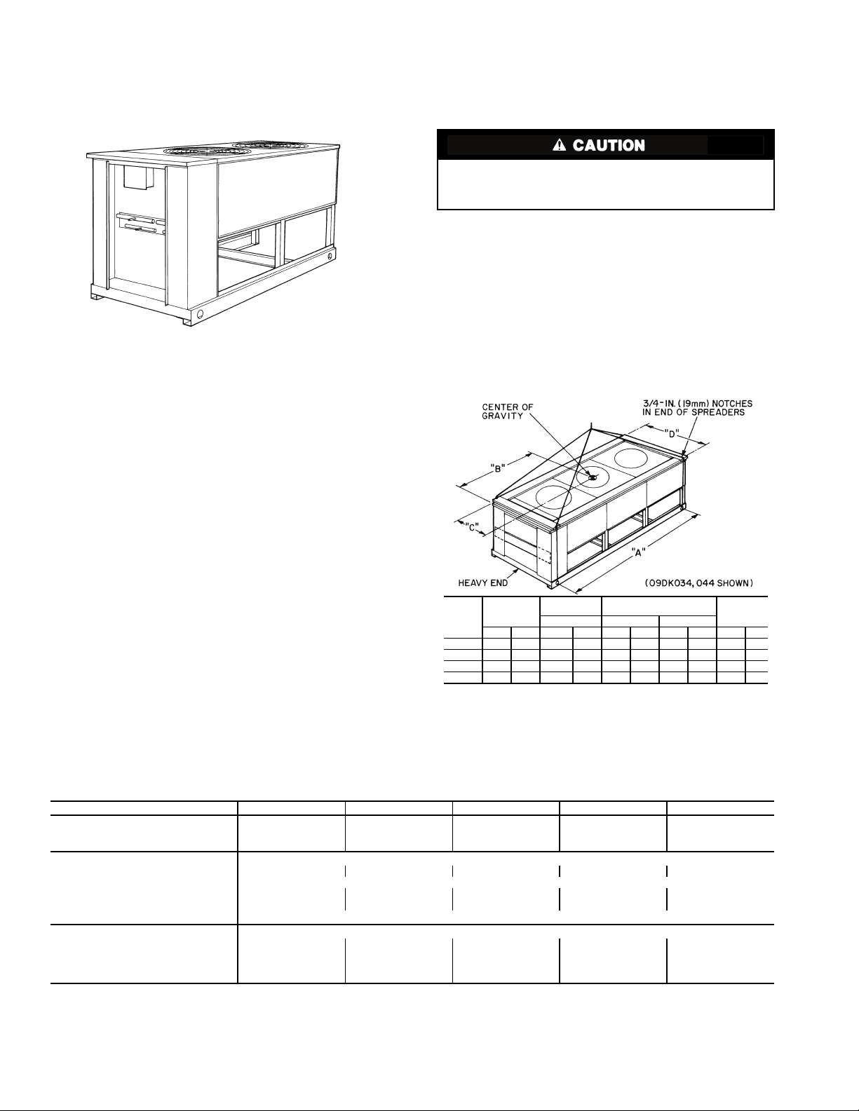
Fig. 1 — Model 09DK (Size 028 Shown)
Fig. 2 — Rigging with Spreader Bars
(Field Supplied)
UNIT
09DK
MAX. SHIP
WT
LIFTING
HOLES
CENTER OF
GRAVITY
D
ABC
lb kg in. mm in. mm in. mm in. mm
020,024 989 449 95.7 2432 55.2 1403 24.7 628 49.5 1256
028 1209 548 95.7 2432 54.7 1391 36.7 933 73.5 1867
034 1835 832 142.0 3608 80.0 2032 36.7 933 73.5 1867
044 2017 915 142.0 3608 80.0 2032 36.7 933 73.5 1867
These instructions describe installation, start-up, and service of 09DK020-044 air-cooled condensers (Fig. 1). See
Table 1 for general unit physical data.
INSTALLATION
Step 1 — Complete Pre-Installation Checks —
Examine for damage incurred during shipment. File claim
immediately with transit company if damage is found. Verify
that the nameplate electrical requirements match the available
power supply. Check the shipment for completeness.
Step 2 — Locate and Rig Unit, Remove Shipping Skid
LOCATION — If roof installation is specified, make certain
that roof structure can support the condenser weight. Refer to
Table 1.
Locate condenser where an adequate supply of inlet outdoor
air is available. Do not locate where the possibility of air recirculation exists, such as under a roof overhang.
Locate condenser in an area free from airborne dirt or other
foreign material which could clog condenser coils.
RIGGING — Preferred method is with spreader bars from
above the unit. Use 2-in. (50 mm) OD pipe or hooks in lifting
holes. Rig with 4 cables and spreader bars. All panels must be
in place when rigging. See rigging label on unit for details concerning shipping weights, distance between lifting holes, center of gravity, and spreader bar dimensions. Also see Fig. 2.
If overhead rigging is not possible, place unit on skid or pad
for rolling or dragging. When rolling, use minimum of 3 rollers. When dragging, pull the pad. Do not apply force to the
unit. When in final position, raise from above to lift unit off
pad.
All panels must be in place when rigging. Do not forklift
unit if no skid is supplied. If unit has skid, use forklift truck
from sides only.
PLACING UNIT — There must be 4 ft (1.22 m) for service
and for unrestricted airflow on all sides of unit, and a minimum
of 8 ft (2.44 m) clean air space above units. See Fig. 3, 4, and
5. For multiple units, allow 8 ft (2.44 m) separation between
units for airflow and service.
MOUNTING UNIT — When unit is in proper location, use
mounting holes in base rails for securing unit to supporting
structure. Fasteners for mounting unit must be field supplied. If
unit is to be mounted on vibration isolators, drill mounting
holes in bottom of base rail at support points 1-4 (shown in
Fig. 3, 4, and 5) and locate isolators at those points.
Table 1 — Physical Data — 50 and 60 Hz
UNIT 09DK 020 024 028 034 044
OPERATING WEIGHT, lb (kg)
Aluminum-Fin Units 797 (361.5) 797 (361.5) 983 (445.9) 1495 (678.1) 1676 (760.2)
Copper-Fin Units 921 (417.8) 921 (417.8) 1137 (515.7) 1700 (771.1) 1984 (900.0)
CONDENSER FANS, TYPE Propeller Type, Direct Driven
No. 22233
Diam, in. (mm) 30 (762)
Total Airflow cfm 10,600 13,500 15,700 21,100 23,700
Speed, Rpm (rps) 1140 (19), 60 Hz 950 (15.8), 50 Hz
CONDENSER COIL, TYPE Horizontal, Plate Fin
Rows 33223
Fins/in. (Fins/m) 17 (669) 17 (669) 19 (748) 17 (669) 17 (669)
Total Face Area, sq ft 23.5 23.5 39.2 58.4 58.4
L/s 5,000 6,370 7,400 9,950 11,200
sq m 2.18 2.18 3.64 5.43 5.43
2
Page 3

Fig. 3 — Dimensions, 09DK020-028
DIMENSIONS — MM [FT-IN.]
NOTES:
1. There must be 1220 mm [4-0] for service and for unrestricted airflow on
all sides of unit.
2. There must be minimum 2440 mm [8-0] clear air space above unit.
3. The approximate operating weight of the unit follows:
4. Dimensions are in millimeters. Dimensions in [ ] are in feet-inches.
UNIT
09DK
ABCDEF
020,024
1131
[3-8
1
/2]
1007
[3-311/16]
240
[97/16]
432
[1-0]
228
[0-9]
559
[1-10]
028
1742
[5-8
5
/8]
1619
[5-33/4]
496
[1-79/16]
914
[3-0]
445
[1-51/2]
762
[2-6]
UNIT 09DK
TOTAL
WEIGHT
OPERATING WT. AT SUPPORT
POINTS
Lb Kg Lb Kg Lb Kg
020,024 797 361.5 186 84.4 212 96.2
020C,024C 921 417.8 215 97.5 245 111.1
028 983 445.9 229 103.9 262 118.8
028C 1137 515.7 268 121.6 300 136.1
C—Units with optional copper-fin coils
1&2
3&4
3
Page 4

Fig. 4 — Dimensions, 09DK034
DIMENSIONS — MM [FT-IN.]
NOTES:
1. There must be 1220 mm [4-0] for service and for unrestricted airflow on
all sides of unit.
2. There must be minimum 2440 mm [8-0] clear air space above unit.
3. The approximate operating weight of the unit follows:
4. Dimensions are in millimeters. Dimensions in [ ] are in feet-inches.
UNIT
09DK
BCDE F
034
112
[1-2
7
/16]
496
[1-79/16]
914
[3-0]
445
[1-51/2]
762
[2-6]
UNIT 09DK
TOTAL
WEIGHT
OPERATING WT. AT SUPPORT
POINTS
Lb Kg Lb Kg Lb Kg
034 1495 678.1 349 158.3 399 181.0
034C 1700 771.1 396 179.6 454 205.9
C—Units with optional copper-fin coils
1&2
3&4
4
Page 5

Fig. 5 — Dimensions, 09DK044
COIL CONNECTION DIMENSIONS — MM [IN.]
NOTES:
1. There must be 1220 mm [4-0] for service and for unrestricted airflow on
all sides of unit.
2. There must be minimum 2440 mm [8-0] clear air space above unit.
3. The approximate operating weight of the unit follows:
4. Dimensions are in mm. Dimensions in [ ] are in feet-inches.
5. Dimension “E” for 34.9 mm I.D. is 118 mm [4
5
/8].
Dimension “E” for 28.5 mm I.D. is 112 mm [4
7
/16].
UNIT
09DK
ABCD E
044
34.9 I.D.
[1
3
/8]
28.5 I.D.
[11/8]
22.2 I.D.
[7/8]
15.9 I.D.
[5/8]
SEE
NOTE #5
UNIT 09DK
TOTAL
WEIGHT
OPERATING WT. AT SUPPORT
POINTS
Lb Kg Lb Kg Lb Kg
044 1676 760.2 391 177.4 447 202.8
044C 1984 900.0 462 209.6 529 240.0
C—Units with optional copper-fin coils
1&2
3&4
5
Page 6

Step 3 — Complete Refrigerant Piping
GENERAL — All field leak and pressure testing should be in
accordance with local code requirements. If no local code
exists, follow American National Standards Institute (ANSI)/
American Society of Heating, Refrigeration and Air Conditioning Engineers (ASHRAE) Safety Standard 15, latest
revision.
For leak testing procedures, refer to the Carrier Refrigerant
Service Techniques Manual.
COIL CIRCUITING CONVERSION INSTRUCTIONS —
See Table 2 for standard unit circuiting and for the circuiting
available by installing the supplied parts kits. Note that for
044 size units, all circuiting must be field installed using field
supplied parts. Field supplied and installed parts are also
required for 100% circuiting of all 020-034 size units.
The following sections describe how to modify the standard
unit circuiting (as shipped from the factory) for optional splits.
NOTE: All coils are purged with dry air and then capped prior
to shipment. The coils DO NOT contain a refrigerant holding
charge.
Table 2 — Coil Circuiting Options
UNIT 09DK
020 50/50% 67/33%*
024 50/50% 67/33%*
028 50/50% 60/40%* or 40/40/20%*
034 50/50% 60/40%* or 40/40/20%*
044 Uncircuited†
*Parts kits for field circuiting conversions are supplied with the unit. Replacement parts kits are available as follows:
For 020 and 024 size units, part no. 09DK400138; for 028 and 034 units, part no. 09DK400139. Replacement parts kits are not
available for 044 units.
†The 044 unit is shipped from the factory uncircuited, with plastic caps on all connections. The unit must be field converted to the
desired split with field supplied parts.
FAC TOR Y
CIRCUITING
FIELD-CONVERTED
CIRCUITING
100% or 74/26% or 66/34% or
60/40% or 53/47% or 40/13/13/34%
6
Page 7

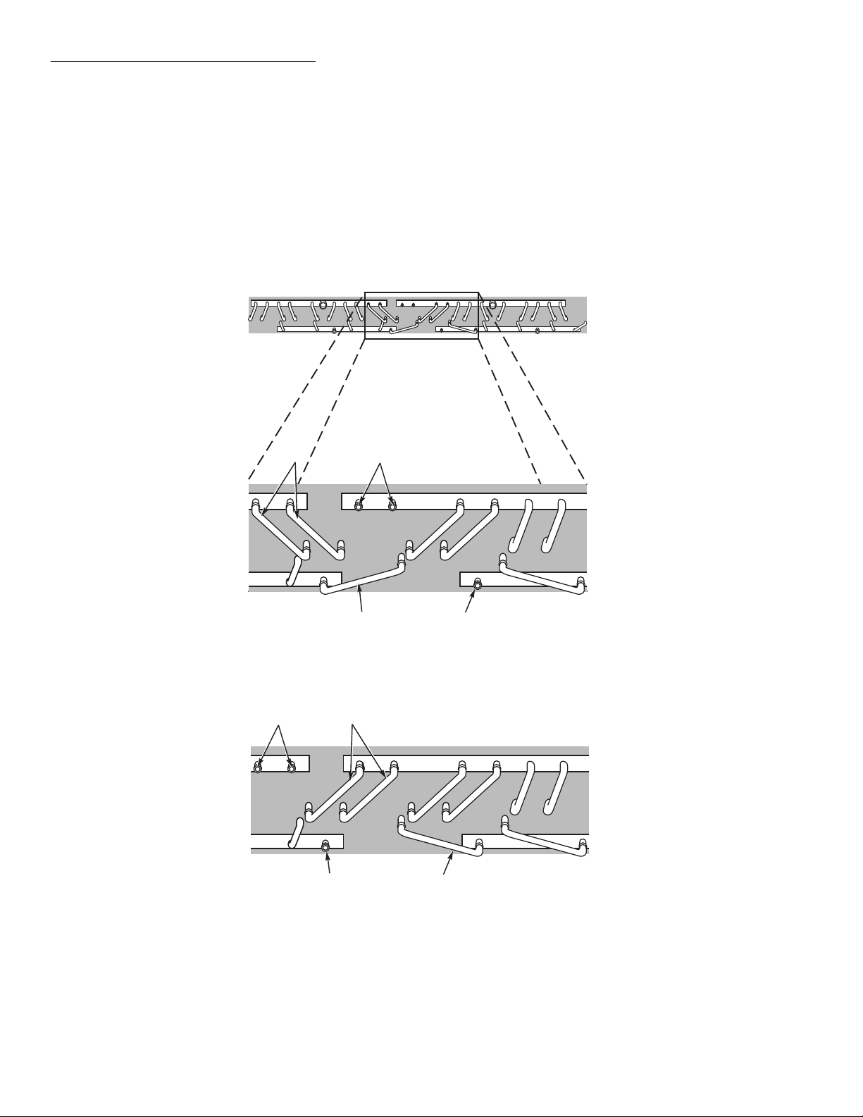
09DK020,024 67/33% Circuiting Modification
CA
AB
Fig. 6 — Parts Removed from 09DK020,024
(50/50%) Unit for 67/33% Circuiting
Fig. 7 — Parts Added to 09DK020,024 Unit
(To Obtain 67/33% Circuiting)
— To convert the 09DK020 or 09DK024 coil from the 50/50% to
67/33% circuiting, perform the following steps:
1. Use a mini tubing cutter to remove specified parts:
a. Both
3
/8-in. diam tube nipples connecting the left
hot gas header to the coil. See Fig. 6, Item A.
b. The
3
/8-in. diam tube nipple connecting the left
liquid header to the coil. See Fig. 6, Item B.
c. Caps, where 2 are located on the right gas header,
and one is located on the right liquid header. See
Fig. 6, Item C.
2. Attach following specified parts contained in the parts
kit. Perform phos-copper brazing on all field-made
connections while protecting adjacent joints from heat.
a. Cap the open stub tubes on the left headers, where
two are located on the gas header, and one on the
liquid header. See Fig. 7, Item A.
b. Insert both 3
5
/8-in. length tube nipples into the
open stub tubes located on the right side of the coil
to connect the right gas header to the top row of
the coil. See Fig. 7, Item B.
c. Insert the 4
11
/16-in. length tube nipple into the
open stub tubes on the right side of the coil to connect the right liquid header to the bottom row. See
Fig. 7, Item C.
3. Install or replace filter-drier(s). Before charging the
system, install or replace filter drier(s) connected to
the liquid line near the indoor unit to prevent contamination in the system.
7
Page 8
09DK028,034 60/40% Circuiting Modification
B
C
A
C
B
A
C
A
Fig. 8 — Parts Removed from 09DK028,034 (50/50%) Unit for 60/40% Circuiting
Fig. 9 — Parts Added to 09DK028,034 Unit
(To Obtain 60/40% Circuiting)
— To convert the 09DK028 or 09DK034 coil from the 50/50% to
60/40% circuiting, perform the following steps:
1. Use a mini tubing cutter to remove specified parts:
a. Both
3
/8-in. diam tube nipples connecting the left
hot gas header to the coil. See Fig. 8, Item A.
b. The
3
/8-in. diam tube nipple connecting the left
liquid header to the coil. See Fig. 8, Item B.
c. Caps, where 2 are located on the right gas header,
and one is located on the right liquid header. See
Fig. 8, Item C.
2. Attach following specified parts contained in the parts
kit. Perform phos-copper brazing on all field-made
connections while protecting adjacent joints from heat.
a. Cap the open stub tubes on the left headers, where
two are located on the gas header, and one on the
liquid header. See Fig. 9, Item A.
b. Insert both 4
1
/16-in. length tube nipples into the
open stub tubes on the right side of the coil, connecting the gas header to the top row. See Fig. 9,
Item B.
c. Insert the 4
11
/16-in. length tube nipple into the
open stub tubes on the right side of the coil, connecting the liquid header to the bottom row. See
Fig. 9, Item C.
3. Install or replace filter-drier(s). Before charging the
system, install or replace filter drier(s) connected to
the liquid line near the indoor unit to prevent contamination in the system.
8
Page 9

09DK028,034 40/40/20% Circuiting Modification
BB
A
A
A A
ABAC
Fig. 10 — Parts Removed from 09DK028,034 (50/50%) Unit for 40/40/20% Circuiting
Fig. 11 — Parts Added to 09DK028,034 Unit
(To Obtain 40/40/20% Circuiting)
— To
convert the 09DK028 or 09DK034 coil from the 50/50% to
40/40/20% circuiting, perform the following steps:
1. Use a mini tubing cutter to remove specified parts:
a. Four
3
/8-in. diam tube nipples connecting the hot
gas headers to the coil. See Fig. 10, Item A.
b. Both
3
/8-in. diam tube nipples connecting the liq-
uid headers to the coil. See Fig. 10, Item B.
2. Attach following specified parts contained in the parts
kit. Perform phos-copper brazing on all field-made
connections while protecting adjacent joints from heat.
a. Cap the open stub tubes on the left and right gas
and liquid headers with stub tube caps supplied in
the parts kit. See Fig. 11, Item A.
b. Insert the
7
/8-in. diam header into the stub tubes
located in the top row of the coil. See Fig. 11,
Item B.
c. Insert the 6-in. length U tube into the stub tubes
located in the bottom row of the coil. See Fig. 11,
Item C.
3. Install or replace filter-drier(s). Before charging the
system, install or replace filter drier(s) connected to
the liquid line near the indoor unit to prevent contamination in the system.
9
Page 10

09DK044 100% Circuiting Modification
A
B
B
A
C
D
C
PLASTIC CAPS REMOVED FROM UNIT
FIELD-SUPPLIED PARTS ADDED TO UNIT
Fig. 12 — 09DK044 Unit with 100% Circuiting
— To configure the
09DK044 for a single 100% refrigerant circuit using field supplied parts, perform the following steps:
1. Remove all plastic caps. Refer to Fig. 12.
2. Attach following parts as shown in Fig. 12. Perform
phos-copper brazing on all field-made connections
while protecting adjacent joints from heat.
a. Construct one (1) gas tubing assembly (Item A),
consisting of the following parts, and braze it into
gas headers as shown:
3
2 —1
/8-in. OD tubes
3
2 —1
/8-in. 90° long-radius elbows
3
1 —1
/8-in. tee (see note at right)
3
2 —1
/8-in. OD nipples (cut to length as required)
b. Construct 2 gas “U” tube assemblies (Item B),
consisting of the following parts, and braze them
into the gas headers as shown.
1
1 —1
/8-in. OD tube
1
2 —1
/8-in. 90° long-radius elbows
1
2 —1
/8-in. OD nipples (cut to length as required)
c. Construct one liquid tubing assembly (Item C),
consisting of the following parts, and braze it into
liquid headers as shown.
7
2 —
/8-in. OD tubes
7
1 —
/8-in. 90° long-radius elbow
7
1 —
/8-in. tee (see note below)
7
2 —
/8-in. OD nipples (cut to length as required)
d. Construct 2 liquid “U” tube assemblies (Item D),
consisting of the following parts, and braze them
into the gas headers as shown.
5
1 —
/8-in. OD tube
5
2 —
/8-in. 90° long-radius elbows
5
2 —
/8-in. OD nipples (cut to length as required)
NOTE: Diameter of tee’s interconnecting pipe
opening is dependent upon interconnecting system
piping diameter. Refer to Carrier System Design
Manual, Part 3, for hot gas and liquid pipe sizing
information.
3. Install or replace filter drier(s). Before charging the
system, install or replace filter drier(s) connected to
the liquid line near the indoor unit to prevent contamination in the system.
10
Page 11

09DK044 74/26% Circuiting Modification
AE
B
E
C
ED
E
PLASTIC CAPS REMOVED FROM UNIT
FIELD-SUPPLIED PARTS ADDED TO UNIT
Fig. 13 — 09DK044 Unit with 74/26% Circuiting
— To configure
the 09DK044 for two refrigerant circuits (one with 74%
capacity and one with 26% capacity) using field supplied
parts, perform the following steps:
1. Remove all plastic caps. Refer to Fig. 13.
2. Attach following parts as shown in Fig. 13. Perform
phos-copper brazing on all field-made connections
while protecting adjacent joints from heat.
a. Construct the 74% gas tubing assembly (Item A),
consisting of the following parts, and braze it into
gas headers as shown in Fig. 13, Item A:
3
2 —1
/8-in. OD tubes (cut to length as required)
3
2 —1
/8-in. 90° long-radius elbows
3
1 —1
/8-in. tee (see note at right)
3
2 —1
/8-in. OD nipples (cut to length as required)
b. Construct the 26% gas tubing assembly (Item B),
consisting of the following parts, and braze it into
the gas headers as shown in Fig. 13, Item B:
1
1 — 1
/8-in. OD tube (cut to length as required)
1
2 — 1
/8-in. 90° long-radius elbows
1
1 — 1
/8-in. tee (see note at right)
1
2 — 1
/8-in. OD nipples (cut to length as required)
c. Construct the 74% liquid tubing assembly
(Item C), consisting of the following parts, and
braze it into liquid headers as shown in Fig. 13,
Item C:
7
2 —
/8-in. OD tubes (cut to length as required)
7
2 —
/8-in. 90° long-radius elbows
7
1 —
/8-in. tee (see note at right)
7
2 —
/8-in. OD nipples (cut to length as required)
d. Construct the 26% liquid tube assembly (Item D),
consisting of the following parts, and braze it into
the gas headers as shown in Fig. 13, Item D:
5
1 —
/8-in. OD tube
5
2 —
/8-in. 90° long-radius elbows
5
1 —
/8-in. tee (see note below)
5
2 —
/8-in. OD nipples (cut to length as required)
e. Plug the two open 1
the gas headers and the two open
1
/8-in. diameter stub tubes on
5
/8-in. diameter
stub tubes on the liquid headers as shown in
Fig. 13, Item E. Parts required:
1
2 —1
/8-in. plug fittings
5
2 —
/8-in. plug fittings
NOTE: Diameter of tee’s interconnecting pipe
opening is dependent upon interconnecting system
piping diameter. Refer to Carrier System Design
Manual, Part 3, for hot gas and liquid pipe sizing
information.
3. Install or replace filter drier(s). Before charging the
system, install or replace filter drier(s) connected to
the liquid line near the indoor unit to prevent contamination in the system.
11
Page 12

09DK044 66/34% Circuiting Modification
A
C
B
C
PLASTIC CAPS REMOVED FROM UNIT
FIELD-SUPPLIED PARTS ADDED TO UNIT
Fig. 14 — 09DK044 Unit with 66/34% Circuiting
— To configure
the 09DK044 for two refrigerant circuits (one with 66% capacity and one with 34% capacity) using field supplied parts,
perform the following steps:
1. Remove all plastic caps. Refer to Fig. 14.
2. Attach following parts as shown in Fig. 14. Perform
phos-copper brazing on all field-made connections
while protecting adjacent joints from heat.
a. Construct the 66% gas tubing assembly (Item A),
consisting of the following parts, and braze it into
gas headers as shown in Fig. 14, Item A:
1
2 — 1
/8-in. OD tubes (cut to length as required)
1
2 — 1
/8-in. 90° long-radius elbows
1
1 — 1
/8-in. tee (see note at right)
1
3 — 1
/8-in. OD nipples (cut to length as required)
b. Construct the 66% liquid tubing assembly
(Item B), consisting of the following parts, and
braze it into liquid headers as shown in Fig. 14,
Item B:
5
2 —
/8-in. OD tubes (cut to length as required)
5
2 —
/8-in. 90° long-radius elbows
5
1 —
/8-in. tee (see note at right)
5
3 —
/8-in. OD nipples (cut to length as required)
c. Plug the open 1
right gas header and the open
1
/8-in. diameter stub tube on the
5
/8-in. diameter stub
tube on the right liquid header as shown in Fig. 14,
Item C. Parts required:
1
1 — 1
/8-in. plug fitting
5
1 —
/8-in. plug fitting
NOTE: Diameter of tee’s interconnecting pipe
opening is dependent upon interconnecting system
piping diameter. Refer to Carrier system Design
Manual, Part 3 for hot gas and liquid pipe sizing
information.
3. Install or replace filter drier(s). Before charging the
system, install or replace filter drier(s) connected to
the liquid line near the indoor unit to prevent contamination in the system.
12
Page 13

09DK044 60/40% Circuiting Modification
C
A
C
B
PLASTIC CAPS REMOVED FROM UNIT
FIELD-SUPPLIED PARTS ADDED TO UNIT
Fig. 15 — 09DK044 Unit with 60/40% Circuiting
— To configure
the 09DK044 for two refrigerant circuits (one with 60%
capacity and one with 40% capacity) using field supplied
parts, perform the following steps:
1. Remove all plastic caps. Refer to Fig. 15.
2. Attach following parts as shown in Fig. 15. Perform
phos-copper brazing on all field-made connections
while protecting adjacent joints from heat.
a. Construct the 60% gas tubing assembly (Item A),
consisting of the following parts, and braze it into
gas headers as shown in Fig. 15, Item A:
1
2 — 1
/8-in. OD tubes (cut to length as required)
1
2 — 1
/8-in. 90° long-radius elbows
1
1 — 1
/8-in. tee (see note at right)
1
3 — 1
/8-in. OD nipples (cut to length as required)
b. Construct the 60% liquid-tubing assembly
(Item B) consisting of the following parts and
braze it into liquid headers as shown in Fig. 15,
Item B:
5
2 —
/8-in. OD tubes (cut to length as required)
5
2 —
/8-in. 90 long-radius elbows
5
1 —
/8-in. tee (see note at right)
5
3 —
/8-in. OD nipples (cut to length as required)
c. Plug the open 1
left gas header and the open
1
/8-in. diameter stub tube on the
5
/8-in. diameter stub
tube on the left liquid header as shown in Fig. 15,
Item C. Parts required:
1
1 — 1
/8 in. plug fitting
5
1 —
/8-in. plug fitting
NOTE: Diameter of tee’s interconnecting pipe
opening is dependent upon interconnecting system
piping diameter. Refer to Carrier System Design
Manual, Part 3 for hot gas and liquid pipe sizing
information.
3. Install or replace filter drier(s). Before charging the
system, install or replace filter drier(s) connected to
the liquid line near the indoor unit to prevent contamination in the system.
13
Page 14

09DK044 53/47% Circuiting Modification
A
C
B
D
PLASTIC CAPS REMOVED FROM UNIT
FIELD-SUPPLIED PARTS ADDED TO UNIT
Fig. 16 — 09DK044 Unit with 53/47% Circuiting
— To configure the 09DK044 for two refrigerant circuits (one with 53%
capacity and one with 47% capacity) using field supplied
parts, perform the following steps:
1. Remove all plastic caps. Refer to Fig. 16.
2. Attach following parts as shown in Fig. 16. Perform
phos-copper brazing on all field-made connections
while protecting adjacent joints from heat.
a. Construct the 53% gas tubing assembly (Item A),
consisting of the following parts, and braze it into
gas headers as shown in Fig. 16, Item A:
1
2 — 1
/8-in. OD tubes (cut to length as required)
1
2 — 1
/8-in. 90° long-radius elbows
1
2 — 1
/8-in. OD nipples (cut to length as required)
b. Construct the 53% liquid tubing assembly
(Item B), consisting of the following parts, and
braze it into liquid headers as shown in Fig. 16,
Item B:
5
2 —
/8-in. OD tubes (cut to length as required)
5
2 —
/8-in. 90° long-radius elbows
5
2 —
/8-in. OD nipples (cut to length as required)
c. Construct the 47% gas tubing assembly (Item C),
consisting of the following parts, and braze it into
gas headers as shown in Fig. 16, Item C:
1
2 — 1
/8-in. OD tubes (cut to length as required)
1
2 — 1
/8-in. 90° long-radius elbows
1
2 — 1
/8-in. OD nipples (cut to length as required)
d. Construct the 47% liquid tubing assembly
(Item D), consisting of the following parts, and
braze it into liquid headers as shown in Fig. 16,
Item D:
5
2 —
/8-in. OD tubes (cut to length as required)
5
2 —
/8-in. 90 long-radius elbows
5
2 —
/8-in. OD nipples (cut to length as required)
3. Install or replace filter drier(s). Before charging the
system, install or replace filter drier(s) connected to
the liquid line near the indoor unit to prevent contamination in the system.
14
Page 15

09DK044 40/13/13/34% Circuiting Modification
A
B
PLASTIC CAPS REMOVED FROM UNIT
FIELD-SUPPLIED PARTS ADDED TO UNIT
Fig. 17 — 09DK044 Unit with 40/13/13/34% Circuiting
— To configure the 09DK044 for four refrigerant circuits (one with
40% capacity, two with 13% capacity, and one with 30%
capacity) using field supplied parts, perform the following
steps:
1. Remove all plastic caps. Refer to Fig. 17.
2. Attach following parts as shown in Fig. 17. Perform
phos-copper brazing on all field-made connections
while protecting adjacent joints from heat.
a. Plug the open 1
1
/8-in. stub tubes at the inside of
each of the large gas headers as shown in Fig. 17,
Item A. Parts required:
1
2 — 1
/8-in. plug fittings
5
b. Plug the open
/8-in. stub tubes at the inside of
each of the large gas headers as shown in Fig. 17,
Item B. Parts required:
5
2 —
/8-in. plug fittings
3. Install or replace filter drier(s). Before charging the
system, install or replace filter drier(s) connected to
the liquid line near the indoor unit to prevent contamination in the system.
15
Page 16

REFRIGERANT LINE SIZING — Sizing depends on length
*Field supplied.
NOTES:
1. Hot gas lines should rise above refrigerant level in condenser
circuit.
2. Trap should be installed on hot gas lines to prevent condenser
oil and refrigerant vapor migration from accumulating on compressor heads during off cycle.
3. Refer to Carrier System Design Manual, part 3 for proper piping sizes and design.
4. For piping lengths greater than 50 ft (15.2 m), provide support
to liquid and gas lines near the connections to the coil.
Fig. 18 — Typical Piping for 09DK Condenser with a Single Compressor
of lines between various sections of the refrigerant system.
Consider the amount of liquid lift and drop in the system as
well as proper compressor oil return. Consult Carrier System
Design Manual, Part 3, for proper piping sizes and design.
LIQUID SHUTOFF VALVE AND SIGHT GLASS — A
shut-off valve is not supplied with 09DK condensers. It is
strongly recommended that a full line size liquid shutoff valve
(see Fig. 18 and 19) be field supplied near condenser to allow
for servicing parts of the refrigerant circuit. A field-supplied
moisture indicating sight glass is recommended for use in
charging and servicing the system. Refer to Fig. 20.
PRESSURE RELIEF — The American National Standards
Institute and American Society of Heating, Refrigeration, and
Air Conditioning Engineers Safety Code for Mechanical
Refrigeration (ANSI/ASHRAE) 15 states the following:
“Every refrigerant system shall be protected by a pressure
relief device unless so constructed that the pressure due to fire
conditions will be safely relieved by some part of the system.”
Since 09DK condensers have no pressure relief device, one
should be field supplied and installed just before the liquid line
service valve. (See Fig. 18 and 19.) When the split coil is used
with multiple systems, each system must have its own pressure
relief.
REFRIGERANT RECEIVER — A refrigerant receiver is not
furnished with 09DK condensers and is not recommended for
normal applications as its use will be detrimental to the desired
effects of subcooling. However, if a particular application
requires a receiver to increase refrigerant holding capacity of
the condenser, a receiver can be used. When a receiver is to be
used all year, it should be installed indoors. Carrier recommends the following installation in such a case (see Fig. 20).
Locate valves on each side of the receiver so receiver may be
isolated from system for normal operation.
16
Page 17

Procedure for Using the Refrigerant Receiver
*Field supplied.
NOTES:
1. Hot gas lines should rise above refrigerant level in condenser
circuit.
2. Trap should be installed on hot gas lines to prevent condenser
oil and refrigerant vapor migration from accumulating on compressor heads during off cycle.
3. Refer to Carrier System Design Manual, part 3 for proper piping
sizes and design.
4. For piping lengths greater than 50 ft (15.2 m), provide support
to liquid and gas lines near the connections to the coil.
Fig. 19 — Typical Piping for 09DK Condenser with a Dual Split System
*Field-supplied service valves.
A—Bypass valve
B—Receiver inlet valve
C—Receiver outlet
valve
Fig. 20 — Piping for Optional Receiver
During normal operation — Valve A is open and valves B and
C are closed. Receiver is isolated from the system.
For servicing — Valves A and C are closed and valve B is
open. Run unit until all the refrigerant is in the receiver and
then close valve B. Unit is now ready for servicing.
To resume operation — Leave valve A closed and open valves
B and C. Run unit until the stored refrigerant is drawn into the
system. To completely remove the refrigerant from the
receiver, throttle valve B while noting condition of refrigerant
in the liquid line sight glass; also monitor the suction pressure.
A sudden surge of bubbles in the sight glass and a rapid
decrease in suction pressure indicates that all the refrigerant
has been withdrawn from the receiver. Immediately close
valves B and C and then open valve A. The unit should now be
ready for normal operation, with the receiver isolated from the
system. The system should be charged to a clear sight glass
when under normal operation.
COIL CONNECTIONS — See Fig. 3-5, 18, and 19 for the
necessary connections.
— See Fig. 20.
17
Page 18

Step 4 — Complete Electrical Connections
GENERAL — Verify that nameplate electrical requirements
match available power supply. Voltage at condenser must be
within the minimum and maximum shown in Table 3 and
phases must be balanced within 2%. Contact local power company for line voltage corrections. Never operate a motor where
a phase imbalance in supply voltage is greater than 2%. Use
the following formula to determine the percentage of voltage
imbalance:
% Voltage
Imbalance
= 100 x
Example: Supply voltage is 240-3-60.
Determine maximum deviation from average voltage:
(AB) 243 – 239 = 4 volts
(BC) 239 – 236 = 3 volts
(AC) 239 – 238 = 1 volt
Maximum deviation is then 4 volts. To determine the percentage of voltage imbalance:
% Voltage Imbalance = 100 x
This amount of phase imbalance is satisfactory since it is
below the maximum allowable of 2%.
IMPORTANT: If supply voltage phase imbalance is
more than 2%, contact your local electric utility
company immediately.
Condenser operation on improper line voltage or excessive
phase imbalance may be considered abuse and any resulting
damage may not be covered by Carrier warranty.
All wiring must be in accordance with NEC (National Electrical Code, U.S.A.) regulations or local codes.
CONNECTIONS — Refer to Table 3 and Fig. 21.
Install a field-supplied disconnect capable of being locked
at OFF position.
POWER WIRING — Install field-supplied branch circuit
fused disconnect(s) of a type that can be locked OFF or OPEN.
Disconnect(s) must be within sight from and readily accessible
from unit in compliance with NEC Article 440-14 (U.S.A.) or
local code.
max voltage deviation
from average voltage
Average voltage
AB = 243 volts
BC = 236 volts
AC = 238 volts
Average Voltage =
=1.7%
243 + 236 + 238
717
=
3
= 239 volts
4
239
3
GENERAL WIRING NOTES
1. The control circuit field supply disconnect should
never be open except when unit is being serviced or is
to be down for a prolonged period.
2. Power entry is at one end only.
3. Terminals for field power supply are suitable for copper, copper-clad aluminum, or aluminum conductors.
Insulation must be rated 60 C minimum.
4. Field power supply wires based on minimum 26 C
ambient temperature air are 8 AWG (American Wire
Gage) for Models 09DK034, 044 (208/230-3-60,
230-3-50), 12 AWG for all other models.
5. Connect field power wires to factory-supplied 8 AWG
wire from contactor with factory-supplied nut.
6. Route field wiring through factory-supplied wire ties
and base rail holes. See Fig. 3-5.
7. Control circuit power is as follows:
CONTROL CIRCUIT
V-H z
220-60 380-60
230-50
115-60
NOTE: Use 14 AWG (American Wire Gage) copper conductors only
for control circuit wiring.
POWER
SUPPLY V-Hz
230-50
400-50
208/230-60
460-60
575-60
Step 5 — Add Accessories as Needed —
Accessories include fan cycling head-pressure control, winter
start control, fan cycling, and electrical interlock. Refer to
installation instructions furnished with each accessory.
START-UP
System Evacuation and Dehydration —
GTAC II, Module 4, “Dehydration for Proper Evacuation and
Dehydration techniques.”
Refer to
Charging Procedure — BEFORE CHARGING THE
SYSTEM, INSTALL OR REPLACE THE FILTERDRIER(S) CONNECTED TO THE LIQUID LINE WITHIN
THE IN-DOOR UNIT(S) TO PREVENT CONTAMINATION WITHIN THE SYSTEM. Charge to a clear sight glass.
Refer to GTAC II, Module 5 “Charging, Recovery, Recycling,
and Reclamation” and Carrier Refrigerant Service Techniques
manual for proper charging techniques. Add 10 lbs (4.5 kg) of
R-22 over clear sight glass to flood subcooler sections of the
condenser coils. See Table 4 for charging data.
Check Operation of Condenser Fan Motor
Controls and Rotation of Fans — Rotation should
be counterclockwise as viewed from top of unit.
Before starting unit, be sure wire fan guards are secured in
place over each fan.
18
Page 19

020
Fig. 21 — Wiring Diagram, Power Schematic; 09DK020-044
FC — Fan Contactor
FM — Fan Motor
TB — Terminal Block Connection
Terminal Block Connection
Marked Terminal
Unmarked Terminal
Splice
Factory Wire
Field Control Wiring
Field Power Wiring
LEGEND
024
028
034
044
024
028
034
044
Table 3 — 09DK Electrical Data
60 HERTZ
UNIT
09DK
500 208/230 187 254 14.8 20
200 380 342 418 8.8 15 3.9 220
600 460 414 508 7.4 15 3.3 115
100 575 518 632 7.6 15 3.4 115
500 208/230 187 254 14.8 20 6.6 115
200 380 342 418 8.8 15 3.9 220
600 460 414 508 7.0 15 3.3 115
100 575 518 632 7.6 15 3.4 115
500 208/230 187 254 13.9 20 6.6 115
200 380 342 418 8.8 15 3.9 220
600 460 414 508 7.4 15 3.3 115
100 575 518 632 7.6 15 3.4 115
500 208/230 187 254 21.4 25
200 380 342 418 12.7 20 3.9 220
600 460 414 508 10.7 15 3.3 115
100 575 518 632 11.0 15 3.4 115
500 208/230 187 254 20.1 25 6.6 115
200 380 342 418 12.7 20 3.9 220
600 460 414 508 10.1 15 3.3 115
100 575 518 632 11.0 15 3.4 115
UNIT
09DK
800 230 207 254 14.4 20
900 400 342 440 6.7 15 3.0 230
800 230 207 254 14.4 20 6.4 230
900 400 342 440 6.7 15 3.0 230
800 230 207 254 20.8 30
900 400 342 440 9.7 15 3.0 230
800 230 207 254 20.8 30 6.4 230
900 400 342 440 9.7 15 3.0 230
Volts -3 Ph
Volts -3 Ph
Supplied Volts
Min Max
Supplied Volts
Min Max
UNIT FAN MOTORS CONTROL CIRCUIT
MCA
MOCP
(Fuse)
No. FLA (ea) Volts -1 Ph Amps
6.6 115
2
6.2 115
3
50 HERTZ
UNIT FAN MOTORS CONTROL CIRCUIT
MCA
MOCP
(Fuse)
No. FLA (ea) Volts -1 Ph Amps
6.4 230
2
6.4 230
3
7
7
FLA — Full Load Amps
MCA — Minimum Circuit Amps (for wire sizing). Complies with
MOCP — Maximum Overcurrent Protective Device (Amps).
NEC (National Electrical Code, U.S.A.) Section 430-24.
19
Page 20
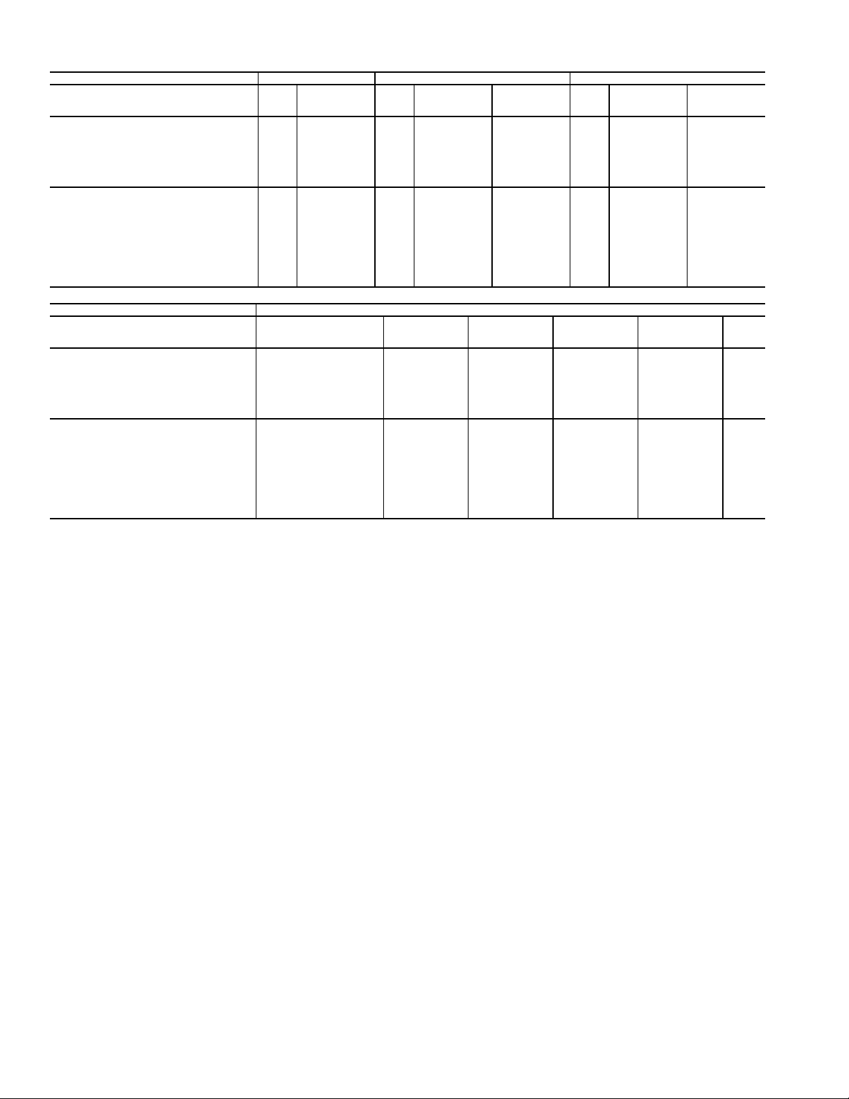
Table 4 — Refrigerant Circuit Data
COIL
No. of Ckts 2112112121121
Cap. (% Ckt) 50 67 33 50 60 40 40 20 50 60 40 40 20
REFRIGERANT
Min. Operating Chg/Ckt* kg 4.8 6.4 3.2 5.3 6.4 4.3 4.3 2.1 8.0 9.5 6.4 6.4 3.2
Optimum Operating Chg/Ckt† kg 5.7 7.5 3.8 6.3 7.5 5.0 5.0 2.5 9.4 11.2 7.5 7.5 3.7
Vol /C kt m
STORAGE CAPACITY
(Per Ckt)**
R-12 kg 8.7 11.7 5.8 9.6 11.5 7.7 7.7 3.8 14.2 17.1 11.3 11.3 5.7
R-22 kg 7.9 10.6 5.3 8.8 10.5 7.0 7.0 3.5 13.0 15.6 10.4 10.4 5.2
R-500 kg 7.5 10.0 4.9 8.3 9.9 6.6 6.6 3.3 12.2 14.7 9.8 9.8 4.9
R-502 kg 8.3 11.1 5.5 9.2 11.0 7.3 7.3 3.7 13.6 16.3 10.8 10.8 5.4
UNIT 09DK 020, 024 028 034
lb 10.6 14.1 7.1 11.8 14.1 9.4 9.4 4.7 17.5 21.0 14.0 14.0 7.0
lb 12.5 16.6 8.3 13.8 16.6 11.1 11.1 5.5 20.6 24.8 16.5 16.5 8.3
3
0.008 0.01 0.006 0.009 0.01 0.007 0.007 0.004 0.014 0.017 0.011 0.011 0.006
cu ft 0.30 0.40 0.20 0.33 0.40 0.26 0.26 0.14 0.49 0.59 0.39 0.39 0.20
lb 19.2 25.7 12.7 21.1 25.3 16.9 16.9 8.4 31.3 37.6 25.0 25.0 12.5
lb 17.5 23.3 11.7 19.3 23.2 15.4 15.4 7.7 28.7 34.4 23.0 23.0 11.5
lb 16.5 22.1 10.9 18.2 21.8 14.5 14.5 7.3 26.9 32.3 21.5 21.5 10.8
lb 18.3 24.5 12.1 20.2 24.2 16.1 16.1 8.1 29.9 35.9 23.9 23.9 12.0
COIL
No. of Ckts 112111111111
Cap. (% Ckt) 40 34 13 74 26 66 34 60 40 53 47 100
REFRIGERANT
Min. Operating Chg/Ckt* kg 9.5 7.9 3.1 17.4 6.4 15.9 8.0 14.3 9.5 12.7 11.2 23.9
Optimum Operating Chg/Ckt† kg 11.2 9.4 3.7 20.5 7.6 18.7 9.4 16.8 11.2 14.9 13.2 28.1
Vol /C kt m
STORAGE CAPACITY
(Per Ckt)**
R-12 kg 17.3 14.7 5.6 31.6 11.7 29.0 14.2 25.9 17.3 22.9 20.3 43.2
R-22 kg 15.8 13.4 5.1 28.8 10.7 26.4 13.2 23.7 15.8 21.0 18.6 39.6
R-500 kg 14.9 12.6 4.8 27.1 10.0 24.8 12.4 22.3 14.9 19.7 17.4 37.2
R-502 kg 16.5 14.1 5.4 30.2 11.2 23.1 13.7 24.8 16.5 21.9 19.4 41.3
LEGEND
Ckt — Circuit
Min. — Minimum
Vol — Vo lu me
*Minimum operating charge based on 5° F (2.8° C) subcooling.
†Optimum operating charge based on 15° F (8.3° C) subcooling.
**Storage capacity calculated for 80% liquid and 20% vapor at 32.2 C (90 F).
UNIT 09DK 044
lb 21.0 17.4 6.8 38.4 14.2 35.1 17.5 31.6 21.0 27.9 24.7 52.6
lb 24.8 20.6 8.3 45.2 16.7 41.3 20.6 37.1 24.8 32.8 29.1 61.9
3
0.016 0.014 0.005 0.031 0.011 0.028 0.014 0.025 0.017 0.022 0.02 0.042
cu ft 0.60 0.52 0.19 1.09 0.40 1.0 0.49 0.89 0.60 0.79 0.70 1.49
lb 38.1 32.4 12.4 69.6 25.7 64.0 31.3 57.2 38.1 50.5 44.8 95.3
lb 34.8 29.6 11.3 63.6 23.5 58.1 29.0 52.3 34.8 46.2 40.9 87.1
lb 32.8 27.8 10.6 59.8 22.1 54.6 27.3 49.1 32.8 43.4 38.4 81.9
lb 36.4 31.0 11.8 66.5 24.6 51.0 30.1 54.7 36.4 48.3 42.8 91.1
20
Page 21

SERVICE
Fig. 22 — Location of Propeller on Motor Shaft
from Outside of Orifice Ring
PROP LOCATION
“A” in. (mm)
Min Max
60 Hz
09DK020 3.12 (79.2) 3.38 (85.9)
09DK024,028,044 3.62 (91.9) 3.88 (98.6)
09DK034 Fan No. 1 and 3 3.62 (91.9) 3.88 (98.6)
Fan No. 2 3.12 (79.2) 3.38 (85.9)
50 Hz
09DK024,028,044 1.56 (39.6) 1.68 (42.7)
09DK034 Fan No. 1 and 3 3.12 (79.2) 3.38 (85.9)
Fan No. 2 3.62 (91.9) 3.88 (98.6)
Fan Guard Removal —
5
14 x
/8-in. long self-tapping hex head screws per guard and
remove guard.
On all sizes, remove eight 1/4 x
Fan Adjustment
1. Make certain condenser power is off.
2. Remove fan guard.
3. Remove cap and setscrews on fan hub.
4. Adjust fan. See Fig. 22.
5. Tighten fan hub securely on motor shaft with setscrew
which bears against the key.
6. Replace permagum and rubber cap over end of motor
shaft to prevent moisture from causing fan to rust on
shaft.
Lubrication — Fan motors have permanently lubricated
bearings. No provisions are made for lubrication.
Cleaning Standard Coils — Clean standard coils with
stiff brush, vacuum cleaner, or compressed air. Low-pressure
water may be used to clean coils by removing fan guard and
spraying coil from inside. Condenser fan motors are drip-proof
but not waterproof. Routine cleaning of coil surfaces is essential to minimize contamination build-up and remove harmful
residue. Inspect coils monthly and clean as required.
Cleaning and Maintaining E-Coated Coils —
Routine cleaning of condenser coil surfaces is essential to
maintain proper operation of the unit. Elimination of contamination and removal of harmful residue will greatly increase the
life of the coil and extend the life of the unit. The following
maintenance and cleaning procedures are recommended as
part of the routine maintenance activities to extend the life of
the coil.
REMOVE SURFACE LOADED FIBERS — Debris such as
dirt and fibers on the surface of the coil should be removed
with a vacuum cleaner. If a vacuum cleaner is not available, a
soft brush may be used. The cleaning tool should be applied in
the direction of the fins. Coil surfaces can be easily damaged
(fin edges bent over) if the tool is applied across the fins.
NOTE: Use of a water stream, such as a garden hose,
against a surface loaded coil will drive the fibers and dirt
into the coil. This will make cleaning efforts more difficult.
Surface debris must be completely removed prior to using
low velocity clean water rinse.
PERIODIC CLEAN WATER RINSE — A periodic clean
water rinse is very beneficial for coils that are applied in
coastal or industrial environments. However, it is very important that the water rinse is made with very low velocity water
stream to avoid damaging the fin edges. Monthly cleaning is
recommended.
ROUTINE CLEANING OF E-COATED COIL SURFACES — Monthly cleaning with E-Coat Enzyme Coil
Cleaner is essential to extend the life of coils. It is recommended that all coils including standard aluminum, pre-coated,
copper/copper, or E-coated coils be cleaned with the E-Coat
Enzyme Coil Cleaner as described below. Coil cleaning should
be part of the regularly scheduled maintenance procedures of
the unit to ensure long life of the coil. Failure to clean the coils
may result in reduced durability in the environment.
E-Coat Enzyme Coil Cleaner is non-bacterial, biodegradable, and will not harm the coil or surrounding components
such as electrical wiring, painted metal surfaces, or insulation.
Use of non-recommended coil cleaners is strongly discouraged
since coil and unit durability could be affected.
The following field-supplied equipment is required for coil
cleaning:
1
•2
/2 gallon garden sprayer
• water rinse with low velocity spray nozzle
21
Page 22

E-COAT ENZYME CLEANER APPLICATION
INSTRUCTIONS — Perform the following procedure to
clean the coil.
NOTE: Wear proper eye protection such as safety glasses
during mixing and application.
1. Remove all surface debris and dirt from the coil with a
vacuum cleaner.
2. Thoroughly wet finned surfaces with clean water and a
low velocity garden hose, being careful not to bend
fins.
3. Mix E-Coat Enzyme Cleaner in a 2
1
/2 gallon garden
sprayer according to the instructions included with the
Enzyme Cleaner. The optimum solution temperature is
100 F.
DO NOT USE water in excess of 130 F. Enzymes in coil
cleaner will be destroyed and coil cleaner will not be
effective.
4. Thoroughly apply E-Coat Enzyme Cleaner solution to
all coil surfaces including finned area, tube sheets and
coil headers. Hold garden sprayer nozzle close to
finned areas and apply cleaner with a vertical, up-anddown motion. Avoid spraying in horizontal pattern to
minimize potential for fin damage. Ensure cleaner
thoroughly penetrates deep into finned areas. Interior
and exterior finned areas must be thoroughly cleaned.
5. Allow finned surfaces to remain wet with cleaning
solution for 10 minutes. Ensure surfaces are not
allowed to dry before rinsing. Reapply cleaner as
needed to ensure 10-minute saturation is achieved.
6. Thoroughly rinse all surfaces with low velocity clean
water using downward rinsing motion of water spray
nozzle. Protect fins from damage from the spray
nozzle
.
Do not use bleach, harsh chemicals, or acid cleaners on
outdoor or indoor coils of any kind. These types of cleaners
are difficult to rinse, and they promote rapid corrosion of
the fin collar-copper tube connection. Only use the E-Coat
Enzyme Coil Cleaner.
Never use high pressure air or liquids to clean coils.
High pressures damage coils and increase the airside pressure drop. To promote unit integrity, follow cleaning and
maintenance procedures in this document.
Fan Motor Removal
1. Make certain condenser power is off.
2. Remove fan guard and fan.
3. Loosen nut on motor holding clamp securing motor to
motor support.
4. Lift motor upward. Remove wire connectors.
Head Pressure Control — This feature reduces con-
densing capacity under low ambient temperature conditions.
FAN CYCLING — Model 09DK units have accessory provi-
sion for fully automatic intermediate-season head pressure
control through condenser fan cycling. Fan number 2 and 3
cycling (fan number 3 on 09DK034 and 044 only) is controlled by outdoor-air temperature through air temperature
switches (ATS) 1 and 2.
The air temperature switches are located in the lower divider panel underneath the coil header. The sensing element is exposed to air entering the no. 1 fan compartment through a hole
in the panel. Fan no. 1 is non-cycling. Table 5 shows operating
settings of the air temperature switches.
Table 5 — Fan Cycling Controls
UNIT 09DK 020 024 028 034 044
No. 2 Fan
Tem p Clos e, F (C) 70 ± 3 (21.1 ± 1.7) 65 ± 3 (18.3 ± 1.7)
Open, F (C) 60 ± 3 (15.6 ± 1.7) 55 ± 3 (12.8 ± 1.7)
No. 3 Fan
Temp Close, F (C) — — — 80 ± 3 (26.7 ± 1.7)
Open, F (C) — — — 70 ± 3 (21.1 ± 1.7)
22
Page 23

Page 24

SERVICE TRAINING
Packaged Service Training programs are an excellent way to increase your knowledge of the equipment discussed in this manual, including:
• Unit Familiarization • Maintenance
• Installation Overview • Operating Sequence
A large selection of product, theory, and skills programs are available, using popular video-based formats and materials. All include video and/or slides, plus companion book.
Classroom Service Training which includes “hands-on” experience with the products in our labs
can mean increased confidence that really pays dividends in faster troubleshooting and fewer callbacks. Course descriptions and schedules are in our catalog.
CALL FOR FREE CATALOG 1-800-644-5544
[ ] Packaged Service Training [ ] Classroom Service Training
Copyright 1999 Carrier Corporation
Manufacturer reserves the right to discontinue, or change at any time, specifications or designs without notice and without incurring obligations.
Catalog No. 530-917 Printed in U.S.A. Form 09DK-13SI Pg 24 612 11-99 Replaces: 09DK-11SI
 Loading...