

Page 1
Carrier
: .¿'K 5:-K , w
ci"' i/''
s io 80 Tons
9AB,09DC
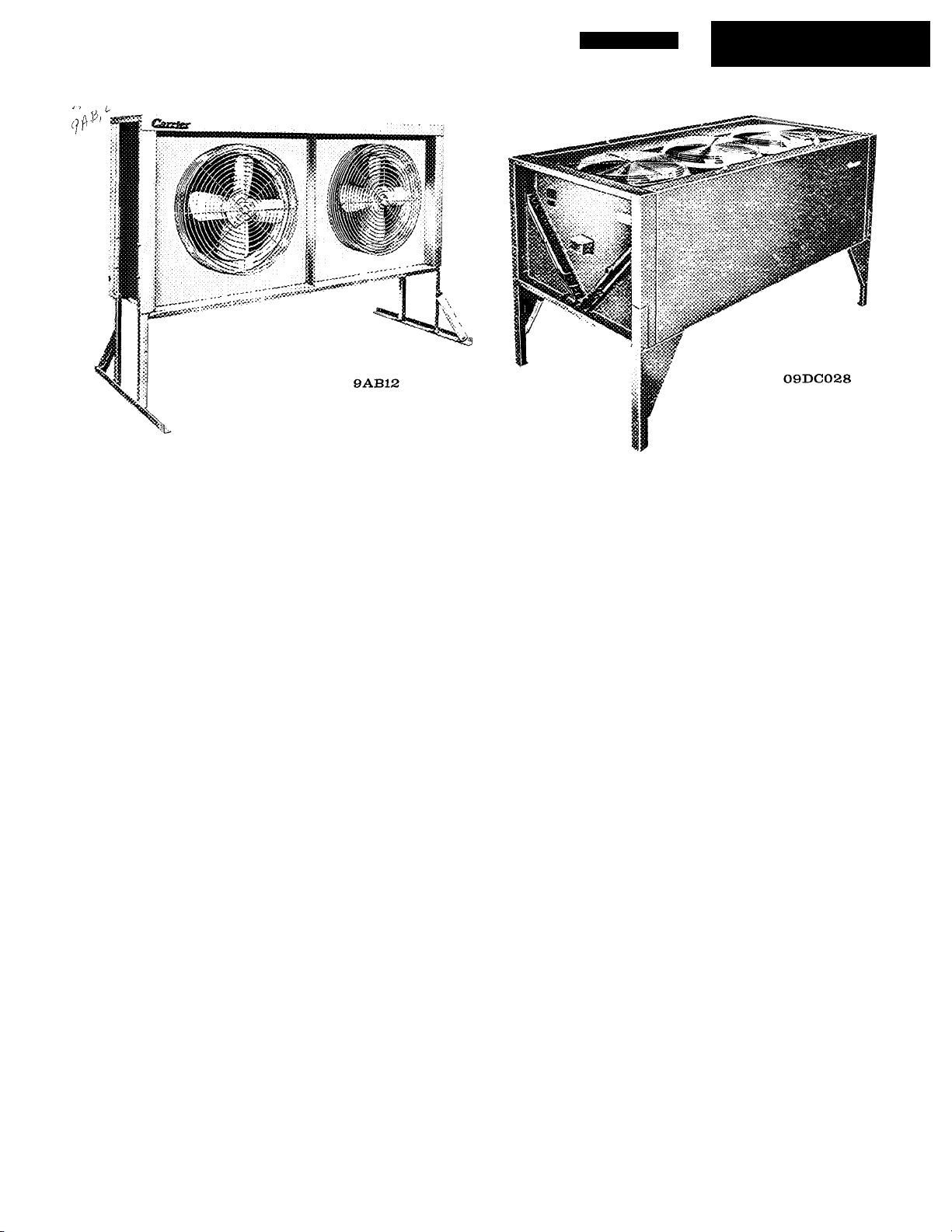
DESCRIPTION
Capacities to 10 Tons
9AB Air-Cooled Condensers available in nominal
capacities of 5, 7% and 10 tons are designed for verti
cal installations with horizontal air flow. They may be
located in any area having unobstructed air circula
tion; the low silhouette permits installation in varied
ground or roof locations. Each unit consists of a direct
drive motor (or motors), fan (or fans), fan guards,
motor mounts, condenser coil with integral subcooling
circuit, wind deflector, and electrical junction box.
Weather Armor* enclosures (which are also provided
for 09DC016) have a baked enamel finish which pro
vides maximum weather protection.
FEATURES
• Multiple Fans and Motors provide inexpensive, re
liable system control in intermediate seasons. Standby
protection is provided in case one fan motor fails.
• Subcooling permits greater liquid lift in vertical
risers without liquid flashing. Special coil circuiting
cools liquid refrigerant below the saturated condensing
temperature, extending system capacity without in
creasing motor horsepower.
• Direct Drive Fans require no tensioning device or
pulleys. Alignment problems, belt maintenance, and
friction loss are eliminated.
• Three Types of Head Pressure Control (Accessory)
are available to maintain a refrigeration load by hold-
Air-Cooled Condensers
Capacities 15 Tons and Over
09DC Air-Cooled Condensers are available in 15-,
20-, 25-, 30- and 40-ton sizes. The 25-, 30- and 40-ton
sizes are designed for use in multiples to give capacities
of 50, 60 and 80 tons. Each size has three direct drive
fans, three motors and motor mounts, three guards,
a junction box, and a condenser coil with integral sub
cooling circuit. The 20-, 25-, 30- and 40-ton units, all
using vertical air flow, may have 2 or 3 circuits, each
with an integral subcooling circuit. Each circuit may
be used as a separate condenser for a single system.
Double-weight, hot dipped, galvanized steel enclosures
give maximum protection.
ing a minimum head pressure and reducing condenser
capacity at low outdoor temperatures.
1. Motormaster Electronic Control (9AB6, 8, 12 and
09DC016, single-phase) modulates condenser fan
motor speed from zero to full rpm.
2. Fan Cycling Control cycles one fan (9AB8, 12) or
two fans (09DC) for control during intermediate
seasons.
3. Head Pressure Control Damper (09DC024, 084),
mounted below unit at the uncontrolled fan section,
further reduces capacity.
• Winter Start Control — Optional package permits
start-up of compressor regardless of low temperatures.
© Carrier Corporation 1966
•SINGLE FEATURE SHEET AVAILABLE
Form 9AB, 09DC-2P
Page 2
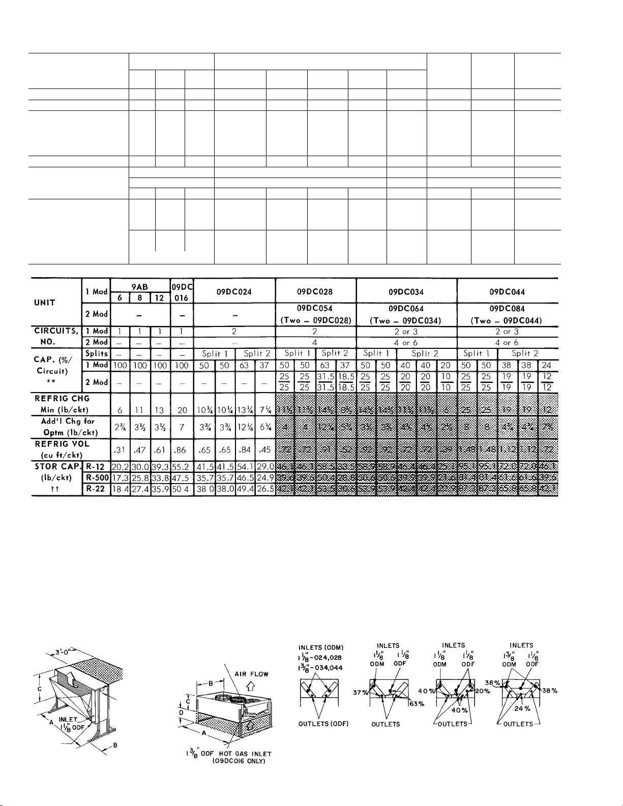
PHYSICAL DATA
UNIT
RATING (tons)*
NET WEIGHT (lb)t
FAN (Prop.), No.
Prop. Diom (in.)
Rpm
Cfm
MOTORS, No. ... Hp
COILS, Type
No.
Face Area (sq ft)
DIMENSIONS (ft-in.)
Length (each) A
Width (module) B
Height, w/o Legs
Adj Stand (in.) D
9 AB
6 8 12 016
6.8 10.5 13.8
215 315
1
22
1120
410
2 2 3
22 22
1 120
1120
4400 6600 8800
2...Vs 2... Vs
1.. Vs
3-row
1
9 0
3-7Vs 5-2 Vs
13 5
18 0
6-8Vs
3-1 Vs 3-1 Vs 3-1 Vs
C
3-2Vi6
lOV or
3-2 Vs
3-2Vs
16 V.
09DC
024
15.8
22.1
550 854
028
28.0
904
3 3
22 26
1120
13,000
3...V
1140
18,200 25,200
3...%
30
1140 1140
3 . 1
3-row
2
26.2 35.4 39 0 49.6
6-9Vs
4-6 V.
9- 7% 9- 1% 9- 7V.
3-1IV.
3-1IV. 4-lOV.
1-8V. 2- 4 Vs 2- 4 Vs
12Vsor 19Vs 16 or 24
16 or 24
09DC054
034 044
35.8 46.7 56.0
1225
1600
3 3 6
30 32 30
1140 1140 1140
28,200 31,000
3...1 3...1
4-row
2
60.4 78 0 99 2
9-lOV.
9-lOVst
6- OV. 3-1IV.
3- iVs
18 or 26 20 or 28
3- r/s
16 or 24 18 or 26
(T wo
028’s)
(Two
034*s)
71.7
09DC064
1808
2450
6 6
30
50,400 56,400
6...1
6...1
3-row
4
9- 1% 9- 7%
4-lOV.
2- 4 Vs
3- iVs 3- r/s
09DC084
(Two
044’s)
93.4
3200
32
1140
62,000
6...1
4-row
4
120.8
9-lOV.
9-lOVst
6- OV.
20 or 28
Data common to 1- and 2-module units.
*Tons of refrig effect at 30 F temp diff with 1 20 compr heat rejec
tion factor for R-22.
tWithout damper or refrigerant.
iFor three-circuit coil.
DIMENSIONS
9AB6,8,12 09DC016, 024, 028,
034, 044
5/„ ODF LIQUID OUTLET
“ (09DC0I6 ONLY)
AIR FLOW
ELECTRICAL
KNOCKOUT
OUTLET
'''a' ODE
S3 SPACE FOR AIR FLOW
**Use 50/50 split for single circuit. 09DC034 coil 40/40/20 split
may be field modified into 40/60 split.
tt80% liquid, 20% vapor at 90 F.
NOTES:
1. For 09DC024 thru 084, use maximum adjustable stand height
when using a damper section.
2. Certified dimension drawings available on request.
024,028.034,044
50/50
COIL SPLIT
1/2-024,028
7/"-034, 044
024,028
63/37
COIL SPLIT
ODF
RIGHT END VIEWS
7/^' ODF Vg" ODF
034
40/40/20
COIL SPLIT
044
38/38/24
COIL SPLIT
7/g ODF
Page 3

CONDENSER RATINGS TYPICAL ARRANGEMENTS
(Two-Module Condensers)
la. Select minimum or optimum charge ratings.
Use optimum charge when compressor, condenser, and
evaporator may be selected as a package and the com
ponents may be balanced* to secure maximum benefits
of 15 F subcooling (for example, in selecting 09DC con
densers with Carrier compressors rated at 15 F sub
cooling). Optimum charge activates the subcooling
circuit, resulting in higher system capacity at slightly
higher head pressure and corresponding condensing
temperature. Liquid refrigerant leaves the system sub
cooled to a stable condition to allow greater length of
refrigerant run or lift.
Otherwise, use minimum charge which gives higher heaf
rejection, since entire surface of condenser and sub
cooling circuit is used for condensing only. Minimum
charge ratings, however, do not represent greatest po
tential system capacity. They are comparable to com
petitive ratings without subcooling.
b. List the refrigerant, total heat rejection (THR), suction
and discharge temperatures as determined from com
pressor data.
2. Determine condensing temperature (saturated discharge
temperature minus discharge line loss).
3. Determine temperature difference (condensing tempera
ture minus entering air temp).
4. Enter Condenser Ratings table (minimum or optimum
charge as determined in Step 1) at selected refrigerant
and established temperature difference. Read across
to total heat rejection equal to or greater than required.
Interpolate if necessary. Read unit size.
Example (Optimum Charge)
1. Given:
R-22, Optimum Charge
THR (including subcooling)
Saturated Disch Temp................................................................................123.8 F
Saturated Suction Temp..................................................................................40 F
Entering Air Temp............................................................................................95 F
Disch Line Loss.................................................................................................2 F
2. CondTemp^ 123.8F-2F= 121.8F
3. TD = 121.8F-95F- 26.8 F
4. Interpolate in Condenser Ratings table (optimum charge)
and obtain capacity of 09DC028 as 30,0 tons and 09DC024
as 23.6 tons. Select the 09DC028.
..........................................................
29.4 Tons
Example (Minimum Charge)
1. Given:
R-12, Minimum Charge
THR . . ■
....................................................................................
Saturated Disch Temp...................................................................................122 F
Saturated Suction Temp..................................................................................40 F
Entering Air Temp...........................................................................................95 F
Disch Line Loss ............................................................................................2 F
2. Cond Temp = 122 F-2 F - 120 F
3. TD= 120 F-95 F-25 F
4. Enter Condenser Ratings table (minimum charge) and
select 09DC016 with 15,2 tons THR. (Note that with
optimum charge this unit has THR of 14.8 tons which
does not meet specifications).
*See Carrier System Design Manual.
15.0 Tons
Page 4

HEAD PRESSURE CONTROL
General — Efficient operation of evaporator expansion
valves requires a 90 F minimum condensing temperature for
100% compressor capacity, 80 F for 75% capacity, and 70 F
for 50% and 25% capacity. The capacity of an air-cooled
condenser increases with increased temperature difference
(cond temp minus entering air temp) and decreases with
decreased temperature difference. Therefore, a drop in en
tering air temperature lowers the condensing temperature
for a given heat rejection. When outdoor air temperatures
drop below prescribed minimums, some form of head pres
sure control is required. (See Head Pressure Control Data
table for minimum outdoor temperatures and specific head
pressure controls for 9AB and 09DC units.)
9AB, 09DC Head Pressure Controls — Head pressure on
9AB and 09DC condensers may be controlled by the Motor-
master Electronic Control, by fan cycling, or by fan cycling
supplemented by the Motormaster or a modulating damper.
Motormaster — When outdoor temperatures are low enough
to cause low condensing pressures, the Motormaster modu
lates the motor speed of one condenser fan from full to zero
rpm to maintain a constant saturated condensing tempera
ture. The Motormaster, available only with single-phase
motors (on unit sizes thru 09DC016), may be the sole con
trol on single fan units or may be used in conjunction with
fan cycling control on multiple fan units for full year-round
head pressure control.
Fan Cycling — The fan cycling control, used primarily
during intermediate seasons, cycles one fan or two fans.
On two-module condensers (09DC034, 064, 024), the fan
cycling control cycles four of the six condenser fans (two
of three in each module) from a two-step thermostat respond
ing to variations in ambient temperature. The first step of
the thermostat cuts out two corresponding fan motors, one in
each module; the second step cuts out a second pair of cor
responding fan motors. The two condenser modules are
controlled from a single, completely wired fan cycling con
trol box consisting of one two-stage thermostat, one power
and one control terminal block, and two quick-connect re
ceptacles (one at the end of a 10-foot flexible conduit).
HEAD PRESSURE CONTROL DATA
HEAD
UNIT
SIZES
All
9AB6 Motormaster
^ABS,Ï2
9AB8,12
024j,028,
OH 044i
09DC016
09DC024,
028, 034,
044t
PRESSURE
CONTROL
Far\
Ort i'<>>
Fan Cycling,
One Fan with
Motormaster
Tw«^ FiTK,
Fan Cycl ing,
Two Fans with
Motormaster
Fan Cyc 1 ing,
With Mod Damper
Winter Season
None
С/с''в^ j,
Two Fans
TD
30
25
20
30
25
20
3Q
2S
20 :
30
25
20
: 30
: 25
ГС
30
25
20
30
25
20
Ш
TD - Temperature Diff (cond temp minus ent air temp)
* Interpolation permitted.
t Based on 90 F minimum cond temp at 100% capacity, 80 F at 75%
and 70 F at 50% and 25%. (Motormaster holds cond temp to 100 ±
10 F at all loads and at temperatures down to -20 F.) On some ap
plications with multiple DX coils, the compressor may be unloaded
while individual coil(s) are still fully loaded. In this case, expan
sion valve selection must be based on condensing temperatures
listed, or the minimum outdoor air temperature must be raised by
the difference between listed cond temp and cond temp used for
valve selection.
t Applied also to each module of 09DC054, 064 and 084.
COMPR CAP. (%)*
100 75 50 25
Min Outdoor Temp (F)t
57
61
65
-20 -20
38
42
45
4?
5i
52
-20 -20
26
30
! m
55
57
60
60
65
70
-20
1 S3 i
43
52
-20 -20
3
1 4'i
-20 -20
-20 -20
-20 -20
-20-213
62
64
65
-20
'S3
43
S2 SS
25
SCHEMATIC WIRING DIAGRAM
— CONDENSER CONTROL
(Single Refrigerant Circuit, Single Phase)
Head Pressure Control Damper — An accessory head
pressure control damper is available to supplement the
fan cycling control on the 09DC024 and larger units. The
09DC054, 064, and 084 require two damper packages in
stalled for parallel throttling of air to the two uncontrolled
fans. Each damper assembly has a pressure-operated actu
ator to operate the damper blades which modulate inlet air
flow to the uncontrolled fan in response to head pressure
variations. The pressure sensing tubing (capillary) for both
pressure actuators is connected to the same point in the
liquid line serving the last refrigerant circuit to shut down.
Each capillary is provided with a 1/4-inch flare connection.
A single shut-off valve at the liquid line is recommended,
for service.
Multiple Circuit Condensers — Multiple circuit conden
sers applied to separate refrigeration cycles present special
problems when head pressure is controlled from a single
control point. For such applications, more positive system
control may be ensured by using individual condensers and
head pressure controls.
LP — Low Pressure Switch ^
HP — High Pressure Switch
NOTES:
1. For three-phase service, holding coils are wired in parallel.
2. Multicircuit units may be similarly controlled by wiring fan motor
holding coil(s) in series with thermostat, compressor overloads,
and low pressurestat of each refrigerant circuit
3. Two or more condensers, piped in parallel on a single refrig
erant circuit, must be of equal size and wired in parallel.
Page 5

SCHEMATIC WIRING —HEAD PRESSURE CONTROL
ТШЙЙОЗТЙТ i i
COMMON FOR
ALL WIRING
JiNTERLOCKED
[FC
[with СОМРЙ
■9AB WITH MOTORMASTER
,^5-9AB8,12 fan cycling ONE FAN / MOTORMASTER
iSl+m - 09DC0I6 FAN CYCLING TWO FANS/MOTORMASTER
CONTROL TERMINAL BLOCK
(FAN CYCLING CONTROL BOX)
2-STAGE
THERMOSTAT
FAN CYCLING TWO FANS (EACH MODULE) 09DC0I6, 024.028,034,044
QUICK-CONNECT
INTERLOCKED
WITH COMPR
BULB
LOCATED IN
AIRSTREAM
OF FM|
PLUG -Л
208/230/ i
TO fUSED DISCONNECT
3-PHASE POWER
TO FUSED DISCONNECT
\
FC| [
FM|)
" ; 1
____
a;
FM,
___
hi
1 i
u
FC2
FC3
'I'
POWER
TERMINAL
BLOCK
(FAN
CYCLING
CONTROL
BOX)
QUICK-CONNECT_J
PLUG
FM|
(FM^
(FM3,
“i±:
TO FUSED DISCONNECT
_FLEXIBLE
CONDUIT
(PART OF
FAN CYCLING
CONTROL BOX
PACKAGE)
208/230 V
LEGEND
— Fan Contactor
— Fan Motor
Ad(d this wiring
for 054,064,084
TYPICAL PIPING AND WIRING CONNECTIONS (09DC Units shown)
l-CIRCUIT
FUSED DISCONNECT SWITCHES
FROM POWER SOURCE
3 WIRES (Зф) OIG, _
024,028,034,044
2 WIRES(lф)OI6
1
NOTES:
1. Single-phase motors (9AB, 09DC016) require one field-supplied
contactor to start all fans. Three-phase motors (09DC016, 024,
028, 034 and 044) require one field-supplied contactor for each
fan unless supplied with accessory fan cycling control.
2. All pip ing between two mocdule units is fielid supplied.
3. Wiring and piping shown are general points-of-connection guides
only and do not include detai is required for specific instaI lotions,
4. All wiring must comply with appl ¡cable notional and local codes.
HOT GAS
2-CIRCUIT
ACCESSORY FAN
CYCLING CONTROL
(INCLUDES CONTACTORS;
THREE-PHASE)
JUNCTION BOX
LIQUID TO EVAPORATOR
WIRE AS IN EITHER
OF ABOVE DIAGRAMS
3-ClRCUIT
ACCESSORY DAMPER
SECTION 024, 028, 034
"3
LIQUID
All piping must follow standard refrigerant piping practices.
Piping to two-module units (09DC054, 064 and 084) should
follow standard proctice for multiple condensers. See Carrier
System Design Manual for details.
For pressure relief requirements, see latest revision of Safety
Code for Mechanical Refrigeration - ASA-B9 1.
AND 044 (USE ONLY WITH
FAN CYCLING CONTROL)
Page 6

ELECTRICAL DATA (60-cycle)
UNIT
9AB6
9AB8
9AB12
09DC016
09DC024
VOLTS
208/230
208/230
208/230
208/230
208/230
208/230
208/230
460
575
208
230 3
460
575
208 3
PHASE
09DC028, 230 3
034, 044
460
575 3
1
1
1 2
1
1
1
3
3 1.0
3 4 0
3
3 1.6
3
FANS FLA
No.
1
2
T otal
T Ota 1
3
T otal
1
1
1
1
1
2
3
3
3
Hp
(ea)
2 1*
V3
2.1*
V3
2.4
/3
2.1*
V3
2 4
%
V3 3 3*
4 0
V2
1 2
V2
3 8
/4
1.9
5 3
4 8
2 4
1 9
FLA - Full Load Amps
*These are special motors suitable for use with Motormaster head pres
sure control.
NOTE:
All 208/230-volt single-phase units are suitable for operation on either
voltage.
GUIDE SPECIFICATIONS
Furnish and Install as shown on the drawing—^—air
cooled condensers suitable for tons each of total
heat rejection, when condensing refrigerant at , F
saturated condensing temperature with air entering at«
F dry-bulb temperature. Units shall be arranged for hori
zontal (vertical) air flow.
Units shall consist of: coils, with integral subcooling, 2.
supporting casing with stand, and wind deflector (9AB only).
Coil shall be constructed of plate aluminum fins on mechani
cally expanded copper tubes, cleaned, dehydrated, sealed,
and leak tested at 400 psig (9AB), 410 psig (09DC016), or
420 psig (09DC024 and larger).
Fans shall be direct drive, propeller type, protected by
guards. Motors shall be permanent split-capacitor (9AB,
09DC016) or 3-phase, 60-cycle (09DC016, 024, 028, 034,
044, 054, 064, 084). All motors shall be resiliently mounted
and prelubricated, with built-in overload protection. Fan
shaft shall be corrosion protected and mounted in prelubri
cated bearings. Fan blades shall have an iridite finish. A
magnetic contactor shall be field supplied for 9AB, 09DC- 3.
016, and shall be field supplied for 09DC024, 028, 034, 044,
054, 064, 084 if head pressure control is not used.
Casing shall be painted, Galvanneal steel (9AB, 09DC-
016) or heavy-gage, double-weight (2-1/2 oz zinc/sq ft)
galvanized steel (09DC024, 028, 034, 044). Access panels
shall be provided for electrical connections.
Accessories (To specify from Items 1 thru 4 below, refer to 4.
Head Pressure Control Data table.)
1. Motormaster Electronic Head Pressure Control — Units
shall be provided with a completely transistorized vari
able speed fan control to modulate unit capacity in re
sponse to variations in head pressure. The control en- 5.
Manufacturer reserves the right to change any
closure shall be weathertight and shall have Weather
Armor finish. Mounting hardware shall also be provided.
Control shall modulate fan motor speed from full to
zero rpm to maintain a saturated condensing temperature
of approximately 100 F at outdoor temperatures down
to —20 F.
Fan Cycling Control — Unit(s) shall be provided with a
control to cycle one of two fans (9AB8,12), two of three
fans (09DC016,024,028,034,044), or four of six fans
(09DC054,064,084), in response to outdoor ambient temp
erature. Control package shall include; thermostat and
remote bulb (9AB8,12); contactor(s), terminal strip(s),
plug, and two-stage thermostat (09DC016,024,028,034,
044); contactors, two-stage thermostat, power control
terminal blocks and two quick-connect receptacles, one
at end of 10-foot flexible conduit (09DC054,064,084).
Controls shall be enclosed in weathertight sheet metal
box with cover. Necessary mounting hardware shall be
provided.
Head Pressure Control Damper — Unit(s) shall be pro
vided with a control for further reduction in condenser
capacity to meet system part load operation or lower
outdoor ambient temperatures. This assembly shall in
clude: flanged damper frame, movable damper blades,
operating linkages, self-contained pressure-operated
damper actuator with capillary, and necessary mounting
hardware.
Winter Start Control (required when minimum ambient
temperature is below design coil suction temperature) —
Unit(s) shall be provided with a Winter Start Control
Package which shall temporarily bypass the system low
pressurestat to permit start-up at low temperature.
Floor Mounting Stand (9AB8 and 12).
product specifications without notice.
CARRIER AIR CONDITIONING
Tab 5
Form 9AB,09DC-2P Supersedes 9AB,09DC-1P
COMPANY • SYRACUSE, NEW YORK
Printed in U.S.A.
2-66
Codes C and MC (520902)
 Loading...