

Page 1
Carrier
fnsfallatîon Instructions^^
Air-Cooled Condensing Units
(includes 50BD Combination)
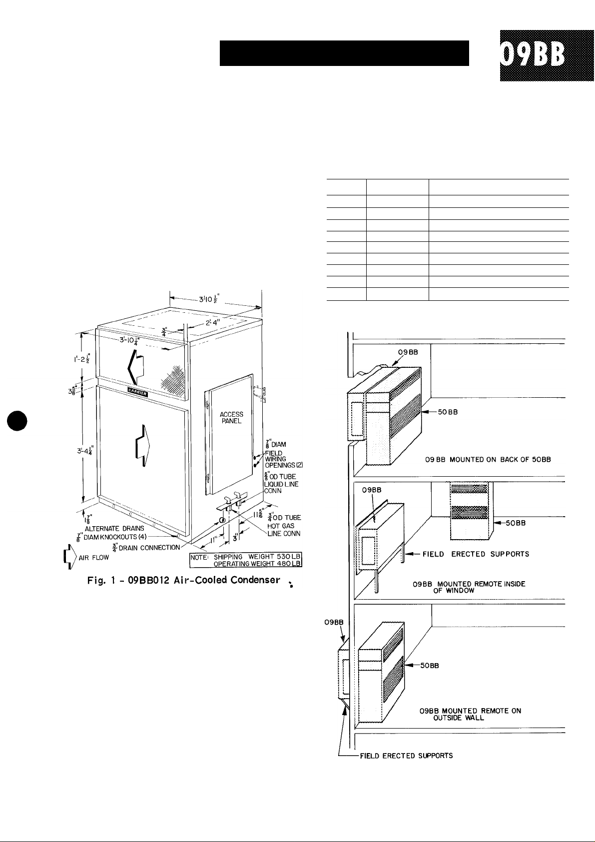
General - The 09BB012 condenser can be coupled
with a 50BB008 or 012 Weathermaker® unit to
form a 50BD combination.
The condenser is designed to match with, or
arranged to be field mounted to the back of
50BB units.
The condenser can also be mounted remote.
Air discharge can be vertical or horizontal, in
or out the same face.
Table 1 - Fastener Package Contents
UNIT
1
2
3 2
4
5
6
7 4
8 4
9
QUANTITY
4
2
2
2
2
2
Vibration isolators
Support bolt nuts 5/16-18
Channel bolts 3/8-16 x 1" hex hd
Lockwashers 3/8"
Plain washers 5/16"
DESCRIPTION
Locking bolt 1/4-20 1" hex hd
Support bolt 5/16-18 3" hex hd
Thd forming screws 1/4 x 1-1/4"
External locktooth washers 1/4"
Receiving the Unit ~ Inspect unit for shipping dam
age. Enter any claims directly with the transporta
tion company.
Carrier Air Conditioning Company will not be
responsible for damage incurred in transit.
Uncrating - Remove unit and hardware from ship
ping skid. Check to see that unit and component
parts conform to the bill of lading. Contents of
fastener package are listed in Table 1.
Before Installation - Check space requirements,
service clearances, floor strength, location of
piping, size of power supply, and location of duct
work (Fig. 2 and Fig. 3).
Make sure rigging equipment is adequate, Avoid
undue force against side and front panels when
lifting unit.
Carrier Corporation 1967
Printed in U.S.A.
Fig. 2 - Mounting Arrangements
6-67
09BB-1SI
Page 2
*1
V
Fig. 3 - 50BD Combination
©
Page 3

INSTALLATION
Mounting Brackets - Two mounting brackets are
supplied for mounting the 09 BB unit to the 50BB
unit (Fig. 4). These brackets have been designed
to provide adjustable heights for the 09BB to the
nearest 1/2 in. This is done by providing two sets
of mounting holes on the bracket, spaced 1-1/2 in.
apart. The upper mounting holes allow 09BB unit
height adjustment in 1-in. increments starting
1 ft 10-1/2 in. from the floor. The lower mounting
holes allow height adjustment in l-ir. increments
starting 2 ft from the floor.
Install brackets as follows:
1. Remove the top four retaining screws on each
side of the back panel of 50BB.
2. Select mounting holes and place bracket in
position. Install with retaining screws and
channel bolts in shipping holes (Fig. 4).
3.
Install support bolts as shown in Fig. 3.
4.
Install vibration isolators (supplied) in lowest
hole each side of 50BB back panel (Fig. 4). Re
move Tinnerman nut and install each vibration
isolator with 5/16 in. plain washer (supplied in
fastener package).
Vertical Discharge - 09BB unit can be mounted as
shown in Fig. 5. It will be necessary to relocate
the electrical junction box either external to unit
(as shown) or on an interior panel.
Also, provide a rain drain on back of unit.
Fig. 4 - Installation of Mounting Brackets
Positioning 09BB Unit
For typical installation
refer to Fig. 3.
WARNING: The 50EB unit will not balance the
09BB unit without additional support.
Once 09BB unit has been positioned in the
mounting brackets, install locking bolts as shown
in mounting bracket detail.
Before sliding units into final position, check
for clearance to access panels, and service area
to install piping.
PIPING
09BB hot gas and liquid line piping is factory
supplied when field mounting the 09BB to the 50BB.
The preformed piping is arranged for various
mounting heights. Cut the vertical rise of tubes
for height adjustment. No bending is required.
09BB units are factory charged with refrig
erant. Liquid and hot gas lines are installed
as follows:
Compatible Fittings - Liquid and hot gas lines are
installed from the 50BB unit to the 09BB unit with
Carrier compatible fittings and service valves.
These fittings may be used as sweat or mechanical
connections. Install either type as follows:
MECHANICAL CONNECTIONS
1. Cut tubing to length and remove burrs. Be care
ful not to expand tubing.
2. Remove plug from fitting and loosen nut one
turn.
3. Position tube. Remove cap and insert tube in
fitting to depth indicated on tag (1-1/4” depth
for 5/8” and 3/4” tube, 3/4” depth for 3/8”
and 5/16” tube).
4. Leave nut loose at condenser end of each tube.
Purge one line at a time using 50BB base unit
holding charge.
5. Tighten nut to a stop on unit fitting collar.
6. Open all service valves.
Page 4

SWEAT CONNECTIONS
1. Cut tubing to length and remove burrs. Be care
ful not to expand tubing.
2. Clean tubing. Remove plug and nut from fitting.
3. IMPORTANT - Remove O ring from inside
fitting. Wrap entire valve with wet rag.
4. Insert tubing in fitting and solder with lowtemperature solder (450 F) such as Allstate
430.
INTERNAL DRAINAGE - The base pan has a
3/4-in. coupling for an interior drain outlet (for
rainwater). Remove the plug from the drain out
let and install a trap in the piping if this system
is used.
IMPORTANT: For vertical discharge unit,
provide a rain drain on back of unit (Fig. 5).
On ail units, before connecting drains trim
away insulation blocking the hole{s).
NOTE: Make solder connection at 50BB
unit, then connect to 09BB unit except for
soldering. Purge with 50B3 holding charge,
then solder.
Brackets - After installing piping from 50BB to
09BB units, install the following:
HOT GAS LINE BRACKET - Install proper size
rubber-coated clamp assembly (furnished in 50BB
fastener package) to hot gas line bracket (Fig. 3).
CHANNEL AND PLATE ASSEMBLY - Figure 3
illustrates correct assembling and positioning for
this assembly.
Remote Piping - For 09BB remote installation,
select pipe sizes according to length from the
following table.
Table 2 - Remote Pipe Sizing (in.)
UINI 1
0-15 (ft) 16-25 (ft) 26-50 (ft) 51-75 (ft) 76-100 (ft)
50BB
008 3/4 5/8 7/8 5/8 7/8
012 3/4 5/8 7/8
HG — Hot Gas Line
Liq — Liquid Line
NOTES;
1. Normal number of elbows and fittings have been considered in
sizing pipes.
2. Pressure loss thru recommended hot gas line check valve has
been considered for 25-100 ft lengths.
3. Use of 0 hot gas line check valve is recommended on 50BB012
units with field-supplied piping.
HG
Liq
LENGTH OF PIPE
Liq
HG
7/8 1-1/8 7/8 1-1/8 7/8 1-1/8 7/8
HG
Liq
HG
5/8 1-1/8
Liq
7/8 1-1/8 7/8
HG
Liq
To connect piping, use instructions previously
given for compatible fittings. Use refrigerant
grade piping. If tubing size is other than unit con
nection sizes, use adapter fittings.
Refer to 50BB Installation Instructions to de
termine refrigerant charge adjustment for remote
piping.
Drains - The 09BB unit provides a choice of two
drain systems for installation. The choice is gov
erned by unit location.
EXTERNAL DRAINAGE - If unit is located with
front panel outside of building, there are four
7/8-in. knockouts that can be used for external
drainage (Fig. 1).
Pitch drain pipes downward for proper drain
age. Provide tees plugged one side for cleanouts.
Leave clearance for servicing. Observe local
sanitary codes.
For other piping details refer to Carrier Sys
tem Design Manual.
Ductwork - The 09BB unit is designed for use
without ductwork or rain louvers. If either is used,
care must be taken to eliminate air recirculation.
Recirculation can be minimized by blocking the
front discharge and discharging thru an extension
elbow. When properly designed, hinged discharge
louvers can be applied to ductwork, also to the con
denser air discharge. Fixed rain louvers over dis
charge outlets can cause excessive recirculation
and nuisance high-pressure switch cutouts. Ob
structions closer than 20 ft to the discharge air
pattern can cause significant recirculation.
If ductwork is used from standard discharge
openings and another "bird screen” is provided,
remove Carrier supplied screen to reduce static
pressure load.
CONDENSER AIR DUCT INSULATION
The condenser air duct must be insulated on
indoor installations to prevent moisture condensa
tion on the unit panels during cold weather. Insu
late as follows:
1. If metal ductwork is used, insulation should be
applied on the inside of the duct. This insulation
should be extended to cover the inside of the
09BB duct flanges.
It is necessary to insulate the inside of the
ducts at the duct flanges to reduce heat loss
from the metal cabinet by conduction thru the
duct flanges and into the cold duct. Interior
insulation allows the metal duct to approach
room temperature. It also prevents condensa
tion from forming and collecting under the in
sulation which will occur with exterior duct
insulation.
2. If insulation is applied to the outside of the
metal duct, the inside must be insulated for a
length of ten inches from the unit (including
the duct flanges) or up to the flexible duct
vapor barrier on the outside which must be
tightly sealed to prevent condensation under
the insulation.
Page 5

3. A high-density fiberglass (2 lb minimum den
sity) or semirigid foamed insulation such as
Styrofoam will be required inside the ducts to
prevent air erosion. The insulation must be
firmly secured in the discharge duct near the
blower discharge to withstand the high air
velocity.
Fan Adjustment - Check fan blade location before
start-up. Figure 6 indicates proper fan position
in relation to the fan orifice.
ELECTRICAL DATA
Fig. 6 - Position of Condenser Fan
TO DETERMINE WIRE SIZE USE
O Component Connections Unmarked
O Component Connections Marked
□ Terminal Board Connections
------
Field Wiring
Fig. 7 - Typical 50BD Wiring and Component Arrangement
LEGEND
C — Compressor Contactor
HPS - High Pressure Switch
F - Fan Contactor
FU - Fuse
HR - Holding Relay
5
LPS - Low Pressure Switch
TB - Terminal Block
TM - Timer Motor
Page 6

ELECTRICAL DATA (Cont)
MAINTENANCE
Refer to Table 3 for 09BB fan motor char
acteristics. Refer to Table 4 for wire and fuse
sizing. Refer to Fig. 7 for combination field
wiring.
Table 3 - 09BB Condenser Fan Motor
HORSEPOWER
1
FULL LOAD AMPS
7
Table 4 - Wire and Fuse Sizing
50BD*
COMBINATION
09BB012/50BB008
09BB012/50BB012
*When power is supplied to 09BB from 50BB terminal block, use
this table to size wires from fused disconnect to 50BB terminal
block.
t60° wire.
iBased on 1% voltage drop.
NOTES:
1. When power to 09BB is supplied from 50BB disconnect, refer
to 50BB Installation Instructions for wire sizes from fused
disconnect to 50BB
2. Power to 09BB can also be supplied from separate fused dis
connect. For this method, use 15 amp fuses and No 12 wire
3. Power supply voltage must be within ±10% of nameplate voltage.
VOLTAGE
(3-Phase,
60-Cycle)
208
230
208
230
LOCKED ROTOR AMPS
WIRE
SIZEt
(AWG)
WIRE MAX
LENGTH
(ft)r
6
4
2
6
4
2
4
2
4
2
140
117
175
100
119
18
MAX
FUSE
(Amps)
61
92
77
67
79
50
45
70
60
Cleaning - 09BB unit should be thoroughly cleaned
inside and out. Frequency of cleaning will depend
on unit location and area conditions.
Drains must be kept free of dirt and trash.
Coils can be cleaned with a stiff brush, vacuum
cleaner or compressed air. Coil can be reached
thru access panels.
Inspection - Check coil baffles for tight fit to pre
vent air from bypassing the coil.
Check panels for air leakage, particularly those
sealing the fan and coil compartments.
Check for loose electrical connections, oil
level, proper refrigerant charge and refrigerant
piping leaks.
NOTE: 09BB fan motor is permanently lubri
cated. Does not require further lubrication.
Before start-up, be sure all service valves ;
are open (backseated).
Tab 5 09BB-1S1 New
Manufacturer reserves the right to change any product specifications without notice
6-67 Codes C and MC Catalog No. 530-905
 Loading...