

Page 1
Carrier
installation, Start-Up ncsc H7F
and Service Instructions WOC,u/C
Compressors and Condensing Units
Hermetic, Water-Cooled
PRELIMINARY SURVEY
Inspect shipment for damage. File claim with
the shipping company if shipment is damaged or
incomplete.
Locate unit on floor in a well ventilated area.
Install unit where it will be warmer than condi
tioned area. Position it to allow sufficient space for
refrigerant and water connections and to service
compressor. Allow space at one end of condenser
for tube cleaning or replacement. Place unit so
suction and discharge valves can be easily reached
and so oil level can be checked.
Local water conditions can cause excessive
fouling or pitting of condenser tubes. If such
conditions are anticipated, a water treatment
analysis is recommended. Refer to Carrier System
Design Manual, Part 5, for general water condi
tioning information.
Make provision in piping layout to drain and vent
condenser if system is to be shut down in winter.
Level unit and bolt it firmly to foundation.
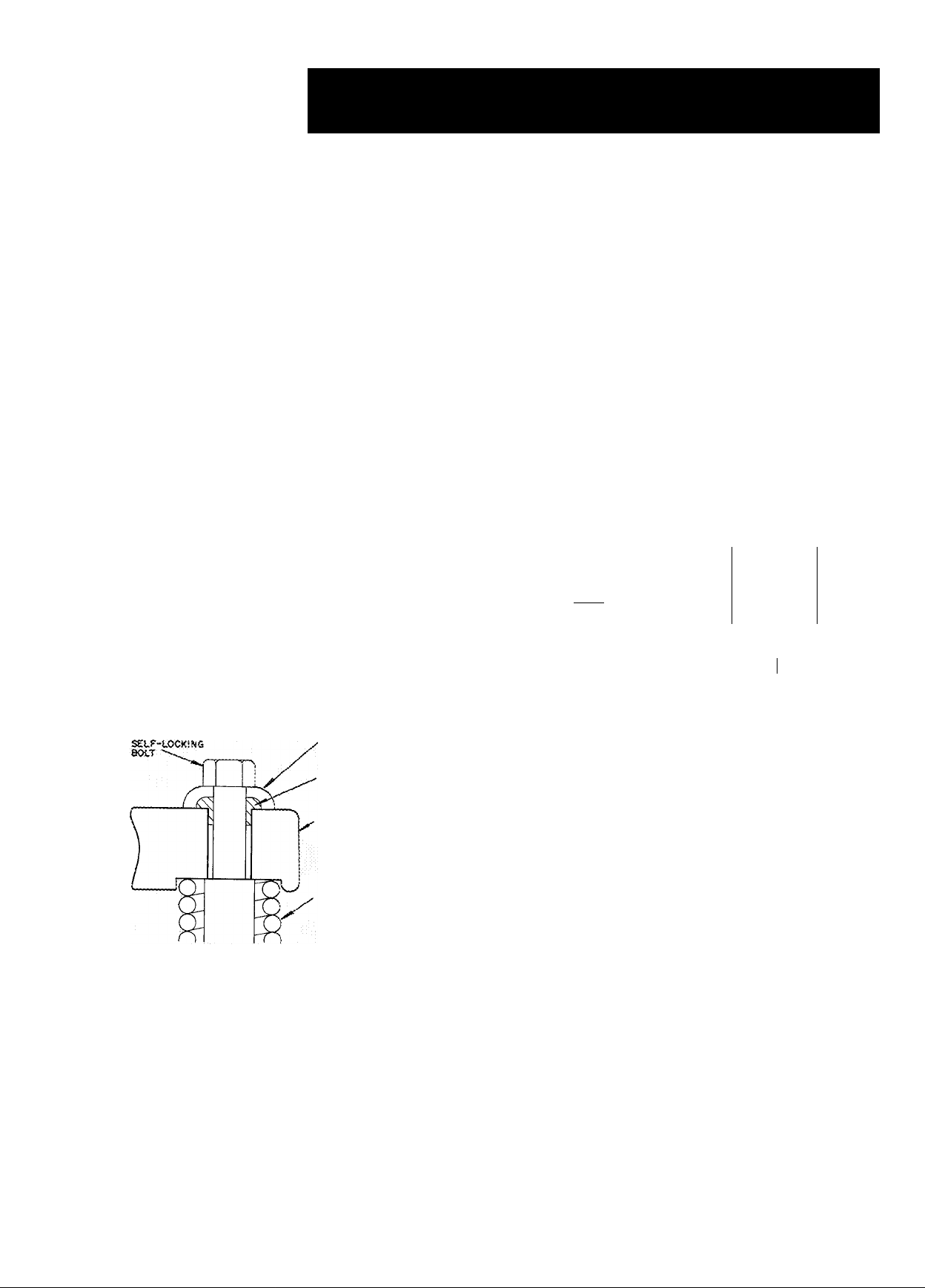
Remove 4 self-locking bolts from compressor
mounting springs, and reassemble them with
flanged washers and neoprene snubbers as shown in
Fig. 1. Flanged washers and neoprene snubbers are
shipped in a cloth bag tied to compressor. Tighten
all 4 bolts. Then, loosen each until the flanged
washer can be moved sidewise. Check compressor
to see that it floats freely on its mounting springs.
SMUBBER FLATBED
WASHER
MEOPRENE
SNUBBER
^COMPRESSOR FOOT
, tSOtATtON SPRiNO
Fig. 1 — Compressor Mounting
PIPING CONNECTIONS
Attach water supply and return line to connec
tions indicated on condensing unit (Fig. 3). Water
leaving condenser should not be connected directly
into sewer lines; check local codes.
Attach refrigerant liquid and suction lines to
condensing unit (Fig. 3); suction and discharge
lines to compressor unit (Fig. 2). Discharge line
muffler supplied with 06EV,W compressor units is
installed in discharge line as close to shutoff valve
as possible. When soldering or brazing piping to
valves, disassemble the valve or wrap it in wet cloth
to prevent damage by heat. Allow flexibility in
suction line so compressor suction valve may be
moved aside for access to suction strainer.
Install a solenoid valve (field supplied) in liquid
hne directly before expansion valve. Solenoid valve
is necessary for single pumpout control used on
06E,07E units (refer to Start-Up and Service
Instructions). A filter-drier of adequate size should
be installed in liquid line between condenser and
solenoid valve.
Pressure relief valve located on side of con
denser will open to relieve excessive pressure,
allowing refrigerant to escape. Most local codes
require piping from valve to outdoors.
Refer to Carrier System Design Manual for
standard piping techniques.
Table 1 — Physical Data
COMPRESSOR UNIT 06E
d P E R A fjNjG W E (G H T (fb)
CONDENSING UNIT 07E
OPERATING WEIGHT (lb)
refrigeYnt
COMPRESSOR 06E
Oil Charge (pt) (PP33-2)
Normal Oil Pressure*
Oil Safety Switch Cut-In
High-Pressure Switch
Cutout Range
Differential (cutout, cut-in) f
Factory Settings f Cutout '
Low-Pressure Switch
Cutout Range
Differential (cutout, cut-in)
Factory Settings! Cutout
Low Side Max Pressure
CONDENSER DATA
Max Refrigerant (R-22)
Storage Capacity (lb) t
Min Refrigerant (R-22)
Operating Charge (Ib)
Max Operating Pressure
Refrigerant Side
Water Side
J 07E Conidensing Unit data
* Pressures noted are above operating suction pressure; i.e , pressure
differential between suction pressure and discharge pressure of oil
pump.
Î Pressure switch settings shown are for R-22. When using other
refrigerants, reset high- and low-pressure switch settings to
pressures corresponding to satuialion temperatures indicated by
the above pressures.
\ Condenser 80% filled with liquid refrigerant at 104 F,
Cutout
Cut-in i
Cut-in
V022
W027 1 W033 W044
6Ô0
BO 22
D250
D150 N265 ;
B027^
1275 1340 1 1350
R-22, R-502^
14
230 to 400 psiq (adj)
23G to 340 p'ji ;g (ccj)
, 80 ± 10 psi (fi xed)
370 ± 7 Dsig
28C i
290 + 7 psig
200 ± 7 psic
20 in Hg vac to 60 psig (adj)
20 in Hg vac to 70 psig (adj)
31 psi (adj 13 to 50)
650
B033 D044
.1,
0265 I F 275 E299
N175
16 i Î9
psig
12-18
psig
8-10
psig
4- 5
36 + 4 psig
67 + 4 psig
245 psig
135
' 33
335 psig
250 psig
' 670
1560
N599
193
37
© Carrier Corporation 1972
Form 06E,07E-4SI
Page 2
E SUCTION VALVE ODF
(ROTATES 360°AT ,
90° INTERVALS)
* Install pressure relief device in discharge line
Pressure relief setting is 465 psig
tOverall width includes projection of fuse
holders and/or switches
j.Maximum height is to top of unloader valve on
06EV022 and W044
F DISCHARGE VALVE ODF^
'• . (ROTATES 180°) n
D DIAM CONCEN
DIAM-4 HOLES
RIG KNOCKOUT
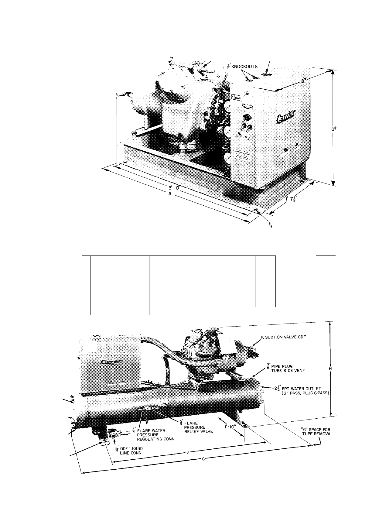
Fig. 2 — 06E Hermetic Compressor Units
06E Hermetic Compressor Unit Dimensions
UNIT 06E
DIMENSIONS (ff-in.)
CONNECTIONS (in.)
■k KNOCKOUTS .
2" FPT
OUTLET (6-PASS)
INLET (3-PASS)*
2 FPT INLET «”>■
(3-PASS*a6-PASS)~
V022
A
3-9V2
B
2-0 2-0
C
2-r/a 2-2Va
1% &
2V,
E
IVa
F
1 %
L DIAM CONCENTRIC
KNOCKOUT
W027
2-9%
2, 2%
& 3
IVs
1%
W033
3-11%
2- 0 1-1 1%
2- 1%
]% &
2%
2Va
1%
W044
4- 0%
2- 2
2, 2%
& 3
2Va
1%
07E Water-Cooled Condensing Unit Dimensions
2Va
2Va
D044
6- 7%
4-10%
2%a
2, 2Va
& 3
UNIT 07E
DIMENSIONS (ft-in.) G
CONNECTIONS (In.)
B022 B027 B033
6- 5 6- 5 6- 5
H
2-11% 2-1 r/2
J
4- 8%
K
L
1%
1% &
2%
4-IOV4
1%
2, 2%
& 3
2-1 1% 3- 2Va
4- 8%
1% &
I PIPE PLUG TUBE
SIDE DRAIN
EITHER END
DIAM-4 HOLES
WIDTH DIM I'-5"
ifc^TO
*Use both inlets for 3-pass operation.
Fig. 3 — 07E Water-Cooled Condensing Units
Page 3
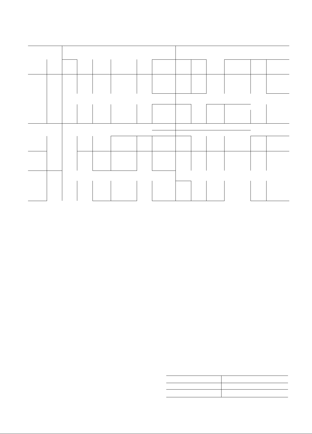
Table 2 — Electrical Data
volts/phaU
NDSV
COND
UNIT KW LRA FLA
07 E
B022
B027 31.4
B033 34 0
DO 44 50.4
COMPR
06 E
V022 24 8 387
W027
W033
W044 55.1
VOLTS/PHASE
NDSV
COND
UNIT KW LRA
07 E (AWG No.) Wire
B022
B027
B033 34 0 175 48 66 0
D044 50.4 265 61 85.4
COMPR
06 E
V022 24 8 175 35 48 3
WO 27
W033 37 6 210
W044 55 1 300 69 96.0
FLA — Full Load Amps
LRA — Locked Rotor Amps
IMDSV — Nominal Distribution System Voltage (Application Range)
OLTA — Overload Trip Amps
*Wire size to terminal box (line side)
NOTES:
1. 208-, 230-volt 06E compressor units and 07E condensing units
22 6
33.6 457
37 6
22 6
31 4
33 6 205 43 60 2
-- Motorsand controlswill operate satisfactorily 10% above
and 10% below the NDSV (Application Range)
have part-winding start 460-, 575-volt units have across-the-line
start, except 06EW044 and 07ED044 which have part-winding
start Control circuit voltage is 11 5 volts for all units.
310 71 99
457
387 105
586 126
464
664
FLA OLTA Size*
140
205
OLTA
86 121
78 109
93
115 160
137
32
44 5 8 102
41 57 8 6 122
52 71 6
208/3 230/3
208
Wire
Size*
(AWG No.)
146 00
176
129
192
00
00
00
460/3
440-480
Wire
4
6 143
6
4
2
0
1
0
2
2
Max Fusetron Wire
Ft
Wire
73 100
62 125
84
71 200 530
79
79 150 410
77 175 420
65
Max
Ft
158 70
132
116
145 75
121
220-240
Si ze
(Amps) (AWG No.)
150
110 350
200 600 137
Fusetron
Si ze
(Amps)
45
60 164
90 212 53 73.4 4 185
50 140 28 38 6
70
100 240 56 78 0
LRA
280 65 90 8
410
350 96 134 0 0
LRA
1 12
140 38 53 3 6 165 60
164 34
168
Factory wiring is in compliance with National Electrical Code.
Field wiring must comply with appiicable local codes Maximum
wire size to control center line terminal block is 250 MCM.
Where compressor FLA is under 100 amps, wire sizes are based
on type TW wire. Where compressor FLA is over 100 amps, wire
sizes are based on type TFIW wire
Maximum wire lengths tabulated will result in a 1% voltage drop
to compressor A 3% voltage drop is maximum allowed.Therefore,
the run length can be increased to three times the value given.
5.
Above 06E compressor unit electrical data does not apply for
06E compressors used as an integral part of other Carrier equip
ment See proper Start-Up and Service book for electrical
information
FLA OLTA
116 0
82
126 176.0 00
71
86
105 146
FLA
27 36 7 8 151
34 48 3
42
99
120
192 00
OLTA
48 3
58 0
Size* Ft Size
2
0
2 80 100
1 78
00
575/3
550-600
Wire
Size*
(AWG No.)
6 183
8 147 40
6
6 150 60
4 171 80
Max Fusetron
Wire
Max
Ft
Wire
183
(Amps)
88 100
78
87 150
80 200
94
72
125
125
150
200
Fusetron
Size
(Amps)
40
SO
80
50
ELECTRICAL REQUIREMENTS
Field wiring must comply with local and
national codes.
Install a branch circuit fused disconnect of
adequate size to handle starting current.
Line power is brought into control center thru
indicated opening. Connect line power supply to
terminal block 1; connect power leads to terminals
LI, L2 and L3. Connect control circuit power
supply (115 volt) to terminals 1 and 2 on terminal
block 2. Refer to Fig. 4 and 5.
Wiring connections for field-supplied equip
ment are shown on diagram attached to unit (or in
wiring diagram booklet).
Discharge line limit thermostat supplied with
06EV,W compressor units is installed on discharge
hne as close to compressor as possible.
1. Place mounting
plate on discharge line and
solder in place.
2. Fasten the thermostat
to plate with screws
supplied.
3. Cover switch with insulation and secure insula
tion at each end with straps.
4. Connect thermostat leads to control circuit
terminals 4 and 5.
ACCESSORIES
PACKAGE NUMBER DESCRIPTION
07EA900021 Control Circuit Transformer
07EA900001
Gage Panel
Page 4
KNOCKOUTS
DISCHARGE LINE
THERMOSTAT CONN
PART-WINDING
START UNITS
ONLY
CONTROL CIRCUIT
POWER CONN.*
(TERMINAL BLOCK
N0.2)
ACCESSORY
TRANSFORMER
CONNECT TO LI a L2
TERMINALS ON LINE
SIDE OF CONTACTOR
*Refer to unit label wiring diagram for connections when accessory
transformer or interlocks are used
Fig. 4 - Control Center - Used on: 06EV022, 06EW033, 07EB022, 07EB033
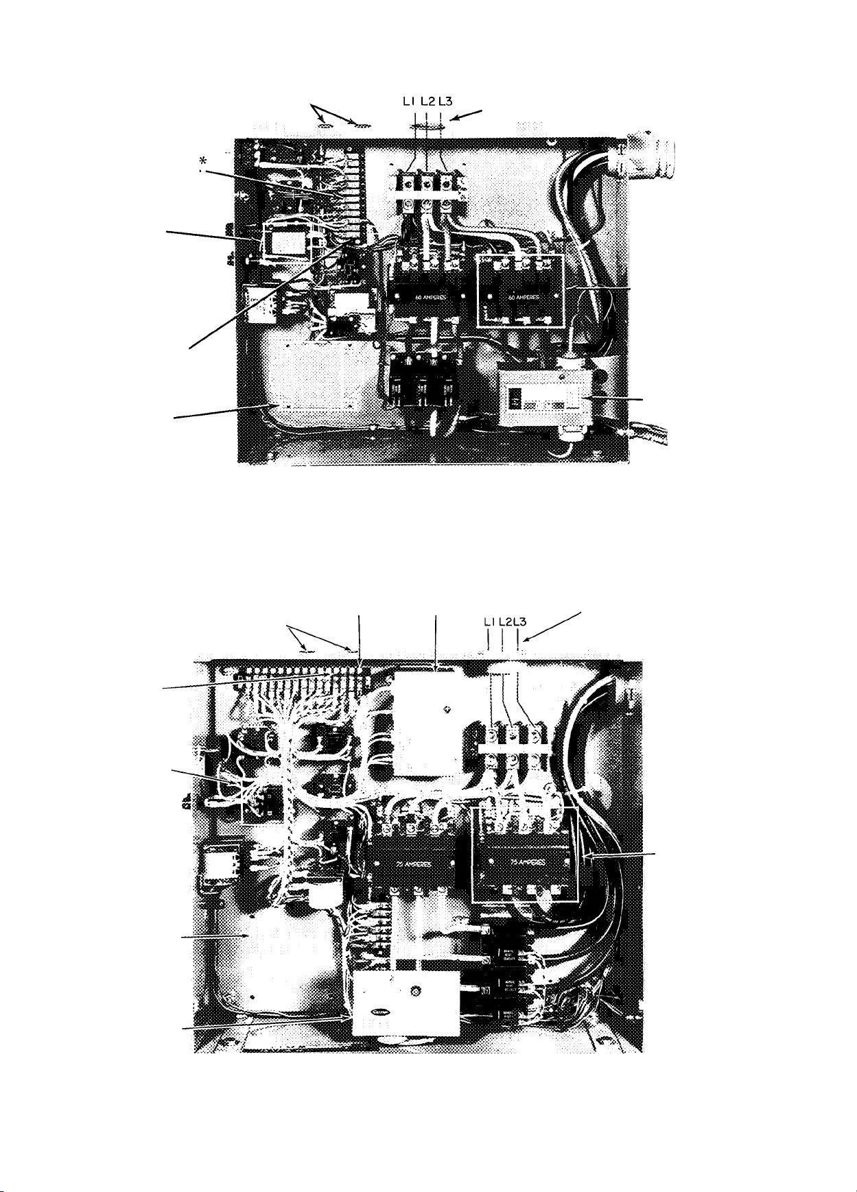
FIELD POWER CONN.
(TERMINAL BLOCK NO. I)
PART-WINDING
START UNITS
ONLY
OIL PRESSURE
SAFETY SWITCH
DISCHARGE LINE
THERMOSTAT
CONN.*
PART-WINDING
START UNITS
ONLY
ACCESSORY
TRANSFORMER
CONNECT TO LI
a L2 TERMINALS
ON LINE SIDE OF
CONTACTOR
KNOCKOUTS
MOTOR PROTECTION MODULE
CONTROL CIRCUIT
POWER CONN.*
(TERMINAL
BLOCK N0.2)
FIELD POWER CONN.
(TERMINAL BLOCK N0.1)
PART-WINDING
START UNITS
ONLY
OIL PRESSURE
SAFETY SWITCH
*Refer to unit label wiring diagram for connections when accessory transtoriT.er or
interlocks are used
Fig. 5 - Control Center - Used on: 06EW027, 06EW044, 07EB027, 07ED044
Page 5
REFRIGERANT CHARGING
Evacuate, ' Dehydrate and Leak Test the entire
refrigerant system by methods described in Carrier
Standard Service Techniques Manual, Chapter 1,
Sections 1-6 and 1-7. Use sight glass method to
charge system. See section 1-8 of Service Tech
niques Manual for details.
CHARGE THE SYSTEM to a clear sight glass while
holding saturated condensing pressure constant at
125 F (air-cooled systems) or 105 F (water-cooled
systems). Add additional refrigerant to fill con
denser subcooler coils.
07E Condensing Units
obtained.
add charge
After clear sight glass is
until liquid refrigerant
reaches condenser liquid level test cock.
06E Compressor Units — See condenser data for
additional charge required to fill subcooler.
INITIAL START-UP
Crankcase heater should be energized a mini
mum of 24 hours before starting unit.
Check to see that oil level is 1/3 to 2/3 up on
compressor sight glass.
Open water supply valve and allow water to
reach condenser. (Turn condenser fan on when the
compressor unit is applied with air-cooled
condenser.)
Backseat the compressor suction and discharge
shutoff valves; open liquid line valve at receiver.
Start evaporator fan or chilled water pump.
To Start Compressor, place control center start-
stop switch in “Start” position, and push motor
protector relay start-reset button. (Time Guard
circuit will cause a short delay before compressor
starts.) If compressor does not start in a 5-minute
period, reset oil pressure safety switch and over
load relays.
Recheck oil level and check oil pressure which
should be 12-18 psig above suction pressure.
NOTE: If compressor is shut off by motor
protection relay, current overloads, oil safety
switch or if control circuit power is opened, reset
button(s) must be pushed before compressor will
restart. Do not reset safety controls more than
once before determining cause of shutdown.
CHECKING OPERATIONS
Refer to Carrier Standard Service Techniques
Manual, Chapter 2 for complete instructions on
checking electrical components.
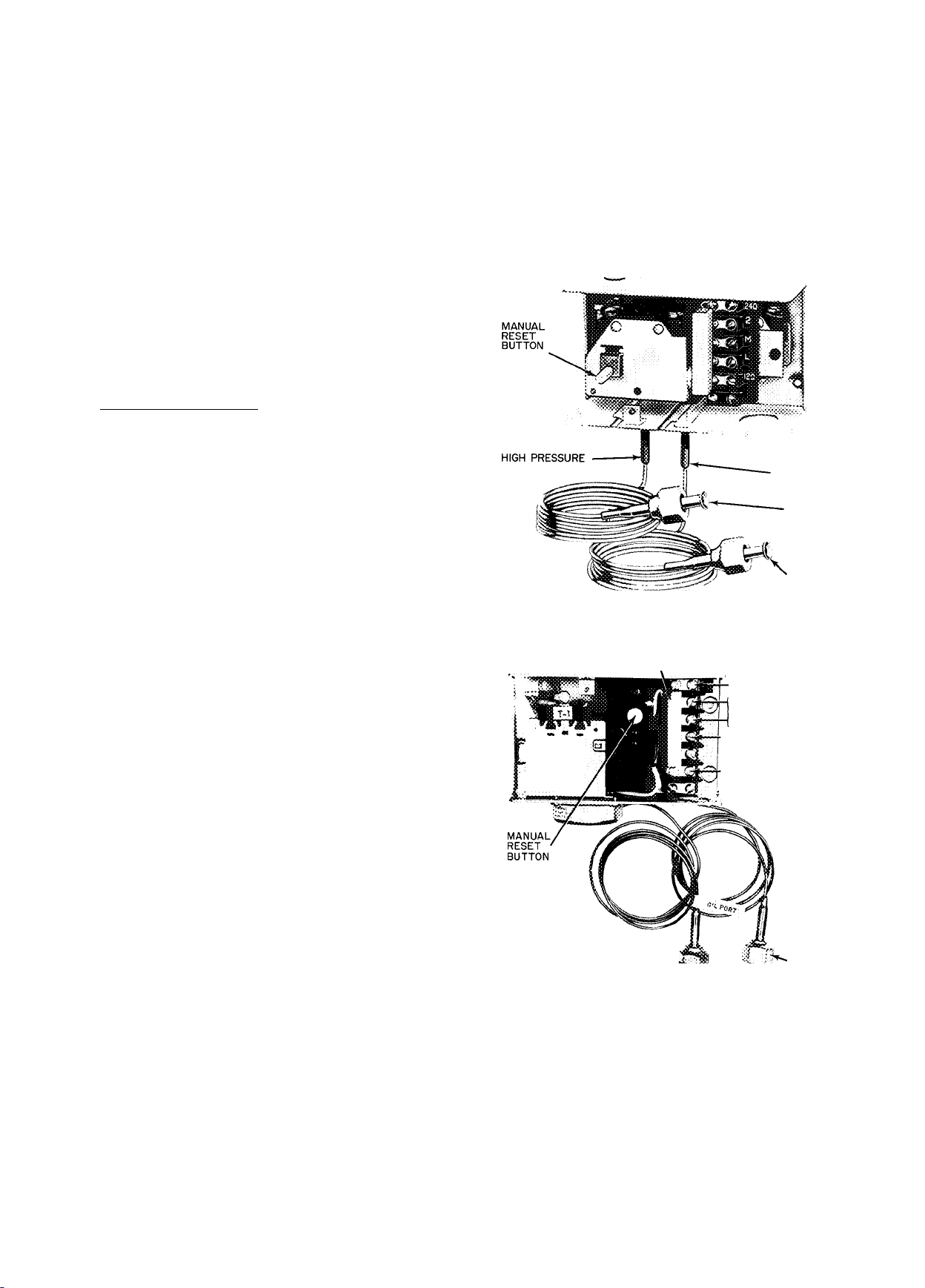
Oil Pressure Safety Switch (Fig. 6 and 7) may be
checked by moving arm on left side of switch
forward. Compressor should stop in approximately
45 seconds. (If compressor continues to run, check
wiring to safety switch. If wiring is correct, the
switch is faulty and should be replaced.)
After completing test, press reset button on
front of safety switch and restart compressor.
(Allow 3 minutes before attempting to reset
switch.)
NOTE Check oil level in compressor sight glass
after 15-20 minutes of operation. If oil level is low,
add oil according to methods described in Carrier
Standard Service Techniques Manual, Chapter 1
(Section 1-11).
LOW PRESSURE
CONNECT TO
OIL PUMP
DISCHARGE
CONNECT TO
(Switch shown is Penn Controls )
CRANKCASE
Fig. 6 — Oil Pressure Safety Switch Used on;
06EV022, 06EW033, 07EB022, 07EB033
RESISTANCE
I
■f
120
V^C
CONNECT IN 240
SERIES WITH VAC
CONTROL CIRCUIT
(REFER TO UNIT LABEL
WIRING DIAGRAM)
HIGH-PRESSURE
CONNECTION TO
0|LPUMP '" LOW-PRESSURE
DISCHARGE CONNECTION
TO CRANKCASE
Fig. 7 — Oil Pressure Safety Switch Used on:
06EW027, 06EW044, 07EB027, 07ED044
Dual Pressurestat (Fig. 8) — High-pressure safety
switch is checked by throttling condenser water or
blocking air flow on air-cooled units, allowing head
pressure to rise gradually. Check discharge pressure
constantly throughout procedure. Compressor
should shut off within 10 psi of values shown in
Table 1.
Page 6

Check low-pressure switch by slowly closing
suction shutoff valve or by completely closing
hquid line shutoff valve. A decrease of suction
pressure will follow. Compressor should shut off
within 4 psi of values shown in Table 1.
HIGH-PRESSURE
SAFETY SWITCH
DIFFERENTIAL ADJUSTMENT -TURN
■ № ■' CLOCKWISE TO DECREASE ONLY LOWER
SETTING WITHOUT CHANGING THE
HIGHER SETTING
*Hlgh — 38 PsI/Turn
Low — 7 Psi/Turn
Fig. 8 — Dual Pressurestat Adjustment
Time Guard Circuit for each compressor provides
LOW-PRESSURE
SAFETY SWITCH
RANGE ADJUSTMENT-TURN
CLOCKWISE TO RAISE BOTH
CUT-IN AND CUTOUT
for a 5-minute delay before restarting compressor
after shutdown for any reason. On starting, the
Time Guard Timer causes a delay of 15 seconds
after thermostat closes before compressor will
start. On compressor shutdown, the timer recycles
for 4 minutes 45 seconds. During this time the
compressor cannot restart.
Compressor Motor Protection on 06EW027,
06EW044, 07EB027 and 07ED044 consists of
three temperature sensors embedded in motor
windings and connected to a solid state module in
unit control box.
When an over-temperature condition causes
module to shut compressor off, push control
center STOP button. Investigate cause of com
pressor shutdown and correct. After compressor
cools (see Temperature Sensors below), push
ST ART-RESET button. Compressor will restart
after Time Guard delay period.
SOLID STATE MODULE is checked by applying
unit control voltage to terminals T1 and T2 (see
label diagram), then checking for continuity across
terminals Ml and M2. If no continuity between Ml
and M2, check temperature sensor and fuse resist
ance using a volt-ohmmeter (see below).
CAUTION; Do not use a fcattiary powered test
lamp to check sensors. Excessive current can
cause damage.
TEMPERATURE SENSORS are protected by
three 1/8-amp fuses (Carrier Part no. HYIOLFOIO)
in compressor terminal box. Fuse resistance should
be between 3.2 and 4.4 ohms. Replace defective
fuses only with 1/8-amp fuses specified above. If
all sensors check below 95 ohms (180 F), fuses are
good, and there is no continuity between module
terminals Ml and M2, replace module.
If one sensor fails, it can be jumpered out of
the circuit with a 75 ohm, 2-watt resistor across
the proper sensor terminal and common terminal.
If a short to ground in sensor circuit is indicated,
replace compressor motor.
CAPACITY CONTROL ADJUSTMENT
Control Set Point (cylinder load point) is adjust
able from 0 psig to 85 psig. Pressure differential
between cylinder load-up point and cylinder un
load point is adjustable from 6 psig to 22 psig.
To Regulate Control Set Point — Refer to Fig. 9.
Turn adjustment nut clockwise to its bottom stop
(with nut in this position set point is 85 psig).
Control set point is then regulated to desired
pressure by turning adjustment nut counterclock
wise; every full turn decreasing set point by 7.5 psig.
(Approximately 11-1/2 turns in counterclockwise
direction will decrease control set point to 0 psig.)
Table 3 shows the steps of control for the
compressor and condensing unit.
SEALING CAP
(CAP MUST BE REPLACED
TO PREVENT REFRIGERANT LEAKAGE)
Fig. 9 — Capacity Control Valve
Table 3 — Steps of Control
COMPRESSOR*
CONDENSING
UNIT*
06EV022
07EB022
06EW027
07EB027
06EW033
07EB033
06EW044
07ED044
^Capacity control valve (Fig 6) factory settings for 4-cylinder
units are: 69 psig control set point (cylinder load point), 10 psig
differential (59 psig cylinder unload point) Settings for
6-cylinder units are; leit cylinder bank control set point is
70 psig, differential is 10 psig; right cylinder bank control set
point is 68 psig, differential is 10 psig
—
No.
Cyl
4 100
6 100
6 100
6
1
%
Cap.
100 4
STEPS
No.
Cyl
2
4
4
2
%
Cap.
50
67
67
67
---------------
No.
Cyl
- -
2 33
2 33
2 33
-
3
%
Cap.
Page 7

Pressure Differential Adjustment — Turn differ
ential adjusting s,crew in counterclockwise direc
tion to its back-stop position (differential in this
position 6 psig). Pressure differential is set by
turning adjustment screw clockwise; every full turn
increasing differential by 1.5 psig. (Approximately
10 turns in clockwise direction will increase
pressure differential to 22 psig.)
acid cautiously. Clean condenser by gravity or
forced circulation (Fig. 10 and 11). For average
scale deposits allow acid solution to remain in
condenser overnight; for heavy deposits, allow 24
hours. Drain condenser and flush with clean water.
NOTE: Protect condenser from freezing when
ambient is below 32 F by draining water from
system or adding antifreeze to water.
CONDENSER MAINTENANCE (07E Units)
To inspect and clean condenser, drain water
and remove condenser heads. To drain condenser,
shut off water supply and disconnect inlet and
outlet piping. Remove drain plugs and vent plug.
With condenser heads removed, inspect tubes
for refrigerant leaks. (Refer to Carrier Standard
Service Techniques Manual, Chapter 1 Section 1-6,
Leak Testing, for instructions.)
Clean condenser tubes with nylon brush
(available from Carrier Service Department). Flush
water thru tubes while cleaning. If hard scale has
formed, clean tubes chemically. Do not use brushes
that will scrape or scratch tubes.
For chemical cleaning solution, use inhibited
hydrochloric acid solution (Oakite 32). Handle
C£NTfilFU<5AL <3AS VSNT30 GPM AT 35* BEAD GC03E
PUMP
SUCTION
PUMP^
SUPPORT
TANK-
PRIMING /VAUvesX
CONN, /
!
-RETURN
Fig. 11 — Forced Circulation
i CLOSE VENT PIPE
( VALVE WHEN
( PUMP IS
! RUNBiNG
REMOVE WATER
REGULATING VALVE
REMOVING, INSPECTING AND
REPLACING COMPONENTS (Fig. 12)
Service Notes
1.
Where compressor components are shown they
are in normal order of removal from compressor.
2.
All compressors have interchangeable valve
plate assemblies, unloader valves and oil pump
bearing head assemblies. For replacement items
use Carrier Specified Parts.
3.
Before compressor is opened, the refrigerant
must be removed from it by the Pumpdown
method.
a. Start compressor, close suction shutoff
valve, and reduce crankcase pressure to
2 psig. (Jumper low pressurestat.)
Table 4 — Torque Values
SIZE
THREADS
DIAM
(in.)
No. 6 32
No. 10
PER IN.
27 (pipe) 8-12
yi6
V4
‘/4
V4
18 (pipe)
%
18 (pipe)
\
Xe
Va
V»
%
%
18 20-25
20
28
16
14
13
11
18 60-75 Oi 1 Drain Plug
16 105 Stator Lock
32
TORQUE
RANGE
(ft-lb)
Pipe Plug — Crankshaft
Pipe Plug — Crankcase
8-10
Conn. Rod Cap Screw
8-12
Junction Box
3-5
14-18
14-18
14-18
15-24
15-24
30-40
30-40
30-40
25-30
30-40
55-65
55-65
100-120
90-120
90-120
90-120
90-120
Sight Glass
Oil Pump Drive Segment
Unioader Valve
Discharge Valve Stop
Cover Plate — Pump End
Bearing Head
Discharge Service Valve(4 cyl)
Bottom Plate — Crankcase
Compressor Foot
Terminal Block
Oil Plug — Pump End Bearing
2-4
1-2 Check Valve Body — Crankcase
4-6
4-6
Head
Terminal Bolts
Pipe Plug — Junction Box
Motor End Cover
Pump End Bearing Head
Cyl inder Head
Discharge Service Valve(6 cyl)
Suction Service Valve (4 cyl)
Suction Service Valve (6 cyl)
Rotor Lock — Crankshaft
Oil Pump Drive Segment
Terminal Screw
USAGE
Page 8

®®
'J /
^x V.
--------------
_ ?' i
^
@
06EV027, W044 AND 07EB022,033
: |-(S 1
^~® i
■•' 1
^ '
'■ .': mifr^ 1
{SEE LEGEND PAGE 9)
Fig. 12 — 06E Compressor Components
8
rfWIMMMh -- nji_i_ui_,
' ^ ' : ,3?^
^ .*,
Page 9

b. stop compressor and isolate from system by
closing discharge shutoff valve.
c. Bleed any residual refrigerant. Drain oil if
necessary.
4. After disassembly, clean all parts with solvent.
Use mineral spirits, white gasoline or naptha.
5. Before assembly, coat all parts with compressor
oil and clean and inspect all gasket surfaces.
Replace all gaskets with new factory-made
gaskets. See Table 4 for torque values.
6. After reassembly, evacuate compressor and
open suction and discharge valves. Restart
compressor and adjust refrigerant charge.
LUBRICATION SYSTEM
Testing Oil Pump — An oil pressure tap is located
above oil pump cover plate (Fig. 13). Oil pressure
should be 12 - 18 psi above suction pressure.
REMOVE 8 CAP SCREWS
OIL PRESSURE TAP
Compressor MotorStator and Rotor
Motor Key
©
Rotor Plate Washer
©
Rotor Lock Washer
©
Rotor Lock Bolt
©
Motor Lock Bushing
©
Roll Pin
©
Acorn Nut and Gasket
©
Ring Spacer
©
Junction Box
Fiame Arrestor
©
Terminal Plate Assembly
@
Terminal Bolt Assembly
0
Terminal Bolt Assembly
0
Terminal Bolt Assembly
0
Cover Plate
0
Hex Head Screw
©
Compressor Crankcase
0
Motor End Cover
©
Cylinder Head —
©
Center Bank
Cylinder Head - Ca
0
pacity Control Side Bank
Internal Relief Valve
0
Crankcase Oil Filter
0
Screen
Oil Sight Glass Assembly
0
Oil Sight Glass "O”
0
Ring Gasket
Oil Sight Glass Screw
0
Oil Sight Glass Lock
0
Washer
Pipe Plug Gasket
0
(hex head)
Bottom Cover Plate
(S)
Legend (Fig. 12)
(30) Pump End Bearing
(0 Pump Rotor
(3^ Pump Vane
(3^ Pump Vane Spring
(3^ Pump Vane Spring
(3^ Retaining Spring
(3^ Oil Feed Guide Vane
(3^ Oil Feed Guide Vane
(3^ Oil Pump Drive
(3^ Screw, Soc Head
^ 1/4 - 28 X 5/8 in.
(4^ Screw, Soc Head no 10
^ -32x1/2 in
(0 Cover Plate
(42) Cover Plate Cap Screw
(0) Crankshaft
(0 Bearing Washer
(0) Piston Ring (Oil and
(0) Piston, Piston Pin and
(0) Connecting Rod and
(0) Valve Plate Package
(0) Valve Plate
0) Discharge Valve Stop
(0) Discharge Valve
(0) Valve Stop Support
(0) Cap Screw, Valve Stop
(55) Suction Valve
Head Package
Guide
Spring
Segment
Oil Relief Piston
Compression)
Retaining Ring Package
Cap Assembly
PUMP END BEARING HEAD
ORIVE SEGMENT CAP SCREWS
Fig. 13 — Removing Pump End Bearing Head
OIL FEED GUIDE VANE
AND SPRING
COVER
PLATE
OIL FILTER SCREEN is accessible thru bottom
cover plate. Remove and inspect strainer for holes
and dirt. Clean it with solvent and replace.
Oil Pump and Bearing Head — The oil pump
assembly is contained in the pump end bearing
head aluminum casting. (The pump end main
bearing is a machined part of this casting — no
insert bearing.)
REMOVE bearing head from crankcase and
disassemble oil pump. Drive segment cap screws
must be removed before bearing head can be
removed (Fig. 13). Remove pump vane assemblies
from both sides of bearing head. Push the pump
rotor out of the bearing head by pushing against
the bearing side of the rotor. Check all parts
(Fig. 14) for wear and damage.
REPLACE
1. Install the rotor retaining ring in the ring groove
of the pump rotor with chamfered edge toward
compressor. Compress retaining ring, and insert
pump rotor into bearing head.
2. Place the pump vanes, pump vane springs with
guides, and snap rings into the bearing head.
Compress the springs and force the snap rings
into their grooves. (Insert snap rings with flat
side against casting.)
3. Bolt bearing head to crankcase (use 55 to 65
ft-lb torque). Bolt drive segment to crankshaft.
4. Insert the oil feed guide vane with large
diameter inward. Place oil feed guide vane
spring over small diameter of guide vane.
5. Install pump cover plate.
Page 10

f E f
Fig. 15 — Pressure Relief Valve Removal
o-^
LEGEND
o Cover Plate
Oil Feed Guide Vane Spring
® Oil Feed Guide Vane
® Drive Segment
® Pump Rotor
® Pump End Bearing Plead
Fig. 14 — Pump End Bearing Head Package
CYLINDER HEADS (Fig. 12)
© Pump Vane
® Pump Vane Spring
Pump Vane Spring Guide
(i^ Retaining Spring
© Pump End Main Bearing
(12) Oil Relief Piston
Disassemble cylinder heads by removing cap
screws, and prying up on side lifting tabs to break
heads loose from valve plates. Do not hit cylinder
heads to break loose.
Check heads for warping, cracks and damage to
gasket surfaces. When replacing cylinder head,
torque cap screws 100 to 120 ft-lb (prevents high
to low side leak in center portion of cylinder head
gasket).
Pressure Relief Valve — This safety device is
located in center cyhnder bank (6-cylinder
compressors, Fig. 15) or under discharge service
valve (4-cylinder compressors). The valve relieves
refrigerant pressure from high to low side at
400 psi pressure differential. Check valve for
evidence of leaking. Change if defective or if valve
has ever opened due to excessive pressure. Use a
standard socket-type screwdriver to remove and
replace valve.
Capacity Control Valve(s) are of the snap-action
type. They are controlled by suction pressure and
actuated by discharge pressure. Each valve controls
2 cylinders. On start-up, controlled cylinders do
not load up until differential between suction and
discharge pressure is 10 psi (see Fig. 16).
Do not use automatic pumpdown control on
06E, 07E units equipped with unloader valves. Use
single pumpout or solenoid drop (minimum
protection) control.
CAPACITY CONTROL VALVE OPERATION
Loaded Operation — When suction pressure is
above control point, the poppet valve will close.
Discharge gas bleeds into valve chamber, the
pressure closes bypass piston and cylinder bank
loads up. Discharge gas pressure forces check valve
open, permitting gas to enter discharge manifold.
Unloaded Operation — When suction pressure
* *
drops below valve control point, the poppet valve
will open. Discharge gas bleeds from behind bypass
piston to suction manifold. Bypass piston opens,
discharge gas is recirculated back to suction mani
fold and cylinder bank is unloaded. Reduction in
discharge pressure causes check valve to close,
isolating cylinder bank from discharge manifold.
SERVICE REPLACEMENT COMPRESSORS are
* not equipped with capacity control valves. Side
bank cylinder head(s) is plugged with spring loaded
plug piston assembly(ies). Compressor will run
fully loaded with piston plug(s) in place.
Transfer original capaeity control valve(s) to
replacement compressor (ensures proper valves are
used with correct setting). Install plug piston
assembly(ies) into original compressor for sealing
purposes.
Three alien head cap screws hold capacity
control valve in place (Fig. 17). Remove screws
using a “cut down” 3/16-in. alien wrench, and pull
valve from cylinder head.
Remove same number of piston plugs from
replacement compressor as number of unloaders
supplied with original compressor. Three alien head
10
Page 11

PRESSURE DIFFERENTIAL SEALING
BYPASS CYLINDER
-BYPASS PASSAGE
COMMUNICATES WITH
'SUCTION MANIFOLD
-SUCTION MANIFOLD
«
I DISCHARGE PRESSURE
Fig. 16 — Capacity Control Valve Operation
CAP SCREWS
(NONINTERCHANGEABLE
WITH FLANGE COVER
CAP SCREWS)
Fig. 17 — Removal of Capacity Control Valve
cap screws hold piston plug assembly in place.
Remove flange cover, spring, piston plug and seat
ring (Fig. 18). A tapped hole is provided in piston
to allow it to be pulled out. Hole has same thread
diameter as cap screws removed above.
LOADED OPERATION
BYPASS PISTON PLUG
SPRING —^
CAPSCREWS \
(NON INTERCHANGEABLE X
WITH CONTROL VALVE
CAP SCREWS)
-SEAT RING . .
FLANGE COVER
Fig. 18 — Removal of Bypass Piston Plug
SUCTION AND DISCHARGE VALVE
PLATE ASSEMBLY (Fig. 12)
Test for leaking discharge valves by pumping
compressor down and observing suction and
discharge pressure equalization. If a discharge valve
is leaking their pressures will equalize rapidly.
Maximum allowable discharge pressure drop is 3
psi per minute.
11
Page 12

If there is an indicated loss of capacity and
discharge valves check properly, remove suction
and discharge valve plate assembly and inspect
suction valves.
Disassembly — Remove cylinder head.
1. Remove discharge valve assembly: cap screws,
valve stops, valve stop supports and valves.
2. Pry up on side hfting tab to remove valve plate
and expose suction valves (Fig. 19). Remove
suction valves from dowel pins.
Inspect valves and valve seats for wear and
damage (see Wear Limits, Table 5). Replace valves
if cracked or worn. If valve seats are worn, replace
complete valve plate assembly.
Reassembly — Do not interchange valves. Install
suction valves on dowel pins. Place valve plate on
cylinder deck, and reinstall' dischârge valve
assembly. Retorque discharge valve stop cap screws
to 16 ft-lb. Replace cylinder head. (Ensure tab on
cylinder head gasket is lined up with tabs on
cylinder head and valve plate.)
MOTOR REMOVAL
Motor End Bell — Remove motor end bell carefully
to prevent damage to stator. Use 7/16 in. —
14 X 5 in. studs (3) for guides and support. Inspect
suction strainer in end bell. Clean it with solvent or
replace if broken or corroded.
Rotor — Bend motor lock washer tab backward
and remove rotor lock bolt. If crankshaft turns,
preventing lock bolt from being loosened, remove a
cylinder head and valve plate and place a rubber
plug (06R suction plug) on top of one piston
(Fig. 20.) Replace valve plate assembly and
cylinder head (only two bolts required to hold
cylinder head in place). Proceed to remove rotor
lock bolt, lock washer and plate washer.
Use a jackscrew to remove rotor (Fig. 20).
Insert a brass plug into rotor hole to protect end of
crankshaft from jackscrew. Support rotor while it
is being removed to prevent stator damage.
Remove ring spacer between rotor and crankshaft.
Clean rotor thoroughly with solvent. If stator is
to be replaced, a matching rotor must be used.
Table 5 — Wear Limits - 06E Compressor
COMPRESSOR PART
Main Bearing Diameter
Journal Diameter
PUMP END
Main Bearing Diameter
Journal Diameter
CONNECTING ROD
Bearing Diameter
(After Assembly)
Crankpin Diameter
THRUST y,ASHER
(Thickness)
CYLINDERS
Bore
Piston Diameter
Wrist Pin Diameter
Con. Rod Wrist Pin ID
Piston Ring End Gap
Piston Ring Side
Clearance
VALVE
THICKNESS
END CLEARANCE
"■Maximum allowable wear above maximum or below minimum fac
tory tolerances shown. For example: difference between main bear
ing diameter and journal diameter is 0035 in. (1.8760 — 1.8725)
per factory tolerances. Maximum allowable difference is 0045 in.
(.0035 -f.001).
Suction
Discharge
FCTY TOLER
ANCES (in.)
Max Min
1 8760
I 8725
1 6260
1.6233
1 7515
2 6885
8755
007
003
.03J5
^'0255
■ 0'225
.031
I 7483
.155
2 6817
8748
.002
001
.0305
'“70245"
MAX
ALLOWABLE
WEAR* (in.)
001’
OOP
.002*
002
002
.001
001
.015
002
.002
.010
VALVE PLATE
RUBBER PLUG
STATOR LOCKING
ASSEMBLY
JACKSCREW'
'ROTOR LOCK BOLT
Fig. 20 — Removing Rotor
Terminal Plate Assembly — Disassemble junction
box from terminal plate, and remove cap screws
holding terminal plate to compressor. Mark all
motor leads so they can be reassembled correctly
to terminal plate. Loosen alien head screws holding
motor leads to terminal plate (Fig. 21). Remove
terminal plate.
12
Page 13

POWER LEAD TERMINAL STLFD — Disassemble
only if leaking refrigerant or if resistance to ground
is low. If there‘is a short to ground, replace
complete terminal plate assembly.
Disassembly
1. Unscrew terminal, terminal locknut, and
terminal bolt assembly hex nut.
2. Push terminal bolt thru terminal plate and
remove insulating washers.
Inspect for grounds, insulation breakdown, and
sufficient life remaining in terminal seal bush
ings. It is recommended that disassembled termi
nal stud assemblies be replaced with new parts.
ALLEN HEAD
SCREWS (T)
Stator is a slip fit in motor housing. It is held in
place by both an axial key and a locking assembly
consisting of an acorn nut, locking pin, motor lock
bushing and a washer. Remove acorn nut and
washer. Back out locking pin and bushing. Withdraw
stator (Fig. 23). Axial key positions stator and
crankcase. If necessary, heat crankcase motor hous
ing (not over 20 to 30 degrees above stator temp).
Check stator for damaged windings or lead
wires. Use a megohmmeter to check for grounds or
shorts between windings.
LOCKING PIN BOSS
STATOR
MOTOR LOCK
BUSHING
WASHER
Fig. 23 — Removing Stator
LOCKING PIN
Fig. 21 — Removing Terminal Plate Assembly
Reassembly
Refer to Fig. 22 for position of terminal
1
Fig. 22
assembly parts (washers are color coded).
Tighten terminal bolt assembly hex nut only
2.
enough to stop escape of refrigerant gas
(maximum recommended torque is 4 ft-lb). Do
not tighten nuts so terminal insulation washers
are flush with mounting plate.
-TERMINAL BOLT ASSEMBLY
—TERMINAL INSULATION WASHER
--------
INSULATION WASHER
-TERMINAL INSULATION BUSHING
-TERMINAL SEAL BUSHING
TERMINAL INSULATION
WASHERS(GRAY)
TERMINAL INSULATION
WASHER
LOCK WASHER
(SPRING)
TERMINAL LOCKNUT
■TERMINAL SEAL WASHERS
(RED)
TERMINAL INSULATION
BUSHING
PLATE WASHER
HEX NUT
■TERMINAL
MOTOR REPLACEMENT
Stator and Rotor — Install stator halfway into
housing. Insert the terminal leads first, guiding
them to terminal plate opening as stator is being
inserted.
Replace ring spacer on crankshaft. Ease rotor
onto shaft until it begins to feel snug. Insert motor
key, and push rotor the remainder of the way on
shaft. Replace rotor lock bolt with lock washer and
plate washer.
CAUTION: Do not push stator in completely
until rotor is in place.
Push stator into housing until it lines up
correctly with rotor (Fig. 24).
T;
STATOR
\ ROTOR
END
TURN
END
RING
ROTOR CENTER LINE
Fig. 22 — Power Lead Terminal Stud Assembly
13
Fig. 24 — Motor Alignment
1272
Page 14

Line up keyways in stator and crankcase and
replace stator locking assembly, then drive key into
keyway and stake over keyway in stator to secure
key. When a new motor is being installed, the stator
must be drilled and a new locking pin and motor lock
bushing used (see Fig. 25 and instructions). Connect
stator leads to proper terminals on terminal plate.
Refasten terminal plate and junction box to com
pressor. Replace motor end bell using studs for
support. Remove rubber plug (if used) from piston
head. Replace valve plate assembly, cylinder head,
and terminal plate assembly. (Torque in 12 bolts
holding terminal plate to crankcase at 30-40 ft-lb.)
PEENEO
ENOS
rod caps (Fig. 26). (Label caps and rods so they
may be reinstalled in same place on crankshaft.)
Push connecting rod and piston assemblies up thru
cylinder deck. Disassemble connecting rods from
pistons by removing retaining rings and piston pins.
Remove oil and compressor rings from piston.
(Keep each connecting rod and piston assembly
together for proper reassembly.) Check all parts
and crankpin journals for wear (refer to Table 5 for
wear limits).
CONNECTING
RODS a CAPS
■? r
i »
CONN
t »•
ROD
CAPS
l' s
CRANKSHAFT
OIL DRAIN PLUG
(MAGNETIC)
BOTTOM COVER
PLATE
Fig. 25 — Stator Locking Assembly
REMOVE
1. Acorn nut and washer.
2. Back out locking pin and bushing.
REPLACE
1. Screw in locking pin bushing until it rests on
stator core.
2. Wrap a piece of tape around 3/8 in. drill bit,
2-1/16 in. from cutting edge.
3. Ream out bushing (3/8 in. drill) and drill into
stator core until tape is flush with top of
bushing. (Remove drill chips.) Back off locking
pin bushing 1/8 of a turn.
CAUTION: Before drilling, be sure stator
vent holes do not line up with locking pin
hols. Vent holes are drilled horizontaily
thru stator, and can be seen fro-n end bell
side.
4. Tap locking pin into position. (Top of bushing
should be approximately 1 /16 in. above top of
pin.)
5. Peen top of bushing over roll pin.
6. Replace washer and acorn nut.
COMPRESSOR RUNNING GEAR REMOVAL
Connecting Rod and Piston Assembly — Remove
cylinder heads, valve plate assemblies, crankcase
bottom cover plate, oil filter screen, and connecting
i *
I '
Fig. 26 Removing Connecting Rod and
Piston Assemblies
Crankshaft — Remove pump end bearing head and
rotor.^ If connecting rod and piston assemblies are
still in place, remove connecting rod caps and push
piston assembly up into cylinder for crankshaft
clearance. Pull crankshaft out thru pump end
opening. Inspect crankshaft journals for wear and
tolerances shown in Table 5. Check oil passages
and clean if clogged.
Pump End Main Bearing is a machined part of the
oil pump and bearing head casting. Disassemble
bearing head. If bearing is scored or worn, replace
the complete bearing head.
Crankcase and Motor End Main Bearings are not
field replaceable. If bearings are worn or damaged,
replace compressor.
COMPRESSOR RUNNING GEAR
REPLACEMENT
Crankshaft — Ensure compressor end bearing
washer is in place on dowel pin. Install crankshaft
thru pump end, carefully guiding it thru main
bearings. Replace rotor.
Connecting Rod and Piston Assembly (Fig. 12) —
Attach connecting rods to pistons with piston pins,
and lock in place with retaining rings. Place
retaining rings with the gap on the side. They
should be tight enough so they cannot be rotated
by finger pressure.
1272
14
Page 15

RINGS
1. Check ring gap* by inserting each ring separately
in cylinder approximately 3/8 in. from top. Ring
gap should be between .002 in. and .007 in.
2. Install compression ring in top piston groove
with side marked “Top” toward piston head.
Install oil ring below compression ring with
notched end on bottom. Stagger ring gaps
around piston.
3. Measure side clearance between ring and piston
(Table 5). Check rings for free action.
Install connecting rod and piston assemblies
into cylinders. Place chamfered sides of connecting
rods against radius of the crankpins. Install
connecting rod caps to matchmg connecting rods
thru bottom cover plate. Be sure chamfered sides
of caps are against radius of crankpins. Caps are
locked in place with nylock cap screws. Use 8-10
ft-lb torque to tighten cap screws.
Turn crankshaft to be sure there is no binding
between bearing surfaces and journals. Replace oil
screen, bottom cover plate, valve plates and
cylinder heads.
MOTOR BURNOUT
(Clean-Up Procedure)
When a hermetic motor burns out, the stator
winding decomposes forming carbon, water and
acid which contaminate refrigerant systems.
Remove these contaminates from system to
prevent repeat motor failures.
1. Close compressor suction and discharge service
valves, and bleed refrigerant from compressor.
Save remaining refrigerant in system.
2. Remove burned motor from compressor, and
drain compressor oil. Clean crankcase and
motor housing with solvent. Ensure that all
metal particles are wire-brushed free and
removed.
On severe burnouts, disassemble compressor
heads and valve plate assemblies. Clean them in
same manner as crankcase and motor housing.
3. Ascertain cause of burnout and remedy. Check
control box for welded starter contacts, welded
overload contacts or burned out heater
elements. Check terminal plate for burned or
damaged terminals, insulation, and shorted or
grounded terminals.
4.
Reassemble compressor with new stator and
rotor. Install new hquid line filter-drier, and
place new oil charge in crankcase.
5.
Evacuate and dehydrate compressor.
Place compressor in operation. After 2-4 hours
6.
of operation, check compressor oil for discolor
ation and/or acidity. If oil shows signs of
contamination, replace oil charge, filter-driers,
and clean suction strainer with solvent.
7. Check oil daily for discoloration and acidity. If
oil stays clean and acid-free, the system is clean.
If oil shows signs of contamination, change oil,
filter-drier, and clean suction strainer. If fUterdrier or suction strainer is dirty or discolored,
repeat this step until system is clean.
#
15
Page 16

For replacement items use Carrier Specified Parts.
Manufacturer reserves the right to change any product specifications without notice.
CARRIER AIR CONDITIONING COMPANY • SYRACUSE, NEW YORK
Tabs Form 06E,07E-4SI Supersedes 06E.07E-3SI and 06E,07E-6SS Printed in U.S A. 1274 6-72 CodesCandMB Cataiog No 530-61 6
 Loading...