

Page 1
Carrier
06D,07D
Installation Instructions
7/
vO
o
o
CO
xn
■CQ
S
<0
O
cc
o
■H
a
Carrier Corporation 1965 Litho in U.S.A.
AND o:
07DA501005 6-65
Tab 4
Supersedes 6D21-1045 1-61
Page 2
06D,07D INSTALLATION
CONTENTS
Carrier
PAGE
Inspect the Site
Inspect Shipment for Loss and Damage
Set the Unit in Place
Code Compliance
Electrical Requirements
Piping and Accessories
Leak Test the System
Dehydrate the System
Check Refrigerant Charge
Initial Start-Up Instructions
Checking Operations
07DA210,112,215 Electrically Operated Capacity
Control Device
Check the Installation
13
15
15
15
15
20
24
24
26
27
27
28
32
SUCTION
SHUT-OFF VALVE
DISCHARGE MANIFOLD
PRE5SURESTAT CONN.
PUMP END BEARING
HEAD
OIL PUMP COVER
SUCTION MANIFOLD
PRESSURESTAT CONNECTION
(REMOVE FITTING TO
CHECK OIL LEVEL WITH
DIPSTICK)
COMPRESSOR NAMEPLATE
REGISTER TAG
FUSIBLE UNION
COOLING WATER
CONN
WATER REGULATOR VALVE
PRESSURE CONNECTION
LIQUID LINE CONNECTION
liquid line valve
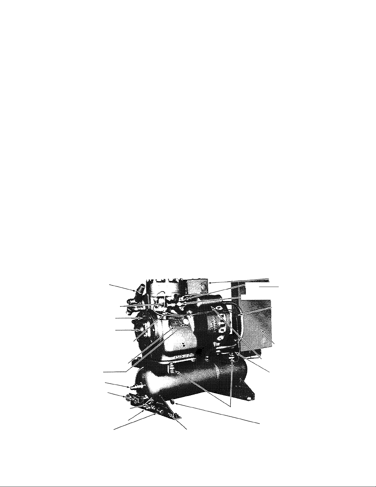
Fig. 1 - Typical 2 Cylinder Water-Cooled Condensing Unit
MOUNTING SPRINGS
(REMOVE BOLTS BEFORE STARTING)
CONDENSER NAMEPLATE
(07DA102, Single-Phase Illustrated)
TERMINAL BLOCK
discharge‘shut-off valve
DISCHARGE GAGE CONNECTION
RUN CAPACITOR
CONTROL BOX
DISCHARGE MUFFLER
CONDENSING UNIT
NAMEPLATE (USE
FOR WARRANTY
PURPOSES)
LIQUID LEVEL TEST
COCK
Page 3
Carrier
INSTALLATION 06D,07D
DISCHARGE
GAGE CONN.
SUCTION
PRESSURESTAT CONNECTION
SUCTION SHUT-OFF
VALVE
SUCTION GAGE
CONN.
PUMP END BEARING
HEAD
OIL PUMP COVER
BULL'S EYE
OIL DRAIN PLUG
WATER OUTLET
(COOLING TOWER ONLY)
FUSIBLE UNION
WATER INLET
(COOLING TOWER)
WATER INLET
AND OUTLET
(CITY WATER)
'LIQUID LINE CONN.
. DISCHARGE MANIFOLD
-WATER
REGULATING VALVE
PRESSURE CONN
DISCHARGE MUFFLER
TERMINAL BLOCK
COMPRESSOR NAMEPLATE
RUN
CAPACITORS
START
CAPACITORS
CONTROL BOX
CONDENSING UNIT
NAMEPLATE (USE
FOR WARRANTY
PURPOSES)
REFRIGERANT TAG
MOUNTING
SPRINGS (REMOVE
BOLTS BEFORE STARTING)
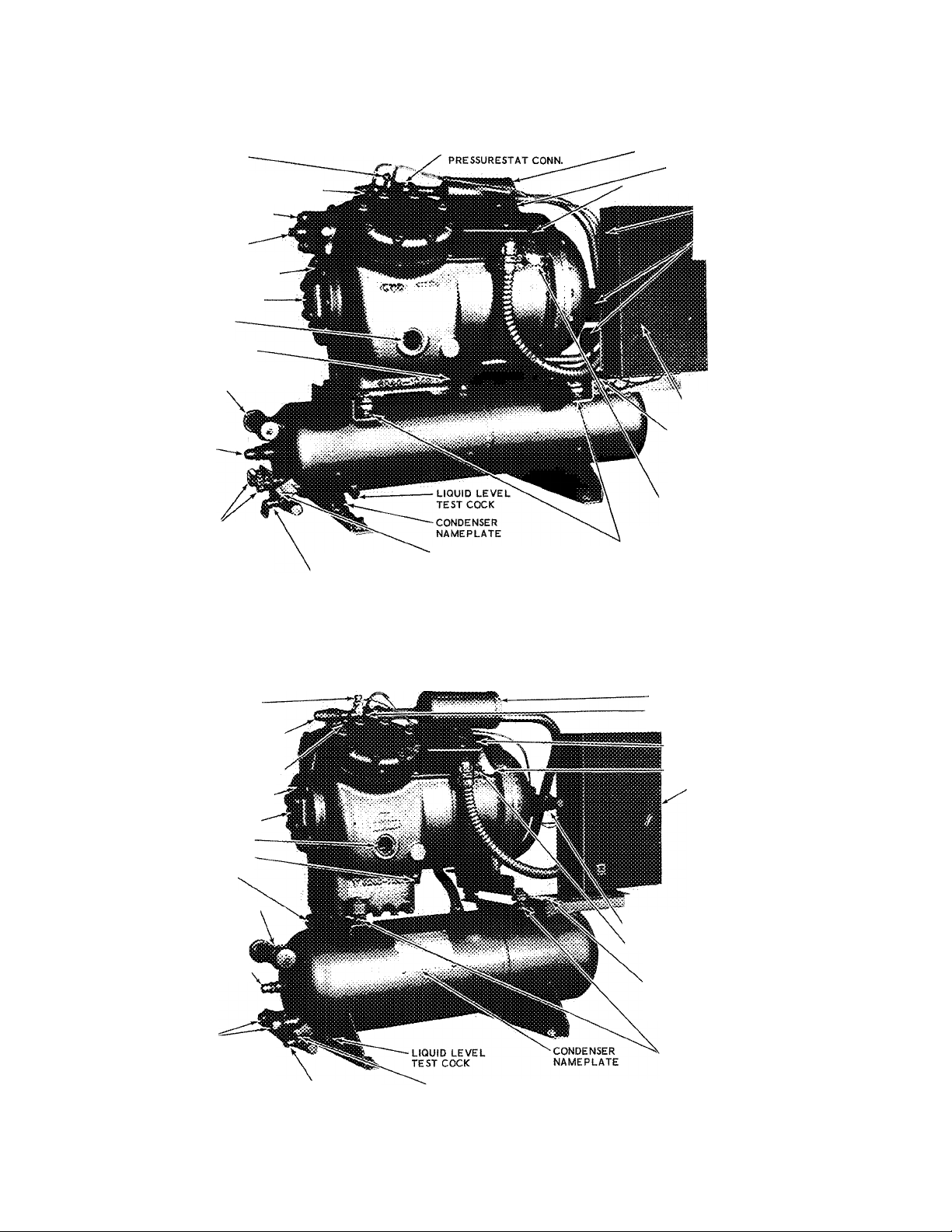
Fig. 2 - Typical 4 Cylinder Water-Cooled Condensing Unit
DISCHARGE GAGE
CONN.
DISCHARGE SHUT-OFF
VALVE
SUCTION MANIFOLD
PRESSURESTAT CONN,
PUMP END BEARING
HEAD
OIL PUMP COVER
BULL’S EYE
OIL DRAIN PLUG
PURGE COCK
WATER OUTLET
(COOLING TOWER
ONLY)
FUSIBLE UNION
WATER INLET
(COOLING TOWER)
WATER INLET AND
OUTLET (CITY
WATER
(07DA103, Single-Phase Illustrated)
'LIQUID LINE
CONN.
■WATER REGULATING
VALVE PRESSURE CONN.
DISCHARGE MUFFLER
DISCHARGE MANIFOLD
PRESSURESTAT CONN.
-TERMINAL BLOCK
REFRIGERANT TAG
CONTROL BOX
SUCTION SHUT-OFF VALVE
COMPRESSOR NAMEPLATE
CONDENSING UNIT
NAMEPLATE (USE FOR
WARRANTY PURPOSES)
MOUNTING
SPRINGS
(REMOVE BOLTS
BEFORE STARTING)
Fig. 3 - Typical 4 Cylinder Water-Cooled Condensing Unit
(07DA106, Three-Phase Illustrated)
Page 4
06D,07D INSTALLATION
DISCHARGE GAGE
CONN.
DISCHARGE SHUT-OFF
VALVE
DISCHARGE MANIFOLD
PRESSURESTAT CONN.
PUMP END BEARING
HEAD
OIL PUMP COVER
BULL'S EYE
WATER INLET AND
OUTLET HEADERS
(SEE FIG 18 FOR
PROPER CONNECTIONS)
MOUNTING SPRINGS
(REMOVE BOLTS BEFORE
STARTING)
LIQUID LEVEL
TEST COCK
DISCHARGE MUFFLER
SUCTION MANIFOLD
PRESSURESTAT CONN
TERMINAL BLOCK
SUCTION SHUT-OFF
VALVE
CONTROL BOX
REFRIGERANT
TAG
COMPRESSOR
NAMEPLATE
CONDENSING UNIT
NAMEPLATE
OIL FILL PLUG
LIQUID LINE CONN.
' WATER REGULATING VALVE
PRESSURE CONN
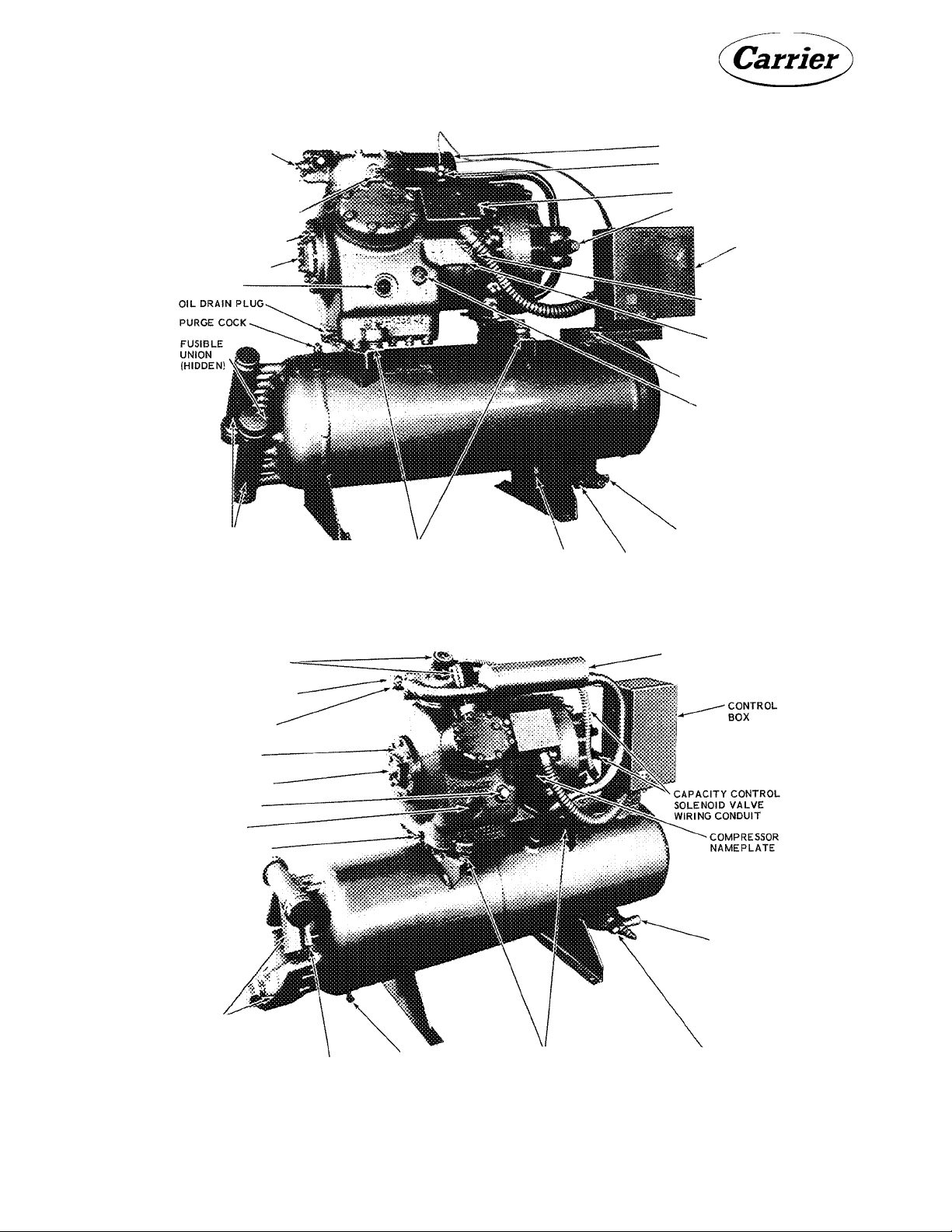
Fig. 4 - Typical 6 Cylinder Water-Cooled Condensing Unit
CAPACITY CONTROL
SOLENOID VALVES
DISCHARGE SHUT-OFF
VALVE
DISCHARGE GAGE
CONNECTION
PUMP END
BEARING HEAD
OIL PUMP COVER
OIL FILL PLUG
BULL'S EYE
OIL DRAIN PLUG
WATER INLET
AND OUTLET
HEADERS (SEE
FIG. 18 FOR
PROPER
CONNECTIONS)
(07DA210, Three-Phase Illustrated)
FUSIBLE
UNION (HIDDEN)
' LIQUID
LEVEL TEST
COCK
MOUNTING SPRINGS
(REMOVE BOLTS BEFORE
STARTING)
DISCHARGE MUFFLER
LIQUID LINE
CONNECTION
WATER REGULATING VALVE
PRESSURE CONN
Fig. 5 - Typical 6 Cylinder Water-Cooled Condensing Unit - Capacity Control
(07DA215, Three-Phase Illustrated)
Page 5
NOTES
1. NET WEIGHT INCLUDES OIL BUT NOT REFRIG. CHARGE.
2. OIL PUMP IS AUTOMATICALLY REVERSIBLE FOR
EITHER DIRECTION OF ROTATION
3. CONTROL BOX DRAWING 06D-20I-EI
4. MUFFLER DRAWING ' 06D- 202-4
LIQUID STRAINER-DRIER
CRANKCASE HEATER PKG.
YES NO
UNIT
MODEL
07DAI02
07DA203
NET WEIGHT
(LBS)
181
190
A D E
2'-s|'
4''
2-7 C
if
3 i
z
(/)
>
>
5
z
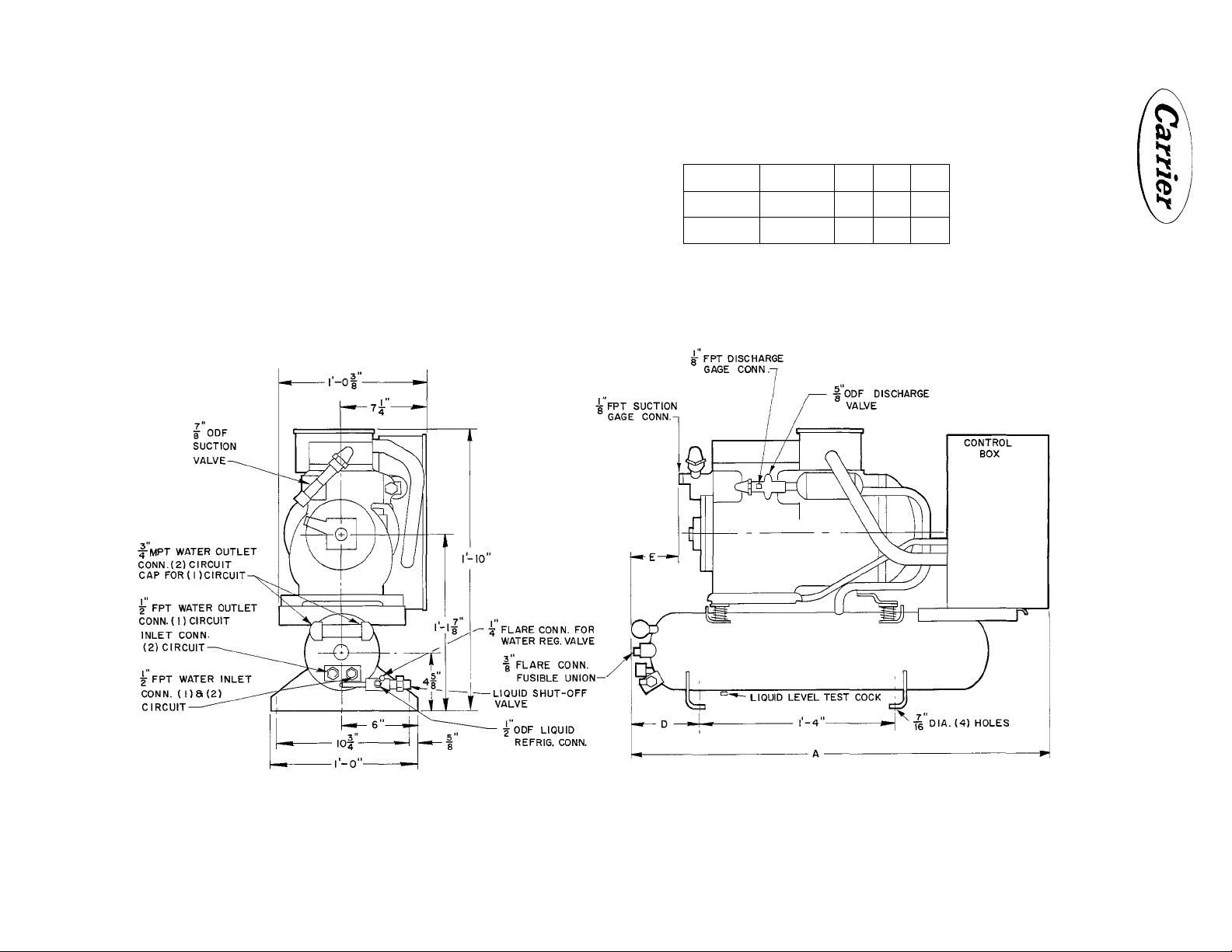
Dimensions are approximate. Certified dimension drawings are available on request.
Fig. 6 - Dimensions for 07DA102 and 07DA203
Page 6
NOTES'
1. NET WEIGHT INCLUDES OIL BUT NOT REFRIG. CHARGE.
2. OIL PUMP IS AUTOMATICALLY REVERSIBLE FOR
EITHER DIRECTION OF ROTATION.
3. CONTROL BOX drawing: 06D-20I-EI
4. MUFFLER DRAWING • 06D- 202-4
LIQUID STRAINER-DRIER
CRANKCASE HEATER PKG.
YES NO
UNIT
MODEL
t
---------------------
07DAI03 247 2-9"
07DAI06 2 94
07DA208
NET WEIGHT
(LBS)
330
2'-9|"
3'-3|"
A
I'-iiir"
2-4 J,
c 0 E
l'-4"
.1 ...n
I-IO
6"
7"
F G H
5"
I'-O"
8
|J-''
I'-l"
' 8
4|"
5®"
^4
J K L
6"
s'"
bg
5 "
8
7”
8
M
I-2-L"
r 7"
w
MPTXFPT
3 "
4
1 "
1"
3"
4
>
>
5
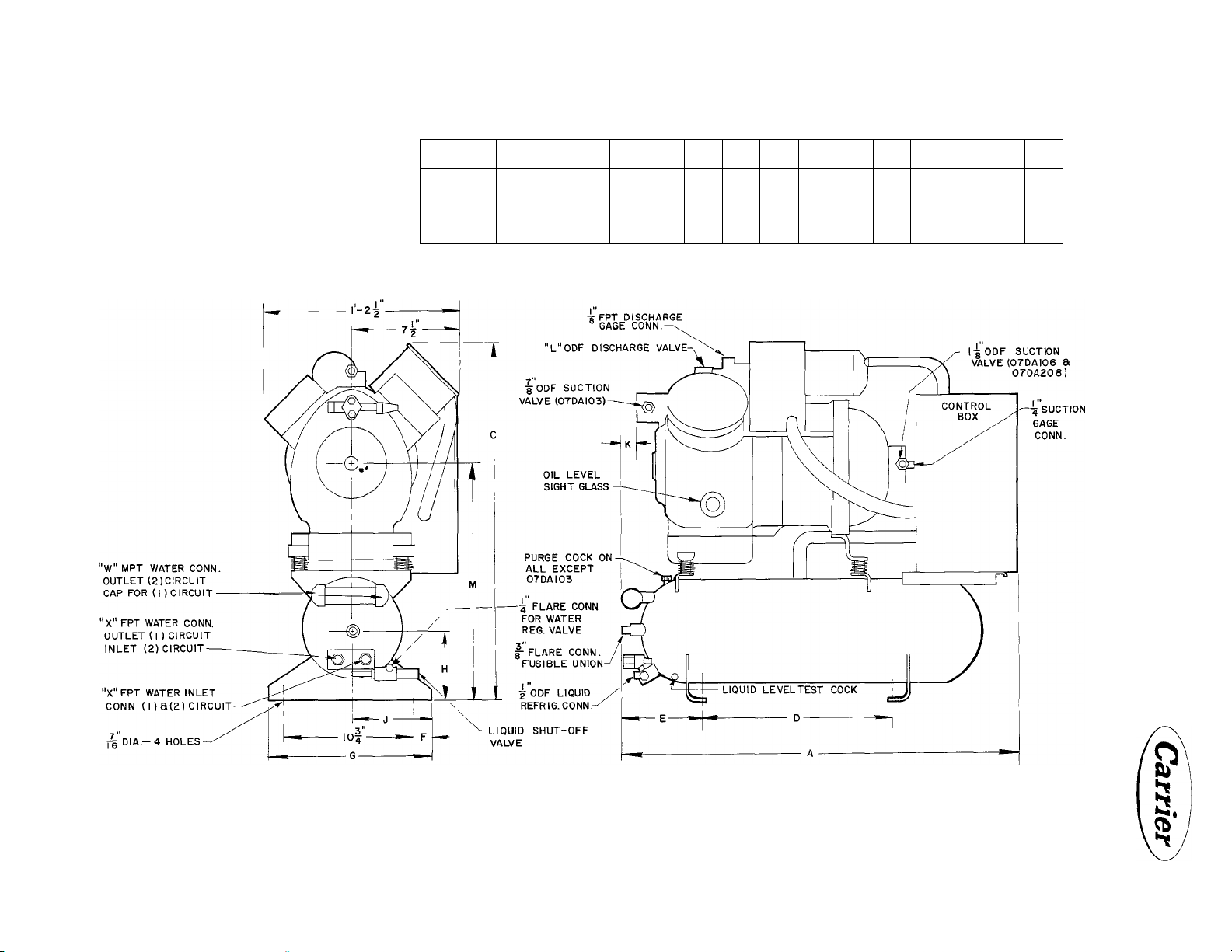
Dimensions are approximate. Certified dimension drawings are available on request.
Fig. 7 - Dimensions for 07DA103,106 and 208
Page 7
#
NOTES
1. NET WEIGHT INCLUDES OIL BUT NOT REFRIG. CHARGE.
2. OIL PUMP IS AUTOMATICALLY REVERSIBLE FOR
EITHER DIRECTION OF ROTATION.
3. CONTROL BOX DRAWING 06D-20I-EI
4. MUFFLER DRAWING 06D-202-4
PRESS. ACTUATED CONTROL VALVE(S)
LIQUID STRAINER- DRIER
CRANKCASE HEATER PKG.
YES NO
UNIT
MODEL
07DA2I0 WITHOUT
07DB2I0
CAPACITY
CONTROL
WITH
NET WEIGHT
(LBS)
475
z
>
>
5
z
Dimensions are approximate. Certified dimension drawings are available on request.
Fig. 8 - Dimensions for 07DA210 and 07DB210
Page 8
NOTES.
1. NET WEIGHT INCLUDES OIL BUT NOT REFRIG. CHARGE.
2. OIL PUMP IS AUTOMATICALLY REVERSIBLE FOR
EITHER DIRECTION OF ROTATION.
3. CONTROL BOX DRAWING OSD- 201-El
4. MUFFLER DRAWING OSD- 202-4
PRESS. ACTUATED CONTROL VALVEiS)
LIQUID STRAINER-DRIEF
CRANKCASE HEATER PKG.
YES_ NO
UNIT
MODEL
07DAII2
07DA2I5
07DBI 12
07DB2I5
CAPACITY
CONTROL
WITHOUT
WITH 590
NET WEIGHT
(LBS)
580
z
>
>
o
Dimensions are approximate. Certified dimension drawings are available on request.
Fig. 9 - Dimensions for 07DA,DB112 and 07DA,DB215
Page 9
NOTES.
1. NET WEIGHT INCLUDES OIL BUT NOT REFRIG. CHARGE.
2. OIL PUMP IS AUTOMATICALLY REVERSIBLE FOR
EITHER DIRECTION OF ROTATION.
3. CONTROL BOX DRAWING 06D-201-El
4. MUFFLER DRAWING 06D-202-4
CONTROL BOX r
MOUNTING SPRINGS
MUFFLER
CRANKCASE HEATERS
YES NO
MODEL
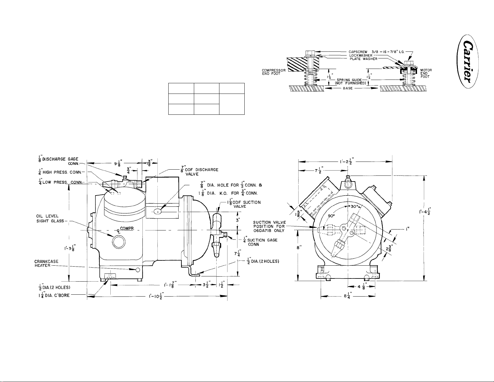
06DA7I8 210 LBS.
06DA8I8
NET
WEIGHT
225 LBS.
OIL
CHARGE
7 PINTS
#
SPRING MOUNTING ARRANGEMENT
(TYPICAL)
z
(/>
>
>
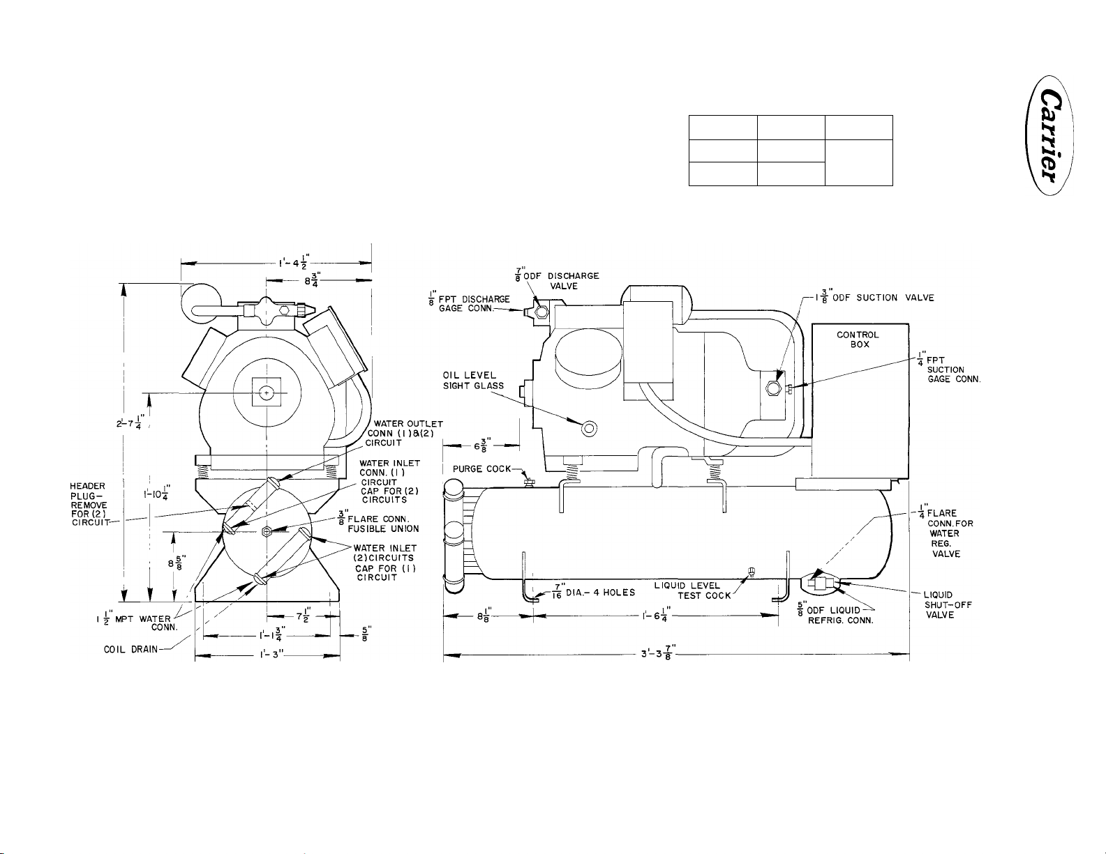
Dimensions are approximate. Certified dimension drawings are availabie on request.
Fig. 10 - Dimensions for 06DA718 and 06DA818
5
z
Page 10
NOTES
I NET WEIGHT INCLUDES OIL BUT NOT REFRIG. CHARGE.
2. OIL PUMP IS AUTOMATICALLY REVERSIBLE FOR
EITHER DIRECTION OF ROTATION.
3. CONTROL BOX DRAWING 06D-20I-EI
4. MUFFLER DRAWING 06D-202-4
PRESS. ACTUATED
CONTROL VALVE(S)
CONTROL BOX
MOUNTING SPRINGS
MUFFLER
CRANKCASE HEATER
YES NO
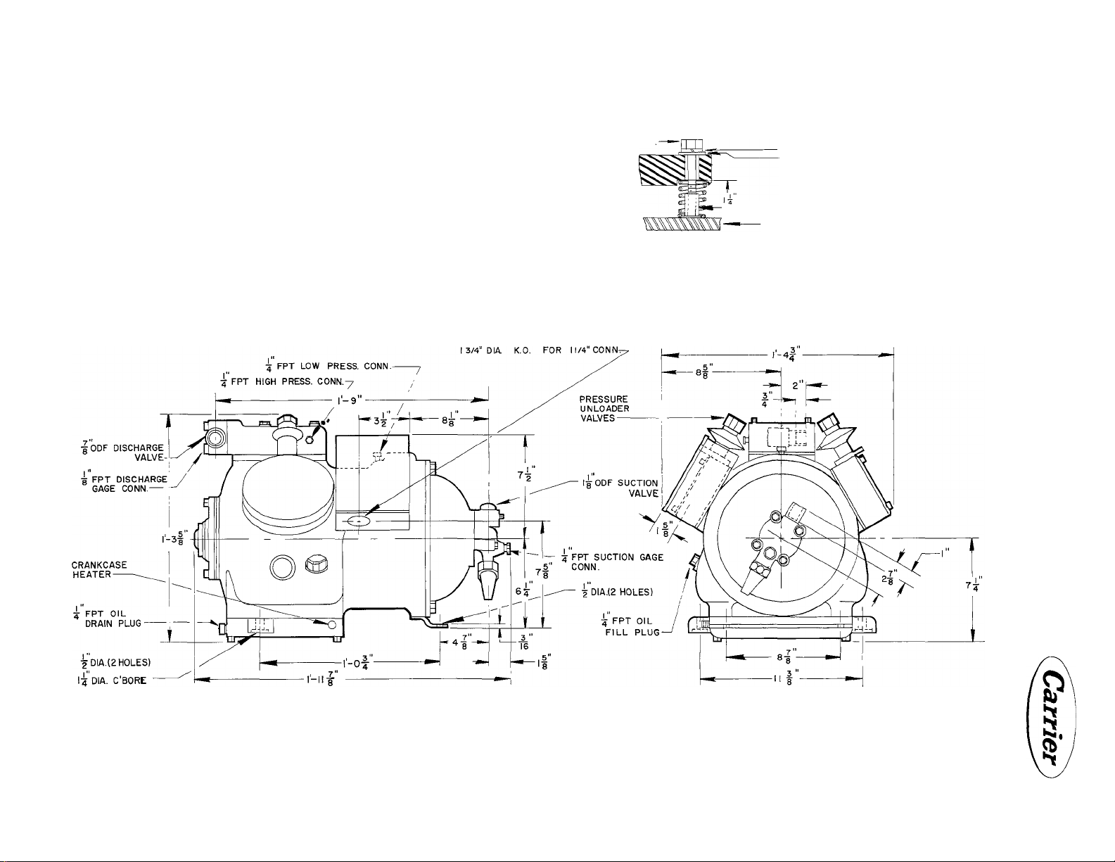
NET WEIGHT 270 LBS.
OIL CHARGE 10 PTS.
06DA DENOTES NO UNLOADERS
06DE DENOTES 2 STEP PRESSURE
ACTUATED UNLOADING
M/8" DIA. HOLE FOR 3/4“C0NN..
13/8“ DIA. K.O. FOR I" CONN. 8.
3Æ-I6 X 1 1/2 LG
CAPSCREW
COMPRESSOR
END FOOT
LOCKWASHER —
PLATE WASHER
SPRING GUIDE-
JL (NOT FURNISHED)
SPRING MOUNTING ARRANGEMENT
BASE-
(TYPICAL)
3/8 - 16-7/8‘‘LG. CAPSCREW
ai
MOTOR
END
FOOT
z
>
>
5
z
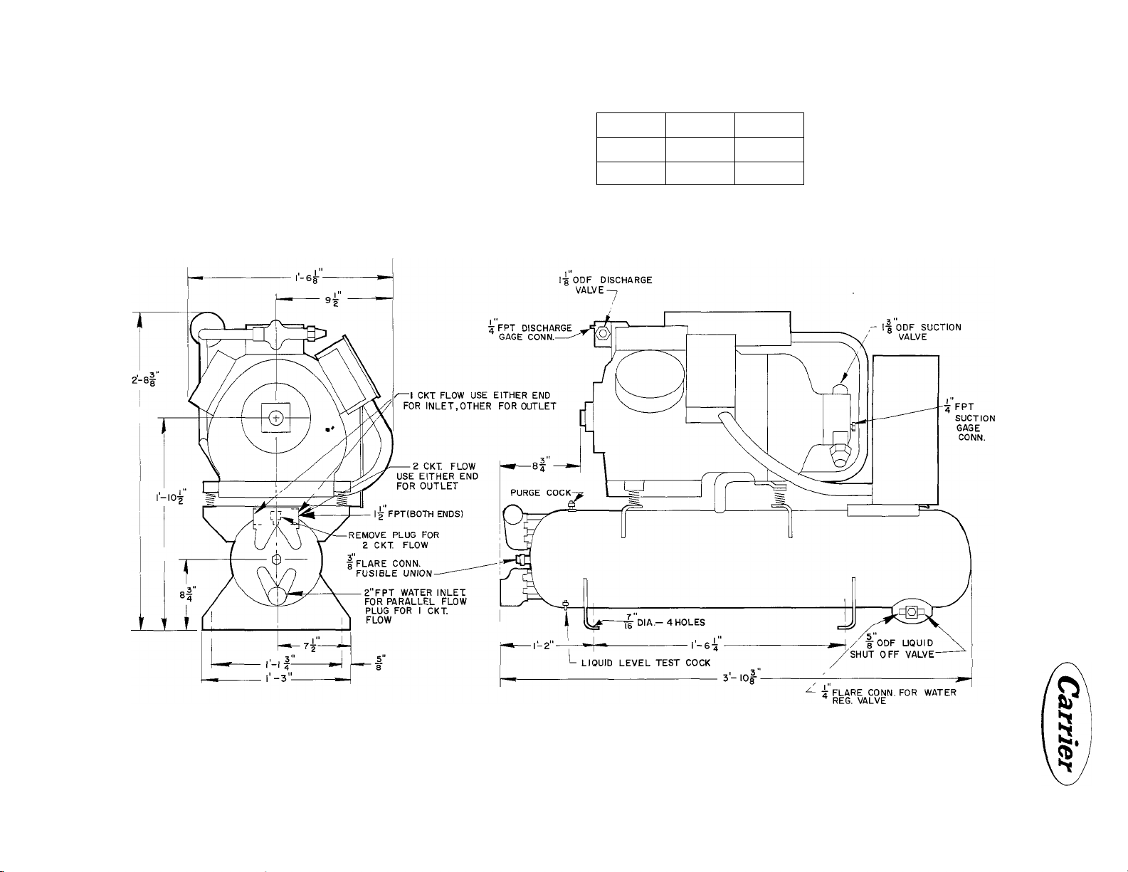
Dimensions are approximate. Certified dimension drawings are available on request.
Fig. 11 - Dimensions for 06DA824 and 06DE824
Page 11

NOTES
1. NET WEIGHT INCLUDES OIL BUT NOT REFRIG. CHARGE.
2. OIL PUMP IS AUTOMATICALLY REVERSIBLE FOR
EITHER DIRECTION OF ROTATION.
3. CONTROL BOX DRAWING OSD-201-El
4. MUFFLER DRAWING OSD-202-4
PRESS. ACTUATED
CONTROL VALVE(S)
CONTROL BOX
MOUNTING SPRINGS
MUFFLER
CRANKCASE HEATER
YES
NO
MODE L
*
06D( )337
06 D( Ì537
„ 06DA DENOTES NO UNLOADERS
06DE DENOTES 2 STEP PRESSURE
NET
WEIGHT
285 LBS.
ACTUATED UNLOADING
OIL
CHARGE
10 PINTS
ELECTRICAL
208-3-60
230-3-60
230-3-50
400-3-50
460-3- 60
SPRING MOUNTING ARRANGEMENT
D
1 3/8" DIA. HOLE FOR 1" CONN, a
8"
1 3/4" DIA. K.O. FOR 1 1/4" CONN.
1 1/8" DIA. HOLE FOR 3-4" CONN.,
13/8" DIA K.O. FOR l" CONN. 8
9"
1 3/4" DIA K.O. FOR 1 1/4" CONN.
(TYPICAL)
"E" CONNECTION SIZES
z
>
>
5
Dimensions are approximate. Certified dimension drawings are available on request.
Fig. 12 - Dimensions for 06DA337,06DE337 and 06DA537,06DE537
Page 12

FIGURE I
n FIGURE H
MUFFLER
PKG.
NO.
6D44-
882
6047-
882
6075-
882
FIG.
NO.
I
JL 10
IL
1-4"
A
9|''
DIMENSIONS
B
c D
5"
-
8
7"
if
8
4"3"4 4"
DIXH.
COND.
CONN.
INLET
MTG.
HORIZ.
OR
VERT
CONN.
INLET
E
—
-
I'ODF
^OOM
|-§ODF
|0DF
l-gODF
r
3"
4
2
7"
8
MODELS
USED
ON
06DA7I8
06DA8I8
06D_824
060—337
060 — 537
z
Ui
>
>
5
z
Dimensions are approximate. Certified dimension drawings are available on request.
Fig. 13 - Dimensions for 06D Muffler Assembly
Page 13

Carrier
INSTALLATION 06D,07D
m
Table 1 - 07D Condensing Unit Data
Condensing Unit A102 A203 A103 A106
Compressor Mo lei
Unit Type
Nominal Tons
Evap Temp Le\ el
No. of Cy 1 inders
Bore ond Stroke (in )
Compr Speed (rpm)
DispI at 1750 Rpm (cfm)
Suet Gas Conn
Disch Gas Conn. (ODF) 5/8 5/8
Liq Line Conn
Refrigerant 12
Optg Ref Charge (lbs)** 2
Cond Storoge Cap
(80% Liquid at 100 F)
Water Conn Inlet 1/2 FPT
Cooling Tower
Water Conn
City Water
Frangible Discs, M. Fl. 3/8
06DA109
H,M,L
2 X 1-3/8 2 X 1-1/4
1750
(ODF)
(ODF)
Outlet
Outlet 1/2 FPT 1/2 FPT 1/2 FPT
Inlet
1/2 FPT
1/2 FPT
06DA808
WC
2
H,M
2 2
1750 1750
8.69 7 96 13.1
7/8 7/8 7/8 1-1/8 1-1/8 1-1/8 1-3/8 1-3/8
1/2
18 18.5 20.5 39.5 35.8 45
1/2 FPT(2) 1/2 FPT(2) 1/2 FPT(2) 1/2 FPT(2) 3/4 FPT (2)
3/4 MPT 3/4 MPT 1 MPT 1 MPT 1 MPT *1-1/2 MPT 2 FPT 2 FPT
1/2 FPT 1/2 FPT 1/2 FPT
WC
3
1/2 1/2 1/2
22
2.5
3/8
06DA013 06DA718
WC WC WC
3
H,M H
4 4 4
1-13/16 X 1-1/4 2 X 1-7/16 2 X 1-7/16 2 X 1-7/16
5/8 7/8 7/8
12 12 22 22 22
2.7 2.0 1.9
3/8 3/8 3/8
5 5
1750
18.3
1/2 FPT
-------------------------
06DA818
M
1750 1750 1750
18.3 18 3 23.88 37 07 37 07
1/2 1/2 5/8 5/8 5/8
1/2 FPT
1/2 FPT 3/4 FPT 1-1/2 MPT 1-1/2 FPT 1-1/2 FPT
3/4 FPT 1-1/2 MPT 1-1/2 FPT
1
A .
A208
WC
7-1/2
H,M
4
7/8 7/8 1-1/8
2 7 3.2 4.3 4.3
3/8
210
B
06DA724 06DA337 06DA537
WC
10 10
H,M H,M
6 6 6
2 X 1-1/4 2 X 1-15/16
67
1-1/2 MPT
3/8
A
WC WC
2 X 1-15/16
1750
12 22
88 88
*1-1/2 FPT(2) *1-1/2 FPT(2)
1-1/2 FPT
3/8 3/8
'^215
B
15
H,M
1750
1-3/8
1-1/8
*Remove upper header plug for parallel circuiting for cooling tower application (See Fig. 18 )
**Condensing unit minimum operating refrigerant charge
WC — Water-Cooled
INSPECT THE SITE
Preliminary Survey
Before starting the installation, make a survey
to determine the following:
SPACE REQUIREMENTS
Dimensions for the 07D Condensing Units are
given in Table 2. Allow additional room to re
move the compressor heads and valve plates.
Place the unit so the suction and discharge shut
off valves can be easily reached and the oil
level checked.
Install the unit where it will be warmer than the
refrigerated space, to prevent refrigerant from
condensing in the compressor crankcase during
shutdown. Water-cooled condensing units must
be protected against freezing. Make provision
in the piping layout to drain and blow out the
condenser and water piping if the system is to
be shut down in winter.
Table 2 - Condensing Unit Dimensions
Length
Unit
07DÂ102 WC 0 0)
07DA102 WC (Poly 0)
07DA203 WC 0 </.)
(in.)
21-3/8 12 ■ 21-1/2
29-1/16 12 21-1/2
29-1/2
07DA203 WC (Poly 0) 31-3/16
07DA103 WC (1 </.)
07DA103 WC (Poly0)
07DA106 WC (All)
07DA208 WC (All)
07DA210 WC (All)
07DA112 WC (All)
31-3/32 14 22-5/8
32-3/4
33-1/4
39-5/8
39-11/16
46-3/8 17-7/16
07DA215 WC (All) 46-3/8
NOTE: WC - Water-Cooled
Width
(in.)
15-1/2
17-7/16
Height
(in.)
12
12
21-7/16
21-7/16
14 22-5/8
14 27-7/8
14 27-7/8
31-7/32
32-3/4
32-3/4
13
Page 14

06D,07D INSTALLATION
Table 3 - Electrical Data for 06D Compressor Units and
07D Water-Cooled Condensing Units
Carrier
06D 07D
Compressor Condensing
Unit
A808
A718
A818
¿824
*337
¿537
Unit
A102 208/3/60 7.9
A203 208/3/60
A103 208/3/60
A106 208/3/60 19.3
A208 208/3/60 35.0
*210
¿112
¿215
Full
Volt/Phase Load
Cycle (amps)
230/1/60 11.2
230/3/60
460/3/60 3.5
230/3/50 5.8
400/3/50 3.5
230/1/60 15.8
230/3/60
460/3/60 5.2
230/3/50
400/3/50
230/1/60
230/3/60
460/3/60
230/3/50 8.9
400/3/50 5.3
230/1/60 25.0 100.0 35.0
230/3/60 16.8
460/3/60 8.5
230/3/50
400/3/50 8.5
230/3/60
460/3/60
230/3/50 26.2
400/3/50 15.8
208/3/60 36.0
230/3/60
460/3/60 15.8
230/3/50
400/3/50
208/3/60 44.0
230/3/60 39.7
460/3/60 19.9
230/3/50
400/3/50 19.9
208/3/60
230/3/60 44.3
460/3/60 22.2
230/3/50
400/3/50 22.2
208/3/60 55.7
230/3/60 50.0
460/3/60 25.0
230/3/50 41.5
400/3/50 25.0
Locked
Rotor
(amps)
6.8
11.8
10.3
8.6
5.2
12.2
16.1 70.0 22.5 25.0
10.6
5.3 28.8 7.4 9.0
14.0
31.5
15.8
31.5
26.2
15.8
33.0
49.3 191.0 69.0 80.0 15.9 4
37.2 143.0 52.0 60.0 13.2
137.0 48.8 60.0 10.8
124.0
103.0
137.0 48.8 60.0
124.0
103.0 36.7 40.0
170.0 61.5 70.0 14.1
153.0
128.0 46.2 50.0
172.0 62.0 70.0
266.0
240.0
120.0
200.0
115.0
Overload Fusetron
(amps) (amps)
48.5
50.0
43.0 9.5 12.0 2.8
22.5 4.8
35.8
21.5 4.8
63.5
70.0
57.5 14.4
28.8
47.8
27.5 7.2 9.0 3.17
63.5 17.0 20.0 4.1
57.5 14.8 17.5 4.1
47.7 12.4 15.0 3.42
27.5 7.4 9.0 3.42
95.0 27.0 30.0 6.6
86.0 23.5 30.0 6.6
43.0
72.0 19.5 25.0 5.5
41.0
62.0
59.0 22.0 25.0 9.0
62.0
59.0 22.0 25.0 9.0
77.0 27.8 35.0 14.1
74.0 •
86.0
83.0
Trip Size
11.0 12.0 2.8
15.6 17.5
8.0 10.0 2.35
16.5 20.0 3.8
22.0 25.0 3.8
7.2
12.0
11.8 15.0
11.8 15.0 5.5
44.0
22.0
36.7 40.0 9.0
44.0
22.0
55.5 70.0 14.1
27,8
31.0
31.0
78.0 90.0 18.9
70.0
35.0 40.0 18.9
58.0
35.0
5.6
5.6
17.5 3.8 14 41
9.0 3.8
15.0 3.17
40.0 6.6
50.0 10.8 8
25.0
50.0
25.0
35.0
35.0
35.0 13.2
80.0
70.0
40.0
Max
Kw
2.8
2.8
2.35
4.1
4.1
6.6 14 100
10.8
10.8
10.8
10.8
9.0
11.7
11,7
15.9
15.9
18.9
15.7
15.7
Min
Branch
Circuit Wire Length Old
Size (AWG)
14
14
14 63
14 249
14
14 216
14 32
12 34
14
14
14 143
14 31
12 33
14 35
14 161
14
14 140
10 50
10 32
10 63
12 48
14 87
6
12
8 64
12 74
6
8 53
12
8 64
12 75
6
6
10 107
6 76
10 85
6 57
10
6 67
10
4
4
8 131
6
8
Max Wire
(ft)*
Reference
Number
49
29
74
164
50
36
63
53
85
63 6D67
85
41
63
69
96
83
61
75
60
115
6D21
6D28
6D40
6D47
6D48
6D68
6D73
6D75
*Wlre sizes are based on minimum wire size needed to
comply with Notional Electric Code for TW Type Wire.
Maximum wire length is based on a 1% voltage drop in the
branch circuit. Where up to 3% voltage drop is acceptable,
maximum wire lengths can be multiplied by 3.
14
Page 15

INSTALLATION 06D,07D
m
m
VENTILATION OF MACHINE SPACE
Ventilation must be provided to remove heat
from the compressor and allow refrigerant gas
to escape in case of a leak.
VIBRATION ISOLATION
Install the unit where the floor is strong enough
to support it. It is not necessary to install it on
a special foundation because vibration is ab
sorbed by the compressor mounting springs.
On critical installations it may be desirable to
enclose the unit in an equipment room to pre
vent direct transmission of sound to occupied
spaces. Place the unit where it will not be dam
aged by traffic or flooding. It may be necessary
to cage the unit.
NOTE: Remove the compressor hold
down bolts to allow the compressor to
float freely on the springs.
INSPECT SHIPMENT FOR LOSS AND DAMAGE
Check the shipping list immediately to see if
the shipment is complete. Inspect the unit for
damage. File a claim with the shipping company
immediately if damaged or lost.
Do not remove the tags until they are read and
understood. Save tags, instructions, installation
record card and shipping receipt. The person
starting machine may need them for reference.
CODE COMPLIANCE
Install these units in accordance with applicable
codes and ordinances. Refer to ASA-B9 1-1953,
American Standards Association's "Mechanical
Refrigeration Safety Code."
Frangible discs are provided to protect against
explosion in cases of extreme heat from an
external source.
Before installing the unit, check the electric
service to insure that it is adequate. The volt
age at the motor terminals must not vary more
than plus or minus 10% of the nameplate volt
age during start-up or while running.
Phase unbalance for three-phase units must not
exceed 2%. Where unbalance exists, connect the
two lines with the higher amperages thru the
switch heater elements.
Table 3 lists the minimum wire sizes for 6D
Water-Cooled Condensing Units.
Figure 14 - 16 are the unit wiring diagrams for
the water-cooled condensing units.
Water-Cooled Condensing Unit Control
T ransformers
ELECTRICAL REQUIREMENTS
SET THE UNIT IN PLACE
Set the unit in place. Level the condenser and
bolt the unit to the floor. For dimensions be
tween hold-down bolt holes, see Fig. 6 - 13.
Control transformers are not furnished with
the 440 condensing units. Recommended trans
former sizes are shown in Fig. 16. All 460/3/60
units have 115-volt control circuits. All other
units have 230-volt control circuits.
15
Page 16

06D,07D INSTALLATION
POWER AND CONTROL CIRCUIT SCHEMATIC
□ -TEKMINAL tLOCK CONNECTION
C - CONTACTOR
CR-CONTROL RELAY
r-FU8E
IT-INTERNAL MOTOR THERMOSTAT
HP-HI PRESSURESTAT
LP-LO PRESSURESTAT
HR-H0L0IN6 RELAY
OL-OVERLOAO (OVERCURRENT RELAY)
PO-PUMP OUT RELAY
TM’TIMER MOTOR
-----
FACTORY WIRINO
'•"FIELD WIRINO
I. CONTROL MUST BE FIELD SUPPLIED. j
MINIMUM CONTACT RATING MUST BE 25VA.
t. LIQUID LINE SOLENOID VALVE MUST BE
FIELD SUPPLIED. MAXIMUM LOAD'.
«OVA HOLDINOi 200 VA INRUSH.
S A60V AND 57SV UNITS HAVE A II5V
CONTROL CIRCUIT WHICH MUST BE
ENERGIZED AT LI AND L2 FROM AN
EXTERNAL SOURCE 400V UNITS HAVE
A 2SO V CONTROL CIRCUIT WHICH MUST
BE ENERGIZED AT LI AND L2 FROM
AN EXTERNAL SOURCE. ALL OTHER
UNITS HAVE A 2SOV CONTROL CIRCUIT
WHICH IS ENERGIZED THRU FACTORY
WIRING AT LI AND L2
4. A TRANSFORMER OF THE FOLLOWING
RATING MUST BE FIELD SUPPLIED FOR
400V, 4S0V AND B7SV UNITS*.
ALL 0TD()|I2, 070U2I5, OSDOSST,
0GD0S37 AND 060()S24 UNITS; ISO VA.
ALL OTHER units; 100 VA.
B.OPEN FUSED DISCONNECT SWITCH, ONLY
FOR SERVICING EQUIPMENT. DISCONNECT
MUST REMAIN CLOSED IN ORDER FOR
THE CRANKCASE HEATER TO OPERATE.
S.290V CONTROL CIRCUIT USES I/4 X
I '/4 SAMP FUSES.
IIS V CONTROL CIRCUIT USES 1/4 X
1^/4 10 AMP FUSES,
LEaCND
NOTES
Fig, 14 - Wiring Label 07D Condensing Units, 06D Compressor Units (3-Phase)
16
Page 17

INSTALLATION 06D,07D
(irc NOT! t)
#
I JUNCTION iOX
COMPREttOR
POWER AND CONTROL CIRCUIT SCHEMATIC
□ -TERMINAL BLOCK CONNECTION
C - CONTACTOR
CR-CONTROL RELAY
F-FUSE
IT-INTERNAL MOTOR THERMOSTAT
HP-HI PRESSURESTAT
LP-LO PRESSURESTAT
HR-HOLDING RELAY
OL-OVERLOAD (OVERCURRENT RELAY)
PO-PUMP OUT RELAY
TM-TIMER MOTOR
-----
FACTORY WIRING
-----
FIELD WIRING
RC-RUN CAPACITOR
SC-START CAPACITOR
SR-8TARTIN0 RELAY
1. CONTROL MUST BE FIELD SUPPLIED.
MINIMUM CONTACT RATING MUST BE 25VA.
a. LIQUID LINE SOLENOID VALVE MUST BE
FIELD SUPPLIED. MAXIMUM LOAD!
• OVA HOLDING^ 200 VA INRUSH.
•«OPEN FUSED DISCONNECT SWITCH, ONLY
FOR SERVICING EQUIPMENT. DISCONNECT
MUST REMAIN CLOSED IN ORDER FOR
THE CRANKCASE HEATER TO OPERATE.
0 CONTROL CIRCUIT IS 230V AND USES
*/4 X I '/4, S AMP FUSES
LEGEND
NOTES
CRANKCASE
HEATER
-AA/VW
i O-
• Al
V
Sl^
“tÍmer”
-0
VIEW
070ASOOOS3
Fig. 15 - Wiring Label 07D and 06D Units (1-Phase)
17
Page 18

06D,07D INSTALLATION
POWER WIRING
SINGLE PHASE
LI
FACTOR> WIRING IS IN ACCORDANCE WITH THE NATIONAL ELECTRICAL
CODE ANY FIELD MODIFICATIONS OR ADDITIONS MUST BE IN
COMPLIANCE WITH ALL APPLICABLE CODES
A6C VOLT UNITS HAVE 115 VOLT CONTROL CIRCUIT ENERGIZED
FROM EXTERNAL SOURCE AOO VOLT UNITS HAVE 250 VOLT
CONTROL CIRCUIT ENERGIZED FROM EXTERNAL SOURCE ALL
OTHER UNITS HAVE 230 VOLT CONTROL CIRCUIT ENERGIZED
THRU FACTORY WIRING AT L» AND L2
CONTROL CIRCUIT POWER REQUIREMENTS! ALL 07D( ) 112 8215 8
06D( )337,5378824 WITH 400V 8 460V DRAW 150 VA ALL
OTHER UNITS REQUIRE lOOVA WHEN CONTROL TRANSFORMERS ARE
REQUIRED THEY SHOULD BE SIZED ACCORDINGLY THESE RATINGS
APPLY TO DEVICES SHOWN ON CONTROL DIAGRAM, IF ADDITIONAL
ARE USED. TRANSFORMER SIZE MUST BE INCREASED PROPORTIONATELY
CONTROL CIRCUIT FUSES ARE 11/4" X 1/4" DIA CERAMIC TUBE RATED
AT -5 AMPS FOR 208 8 230V0LTS AND lOAMPS FOR 115 VOLTS
DO NOT SUBSTITUTE OVERLOAD RELAYS OF A HIGHER RATING THAN
ORIGINALLY SUPPLIED.
IF A CONTROL VOLTAGE POWER SUPPLY HAVING A GROUNDED SUPPLY
LEG IS USED, THE GROUNDED CONDUCTOR MUST BE CONNECTED TO
TERMINAL 3 AND F2 BYPASSED.
OPEN DISCONNECT ONLY WHEN SERVICING EQUIPMENT CRANKCASE
HEATER MUST REMAIN ENERGIZED WHEN EQUIPMENT IS SHUT DOWN
WIRING SHOWN IS FOR WATER-COOLED CONDENSING UNITS WITH
CONTROL BOX MOUNTED. COMPRESSOR UNITS ARE SHIPPED WITH
CONTROL BOX SEPARATE AND PIELD MUST SUPPLY INTERCONNECTING
WIRING WHERE NECESSARY
WOrning-DlSCONNECT ALL CIRCUITS BEFORE SERVICING THIS
ONE OVERLOAD ON SINGLE PHASE. TWO ON THREE PHASE
TIMER MOTOR (TM) CAM ROTATES AT 1/5 RPM WHEN TM IS
ENERGIZED TO PROVIDE 15 SEC. TIMING WITH SWITCHES (N A-A2,
B-B2, POSITION AND AMIN. 45 SEC, IN A-AI. B-BI, POSITION.
COMPLETE TIME GUARD CONTROL PROVIDES 15 SEC ADVANCE START
FOR CONDENSER AUXlUARIES AND PREVENTS COMPRESSOR RESTARTING
IN LESS THAN 5 MIN AFTER STOPPING
EQUIPMENT
Fig. 16 - Field Wiring for 06D, 07D Units
LEGEND
HR HOLDING RELAY
CR CONTROL RELAY
► C COMPRESSOR
M3 EVAPORATOR FAN OR
CHILLED WATER PUMP
M4 COOLING TOWER PUMP.AIR
COOLED OR EVAPORATIVE
CONDENSER FAN
M5 COOLING TOWER FAN OR
EVAPORATIVE CONDENSER PUMP
OL OVERLOAD
SV LIQUID LINE SOLENOID VALVE
SR STARTING RELAY
US UNLOADER SOLENOID
POR PUMP OUT RELAY
TM TIMER MOTOR
TERMINALS
Q MAIN TERMINAL STRIP
^ COMPRESSOR
18
MODEL
NUMBERS
070A102
07DA203
07DA103
060A7I8 A.B.C.D.E.F
07DA106 A.B. C.D, E, F
06DA6t8 A. C.D, E.F
07DA208
06D( )824 A, C. D. E. F
07D( )2I0 A. C.D. E, F
06D( )337 A. C.D,E.F
07D( )l 12
06 Di )537 A, C.D, E.F
07D( )2I5 A. C,D.e,F
A = 208/3/60
B • 230/1/60
C • 230/3/60
STANDARD
ELECTRICAL‘S
C HARACTERISTICS
A.B.C.D.E.F
A.B.C. D, E.F
A.B.C.D, E.F
A. C.D. E.F
A. C.D.E.F
D« 460/3/60
E» 230/3/50
F- 400/3/50
Page 19

INSTALLATION 06D,07D
[33 SINGLE PUMP OUT CONTROL WITH CITY WATER
1 FI Pel
=* CONTROL '
T'STAT t ,
---------------
------------
MS
--------
(>
' дих
____________
AUX
.CONTACT SV t
dd
^Z]
-INSERT SAFETY INTERLOCK
HERE (WHEN USED)
Q^single pump out control with:
tSEE NOTE 3
I I COOLING TOWER I 1 EVAPORATIVE
□ COOLING TOWER FAN ^ ^roRATiVE
I 1 AIR COOLED CONDENSER CONDENSER
-------
PUMP
syt
o-p—4^
LOW PRESS '
CUTOUT
•^OPTIONAL t SEE NOTE3
NOTES:
1 REMOVE WIRE FROM C TO LOW PRESSURE CUTOUT
AND ADD NECESSARY AUXILIARY CONTACTS
2 REMOVE WIRE FROM FI TO Щ AND INSERT DESIRED
INTERLOCKS AND OL'S
3 FIELD SUPPLIED T'STAT MUST HAVE MIN. CONTACT RATING
OF 25VA FIELD SUPPLIED SV MAX LOAD 60VA HOLDING;
200 VA INRUSH.________________________________________________
CONDUIT TO COMPRESSOR TERMINAL BOX ARRANGEMENT
Г“ " ■
a и
---
1 Г“
1
MOTOR TERM BOX
i
3 PHASE - 6 CYLINDER
ilfyXP)’
¿2 -] T|
03 OL 4СЯ-------------------
•O i
T Tj
“^2 1 T,
05 OL 40
--------------------
i COMPRESSOR
TERMINAL BOX ‘
I I PUMP DOWN CONTROL WITH CITY WATER
(SEE NOTES NO I THRU 6 BELOW)
.CONTROL T'STAT +
CONTACT SY»
I I PUMP DOWN CONTROL WITH.
I I COOLING TOWER [~~3 EVAPORATIVE CONDENSER
I ~1 COOLING TOWER FAN | ~| EVAPORATIVE CONDENSER
I 1 AIR COOLED CONDENSER
PUMP
l''l
CONTACT ®V T
M5 P
--------
[T]
|з
_
¿ *o—яй^—4-i>—
»OPTIONAL T SEE NOTE 6
NOTES FOR PUMP DOWN CONTROL DIAGRAMS:
1 REMOVE LOW PRESSURE CUTOUT BETWEEN C 8 Al AND CONNECT C TO Al
WITH ANY DESIRED INTERLOCKS
2 WIRE LOW PRESSURE SWITCH BETWEEN TERMINALS fil a [F].
3 REMOVE CONNECTION BETWEEN a CR NORMALLY OPEN CONTACT
A DO NOT USE PUMP DOWN CONTROL METHODS FOR COMPRESSORS LJUIPPED
WITH CAPACITY CONTROL USE SINGLE PUMP OUT CONTROL.
5 INSERT SAFETY INTERLOCKS HERE IWHEN USED)
6 FIELD SUPPLIED T'STAT MUST HAVE MIN. CONTACT RATING OF 25VA FIELD
SUPPLIED SV MAX LOAD 60 VA HOLDING ; 200 VA INRUSH
I I ELECTRIC UNLOADER CONTROL FOR COMPRESSORS FIELD EQUIPPED
WITH ELECTRIC CYLINDER UNLOADERS (TWO SHOWN)
PRESSURESTATS OR THERMOSTATS NOT FACTORY FURNISHED
--
0-
----------
ч:(^Ръ—
-B
MOTOR TERM BOX
a Ш
a в
OÎ
_____J_____
03 OL
-----
3 PHASE-2 0 4 CYLINDER
SINGLE PHASE
~05-
OL
!C
1
__
O?
40r
10
____1
COMPRESSOR
TERMINAL BOX
COMPRESSOR
TERMINAL BOX
4
CYLINDER
UNITS
2
CYLINDER
UNITS
USED ON SINGLE
PHASE UNITS ONLY
APPROXIMATE COMPONENT LOCATION IN CONTROL BOX
SIDE VIEW
Fig. 16 - Field Wiring for 06D, 07D Units (Confd)
19
OCDCTCCl IBCCTAT .
—В ^
TERMINAL
STRIP
------
(I PHASE
ONLY)
I HOLDING
TM KR
Л
’'ш
FRONT VIEW WITH COVER
REMOVED
RELAY
^AIN Ì
TERMINA®
STRIP I
Page 20

06D,07D INSTALLATION
PIPING AND ACCESSORIES
Elimination of Pipe Vibration
The liquid and suction lines are usually of soft
copper tubing. To absorb vibration, loop or
sweep tbe liquid and suction lines near the unit.
Fasten the tubing to walls or supports, using
vibration isolation type bangers as shown in
Fig. 17. Keep uninsulated lines away from hot
water or steam lines. Follow the piping prac
tices in Carrier System Design Manual, Part 3.
minute period has elapsed. On normal starts,
the control will operate 15 seconds before start
ing the compressor.
The heart of the control is the cycle timer. The
cam on the cycle timer completes one revolu
tion in five minutes. Whenever the compressor
is stopped the timer motor will automatically
run until the cam lever is operated, which in
turn actuates the necessary switches. When this
sequence is completed, the cycle timer is pre
pared to start the unit.
Table 4 shows the normal operating sequence
of the timer circuit. This table can be helpful
in diagnosing electrical problems.
Operation of the control circuit is generally the
same on all voltage units. However, wiring se
quences for the individual controls may vary,
such as overloads and safety devices.
The following is a general description of the
operating sequence of the control circuit. Refer
to the schematic wiring diagrams as a guide.
The functions of this control accessory are:
Fig. 17 - Refrigerant Line Hangers
Time Guard Control Operation
CONTROL CIRCUIT
This unit is equipped with controls which pro
vide automatic reset overload protection, time
delay in starting, and controlled cycling under
any cycling condition. Following shutdown of
the compressor for any reason (i.e., opening,
of the thermostat, functioning of a protective
device, power failure), the control permits re
starting of the compressor only after a five
1. To limit restart cycling of the compressor,
under any circumstance, to a minimum of
five minute intervals after stopping.
2. To allow time to run during normal "off
periods, thus utilizing this time as part of
the five minute timing interval described
above in No. 1.
3. To provide a 15 second delay on each com
pressor start before the compressor motor
starter is energized; to allow auxiliaries such
as condenser pump, condenser fan, chilled
water pump, etc. to be in operation before
the compressor starts. This feature will pre
vent nuisance cutouts due to momentary ac
tion of the high pressure switch or chilled
water flow switch during start-up.
20
Page 21

INSTALLATION 06D,07D
Table 4 - Recyling Control Circuit Normal Operation Chart
Unit at Rest
Control
Timer Relay
Coil 230 DE EN
Contacts N.O.
Contacts N.C.
Cycle Timer
Motor
Cam Up
Contacts A—A2 230
Contacts A—A]
Contacts B—B2 230
Contacts B —B|
Compressor Line DE
Accessories
Legend: EN - Energized CL
CL — Contacts Closed OP
DE — De-energized
*Accessories will continue to run if high or low pressurestat shuts off compressor.
Voltage
230
230
230 DE
230 OP OP
230 OP OP
230
Ready to Start
OP
CL
CL
CL
DE
Thermostat Closes
Instantaneous thru
15 Seconds
CL
OP
EN
Up
CL
CL
DE
EN
Contacts Closed and in Service
Contacts Open
Thermostat or
Safety Device
Normal
Run
EN DE DE
CL
OP CL
DE
Do wn
OP
CL CL
OP OP CL
CL CL OP
EN
EN
Opens —Instant
Thru 4-3/4 Min
OP OP
EN
Down
OP
DE
DE* DE
Unit Ready
to Restart
CL
DE
Up
CL
OP
DE
1. starting Sequence (Assuming evaporator in
terlocks and all operating safety controls
frigerant pressure rises and low-pressure
switch closes.
are in closed position)
Time: 0 Min 0 Sec - Timer switch plunger
is up at beginning edge of cam node
and contacts are in positions A-A2
and B-B2, as shown.*
Control thermostat closes, energizing liq
uid line solenoid valve (SV) and pump-out
relay (FOR), FOR N.O. contacts close. Re-
Condenser auxiliaries, such as condenser
water pump, tower fan, etc., start and their
auxiliary starter contacts close. Timer re
lay (TR) is energized thru timer switch con
tacts A-A2, closing TR N.O. contacts and
opening TR N.C. contacts. Timer motor (TM)
is energized thru timer switch contacts B-B2
and starts running.
* This is the position always reached by the cam each time after the compressor has stopped
and the timer motor has completed its 4 min and 45 sec timing run.
Starting Sequence of Time Guard Control (Single Pump-Out Arrangement Shown)
21
Page 22

06D,07D INSTALLATION
Carrier
■ L|
EVAPORATOR
---
SAFETY
DEVICE
CONTACTS,N.C.
INTERLOCK
CONTACTS,N.O.
----
LOW
PRESS.
SWITCH
CONTROL
THERMOSTAT
---------
*^^-0
------
M" AUX
CONTACTS,N.OT
CONTACTS,N.O.
J/_
POR
CONTACTS,N.C.
TR
2. Operating Condition
Time: 0 Min 15 Sec
Timer switch plunger has dropped off the
cam node and the contacts have switched to
positions A-Ai and B-Bi. Timer motor stops
running since TR N.C. contacts are open.
Operating Condition of Time Guard Control (Single Pump-Out Arrangement Shown)
TR
CONTACTS, N.O.
4^—
---------
TIMER MOTOR CAM
1/5 RPM, 15 SEC CAM NODE
Timer relay (TR) remains energized thru
TR N.O. contacts, which are now closed.
Compressor motor starter is energized thru
timer switch contacts A-Ai and compressor
starts. Compressor continues to run unless
circuit is broken by action of control ther
mostat or safety devices.
CONO AUX
PUMPOUT RELAY
LIQ SOL VALVE
COND AUX
AUX CONTACTS,NO.
—#—
OFF
O
O-
a
TIMER RELAY
■Ö
COMPRESSOR
TIMER MOTOR
O
—Cj-O—<•
HIGH
PRESS..
SWITCH
CONTACTS, N.C.
3. Stopping Sequence
Time: Any time after 15 seconds
Timer switch plunger is still in position of
having just dropped off the cam node, since
timer motor has not been running, and switch
contacts are in position A-Ai and B-Bi.
Thermostat opens when cooling load is sat
isfied. Liquid solenoid valve (SV) is de
energized and closes. Pumpout relay (POR)
is de-energized, and its contacts open. The
timer relay (TR) and compressor continue
to operate thru compressor starter auxiliary
contacts ”M" until system pumps down and
low-pressure switch opens. Then compres-
Stopping Sequence of Time Guard Control (Single Pump-Out Arrangement Shown)
TIMER MOTOR CAM
1/5 RPM, 15 SEC CAM NODE
sor and condenser auxiliaries stop and relay
TR is de-energized. TR N.C. contacts close
and timer motor (TM) is energized thru
switch contacts B-Bi and starts to run.
The TM timer will switch again to position
A-A2 and B-B2 after 4 min 45 sec elapse.
Thus, at least 4 min 45 sec must elapse after
a shutdown before the compressor can begin
its restart sequence, if the cooling thermo
stat is closed. A total of 5 min will elapse
before the compressor can restart. Each
compressor restart is preceded by 15 sec
operation of the condensing equipment.
This reverts to conditions at time 0 min 0 sec.
22
Page 23

INSTALLATION 06D,07D
#
Shut-Off Valves
The suction and discharge shut-off valves are
of the backseating type and have gage ports.
Frontseating the valve closes the refrigerant
line and opens the gage port to the pressure in
the compressor.
Backseating the valve shuts off pressure to the
gage port. To attach a gage or charging line to
the gage port, backseat the valve to prevent es
cape of refrigerant.
U se a square ratchet or box-end wrench to open or
close a valve. Do not use pliers or an adjustable
wrench. They are likely to round the valve stem.
Do not use excessive force to turn the stem. If
it turns hard, loosen the packing gland nut. If
the valve sticks on its seat, a sharp rap on the
wrench will usually break it loose.
Crankcase Heater
The crankcase heater is an internal cartridge-
type heater that is inserted in a blind hole in
the compressor bottom cover. It does not come
in direct contact with the oil. The heater draws
75 watts and is held in the hole by a clip. In
sure that the crankcase is held tightly in place
by the clip.
The heater is approved for wet locations.
The crankcase heater should be energized at
least 12 hours before start-up to insure that
the refrigerant is out of the oil.
Liquid Line Strainer-Drier
Install the liquid line strainer-drier in the liquid
refrigerant line. The drier should be installed
between the sight glass and the solenoid valve.
Flare Connections
Using too much force in tightening flare nuts
will damage the copper flare. Repeated tighten
ing will harden the copper. To soften copper
tubing, heat it to a dull red and allow it to cool.
Soldering and Brazing Piping to Valves
Disassemble the valve or wrap it in wet cloth
to prevent damage by heat.
Water Regulating Valves (Water-Cooled Units Only)
Install the water regulating valve with the cap
illary down and the arrow on the valve body in
the direction of water flow.
1. Backseat the liquid line shut-off valve.
2. Connect the capillary of the water regulating
valve to the 1 /4 inch flare connection on the
liquid line shut-off valve.
3. Open the shut-off valve one turn from the
backseated position. This allows refrigerant
pressure to reach the water regulating valve
and still leave the refrigerant line open.
NOTE: The water regulating valves for
R-12 and R-22 are not interchangeable.
Liquid Line Solenoid Valve (Field Supplied)
The puipose of this valve is to prevent dam
age to the compressor which would result from
flooding of the crankcase with refrigerant during
shutdown and to provide the pumpdown control
feature. Install this valve in the liquid refrig
erant line directly ahead of the expansion valve.
It must be installed in the vertical position and
wired as shown in the wiring diagrams.
Liquid Line Sight Glass
Install the liquid line sight glass between the
liquid line solenoid and expansion valve. Locate
the sight glass so that it is convenient to place
a light behind the glass when observing the liq
uid for proper charge.
Condenser Water Connections
When city water is used for condensing, the
condenser circuits are normally connected in
series.
When cooling tower water is used for condens
ing, the condenser circuits are normally con
nected in parallel. (See Fig. 18 for correct
connections.)
IMPORTANT: In the case of the 07DA210,
112, 215 WC Condensers, a plug in the upper
header must be removed to provide parallel
circuiting for cooling tower application. This
plug is accessible by removing the upper
header cap and unscrewing the Allen pipe
plug. (See Fig. 18 for proper wrench sizes.)
23
Page 24

06D,07D INSTALLATION
COOLING TOWER OR
CITY WATER
Carrier
The Halide Leak Detector
The halide leak detector in Fig. 19 consists of a
burner, needle valve, suction tube, and a chim
ney with a copper reaction plate. Some torches
use alcohol and others propane as fuel.
To use the leak detector:
1. Adjust the flame so the top of the flame cone
is level with or slightly above the chimney.
Place the end of the suction tube at the point
2.
to be tested. The tube pulls in a sample of
air to the burner where the refrigerant is
decomposed by reaction with the copper plate.
3. Observe color of the flame. Small leaks give
a greenish tint and large ones a vivid blue.
COOLING TOWER
COOLING TOWER
Fig. 18 - Water-Cooled Condensing Units
Condenser Water Connections
LEAK TEST THE SYSTEM
CITY WATER
CITY WATER
1. Charge the system to 40 psi with dry nitrogen
or carbon dioxide. Check all joints for large
leaks with soap solution.
2. Release the pressure and charge to 10 psi
with refrigerant.
3. Add dry nitrogen or carbon dioxide until the
pressure is 150 psi.
4. Check for leaks with a halide leak detector.
5. Repair leaks and purge system.
SUCTION
FEELER
TUBE
Fig. 19 - Halide Leak Detector
PRECAUTIONS: Do not use the compres
sor to build up pressure. If used to com
press air, overheating and damage may
result.
DO NOT USE OXYGEN TO BUILD UP PRES
SURE. Use a refrigerant or a dry stable gas
such as nitrogen or carbon dioxide instead.
DEHYDRATE THE SYSTEM
Preparation
Moisture in the system causes oil sludge and
corrosion. It is likely to freeze up the expansion
valve of a low temperature system. The best
means of dehydration is evacuation with a pump
especially built for this purpose.
24
#
Page 25

INSTALLATION 06D,07D
Before dehydrating a system make the following
preparations:
1. Obtain a pump that will produce a vacuum of
0.2 in. Hg absolute. Do not use the compres
sor as a vacuum pump. It is not designed for
such use and may be seriously damaged.
2. Pressure test the system to be sure it is
free of leaks.
3. Obtain a vacuum indicator similar to that
shown in Fig. 20 (available from Robinair
Manufacturing Corporation, Edgerton, Ohio).
4. Keep the ambient temperature above 60 F to
speed the evaporation of moisture.
TO
COMPRESSOR
TO VACUUM PUMP
SHUT-OFF VALVE
water in the tube. The temperature is related
to the absolute pressure in the tube. Table 5
gives the absolute pressures corresponding to
various temperatures.
Table 5 - Vapor Pressures of Water
Temp F Observed on
Vacuum Indicator
70
60 0.522
55 0 436
50 0 363
45 0.300
40
35
32 0.180
NOTE:
To determine the vacuum in inches of mercury,
subtract the absolute pressure from the barometer
reading.
Absolute Pressure
Inches of Mercury
0.739
0.248
0 204
Handle the vacuum indicator with care. It must
be vacuum tight to give a true reading. The top
seal of the indicator is not designed to support
a long run of connecting tubes. Faster the tubes
to supports to prevent damage.
Fig. 20 - Vacuum Indicator
Description and Use of the Vacuum Indicator
The vacuum indicator consists of a wet-bulb
thermometer in an insulated glass tube con
taining distilled water. Part of the tube is ex
posed so the thermometer can be read and the
water level checked. When the vacuum indicator
is connected to the vacuum pump suction line,
the thermometer reads the temperature of the
Use only distilled water in the indicator. Be
sure the wick is clean. Oil or dirt on the wick
causes erroneous readings.
To prevent loss of oil from the vacuum pump
and contamination of the indicator:
1. Install a shut-off valve in the suction line at
the vacuum pump.
2. Install a shut-off valve in the suction line at
the vacuum indicator (Fig. 20).
3. When shutting off the pump, close the indica
tor valve and the pump valve, and turn off
the pump in that sequence.
Procedure for Dehydrating the System
1. Connect the pump and vacuum indicator to
the system. Put a "jumper" line between
the high and low side so that the pump will
draw a vacuum on all portions of the system.
Open the compressor shut-off valves. Start
the pump.
2. Open the indicator connection shut-off valve
occasionally and take a reading. Keep the
25
Page 26

06D,07D INSTALLATION
Fig. 21 - Dehydration Pull-Down Curve
Carrier
valve open at least three minutes for each
reading. (Keep the valve closed at all other
times to decrease the amount of water the
pump must handle and hasten dehydration.)
When the pressure in the system drops to a
value corresponding to the vapor pressure of
the water in the indicator, the temperature
will start to drop. In the example shown in
Fig. 21, the ambient temperature and the
temperature of the water in the indicator
is 60 F. Starting at 60 F and 0 time, the
temperature of the water in the indicator
remains at 60 F until the pressure in the
system is pulled down to the pressure cor
responding to the saturation temperature of
the water (60 F). At this point the moisture
in the system will start to boil. The tem
perature drops slowly until the free mois
ture is removed, and then more rapidly until
the absorbed moisture is removed (35 F).
Dehydration is nearly completed at this point,
provided the ambient temperature remains
at 60 F or higher. If the ambient temperature
were lower than 60 F, ice might form before
moisture removal is complete.
3. Continue the dehydrating operation until the
vacuum indicator shows a reading of 35 F
which corresponds to a pressure of 0.204 in.
Hg absolute. This may take several hours. It
may be advantageous to run the pump all night.
4. With the pump still running, open the system
at a point farthest from the pump and admit
air thru a drier. Close system and repeat
Steps 2 and 3. Vapor in the system is thus
greatly diluted and almost completely re
moved by double dehydration.
5. After evacuation, turn off the pump suction
valve and break the vacuum by admitting
refrigerant.
6. Disconnect the pump and vacuum indicator.
CHECK REFRIGERANT CHARGE
After the system has been evacuated and dehy
drated, charge refrigerant in gas form into the
low side as follows:
1. Backseat the suction and discharge shut-off
valves. Install a gage in the discharge gage
port and turn the valve one turn from the
backseat position to allow pressure to reach
the gage.
2. Connect a refrigerant drum thru a drier and
tee connection with a compound gage, to the
suction gage port. Purge air from the lines
and tighten the connections.
3. Turn the suction shut-off valve a couple turns
from the backseat position and open the re
frigerant drum valve. Keep the refrigerant
drum in an upright position to prevent liquid
refrigerant from entering the compressor.
4. Start the compressor. See "INITIAL START
UP INSTRUCTIONS."
5. Check the refrigerant charge frequently while
charging, by observing the liquid line sight
glass. The refrigerant charge is sufficient
when flashing (bubbles) disappears. An al
ternate method of checking the charge is to
26
Page 27

INSTALLATION 06D,07D
crack open the liquid test cock. The charge
is sufficient if a mixture of liquid and vapor
comes from the test cock.
The sight glass method of checking the re
frigerant charge is more reliable, and should
be used whenever possible.
6. When the system is sufficiently charged, close
the valve to the refrigerant cylinder, back
seat the suction shut-off valve, disconnect
the charging line, plug the gage ports, and
recap the valve stems. If the pressure in
the cylinder drops to the level of the suction
pressure, all refrigerant can be drawn from
the cylinder by frontseating the suction shut
off valve and pulling a vacuum on the cylinder.
CAUTION: Be careful not to overcharge the sys
tem, Overcharging results in:
1. Higher discharge pressure due to excess liq
uid in the condenser. With water-cooled units
this means higher cooling water consumption.
2. Possible compressor damage,
3. Higher power consumption,
4. Increased flooding of refrigerant to the com
pressor during off-cycle if the expansion
valve is leaky.
To charge the system thru the liquid line, refer
to the Service Section of the Product Informa
tion Book.
3. Open the compressor discharge and suction
shut-off valves,
4. Open the liquid line valve at the receiver.
5. Open pressure line valve of the water reg
ulating valve.
6. Close the main power switch supplying cur
rent to the compressor starter,
7. Check the oil pressure. (See "Lubrication.")
8. Adjust the water regulating valve.
9. Check control settings.
10. Recheck the oil level in the crankcase.
11. Cap all valves tightly.
CHECKING OPERATIONS
When starting a newly Installed compressor, be
on the alert for any sign of trouble. Always in
stall suction and discharge pressure gages. The
water regulating valve on water-cooled units
may need adjustment.
Dual Pressurestat
A dual pressurestatis connected to both the high
side and low side to protect the compressor.
Settings are preset at the factory for use with
R-12 or R-22 as shown by the values in Table 6.
INITIAL START-UP INSTRUCTIONS
The compressor should be started up only by
a refrigeration mechanic who is familiar with
accepted operation practices for refrigeration
systems. Detailed instructions for checking and
adjusting the components will be found under
"CHECKING OPERATIONS."
Proceed as follows:
Water-Cooled Units
1, Check to see that the proper oil level appears
in the compressor sight glass, (A dipstick
must be used with two cylinder compres
sors.) See "Lubrication" under "CHECK
ING OPERATIONS,"
2, Open the main water supply valve and allow
water to reach the condenser.
Table 6 - Factory Pressurestat Settings (Psig)
High Pressure
Unit
07D Units 280 200
U6U Units 370 290
Cutout
Cut-in Cutout Cut-in
Low Pressure
36 67
36 67
The 07D condensing unit high pressurestat cut
out point is adjustable from 230-340 psig with
a fixed differential. The 06D compressor unit
high pressurestat cutout point is adjustable from
230-400 psig with a fixed differential. The low
pressurestat on all units have an adjustable cut
out from 20" vacuum to 70 psig and an adjust
able differential from 13-50psi. All adjustments
are made thru the back of the control box.
Check the high-pressure cutout by throttling
the condenser water on water-cooled units, or
27
Page 28

06D,07D INSTALLATION
blocking the air flow on air-cooled units, allow
ing the head pressure to rise gradually. The
cutout and cut-in pressures should be within
10- to 15-pounds of the values shown in Table 6.
If they are not, the pressurestat should be re
placed or adjusted if it is an adjustable type.
Check the low-pressure cutout by closing the
suction shut-off valve or by closing the liquid
line shut-off valve to allow the compressor to
pump down. The cut-in and cutout points may
be adjusted if necessary.
Lubrication
A properly adjusted compressor should run with
the crankcase warm to the touch. Check oil level
frequently to see that a sufficient amount of oil
remains in the crankcase. Check the oil pres
sure by looking thru the crankcase sight glass
at the oil pressure relief valve, (For 2 cylinder
compressors, see Fig, 22.) If oil is discharged
from the relief valve, pressure is adequate.
To check the oil charge on 2 cylinder 6D com
pressors, proceed as follows;
1. Pump down the compressor, turn off power
and close the shut-off valves.
2. Remove the suction manifold pressurestat
connection and half-union coupling.
3. Insert a dipstick in the hole and measure the
oil charge.
Below is a sketch of a simple dipstick that may
be used on 2 cylinder 6D compressors.
Table 7 - Factory Oil Charge (Pts)
Compressor Oil Charge
06DA109
06DA808 3-1/2
06DA013
06DA718 7
06DA518 7
06DA724 10
06DA337
06DA537
3-1/2
5
10
10
ADDING OIL
1. Pump down the compressor to 2-psi gage; stop
the compressor and close shut-off valves.
2. Add oil thru the low-side pressurestat con
nection or the oil fill plug on 6 cylinder
compressors.
NOTE: Be sure to connect the low-side
equipment and to size the piping, so oil
will return to the compressor under
all operating conditions.
Water Valve Adjustment (Water-Cooled Units Only)
Adjust the water regulating valve to the most
economical head pressure for the locality. Nor
mally this is between 120- and 140-psi for R-12
and between 200- and 230-psi for R-22,
Factory Oil Charge
The unit compressors are shipped with the oil
charges of PP33-2 oil shown in Table 7. Do not
assume that the charge is sufficient. Run the^
unit for 15- to 20-minutes until conditions have*
leveled off. Stop the compressor without pump
ing down and immediately check the oil level.
The oil level must be 1/3 to 2/3 of the way up
on the sight glass. If the oil level is low, add oil.
PRESSURESTAT BOSS TO END OF STICK
-------
MIN OIL LEVEL- 4^/16
NORMAL OIL LEVEL-3k4M AX OIL LEVEL - 3 ^''16 —
r
Fig. 22 - Oil Level Measurement 2 Cylinder
Compressors
07DA210,112,215 ELECTRICALLY OPERATED
CAPACITY CONTROL DEVICE
The Capacity Control Device is a cylinder head
bypass type, solenoid operated. Energizing the
control solenoid unloads a complete cylinder
bank and de-energizing the solenoid loads a
complete cylinder bank.
Controls to operate the solenoid valve are not
furnished with the 07DA210,112,215 condensing
units. They must be field furnished and may be
either temperature or pressure operated as per
job requirements.
Solenoid Valve Electrical Characteristics
208/220 volts 1 (/> 60 cycle 10 4 VA holding 41 6 VA inrush
220 volts 1 0 50 cycle 10 4 VA holding 41.6 VA inrush
115 volts 1 0 60 cycle 10.4 VA holding 41.6 VA inrush
28
Page 29

INSTALLATION 06D,07D
The control solenoids will be field wired to the
condensing unit control box (Fig. 16). All wiring
must comply with local codes.
3. REFRIGERANT PRESSURE WILL BE BLED TO THE SUCTION
MANIFOLD THROUGH THE OPENED GAS BYPASS PORT. A RE
DUCTION IN PRESSURE ON THE VALVE PISTON WILL TAKE
WITH THE SOLENOID VALVE ENERGIZED
THE SOLENOID VALVE STEM WILL OPEN
THE GAS BYPASS PORT.
PRESSURE FROM THE DISCHARGE
MANIFOLD PASSES THROUGH THE
STRAINER AND BLEED ORIFICE
TO THE BACK OF THE PISTON
BYPASS VALVE. UNLESS BLED
AWAY, THIS PRESSURE WOULD
TEND TO CLOSE THE PISTON
AGAINST THE PISTON SPRING
PRESSURE.
PLACE BECAUSE THE RATE OF BLEED THROUGH THE GAS BYPASS
PORT IS GREATER THAN THE RATE OF BLEED THROUGH THE
BLEED ORIFICE.
DISCHARGE PRESSURE IN THE
DlSCHARGE MANIFOLD WlLL
CLOSE THE DISCHARGE PISTON
CHECK VALVE ISOLATING THE
COMPRESSOR DISCHARGE MANIFOLD
FROM THE INDIVIDUAL CYLINDER
BANK MANIFOLD.
Figures 23 and 24 explain the operating sequence
of the 07DA210,112,215CapacityControlDevice.
WHEN THE PRESSURE BEHIND
THE PISTON HAS BEEN REDUCED
SUFFICIENTLY, THE VALVE
SPRING WILL FORCE THE VALVE
PISTON BACK. OPENING THE
GAS BYPASS FROM THE DIS
CHARGE MANIFOLD TO THE
SUCTION MANIFOLD.
-CYLINDER DISCHARGE VALVE
-VALVE PLATE
THE UNLOADED CYLINDER BANK
WILL CONTINUE TO OPERATE
FULLY UNLOADED UNTIL THE
SOLENOID VALVE CONTROL DE
VICE IS DE-ENERGIZED AND
THE GAS BYPASS PORT IS
CLOSED.
Fig. 23 - D7DA210,112,215 Compressor with Cylinder Head Unloading - Cylinder Bank Unloaded
2. WITH THE SOLENOID VALVE DE
ENERGIZED THE SOLENOID VALVE
STEM WILL CLOSE THE GAS
BYPASS PORT
1. DISCHARGE PRESSURE
BLEEDS FROM THE DIS
CHARGE MANIFOLD THROUGH
THE STRAINER AND BLEED
ORIFICE TO THE SOLENOID
VALVE STEM CHAMBER AND
THE BACK OF THE PISTON
BYPASS VALVE.
Dl SCHARGE
VALVE MANIFOLD
h. CYLINDER DISCHARGE PRES
SURE WILL FORCE OPEN THE
DISCHARGE PISTON CHECK
VALVE ASSEMBLY. REFRIG
ERANT GAS WlLL PASS INTO
THE COMPRESSOR DISCHARGE
MANIFOLD.
3. REFRIGERANT PRESSURE WILL
OVERCOME THE BYPASS VALVE
SPRING TENSION AND FORCE THE
PISTON FORWARD CLOSING THE
GAS BYPASS FROM THE DISCHARGE
MANIFOLD TO THE SUCTION
MANIFOLD.
CYLINDER DISCHARGE VALVE
-VALVE PLATE
.CYLINDER SUCTION
VALVE
5. THE LOADED CYLINDER
BANK WILL CONTINUE TO
OPERATE FULLY LOADED
UNTIL THE SOLENOID
VALVE CONTROL DEVICE
IS ENERGIZED AND THE
GAS BYPASS PORT IS
OPENED,
Fig. 24 - 07DA210,! 12,215 Compressor with Cylinder Head Unloading - Cylinder Bank Loaded
29
Page 30

06D,07D INSTALLATION
TURN CLOCKWISE TO INCREASE
ACTUATING PRESSURE}
COUNTERCLOCKWISE TO DECREASE
LOADING POINT MAY BE SET
ANYWHERE FROM 0-PSIG
TO 85-PSIG MAX.
Carrier
m
TT
DIFFERENTIAL ADJUSTMENT
REMOVE SEALING CAP AND
TURN CLOCKWISE TO INCREASE
DIFFERENTIAL j
COUNTERCLOCKWISE TO
DECREASE.
ONE TURN = 2-PSI
REPLACE AND TIGHTEN
SEALING CAP.
DIFFERENTIAL MAY BE
ADJUSTED FROM
6-PSI MIN. TO
22-PSI MAX.
(A) UNLOADED OPERATION
(B) LOADED OPERATION
Fig. 25 - Pressure Actuated Capacity Control System - 06D Compressors
30
Page 31

Carrier
INSTALLATION 06D,07D
Pressure Operated Capacity Control Valve Operation
This valve is self-contained in that no wiring
or external controls such as pressurestats or
thermostats are needed as on the solenoid ca
pacity control valve.
This valve is interchangeable with the sole
noid capacity control valve now used on the
6D compressors.
It is also interchangeable between the 06D and
06E compressors.
This valve is a self-actuated cylinder head by
pass type which is suction pressure operated.
The valve operation is such that the controlled
cylinders will not load up until a differential
of 25 psi between suction and discharge pres
sure is established.
There can be a control valve in each side bank
of the six cylinder compressors. Each of the
control valves will load or unload two cylinders
in a single bank of the compressor by allowing
the discharge gas to bypass to the suction side
thru the bypass port. The unloaded cylinders
then operate thru no pressure differential, thus
consuming very little power.
the compressor upon shutdown within 50 psi dif
ferential very quickly so that on start-up the
compressor will have very little head pressure
to start against. There is a possibility of short
cycling on pumpdown because of a short equal
ization time. Therefore, we recommend single
pumpout or liquid line solenoid drop with crank
case heaters.
The control load up or set point (Fig. 26) is ad
justable from -40 F (0-psig) to +50 F (85-psig)
and is set in the field for individual job require
ments. The set point adjustment is made by
turning clockwise to increase the control pres
sure (load up) and counterclockwise to decrease
the control pressure point.
SET POINT
ADJUSTMENT
When the suction pressure drops due to decrease
in load, the poppet valve will snap open, as shown
in Fig. 25A. The discharge gas behind the piston
will now bleed out to the suction manifold, re
ducing the pressure behind the bypass piston and
allowing the bypass piston spring to pull the pis
ton back against the valve body. The bypass pis
ton port will then open allowing discharge gas
to recirculate back to the suction manifold.
When the suction pressure is above the valve
set point, the poppet valve will be closed, as
shown in Fig. 25B. Discharge gas will now bleed
into the valve chamber. The pressure will then
overcome the bypass valve spring tension and
force the piston forward, sealing the bypass
port. The two cylinders controlled by this valve
will now run fully loaded.
The check valve in the valve plate will close
when the cylinder bank is unloaded, isolating the
individual cylinder bank from the discharge man
ifold. When the bank loads up, the discharge gas
pressure will force open the check valve, allow
ing the gas to pass into the discharge manifold.
Pumpdown control is NOT recommended when
using these valves because of a bleed in the
differential chamber. This device will equalize
DIFFERENTIAL
ADJUSTMENT
BYPASS
PISTON RING
DIFFERENTIAL SCREW
SEALING CAP
Fig. 26 - Capacity Control Valve
To Adjust - The set point head should be turned
clockwise down to the bottom stop. The coun
terclockwise turns can be determined by using
the curve in Fig. 27. If the desired load up point
is known, the number of turns can be picked
off the curve.
The differential adjustment (Fig. 26) will vary
the pressure difference between the cut-in and
cutout point from 6- to 22-psi. This differential
adjustment is made by removing the sealing
cap and turning the inside screw clockwise to
increase the differential and counterclockwise
to decrease the differential.
31
Page 32

06D,07D INSTALLATION
I 2 3 4 5 6 7 8 9 10 II 12
TURNS OUT FROM BOTTOM STOP-COUNTERCLOCKWISE
Fig. 27 - Control Set Point
234 56789 10
TURNS IN FROM BACKSTOP - CLOCKWISE
Fig. 28 - Differential Set Point
To Adjust - The differential screw should be
turned counterclockwise out to the back stop. If
the desired differential is known, the number of
turns can be determined from Fig, 28.
CHECK THE INSTALLATION
After the unit has been checked for leaks, put
into operation, and all adjustments made, check
the following:
1. Make sure the shipping bolts have been re
moved from the compressor.
07DA501005
2. See that the shut-off valves are backseated.
3, Tighten all shut-off valve packing nuts and
replace the caps.
4, Pick up all tools and clean up around the unit.
5. Make sure there is adequate air circulation
around the unit.
6. Instruct customer in the operation of the unit.
32
6-65
 Loading...