

Page 1
Compressors and Condensing Units
Hermetic, Water-Cooled
PRELIMINARY CHECKS
Inspect shipment for damage. File claim with
the shipping company if shipment is damaged or
parts are missing.
Local water conditions can cause excessive
fouling or pitting of condenser tubes. If such
conditions are anticipated, a water treatment
analysis is recommended. Refer to Carrier System
Design Manual, Part 5, for general water condi
tioning information.
PLACING THE UNIT
Locate unit on floor in a well ventilated area.
Install unit where it will be warmer than condi
tioned area. Position it to allow sufficient space for
refrigerant and water connections and to seiwice
compressor. Allow space at one end of condenser
for tube cleaning or replacement. Place unit so
suction and discharge valves can be easily reached
and so oil level can be checked.
Make provision in piping layout to drain and
vent condenser if system is to be shut down in
winter.
Level unit and bolt it firmly to foundation.
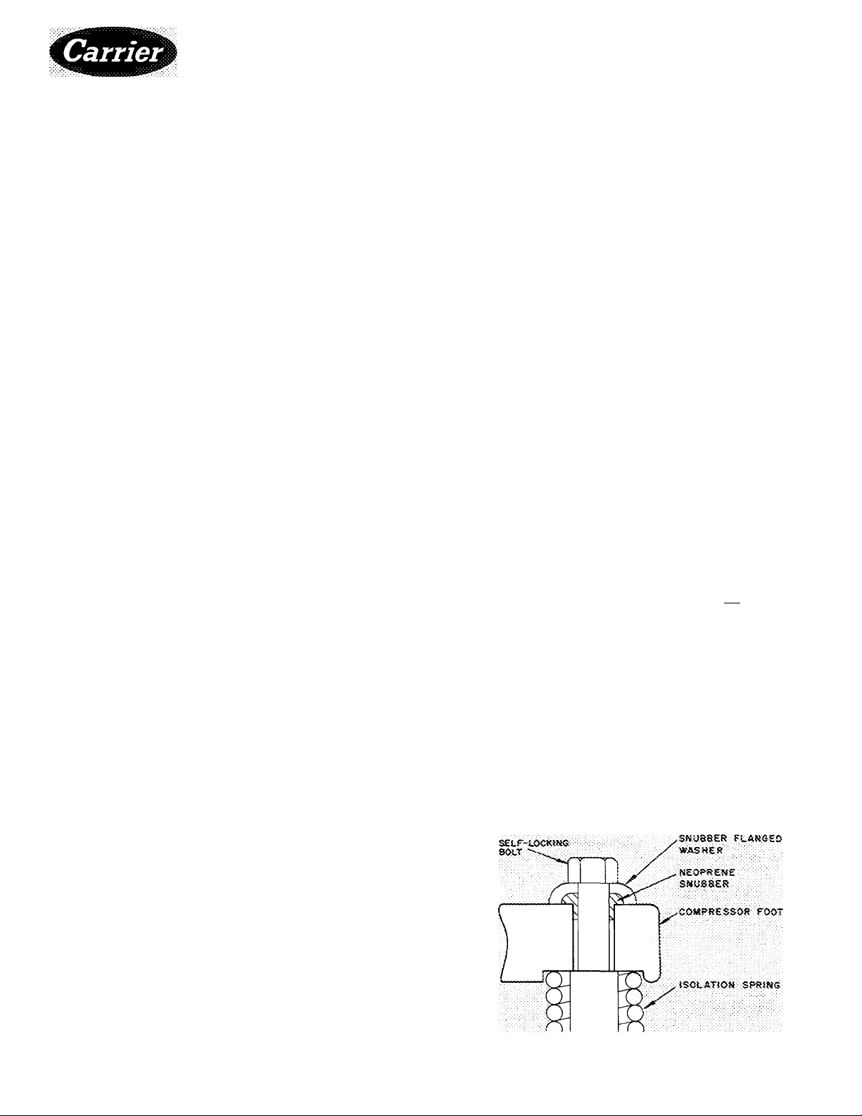
COMPRESSOR
Remove 4 self-locking bolts from compressor
mounting springs, and reassemble them with
flanged washers and neoprene snubbers as shown in
Fig. 1. Flanged washers and neoprene snubbers are
shipped in a cloth bag tied to compressor. Tighten
all 4 bolts. Then, loosen each until the flanged
washer can be moved sidewise. Check compressor
to see that it floats freely on its mounting springs.»
PIPING CONNECTIONS
Attach water supply and return line to con
nections indicated on condensing unit (Fig. 3).
Water leaving condenser should not be connected
directly into sewer lines; check local codes.
Attach refrigerant liquid and suction lines to
condensing unit (Fig 3),suction and discharge lines
to compressor unit (Fig. 2) Discharge line muffler
and check valve are factory supplied with 06E com
pressor units Install the muffler as close to shutoff
valve as possible and install the check valve in the
discharge line close to the muffler, on the down
stream side. When soldering or brazing piping to
valves, disassemble the valve or wrap it in wet cloth
to prevent damage by heat Allow flexibility in
Table 1 — Physical Data
COMPRESSOR UNIT 06E
1V022JW027
1 6ÔÔ i 640
CONDENSING UNIT 07E
OPERATING WEIGHT (Tb)
REFRIGERANT
COMPRESSOR 66E (06EV,EW)
(07EA,EB,ED):Di50i N265 i N i /5 i N299
Oil Charge, PP33-2(pt) 14 | i9 1 19 I 19
Normal Oil Pressure*
Oil Safety Switch Cut-in
High-Pressure Switch
Cutout Range
A022 :3027 ;B033Jp044_
l235{TM0'[T356JT56b '
D2.50 Ie265 Ie275 Ie?99^
Cutout
2 to 5 psi below cut-
300 to 400 psigt
W033
''650^^
R-22, R-502'
13 to 18 psig
9 to 13 psig
W044
320 pspt,
Differential (cutout,
Factory Settings!
cut-in)
Cutout
95 ± 1 5 psi ifixed)
335 ± 6 psig
260 i 6 psig
Cut-In
Low-Pressure Switch
Cutout Range
Differential (cutout, cut-in)
Factory Settings! Cutout
Low-Side Max Pressure
CONDENSER 69RE
Refrigerant 22
Max Storage Capacity (lb)**
Min Operating Charge (lb)
Max Operating Pressure
Refrig erant Side
Water Side
. 07E Condensing Unit Data
'Listed pressuies are above operating suction pressure (pressure
diffeieniial between suction and discharge pressures of oil
pump)
fAdjustable, but only by authorized personnel and with special
tool
:j Listed settings for R-22 For other refrigerants, reset to
pressures corresponding to saturation temperatures indicated by
the listed pressures
**Condenser 80% filled with liquid refrigerant at 104 F
Cut-in
240 t 7 ps:<3
175 3 7'ps>3‘ ■■■
5 to 1 00 psig (adj )
22 ± 8 psi (fixed)
24+4 psig
66 ± 4 psig
245 psig
022
3G
027
139 f
“j'y i
385 PC.Î9
250 psig
043
Î95
Fig. 1 — Compressor Mounting
670
37
© Carrier Corporation 1975
1276
Form 06E, 07E-5SI
Page 2
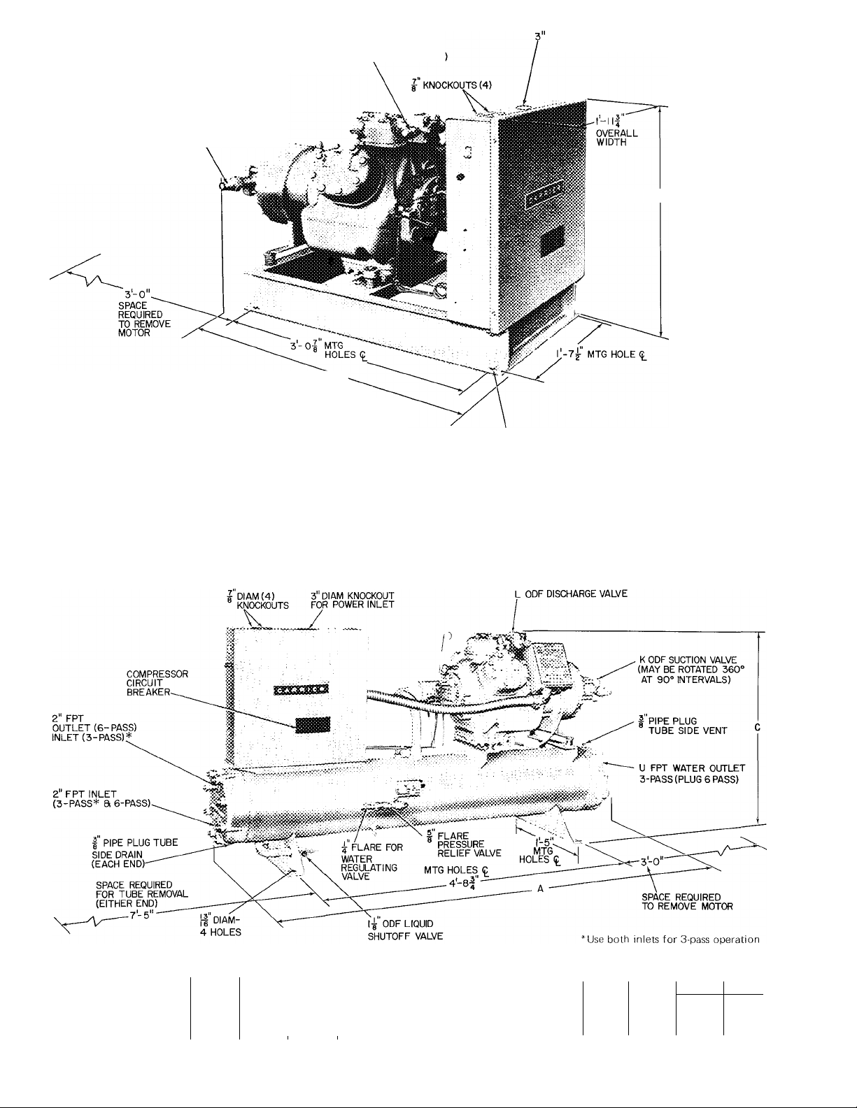
L ODF
SUCTION VALVE
(MAY BE ROTATED 360°
AT 90° INTERVALS)
*1 nstall pressure relief device in discharge line
Pressure relief setting is 465 psig
tOverall width includes projection of fuse
holders
M ODF*
DISCHARGE VALVE
(MAY BE ROTATED 180°
'A~
OVERALL
LENGTH
(INCLUDES
CONTROL BOX
OVERHANG)
DIAM KNOCKOUT
DIAM-4 HOLES
06E Hermetic Compressor Unit Dimensions
UNIT 06E
mMENMONS A
CONNECT Tons On ) u
M
V022
3-1 1 %
IV«
2-31| OVERALL HEIGHT
W027
3-1IV«
iVa“'
IV,
4~VVu
2v; '
iVa
JW0j44_
" 2Va ”■
1 Vs
Fig. 2 —06E Hermetic Compressor Units
UNIT 07E
DIMENSIONS (fi
Overall Width
Certified dimension drawings available on request.
HR
A022
A
6- 5 6- 5 6- 5
C 2-1 IV 3- 0
l-nVs
§027
1 -1 1V 1-1IV
07E Water-Cooled Condensing Unit Dimensions
§033
0044 _UNJT 07E^
6-7V CONNECTIONS (ii
2-1 1V2
3-2 Vs
2-3 Vs
Fig. 3 — 07E Water-Cooled Condensing Units
A022
K iVs IVs
L iVs IV«
U
2V
B027 B033
2V 2V
0044
2Vs
2Vs
IVs iVs
3
Page 3
Table 2 — Electrical Data (60-Hertz, 3-Phase)
(Circuit Breakers Selected for Units Using R-22)
VOLTS
UNIT
Compr
06 E W033
Cond
07 E B033
VOLTS
UNIT
Compr
06 E
Cond B027
07 E
KW — Maximum Power Input
LRA — Locked Rotor Amps
MTA — Must Trip Amps
MWA — Minimum Wire Amps Complies with NEC Section
RLA — Rated Load Amps
Supply Range — Units are suitable for use on electrical systems
NOTES:
1 Control voltage is 115 v for all units
Nomina 1
Supply Range
KW
V022
W027
W044
A022
B027
D044
Nominal
Supply Range
V022 24.8 36
W027
W033
W044
A022 22.6 32
B033 34.0 48 205 66
D044
24.8
33.6 103
37.6
55.1
22.6
31.4
34.0
50.4
KW RLA LRA
33.6
37.6
55.1 76
31.4 43 205
50.4
430-22
where voltage supplied to the unit terminals is
not below or above the listed range limits
RLA
g2
1 14
164
72 283
96
107 471 150
159 690 222
45
51
70 300
LRA
345
471 144 129
506 160
690
471 134 120 200
150
205 63 56 100
220 71
300
123 45
200
180-229
MTA
114
230
100
460 575 (See Note 5)
414-528
MTA
106
MWA FUSE
102
143
206 350
90
134
198 350 140
MWA
50
60
98 88
45
64
95
40 70 27
54 90
60 100 39 164 54
MÀX
AMPS
175
225
250
150
225 96
MAX MAX
FUSE
AMPS
80
no
150 60 240
150 60 240 84
2 Part-winding start all 200-, 230-volt 06E and 07E units; 460-,
575-volt 06EW044 and 07ED044 units
Across-the-line start: all 460-, 575-volt units except 06EW044
and 07ED044.
3. Factory wiring is in compliance with National Electrical Code
(NEC) Field wiring must comply with NEC and applicable
local codes Maximum incoming wire size to control center
terminal block is 250 MCM
4 The 06E compressor unit electrical data shown in the table
does not apply to 06E compressors used as an integral part of
other Carrier equipment Refer to the electrical data for the
particular application
-> 5 Units for use on 575 volts are available on special order
RLA
75
92
103 440 144
150 600
63
85 410 118 106
RLA
29 120 40 37 60
36 164 50 45 80
42
33
LRA MTA MWA
300
410
r 246
410
600
LRA MTA MWA
176
98
164
230
207-264
104
128 115
210
88
134
196
518-660
58 53 90
84 75
37 34
45
129 225
188
120
175
MAX
FUSE
AMPS
94
79 125
42
48
75
150
200
300
175
200
300
FUSE
AMPS
125
60
70
80
125
(Continued from page 1.)
suction line so compressor suction valve may be
moved aside for access to suction strainer.
A solenoid valve is necessary for single pump
out control used on 06E and 07E units. Install the
valve (field supplied) in the liquid line, just before
the expansion valve. A filter-drier of adequate size
should be installed in liquid line between con
denser and solenoid valve.
Pressure relief valve located on side of con
denser will open to relieve excessive pressure,
allowing refrigerant to escape. Most local codes
require piping from valve to outdoors.
Refer to Carrier System Design Manual for
standard piping techniques.
ELECTRICAL REQUIREMENTS
Eield wiring must comply with local and
national codes. See Table 2.
Install a branch circuit fused disconnect of
adequate size to handle starting current. The
disconnect must be within sight of the unit and
readily accessible, in compliance with National
Electrical Code (NEC), Section 440—14.
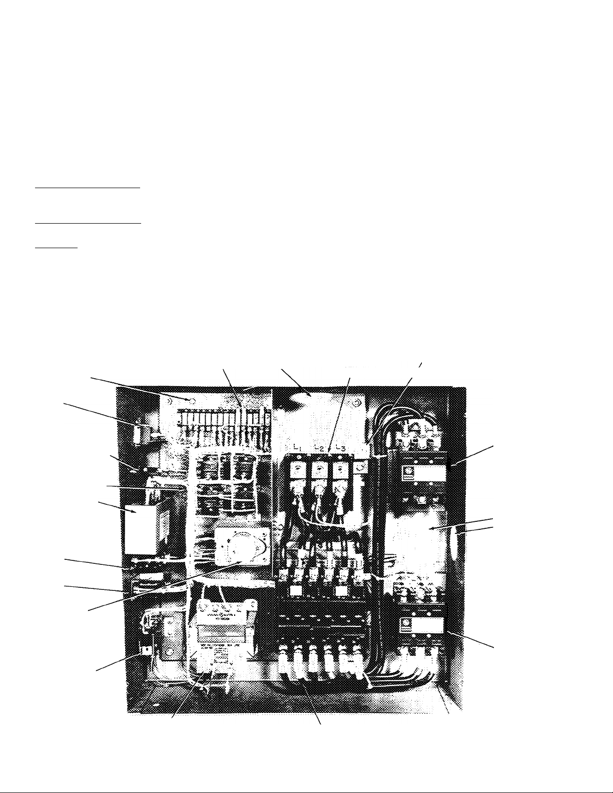
Line power is brought into control center thru
indicated opening. Connect line power supply to
terminal block TB1; connect power leads to
terminals LI, L2 and L3. Connect control circuit
power supply (115 volts) to terminals 1 and 15 on
terminal block TB2. Refer to Eig. 4.
Wiring connections for field-supplied equip
ment are shown on diagram attached to unit (or in
wiring diagram booklet).
Discharge line limit thermostat supplied with
06EV,W compressor units is installed on discharge
line as close to compressor as possible.
1. Place mounting plate on discharge line and
solder in place.
Easten the thermostat to plate with screws
2.
supplied.
Cover switch with insulation and secure insula
3.
tion at each end with straps.
Connect thermostat in series with Ml and M2
4.
overloads, between terminals 2 and 4 on termi
nal block TB2.
ACCESSORIES
PACKAGE NUMBER
07EA900021
07EA900061
DESCRIPTION
Control Circuit Transformer
Gage Panel
1276
Page 4
REFRIGERANT CHARGING
Evacuate, Dehydrate and Leak Test the entire
refrigerant system by methods described in Carrier
Standard Service Techniques Manual, Chapter 1,
Sections 1-6 and 1-7. Use sight glass method to
charge system. See Section 1-8 of Service Tech
niques Manual for details.
CHARGE THE SYSTEM to a clear sight glass while
holding saturated condensing pressure constant at
125 F (air-cooled systems) or 105 F (water-cooled
systems) Add additional refrigerant to fill con
denser subcooler coils.
07E Condensing Units - After clear sight glass is
obtained, add charge until liquid refrigerant
reaches condenser liquid level test cock.
06E Compressor Units — See condenser data for
additional charge required to fill subcooler.
All Units — Stamp type of refrigerant and amount
of charge on unit informative plate
INITIAL START-UP
Crankcase heater should be energized a mini
mum of 24 hours before starting unit.
Check to see that oil level is approximately 1/3
up on the compressor sight glass.
Open water supply valve and allow water to
reach condenser. (Turn condenser fan on when the
compressor unit is applied with air-cooled con
denser.)
Backseat the compressor suction and discharge
shutoff valves, open liquid line valve at receiver.
Start evaporator fan or chilled water pump.
Start Compressor — Push the control circuit
START-STOP-RESET switch to “Start.” The timer
motor starts immediately. Depending on the posi
tion of the timer, the compressor start is delayed
for 12 seconds to approximately 8 minutes. Check
oil pressure after compressor has run a few
minutes, the pressure should be 12—18 psi above
the suction pressure After about 20 minutes of
operation, stop the compressor. Allow it to be idle
for about 5 minutes, then observe the oil level in
the sight glass. If the oil level is below the bottom
of the sight glass, refer to the Carrier Standard
Service Techniques Manual, Chapter 1, Section
1-11, for adding oil. The proper oil level for the
06E compressor is approximately 1/3 up on sight
glass.
là
CONTROL POWER TERMINAL STRIP (TBg)
GROUND SCREW
START-STOP-RESET
SWITCH
CONTROL CIRCUIT
FUSE(S)
(2 ON 50-Hz UNITS)
CONTROL RELAYS
SENSOR MODULE
(SOLID STATE
COMPRESSOR MOTOR
PROTECTION)
HIGH PRESSURE
SWITCH
LOW PRESSURE
SWITCH
TIMER MOTOR
(4-FUNCTION TIMER)
MAIN POWER
INLET,
MAIN POWER
TERMINAL
BLOCK (TB|)
EQUIPMENT GROUND
'connection
COMPRESSOR
CONTACTOR
OUTLET FOR
WIRING TO
COMPRESSOR
06E
07E
OIL PRESSURE
SAFETY SWITCH
1276
ACCESSORY TRANSFORMER
(60-Hz UNITS ONLY)
MAIN POWER
CIRCUIT BREAKER
Fig. 4 — Control Center — 06E and 07E
4
COMPRESSOR
CONTACTOR
(PART-WIND)
Page 5
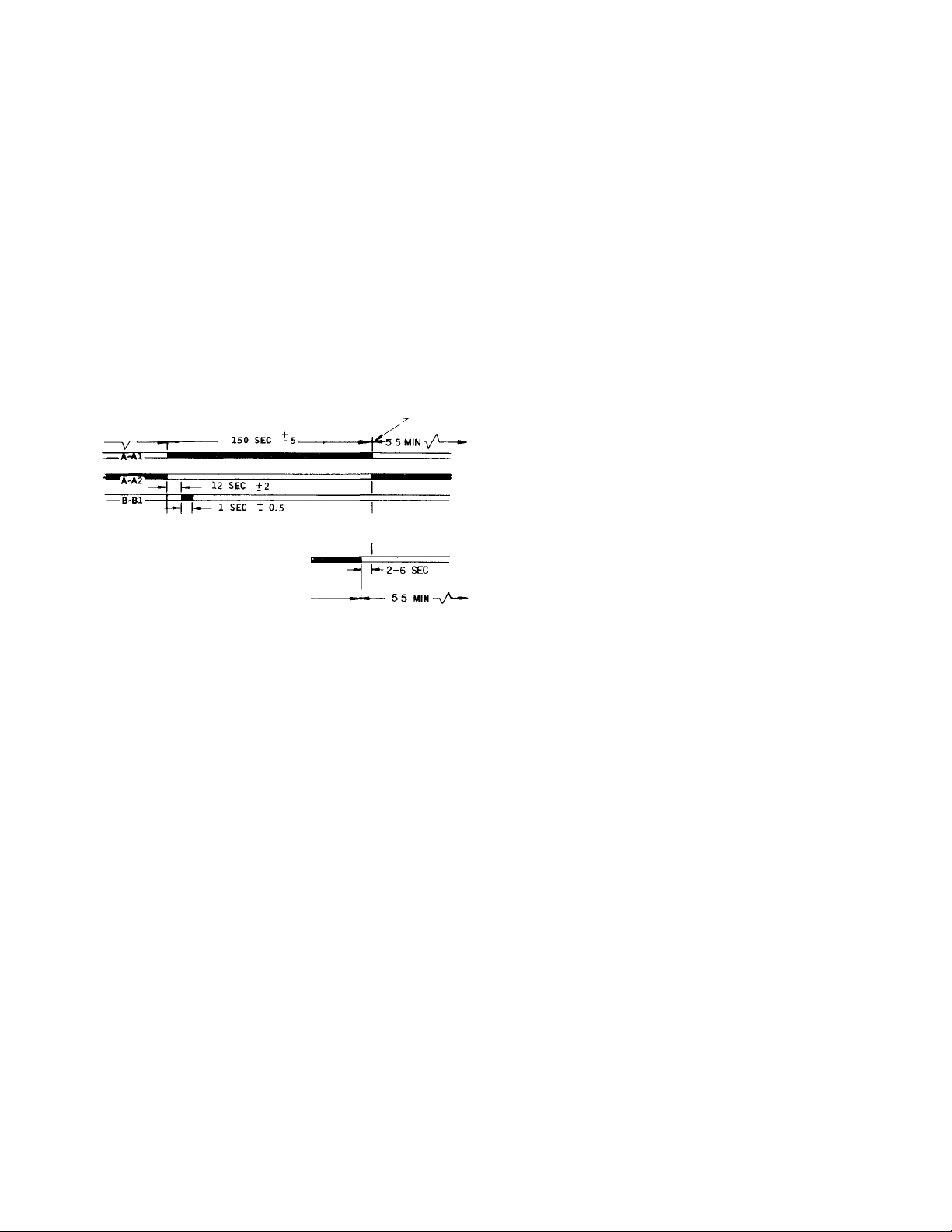
Timer Functions (See Fig. 5 — Tinier Cycle)
1. Switch A (contacts A-Al and A-A2) provides
Time Guard® function. Start of compressor is
delayed approximately 5.5 minutes after shut
off. The minimum time between starts of
compressor is 8 minutes.
2. Switch B (contacts B1 and B—B2) starts
compressor and de-energizes the crankcase
heater. These contacts also provide one-second
time delay for part-winding start.
3. Switch E (contacts E—El) provides approxi
mately 40-second bypass of oil-pressure switch
(OPS) at start-up. Compressor will shut off if
sufficient oil pressure does not build up.
4. Switch D (contacts D—Dl) bypasses the lowpressure switch (EPS) for 2.5 minutes at start
up for winter start control.
(BLACK DENOTES CLOSED CONTACTS)
0 MIN OR
8 MIN
»TT?*
-'E-El-
-xA-
High-Pressure Switch — Check by throttling con
40 SEC +5
2-6 SEC
---
150 SEC
Fig. 5 — Timer Cycle
PROTECTION DEVICES
TIMER POSITION DURING
UNIT OPERATION-
denser water or blocking air flow on air-cooled
units, allowing head pressure to rise gradually.
Check discharge pressure constantly throughout
procedure. Compressor should shut off within 10
psi of values shown in Table 1.
Low-Pressure Switch — Check by slowly closing
suction shutoff valve or by completely closing
liquid line shutoff valve. A decrease of suction
pressure will follow. Compressor should shut off
within 4 psi of values shown in Table 1.
Oil Pressure Switch (OPS) protects against damage
from loss of oil and failure of pressure buildup
during start-up. Switch time delay (approximately
35 seconds) is derived from being properly wired
to the ambient and voltage insensitive Time Guard
timer. If OPS locks out unit, det e rm ine an d c o r r e c t
th e c a u s e (such as loss of compressor oil or flooded
compressor) be f o r e r e s ta r t in g uni t Restart by
pushing the control circuit switch on unit control
box to “Stop” then to “Reset.” Failure to correct
the cause of the OPS lockout will constitute abuse.
Eq ui p m e n t f a il u r e d u e to a b u s e i s n o t c o v e re d by
th e Warr a n t y .
Time Guard Control protects compressor against
short cycling. See Start Compressor.
Crankcase Heater prevents absorption of liquid
refrigerant by oil in crankcase during brief or
extended shutdown periods. Source of 115-volt
power is the auxiliary control power, independent
of the main unit power. This assures compressor
protection even when main unit power disconnect
switch is off.
N ev e r o p e n any s w it c h o r d i sc o n ne c t t h a t w i ll
de - e n e rg i z e th e c r a n k c a s e h e a te r u n l e ss u n i t i s
be i n g se r v ic e d or is to be s h u t d o w n fo r a
pr o lo ng e d pe r io d Af te r a p r o l o n g e d s h u t d o w n or a
se r vi c e jo b , en e r g iz e th e cr a n k c a se he a t e r f o r 2 4
ho u r s b e f o r e s ta r t ing th e co m pre s s o r .
Compressor Motor Protection consists of 3 tem
perature sensors embedded in motor windings and
connected to a solid state module in unit control
box.
When an overtemperature condition causes
module to shut compressor off, push control circuit
STOP switch. Investigate cause of compressor shut
down and correct. After compressor cools, push
control circuit START-RESET switch. Compressor
will restart after Time Guard delay period.
SOLID STATE MODULE is checked by applying
unit control voltage to terminals T1 and T2 (see
label diagram), then checking for continuity across
terminals Ml and M2. If no continuity between Ml
and M2, check temperature sensor resistance using
a volt-ohmmeter. If all sensors check below 95
ohms (180 F) and there is no continuity between
module terminals Ml and M2, replace module.
CAUTI O N: D o no t u s e a ba t te r y p o w e r ed t e s t
la m p t o ch e c k s e n so r s E x c e s si v e cu r r e n t ca n
ca u s e d a ma g e
If one sensor fails, it can be jumpered out of
the circuit with a 75 ohm, or higher, resistor (rated
at 2 watts or higher) across the proper sensor
terminal and common terminal. If a short to
ground in sensor circuit is indicated, replace
compressor motor.
CAPACITY CONTROL SYSTEM
Capacity Control Valve(s) is controlled by suction
pressure and actuated by discharge pressure. Each
valve controls 2 cylinders. On start-up, controlled
cylinders do not load up until differential between
suction and discharge pressure is 10 psi (see Fig. 6).
D o no t us e au t o m a t i c p u m p d o wn c o n tr o l on
06 E , 0 7 E u n i ts e q u i p p ed wi th u n l o a d e r va l v e s . U s e
sing l e p u m p o u t o r s o le n o i d d r o p (mi n im um p r o
te ct i o n ) c o n tr o l
Capacity Control Valve Adjustments
CONTROL SET POINT (cylinder load point) is
adjustable from 0 psig to 85 psig. Pressure differ
ential between cylinder load-up point and cylinder
unload point is adjustable from 6 psi to 22 psi.
Page 6

PRESSURE DIFFERENTIAL
ADJUSTMENT SCREW
SEALING BYPASS CYLINDER
CAP PISTON HEAD
BYPASS PASSAGE
CONTROL SET
POINT ADJ NUT
POPPET VALVE'
BLEED ORIFICE'
DISCHARGE MANIFOLD
SUCTION PRESSURE
nZH DISCHARGE PRESSURE
DISCHARGE SUCTION
VALVE PISTON VALVE
UNLOADED OPERATION
COMMUNICATES WITH
SUCTION MANIFOLD
-SUCTION MANIFOLD
l~~~1 DISCHARGE PRESSURE
Fig. 6 — Capacity Control Valve Operation
TO REGULATE CONTROL SET POINT (Refer to
Fig. 7) —Turn adjustment nut clockwise to its
bottom stop. In this position, set point is 85 psig.
Control set point is then regulated to desired
pressure by turning adjustment nut counterclock
wise. Each full turn decreases set point by 7.5 psig.
Approximately 11 1/2 turns counterclockwise will
decrease control set point to 0 psig. Table 3 shows
the steps of control.
PRESSURE DIFFERENTIAL ADJUSTMENT
(Fig. 7) — Turn differential adjusting screw counter
clockwise to its back-stop position. In this posi
tion, differential is 6 psi. Pressure differential is set
by turning adjustment screw clockwise. Each full
turn increases differential by 1.5 psi. Approxi
mately 10 turns clockwise will increase pressure
differential to 22 psi.
LOADED OPERATION
CONTROL
TO PREVENT REFRIGERANT LEAKAGE)
Fig. 7 — Capacity Control Valve
Page 7

Capacity Control Valve Operation (Fig. 6)
LOADED - When suction pressure is above con
trol point, the poppet valve closes. Discharge gas
bleeds into valve chamber, the pressure closes
bypass piston and cylinder bank loads up. Dis
charge gas pressure forces check valve open, per
mitting gas to enter discharge manifold.
UNLOADED — When suction pressure drops below
valve control point, the poppet valve opens. Dis
charge gas bleeds from behind bypass piston to
suction manifold. Bypass piston opens, discharge
gas is recirculated back to suction manifold and
cylinder bank is unloaded. Reduction in discharge
pressure causes check valve to close, isolating
cylinder bank from discharge manifold.
CAPACITY
CONTROL
VALVE
CAP SCREWS
(NONINTERCHANGEABLE
WITH FLANGE COVER
CAP SCREWS)
Table 3 — Steps of Control
COMPRESSOR STEPS
06 E
CONDENSING
UNIT 07E
06EV022
07EA022
06EW027
07EB027
06EW033
07EB033
06EW044
07 ED 044
NOTE:
Capacity control valve (Fig 7) factory settings for 4-cylinder
units are: 69 psig control set point (cylinder load point), 10 psig
differential (59 psig cylinder unload point) Settings for 6-
cylinder units are: left cylinder bank control set point is 70 psig,
differential is 10 psig; right cylinder bank control set point is 68
psig, differential is 10 psig
1 2 3
No. % No. % No.
Cyl Cap. Cyl
4 100 2
100
6
100
6
6 100 4 67
4
4
Cap. Cyl
50
67
67
2 33
2 33
2 33
-
%
Cop.
-
Service Replacement Compressors are not equip
ped with capacity control valves. Side bank
cylinder head(s) is plugged with spring loaded
piston plug assembly(ies). Compressor will run
fully loaded with piston plug(s) in place.
Transfer original capacity control valve(s) to
corresponding cylinder bank(s) in replacement
compressor (ensures proper valves are used with
correct setting). Install piston plug assembly(ies)
into original compressor for sealing purposes.
Three alien head cap screws hold capacity
control valve in place (Fig. 8). Remove screws
using a “cut down” 3/16-in. alien wrench, and pull
valve from cylinder head.
Remove same number of piston plugs from
replacement compressor as number of unloaders
supplied with original compressor. Three alien head
cap screws hold piston plug assembly in place.
Remove flange cover, gasket, spring, and piston
plug (Fig. 9). A tapped hole is provided in piston
to allow it to be pulled out. Hole has same thread
diameter as cap screws removed above.
Fig. 8 — Removal of Capacity Control Valve
BYPASS PISTON PLUG
SPRING
CAP SCREWS
(NONINTERCHANGEABLE
WITH CONTROL VALVE
CAP SCREWS)
GASKET
-FLANGE COVER
Fig. 9 - Removal of Bypass Piston Plug
CONDENSER MAINTENANCE (07E Units)
To inspect and clean condenser, drain water
and remove condenser heads. To drain condenser,
shut off water supply and disconnect inlet and
outlet piping. Remove drain plugs and vent plug.
With condenser heads removed, inspect tubes
for refrigerant leaks. (Refer to Carrier Standard
Service Techniques Manual, Chapter 1, Section
1-6, Leak Testing, for instructions.)
Clean condenser tubes with nylon brush (avail
able from Carrier Service Department). Flush water
thru tubes while cleaning. If hard scale has formed,
clean tubes chemically. Do not use brushes that
will scrape or scratch tubes.
For chemical cleaning solution, use inhibited
hydrochloric acid solution (Oakite 32). Handle
acid cautiously. Clean condenser by gravity or
forced circulation (Fig. 10 and 11). For average
scale deposits allow acid solution to remain in
condenser overnight; for heavy deposits, allow 24
hours. Drain condenser and flush with clean water.
NOTE: Protect condenser from freezing when
ambient is below 32 F by draining water from
system or adding antifreeze to water.
Page 8

Before assembly, coat all parts with compressor
4.
oil and clean and inspect all gasket surfaces.
Replace all gaskets with new factory-made
gaskets. See Table 4 for torque values.
After reassembly, evacuate compressor and
5.
open suction and discharge valves. Restart
compressor and adjust refrigerant charge.
Legend (Fig. 12)
Fig. 10 — Gravity Circulation
ceOTarcGAt. pcwp sas vemt-
30 OPM AT 35' HEAD
PUMP. • " ^
SUCT:ON
PRl«WS /VAl.VE£\..
, REMCA'E WATER
^ REGULATINC- valve
: ClXSt VENT PIPE
; VALVE WHEN
; PUMP IS
: RUMNWG
COiv-CEAiSES
Fig. 11 — Forced Circulation
REMOVING, INSPECTING AND
REPLACING COMPONENTS (Fig. 12)
Service Notes
1. All compressors have interchangeable valve
plate assemblies, unloader valves and oil pump
bearing head assemblies. For replacement items
use Carrier Specified Parts.
2. Before compressor is opened, the refrigerant
must be removed from it by the Pumpdown
method.
Start compressor, close suction shutoff
a.
valve, and reduce crankcase pressure to 2
psig. (Jumper low pressurestat.)
Stop compressor and isolate from system by
closing discharge shutoff valve.
c.
Bleed any residual refrigerant. Drain oil if
necessary.
3. After disassembly, clean all parts with solvent.
Use mineral spirits, white gasoline or naptha.
-
Compressor Motor —
1
Stator and Rotor
Motor Key
2
Rotor Plate Washer 31-Pump Rotor
3
Rotor Lock Washer 32
-
4
Rotor Lock Bolt
5
-
—
Motor Lock Bushing 34-Pump Vane Spring
6
7_Roll Pin
_
Acorn Nut and Gasket
8
Ring Spacer
9
—
Junction Box
10
Terminal Plate Assembly
11
—
Terminal Bolt Assembly
12
—
Terminal Bolt Assembly
13
-
Cover Plate
14
Hex Head Screw
15
-
Cylinder Head Bolts
16
—
Connecting Rod and
17
Piston Assemblies
Compressor Crankcase
18
Motor End Cover
19
-
-
Cylinder Head —
20
Center Bank
Cylinder Head — Capacity
21 -
Control Side Bank
Internal Relief Valve
22 -
_
Crankcase Oil Filter
23
Screen
- Oil Sight Glass Assembly
24
-
Oil Sight Glass 0-Ring
25
Gasket
Oil Sight Glass Screw
26
Oil Sight Glass Lock
27
Washer
_
Pipe Plug Gasket
28
(hex head)
-
Bottom Cover Plate
29
30—Pump End Bearing
Pump Vane
-
33 Pump Vane Spring
35“Retaining Spring
_
Oil Feed Guide Vane
36
Oil Feed Guide Vane
37
-
38_Oil Pump Drive Segment
_
Screw, Soc Head
39
_
40
Screw, Soc Head no 10
41-Cover Plate
42-Cover Plate Cap Screw
Oil Relief Piston
43
-
44
Crankshaft
45_Bearing Washer
_
46
Piston Ring (Oil and
47__Piston, Piston Pin and
48-Connecting Rod and
49-Valve Plate Package
Valve Plate
50
51-Discharge Valve Stop
52-Discharge Valve
53_Valve Stop Support
_
Cap Screw, Valve Stop
54
55—Suction Valve
Head Package
Guide
Spring
1/4 - 28 X 5/8 in
- 32 X 1/2 in
Compression)
Retaining Ring
Package
Cap Assembly
Page 9

.........
^53) \ ' V.
(SEE LEGEND PAGE 8)
V-
_________
^ ^
Fig. 12 — 06E Compressor Components
Page 10

Table 4 — Torque Values
SIZE
THREADS
DIAM
PER IN.
(in.)
27 (pipe)
Xe
%
%
‘/4
Xe
%
%
Xa
X
V,
X
X
No. 6
No. 10 32
18
20
28
18 (pipe)
16
18 (pipe) 30-40
14
13
11
18
16
32
TORQUE
RANGE
(Ib-ft)
8-12
Pipe Plug — Crankshaft
20-25 Pipe Plug — Crankcase
8-10
Conn. Rod Cap Screw
Junction Box
8-12
Sight Glass
3-5
14-18
14-18
14-18
15-24
15-24
30-40
30-40
30-40
25-30
55-65
55-65
90-100
90-120
90-120
90-120
90-120
60-75
Oil Pump Drive Segment
Unloader Valve
Discharge Valve Stop
Cover Plate — Pump End
Bearing Head
Discharge Service Va!ve(4 cyl)
Bottom Plate — Crankcase
Compressor Foot
Terminal Block
Oil Plug — Pump End Bearing
Head
Terminal Bolts
2-4
Pipe Plug — Junction Box
Motor End Cover
Pump End Bearing Head
Cyl inder Head
Discharge Service Valve (6 cyl)
Suction Service Valve (4 cyl)
Suction Service Valve (6 cyl)
Rotor Lock — Crankshaft
Oi 1 Drain Plug
Stator Lock
105
Check Valve Body — Crankcase
1-2
Oil Pump Drive Segment
4-6
Terminal Screw
4-6
USAGE
OIL
PRESSURE
TAP
^ drive segment
CAP screws
PUMP END
BEARING HEAD
OIL FEED GUIDE VANE
AND SPRING
Fig. 13 — Removing Pump End Bearing Head
LUBRICATION SYSTEM
Testing Oil Pump — An oil pressure tap is located
above oil pump cover plate (Fig. 13). Oil pressure
should be 12—18 psi above suction pressure.
OIL FILTER SCREEN is accessible thru bottom
cover plate. Remove and inspect strainer for holes
and dirt. Clean it with solvent and replace.
Oil Pump and Bearing Head — The oil pump
assembly is contained in the pump end bearing
head aluminum casting. (The pump end main
bearing is a machined part of this casting — no
insert bearing.)
REMOVE bearing head from crankcase and dis
assemble oil pump. Drive segment cap screws must
be removed before bearing head can be removed
(Fig. 13). Remove pump vane assemblies from
both sides of bearing head. Push the pump rotor
out of the bearing head by pushing against the
bearing side of the rotor. Check all parts (Fig. 14)
for wear and damage.
REPLACE
1. Install the rotor retaining ring in the ring groove
of the pump rotor with chamfered edge toward
compressor. Compress retaining ring, and insert
pump rotor into bearing head.
1 — Cover Plate
2 — Oil Feed Guide Vane Spring
3 — Oil Feed Guide Vane
4 — Drive Segment
5 — Pump Rotor
6 — Pump End Bearing Head
7 — Pump Vane
8 — Pump Vane Spring
9 — Pump Vane Spring Guide
10 — Retaining Spring
11 — Pump End Main Bearing
12 — Oil Relief Piston
Fig. 14 — Pump End Bearing Head Package
10
Page 11

2. Place the pump vanes, pump vane spring with
guides, and snap rings into the bearing head.
Compress the springs and force the snap rings
into their grooves. (Insert snap rings with flat
side against casting.)
3. Bolt bearing head to crankcase (use 55 to 65
Ib-ft torque). Bolt drive segment to crankshaft.
4. Insert the oil feed guide vane with large
diameter inward. Place oil feed guide vane
spring over small diameter of guide vane.
5. Install pump cover plate.
CYLINDER HEADS (Fig. 12)
Disassemble cylinder heads by removing cap
screws, and prying up on side lifting tabs to break
heads loose from valve plates. Do not hit cylinder
heads to break loose.
Check heads for warping, cracks and damage to
gasket surfaces. When replacing cylinder head,
torque cap screws 90 to 100 Ib-ft (prevents high to
low side leak in center portion of cylinder head
gasket).
Pressure Relief Valve — This safety device is
located in center cylinder bank (6-cylinder com
pressors, Fig. 15) or under discharge service valve
(4-cylinder compressors). The valve relieves refrig
erant pressure from high to low side at 400 psi
pressure differential. Check valve for evidence of
leaking. Change if defective or if valve has ever
opened due to excessive pressure. Use a standard
socket-type screwdriver to remove and replace
valve.
Reassemble — Do not interchange valves. Install
suction valves on dowel pins. Place valve plate on
cylinder deck, and reinstall discharge valve
assembly. Retorque discharge valve stop cap screws
to 16 Ib-ft. Replace cylinder head. (Be sure tab on
cylinder head gasket is lined up with tabs on
cylinder head and valve plate.)
Fig. 15 — Pressure Relief Valve Removal
VALVE PLATE
SUCTION VALVE ?
SEATS
(VALVE PLATE)
SUCTION AND DISCHARGE VALVE
PLATE ASSEMBLY (Fig. 12)
Test for leaking discharge valves by pumping
compressor down and obseiving suction and
discharge pressure equalization. If a discharge valve
is leaking, their pressures will equalize rapidly.
Maximum allowable discharge pressure drop is 3
psi per minute.
If there is an indicated loss of capacity and
discharge valves check properly, remove suction
and discharge valve plate assembly and inspect
suction valves.
Disassemble — Remove cylinder head.
1. Remove discharge valve assembly: cap screws,
valve stops, valve stop supports and valves.
2. Pry up on side lifting tab to remove valve plate
and expose suction valves (Fig. 16). Remove
suction valves from dowel pins.
Inspect valves and valve seats for wear and
damage (see Wear Limits, Table 5). Replace valves
if cracked or worn. If valve seats are worn, replace
complete valve plate assembly.
SUCTION VALVES <
Fig. 16 — Valve Plate Removed
TERMINAL PLATE ASSEMBLY
Removal — Disassemble junction box from termi
nal plate, and remove cap screws holding terminal
plate to compressor. Mark all motor leads so they
can be reassembled correctly to terminal plate.
Loosen alien head screws holding motor leads to
terminal plate (Fig. 17). Remove terminal plate.
Power Lead Terminal Stud — Disassemble only if
leaking refrigerant or if resistance to ground is low.
If there is a short to ground, replace complete
terminal plate assembly.
DISASSEMBLE (Fig. 18)
1. Unscrew terminal, terminal locknut, and termi
nal bolt assembly hex nut.
11
Page 12

2. Push terminal bolt thru terminal plate and
remove insulating washers.
Inspect for grounds, insulation breakdown, and
sufficient life remaining in terminal seal bush
ings. It is recommended that disassembled
terminal stud assemblies be replaced with new
parts.
REASSEMBLE
1. Refer to Fig. 18 for position of terminal
assembly parts (washers are color coded).
2. Tighten terminal bolt assembly hex nut only
enough to stop escape of refrigerant gas (max
imum recommended torque is 4 Ib-ft). Do not
tighten nuts so terminal insulation washers are
flush with mounting plate.
ALLEN HEAD
SCREWS (T)
Table 5 — Wear Limits — 06E Compressor
FACTORY
COMPRESSOR PART
MOTOR END
Main Bearing Diameter
Journal Diameter
PUMP END
Main Bearing Diameter
Journal Diameter
CONNECTING ROD
Bearing Diameter
(After Assembly)
Crankpin Diameter
THRUST WASHER
(Thickness)
CYLINDERS
Bore
Piston Diameter
Wrist Pin Diameter
Con. Rod Wrist Pin ID
Piston Ring End Gap
Piston Ring Side
C learance
VALVE
THICKNESS
END CLEARANCE
""Maximum allowable wear above maximum or below minimum
factory tolerances shown For example difference between
main bearing diameter and journal diameter is 0035 in
(1 8760 — 1 8725) per factory tolerances Maximum allowable
difference is 0045 in (0035+ 001)
Suctic
D ischarge
TOL. (in.)
Max
1 .8760
6260
1 7515
2 6885
8755
007
003
0315
0255
0225
031
1 8725
6233
7483
155
2 6817
8748
002
001^
0305
0245*
0215
MAXIMUM
ALLOWABLE
WEAR* (in.)
001"
001"
002*
002
002
001
001
015
002
002
002
010
Fig. 17 — Removing Terminal Plate Assembly
■r--7.7X
TERMINAL BOLT ASSEMBLY
TERMINAL INSULATION WASHER
INSULATION WASHER
■TERMINAL INSULATION BUSHING
-----
TERMINAL SEAL BUSHING
TERMINAL INSULATION
WASHERS(GRAY)
TERMINAL INSULATION
WASHER
LOCK WASHER
(SPRING)
TERMINAL LOCKNUT
TERMINAL SEAL WASHERS
(RED)
TERMINAL INSULATION
BUSHING
PLATE WASHER
HEX NUT
■TERMINAL
Fig. 18 — Power Lead Terminal Stud Assembly
MOTOR REMOVAL
Motor End Bell — Remove motor end bell care
fully to prevent damage to the stator. Use three
7/16 — 14x5 in. studs for guides and support. In
spect suction strainer in end bell. Clean it with sol
vent or replace if broken or corroded.
Rotor — Bend rotor lock washer tab backward and
remove rotor lock bolt. If crankshaft turns, pre
venting lock bolt from being loosened, remove a
cylinder head and valve plate and place a rubber
plug (06R suction plug) on top of one piston (Fig.
19). Replace valve plate assembly and cylinder
head (only two bolts required to hold cylinder
head in place). Proceed to remove rotor lock bolt,
lock washer and plate washer.
Use a jackscrew to remove rotor (Fig. 19).
Insert a brass plug into rotor hole to protect end of
crankshaft from jackscrew. Support rotor while it
is being removed to prevent stator damage. Re
move ring spacer between rotor and crankshaft.
Clean rotor thoroughly with solvent. If stator is
to be replaced, a matching rotor must be used.
12
Page 13

Stator is a slip fit in motor housing. It is held in
place by both an axial key and a locking assembly
consisting of an acorn nut, locking pin, motor lock
bushing and a washer. Remove acorn nut and
washer. Back out locking pin and bushing. With
draw stator (Fig. 20). Axial key positions stator
and crankcase. If necessary, heat crankcase motor
housing (not over 20 to 30 F above stator temp).
Check stator for damage to windings and lead
wires. Use a megohmmeter to check for grounds or
shorts between windings.
MOTOR REPLACEMENT
Stator and Rotor — Install stator halfway into
housing. Insert the terminal leads first, guiding
them to terminal plate opening as stator is being
inserted.
Replace ring spacer (Fig. 12) on crankshaft.
Ease rotor onto shaft until it begins to feel snug.
Insert rotor key, and push rotor the remainder of
the way on shaft. Replace rotor lock bolt with lock
washer and plate washer.
CAUTI O N. Do n o t p u s h st a to r in c o m p l e te l y
un t i l ro t o r i s i n p l a c e
RUBBER PLUG
JACKSCREW
Fig. 19 — Removing Rotor
VALVE PLATE
STATOR LOCKING
ASSEMBLY
^OTOR LOCK BOLT
Push stator into housing until it lines up correctly
with rotor (Fig. 21).
Line up keyways in stator and crankcase and
replace stator locking assembly, then drive key into
keyway and stake over keyway in stator to secure
key. When a new motor is being installed, the
stator must be drilled and a new locking pin and
motor lock bushing used (see Fig. 22 and instruc
tions). Connect stator leads to proper terminals on
terminal plate. Refasten terminal plate and junc
tion box to compressor. Replace motor end bell
using studs for support. Remove rubber plug (if
used) from piston head. Replace valve plate
assembly, cylinder head, and terminal plate
assembly. Torque in 12 bolts holding terminal
plate to crankcase at 30—40 Ib-ft.
END
V STATOR
Ll
1
TURN
1
■ . }■
1
END
RING
1
ROTOR CENTER LiNS
D
ASSEMBLY
LOCKING PIN BOSS
STATOR
WASHER
Fig. 20 — Removing Stator
LOCKING PIN
13
Fig. 21 — Motor Alignment
REENEC
ENOS
..
MOTOR LOCK BUSHfNG
locking RiN
..........
S~ATCR CORE
Fig. 22 — Stator Locking Assembly
C0'M»R£SS0R
0AST^NG
Page 14

REMOVE
1. Acorn nut and washer.
2. Back out locking pin and bushing.
REPLACE
1. Screw in locking pin bushing until it rests on
stator core.
2. Wrap a piece of tape around 3/8 in. drill bit,
2-1/16 in. from cutting edge.
3. Ream out bushing (3/8 in. drill) and drill into
stator core until tape is flush with top of
bushing. (Remove drill chips.) Back off locking
pin bushing 1/8 of a turn.
CAUTI O N' B e f o r e d r il li n g , b e s u re sta t o r v e n t
ho l e s do no t l in e up wi t h l o ck i n g p i n h o l e . V e n t
ho l e s ar e d r i ll e d h o r iz o n t a ll y t h r u s ta t o r , a n d
ca n b e s e e n f r o m e n d b e l l s id e .
4. Tap locking pin into position. (Top of bushing
should be approximately 1/16 in. above top of
pin.)
5. Peen top of bushing over roll pin.
6. Replace washer and acorn nut.
COMPRESSOR RUNNING GEAR REMOVAL
Connecting Rod and Piston Assembly — Remove
cylinder heads, valve plate assemblies, crankcase
bottom cover plate, oil filter screen, and con
necting rod caps (Fig. 23.) (Label caps and rods so
they may be reinstalled in same place on crank
shaft.) Push connecting rod and piston assemblies
up thru cylinder deck. Disassemble connecting rods
from pistons by removing retaining rings and
piston pins. Remove oil and compression rings from
piston. (Keep each connecting rod and piston
assembly together for proper reassembly.) Check
all parts and crankpin journals for wear (refer to
Table 5 for wear limits).
Crankshaft — Remove pump end bearing head and
rotor. If connecting rod and piston assemblies are
still in place, remove connecting rod caps and push
piston assembly up into cylinder for crankshaft
clearance. Pull crankshaft out thm pump end
opening. Inspect crankshaft journals for wear and
tolerances shown in Table 5. Check oil passages
and clean if clogged.
Pump End Main Bearing is a machined part of the
oil pump and bearing head casting. Disassemble
bearing head. If bearing is scored or worn, replace
the complete bearing head.
Crankcase and Motor End Main Bearings are not
field replaceable. If bearings are worn or damaged,
replace compressor.
CONNECTING
RODS a CAPS "'psTT;-
. 'Cv •
Fig. 23 — Removing Connecting Rod and
Piston Assemblies
COMPRESSOR RUNNING GEAR
REPLACEMENT
Crankshaft — Be sure compressor end bearing
washer is in place on dowel pin. Install crankshaft
thru pump end, carefully guiding it thru main
bearings. Replace rotor.
Connecting Rod and Piston Assembly (Fig. 12) —
Attach connecting rods to pistons with piston pins,
and lock in place with retaining rings. Place
retaining rings with the gap on the side. They
should be tight enough so they cannot be rotated
by finger pressure.
RINGS
1. Check ring gap by inserting each ring separately
in cylinder approximately 3/8 in. from top.
Ring gap should be between .002 in. and
.007 in.
2. Install compression ring in top piston groove
with side marked “Top” toward piston head.
Install oil ring below compression ring with
notched end on bottom. Stagger ring gaps
around piston.
3. Measure side clearance between ring and piston
(Table 5). Check rings for free action.
Install connecting rod and piston assemblies
into cylinders. Place chamfered sides of connecting
rods against radius of the crankpins. Install
connecting rod caps to matching connecting rods
thru bottom cover plate. Be sure chamfered sides
of caps are against radius of crankpins. Caps are
locked in place with nylock cap screws. Use 8—10
Ib-ft torque to tighten cap screws.
Turn crankshaft to be sure there is no binding
between bearing surfaces and journals. Replace oil
screen, bottom cover plate, valve plates and
cylinder heads.
CRANKSHAFT
OIL DRAIN PLUG
(MAGNETIC)
BOTTOM COVER
PLATE
14
Page 15

MOTOR BURNOUT
(Clean-Up Procedure)
When a hermetic motor bums out, the stator
winding decomposes forming carbon, water and
acid which contaminate refrigerant systems. Re
move these contaminates from system to prevent
repeat motor failures.
1. Close compressor suction and discharge service
valves, and bleed refrigerant from compressor.
Save remaining refrigerant in system.
2. Remove burned motor from compressor, and
drain compressor oil. Clean crankcase and
motor housing with solvent. Ensure that all
metal particles are wire-brushed free and
removed.
On severe burnouts, disassemble compressor
heads and valve plate assemblies. Clean them in
same manner as crankcase and motor housing.
3. Ascertain cause of burnout and remedy. Check
control box for welded starter contacts, welded
overload contacts or burned out heater ele
ments. Check terminal plate for burned or
damaged terminals, insulation, and shorted or
grounded terminals.
4. Reassemble compressor with new stator and
rotor. Install new liquid line filter-drier, and
place new oil charge in crankcase.
5. Evacuate and dehydrate compressor.
6. Place compressor in operation. After 2—4 hours
of operation, check compressor oil for discolor
ation and/or acidity. If oil shows signs of
contamination, replace oil charge, filter-driers,
and clean suction strainer with solvent.
7. Check oil daily for discoloration and acidity. If
oil stays clean and acid-free, the system is clean.
If oil shows signs of contamination, change oil,
filter-drier, and clean suction strainer. If filterdrier or suction strainer is dirty or discolored,
repeat this step until system is clean.
15
Page 16

#
Manufacturer reserves the right to discontinue, or change at any time, specifications or designs without notice and without incurring obligations.
Tabs Form 06E.07E5SI Supersedes 06E,07E-4SI PrintedinUSA 1276 10-75 PC 1 11 Catalog No 530-601
Book
2
Tab
2a
 Loading...