

Page 1

Models QS12 & QS24
Modular Grills
Operating Instructions
050559--M
2/20/01
Page 2

Complete this page for quick reference when service is required:
r
Taylor Distributor:
Address:
Phone:
Service:
Parts:
Date of Installation:
Information found on data plate:
Model Number:
Serial Number:
Electrical Specs: Voltage Cycle
Phase
Maximum Fuse Size: Amps
Minimum Wire Ampacity: Amps
Part Number:
E February, 2001 Taylo
All rights reserved.
050559-M
Taylor Company
The word Taylor and the Crown design
are registered trademarks in the United States
of America and certain other countries.
a division of Carrier Commercial Refrigeration, Inc.
750 N. Blackhawk Blvd.
Rockton, IL 61072
Page 3

Table of Contents
Section 1 To the Installer 1............................................
Air Clearance 1.........................................................
Electrical Connections 1.................................................
Ventilation and Clearance 2..............................................
Leveling Procedures 2...................................................
Section 2 To the Operator 5...........................................
Section 3 Safety 6....................................................
Section 4 Operator Parts Id en t ificatio n 8...............................
QS12 8................................................................
QS24 9................................................................
QS12 Accessories 10.....................................................
QS24 Accessories 12.....................................................
Section 5 Important: To the Operator 14.................................
Release Material (units with upper cook surfaces only) 14.....................
Temperature Controls 15..................................................
Control Board 15.........................................................
Keypad and Display 15...................................................
Operating Screen and Controls 15.........................................
Maintenance Menu 17....................................................
Maintenance Menu Flowchart 20...........................................
Section 6 Operating Procedures 21.....................................
Opening Procedures 21...................................................
Cooking Procedures 23...................................................
Cleaning Between Product Runs 24........................................
Cleaning the Grease Tray Partition 25......................................
Closing Procedures 26...................................................
Weekly Cleaning Procedures 28...........................................
Table of Contents Models QS12 & QS24
Page 4

Table of Contents -- Page 2
r
Section 7 Troubleshooting Guide 29....................................
Section 8 Warranty Explanation 31......................................
Parts 31................................................................
Labor 31................................................................
Section 9 Parts List 32.................................................
Wiring Diagrams 39......................................................
Note: Continu in g research results in steady improvements; therefore, information
in this manual is subject to change without notice.
E February, 2001 Taylo
All rights reserved.
050559-M
Taylor Company
The word Taylor and the Crown design
are registered trademarks in the United States
of America and certain other countries.
Models QS12 & QS24 Table of Contents
a division of Carrier Commercial Refrigeration, Inc.
750 N. Blackhawk Blvd.
Rockton, IL 61072
Page 5
Section 1 To the Installer
This machine is designed for indoor use only.
DO NOT install the machine in an area where
a water jet could be used to clean or rinse the machine.
Failure to follow this instruction may result in serious
electrical shock.
Air Clearance
Clearances from the grill to other surfaces are required
for proper air circulation:
The required minimum clearances from the grill to
combustible construction is: 4” (102 mm) bottom, 3”
(76 mm) rear, and 3” (76 mm) sides.
Bottom: 4 inches (102 mm) minimum
Rear: 3 inches (76 mm) minimum
Sides: 3 inches (76 mm) to combustible
surfaces
0 inches (0 mm) to non-combustible
surfaces;
0 inches (0 mm) between grills in multiple
installations.
Failure to comply with these minimum clearance
requirements will affect grill performance, and
may cause component damage and overheating
of combustible surfaces.
proper maintenance will result in an installation
essentially free from hazard!
In all other areas of the world, equipment should be
installed in accordance with the existing local codes.
Please contact your local authorities.
Stationary appliances which are not equipped with a
power cord and a plug or other device to disconnect
the appliance from the power source must have an
all--pole disconnecting device with a contact gap of at
least 3 mm installed in the external installation.
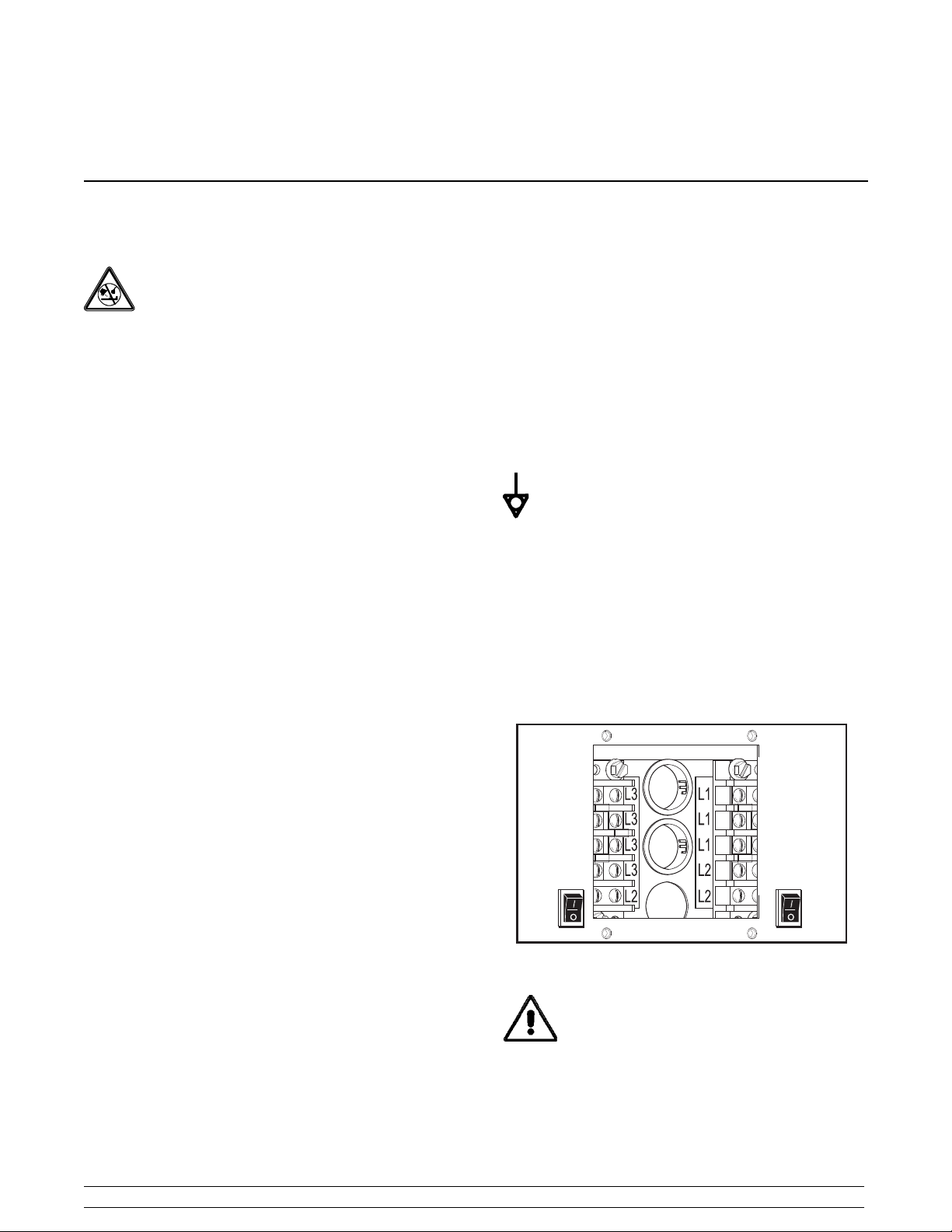
This equipment is provided with a grounding lug
that is to be properly attached to the rear of the frame
by the authorized installer. The installation location is
marked by the equipotential bonding symbol (5021 of
IEC 60417--1) on the removable panel and the frame.
The proper wire size and fused circuit should be
selected according to grill data label information.
Incoming power must be connected to the terminals
with black characters on a white background, as
shown:
14092
Electrical Connections
The QS Series grills have one electrical connection.
Check the data plate on the grill for voltage, cycle,
phase and electrical specifications. The power
connection is located behind the access line cover on
the front of the grill.
In the United States, this equipment is intended to be
installed in accordance with the National Electrical
Code (NEC), ANSI/NFPA 70--1987. The purpose of
the NEC code is the practical safeguarding of persons
and property from hazards arising from the use of
electricity. This code contains provisions considered
necessary for safety. Compliance therewith and
Models QS12 & QS24 To the Installer
THE GRILL DURING A POWER OUTAGE. Grills
require electrical power for operation. In the event of
a prolonged power outage, place the unit in the “OFF”
position.
1
CAUTION: DO NOT ATTEMPT TO USE
Figure 1
050831
Page 6
Ventilation and Clearance
To ensure proper operation of this appliance it must be
installed so that the products of combustion are
efficiently removed. Do not store anything on top of the
grill.
Most service can be performed from the front of the
grill. When inspecting heating elements, the unit must
be disconnected and pulled out of the hood enclosure.
Allow four feet in front of the appliance for this purpose.
Leveling Procedures
Step 1
The leveling adjustment needs to be performed while
the grill is at operating temperature. Remove the cook
surface shroud and release sheet.
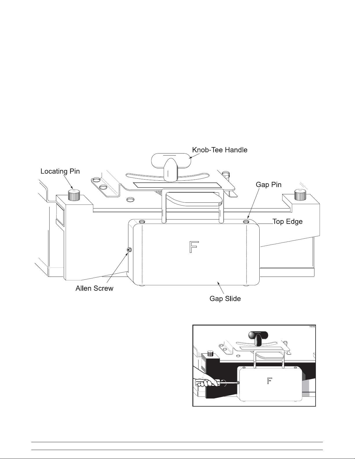
Step 2
To allow adjustment of the gap pins, loosen the two set
screws located on the side of the front and rear gap
slide.
To the Installer
Figure 2
2
Figure 3
Models QS12 & QS24
Page 7
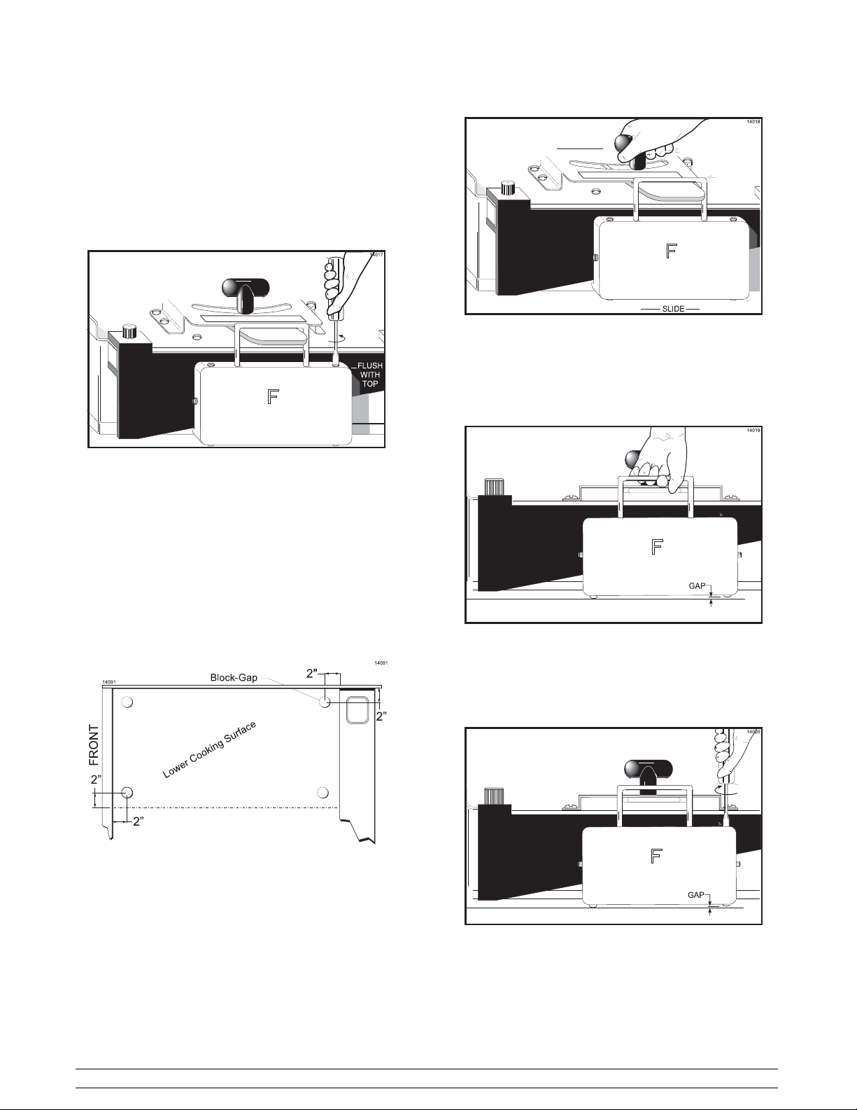
Step 3
Raise or lower both gap pins on the front gap slide until
they are flush with the top edge of the gap slide.
Repeat this step for the rear gap slide. Slide the gap
slide to the right.
Figure 4
Figure 6
Step 6
Wearing proper protection, carefully attempt to raise
the gap slide to evaluate which gap pin is in need of
adjustment.
Step 4
For each cook surface requiring adjustment, place 4
gap blocks on the cook surface, approximately 2”
(51 mm) in from each corner.
Figure 5
Step 5
Lower the cook surface assembly. Loosen and slowly
move the T-handle to the left until the gap pins in the
gap slides touch the cook surface, and tighten the
T-handle.
Figure 7
With the gap slide raised, slowly turn the gap pin
needing adjustment until it makes contact with the
cook surface. Repeat these steps for both gap
slides.
Figure 8
Step 7
Raise the upper cook surface and remove the four gap
blocks.
Models QS12 & QS24 To the Installer
3
Page 8
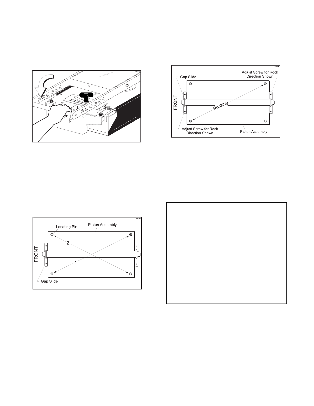
Step 8
Lower the upper cook surface into the COOK position.
Figure 9
Step 10
If the unit rocks, split the adjustment for gap pins
across the uneven corners, as shown in Figure 1 1.
Figure 11
Step 11
After adjusting, verify the unit for stability.
Step 9
Wearing proper protection, attempt to rock the cook
surface assembly. Apply pressure on the locating pins
at opposite corners to each other as shown in Figure
10.
Figure 10
Step 12
If all adjustments on the cook surface are correct, and
no rocking occurs, tighten the two screws located on
the side of the front and rear gap slides to lock all
adjustments from moving.
It is highly recommended that the gap
slides and the gap slide retainers be
removed at least weekly for cleaning these
parts and the cook surface shroud behind
these parts.
These parts are easily removed by
removing the locating pins and holding
both parts, because they are not attached
together, and pulling them from the cook
surface.
Take the gap slides to the sink for
cleaning. (Be sure to re-install the gap
slides as they were removed, i.e., “F”
front.) See Weekly Cleaning Procedures
on page 28.
090401
To the Installer
4
Models QS12 & QS24
Page 9

Section 2 To the Operator
The grill you have purchased has been carefully
engineered and manufactured to provide dependable
operation. This grill is designed to deliver
“cook-to-order” menu items. The two-sided cooking
method increases speed of service and assures safe
product integrity.
The Taylor Grill, when properly operated and
maintained, will produce a consistent quality product.
Like all mechanical products, this machine will require
cleaning and maintenance. A minimum amount of care
and attention is necessary if the operating procedures
in this manual are followed closely.
This Operator’s Manual should be read before
operating or performing any maintenance on your
equipment.
It is strongly recommended that all personnel
responsible for the equipment’s operation and
cleaning, review these procedures for proper training
and assurance that no misunderstandings exist.
In the event that you require technical assistance,
please contact your local authorized Taylor Distributor.
If the crossed out wheeled bin symbol is
affixed to this product, it signifies that this product is
compliant with the EU Directive as well as other similar
legislation in effect after August 13, 2005. Therefore,
it must be collected separately after its use is
completed, and cannot be disposed as unsorted
municipal waste.
The user is responsible for returning the product to the
appropriate collection facility,as specified by your local
code.
For additional information regarding applicable local
laws, please contact the municipal facility and/or local
distributor.
050831
Models QS12 & QS24 To the Operator
5
Page 10
Section 3 Safety
We at Taylor are deeply concerned about the safety of
the operator when he or she comes in contact with the
grill and its parts. Taylor has gone to extreme efforts to
design and manufacture built-in safety features to
protect both you and the service technician. As an
example, warning labels have been attachedto the grill
to further point out safety precautions to the operator.
To Operate Safely:
3” (76 mm) from all combustible materials
(0” to non--combustible materials).
Failure to comply could result in a fire hazard.
Failure to comply may result in personal injury or
equipment damage.
Grill clearance must be maintained at least
This grill must be placed on a level surface.
DO NOT operate the grill without reading this
operator’s manual. This manual should be kept in a
safe place for future reference.
This equipment is provided with a grounding lug
that is to be properly attached to the rear of the frame
by the authorized installer. The installation location is
marked by the equipotential bonding symbol (5021 of
IEC 60417--1) on the removable panel and the frame.
S DO NOT operate the grill unless it is
properly grounded.
S DO NOT use the cord if it is frayed.
S DO NOT attempt any repairs unless the
power supply to the grill has been
disconnected.
S DO NOT operate the grill unless all service
panels are restrained with screws.
S Stationary appliances which are not
equipped with a power cord and a plug or
other device to disconnect the appliance
from the power source must have an
all--pole disconnecting device with a contact
gap of at least 3 mm installed in the external
installation.
Failure to follow these instructions may result in
electrocution. Contact your local Taylor Distributor for
authorized service.
DO NOT use a water jet to clean or rinse the
grill. Failure to follow this instruction may result in the
following:
S serious electrical shock
S burns from hot steam
S liquid collecting inside the grill and
destroying electrical components.
S DO NOT prepare or remove product without
proper equipment.
S DO NOT allow untrained personnel to
operate this grill.
S USE EXTREME CAUTION when cleaning
the grill.
Failure to follow these instructions may result in severe
burns from high temperatures.
Taylor recommends Sizzler Grill Bun and
Toaster Cleaner, a Kay Chemicalr product. Sizzler
is an alkaline detergent and is not environmentally
harmful. Take caution to protect eyes, lungs, and all
parts of the body from potential harm. See the Kay
Chemicalr MSDS for further details.
070116
Safety
6
Models QS12 & QS24
Page 11

DO NOT slide the grill with the legs attached. Failure
to follow this instruction may damage the grill.
DO NOT obstruct air intake and discharge openings:
4” (102 mm) minimum air space on the bottom and 3”
(76 mm) at the rear of the unit. Failure to comply will
affect grill performance and may cause component
damage.
NOISE LEVEL: Airborne noise emission does not
exceed 70 dB(A) when measured at a distance of 1.0
meter from the surface of the machine and at a height
of 1.6 meters from the floor.
Models QS12 & QS24 Safety
7
Page 12
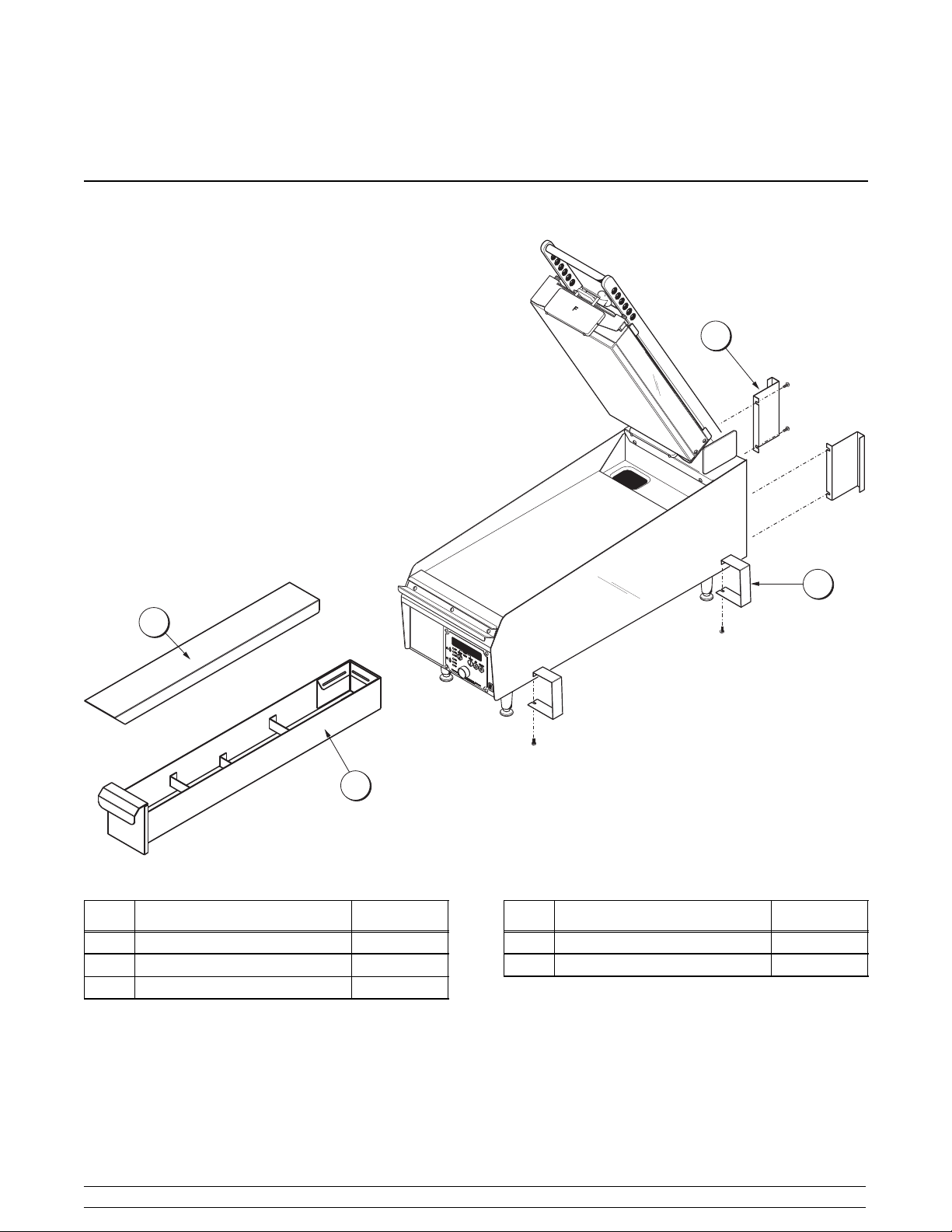
Section 4 Operator Parts Identification
QS12
1
2
4
3
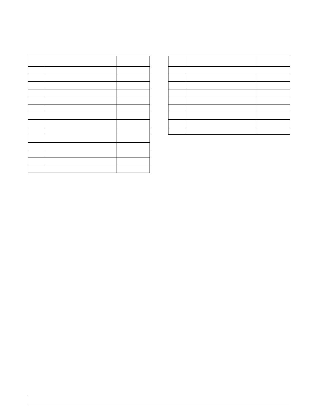
ITEM DESCRIPTION PART NO.
1 STANDOFF-REAR 079288
2 STANDOFF-FRONT 079289
3 TRAY A. - GREASE X79940-SER
O
N
O
F
F
Figure 12
ITEM DESCRIPTION PART NO.
4 COVER-TOP 079969
* CLEANER-SIZZLE 079896
*NOT SHOWN
071102
Operator Parts Identification
8
Models QS12 & QS24
Page 13
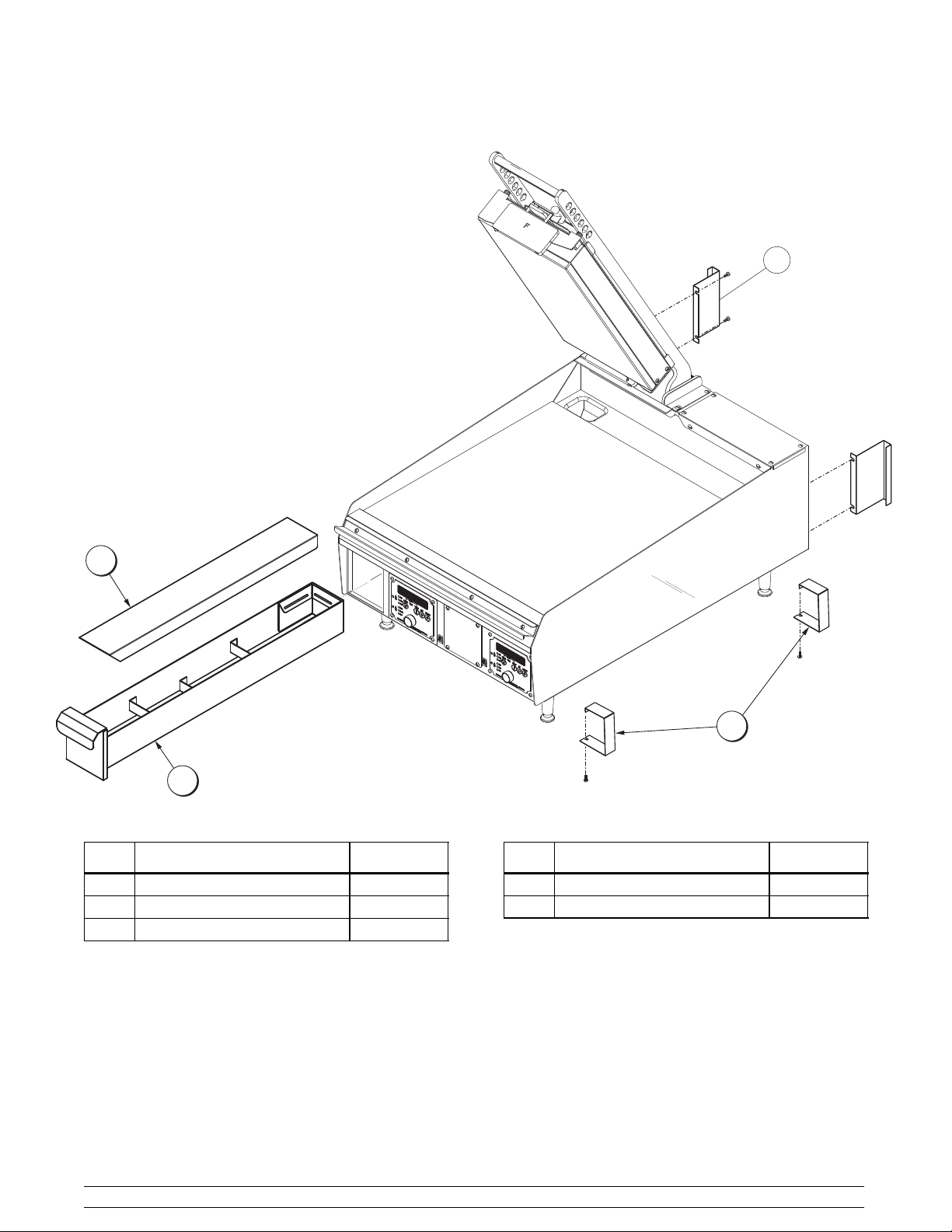
QS24
2
4
1
ITEM DESCRIPTION PART NO.
1 TRAY A.--GREASE X79940--SER
2 COVER--TOP 079969
3 STANDOFF--FRONT 079289
ON
OFF
ON
OFF
Figure 13
3
ITEM DESCRIPTION PART NO.
4 STANDOFF--REAR 079288
* CLEANER--SIZZLE 079896
*NOT SHOWN
071102
Models QS12 & QS24 Operator Parts Identification
9
Page 14
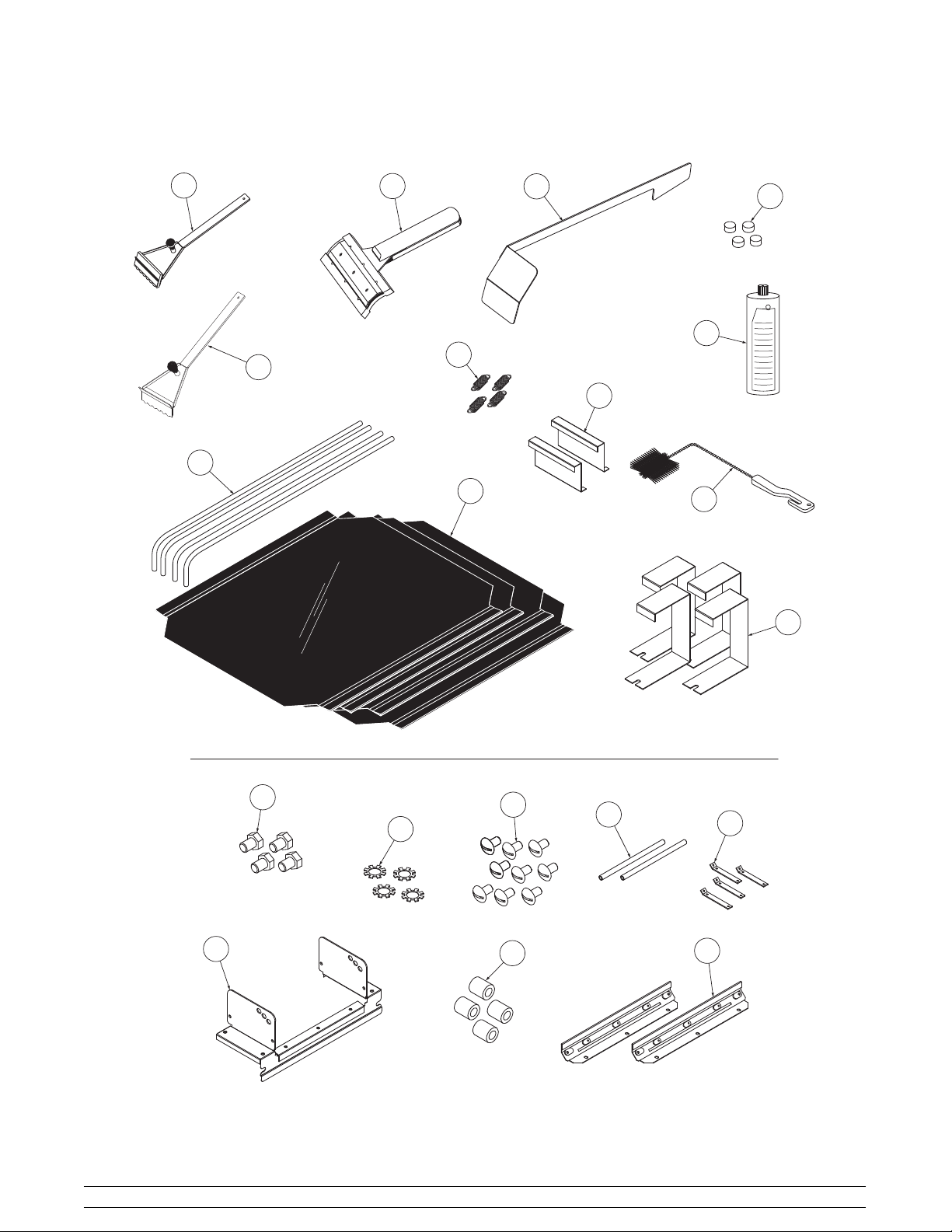
QS12 Accessories
1
3
4
9
S
I
Z
E
Z
L
10
7
2
8
5
6
11
12
13
20
071102
Operator Parts Identification
14
Figure 14
10
15
19
16
17
18
Models QS12 & QS24
Page 15
QS12 Accessories -- Parts Identificatio n
ITEM DESCRIPTION PART NO.
1 SCRAPER A.-GROOVE X79246
2 SCRAPER A.-GROOVE X79668
3 SCRAPER-TEFLON WIPER 075887
4 SCRAPER-TROUGH 079726
5 BAR-RELEASE SHEET 079930
6 SHEET-SEAMED RELEASE 078804
7 SPRING-.438OD X .046 X 1.75 079704
8 STANDOFF-REAR 079288
9 BLOCK-GAGE PLATEN KIT 079912
10 CLEANER-SIZZLE 1 QT 545A 079895
11 BRUSH-.625 X 1.500 074166
12 STANDOFF-FRONT 079289
* CARD-CHECKOUT-GRILL GM 049990
* GUIDE-CHECK OUT-QS 051934
ITEM DESCRIPTION PART NO.
ITEMS 13-20 ARE INCLUDED IN X79689 KIT
13 SCREW-3/8-16X1/2 HEX HEAD 001081
14 WASHER-3/8 EXTERNAL 001087
15 SCREW-10-32X3/8SLTD 024298
16 BAR-STOP 079673
17 BAR-REAR-COVER SUPPORT 079855
18 GUARD A.-FRONT X79426-SP
19 SLEEVE-STOP BAR 079688
20 COVER A.-REAR X79674
*NOT SHOWN
Models QS12 & QS24 Operator Parts Identification
11
Page 16

QS24 Accessories
1
3
4
9
2
10
S
I
Z
E
Z
L
7
8
5
6
11
15
12
13
14
Figure 15
071102
Operator Parts Identification
12
Models QS12 & QS24
Page 17

QS24 Accessories -- Parts Identificatio n
ITEM DESCRIPTION PART NO.
1 SCRAPER A.-GROOVE X79246
2 SCRAPER A.-GROOVE X79668
3 SCRAPER-TEFLON WIPER
4 SCRAPER-TROUGH 079726
5 BAR-RELEASE SHEET 079930
6 SHEET-SEAMED RELEASE 078804
7 SPRING-.438OD X .046 X 1.75 079704
8 STANDOFF-REAR 079288
9 BLOCK-GAGE PLATEN KIT 079912
75887
ITEM DESCRIPTION PART NO.
10 CLEANER-SIZZLE 1 QT 545A 079895
11 BRUSH-.625 X 1.500 074166
12 SCREW-10-32X3/8SLTD 024298
13 BAR-REAR-COVER SUPPORT 079855
14 GUARD A.-FRONT X79426-SP
15 COVER A.-REAR X74332
* CARD-CHECKOUT-GRILL GM 049990
* GUIDE-CHECK OUT-QS 051934
* INSTRUCTION-GRILLOPER 053656-INS
*NOT SHOWN
Models QS12 & QS24 Operator Parts Identification
13
Page 18

Section 5 Important: To the Operator
3
UF
MENU
UM
UR
4
LR
LM
LF
MANUFACTURED BY THE TAYLOR COMPANY
ROCKTON, ILLINOIS U.S.A.
5
ITEM DESCRIPTION
1 Power Switch
2 Keypads
3 LED Display
4 Indicator Lights
5 Timer Button
Power Switch (Rocker)
When placed in the “ON” position, the power switch
allows control panel operation for the applicable side
of the grill. The power switches are located on the front
panel.
EXIT
TIME
TEMP
UP
DOWN
1
I
0
2
Release Material (units with upper
cook surfaces only)
Step 1
Lay the release material sheet on the lower plate and
carefully lower the upper cook surface.
Step 2
Starting with the spring side, slide the straight end of
the release material rod through the front spring,
continue through the hemmed end of the release
sheet, and through the rear spring.
Indicator Light
The lights on the front panel indicate when the heaters
are operating.
Heating Zones
Each side (zone) of the grill is equipped with three
independent heating elements. The independent
elements assure even temperatures and quick
temperature recovery.
Timer Button
Used to start and stop the cook timer.
071102
Important: To the Operator
Step 3
Insert the second rod through the opposite hemmed
side of the release material sheet. Grasp both ends of
the rod, pull the release material up and around the
non-spring side of the upper cook surface and attach
the rod ends to the retaining clips. Turn the rods so that
the hooked end is facing downward.
Step 4
Raise the upper cook surface and assure that the
release material sheet fits evenly and snugly on the
upper cook surface. Rotate the release material sheet
on an every other day basis.
14
Models QS12 & QS24
Page 19

Temperature Controls
Operating Screen and Controls
The Model QS12 is equipped with one temperature
control and the Model QS24 is equipped with two
individual temperature controls. They control both the
upper and the lower temperatures. The lower cook
surface temperatures can be set manually from 150_
- 400_F(65_ - 204_C). The upper cook surface
temperatures can be set manually from 150_ - 425_F
(65_ - 219_C). The left and right sides (zones) of the
Model QS24 grill operate independently.
Control Board
This unit is equipped with a microprocessor control,
programmable by the operator.
Keypad and Display
Located on the front panel, beneath each cook zone,
is an alpha-numeric LED display and a group of keys
used for operating, programming, and servicing the
grill and its microprocessor control.
The keys are illustrated with icons, descriptive of their
functions, and referred to in these instructions as
follows:
The VERSION SCREEN is viewed when a grill is
powered for normal operation. It indicates the version
of software the microprocessor is using.
VER 1.01B
Note: If the grill is not equipped with the upper cook
surface option, the words “NO PLTN” will appear on
the display for two seconds before the version screen
appears.
The MEMORY INITIALIZATION SCREEN appears if
the grill has never been used or in the rare event that
set-up parameter memory has been lost.
MEM INIT
=MENU
=TEMP
= UP ARROW
= DOWN ARROW
The display is a visual message center for the user,
operator (maintenance personnel or manager), and
the service technician.
When this screen appears on the display, the
parameters previously programmed by the operator
will revert back to the factory default values. Pressing
the MENU key will advance the display to the
VERSION screen.
Factory defaults:
Upper 400_FTM130
Lower 325_FTM20
If set-up parameter memory is lost, programmed
names will revert back to the “ITEM” messages.
After the VERSION SCREEN is displayed and a key
is pressed, the grill will enter the COOK mode of
operation.
Models QS12 & QS24 Important: To the Operator
15
Page 20

Cook Temperatures
Step 1
To set cook temperatures, press the up or down arrow
to select the item to be changed. Press and hold the
temperature key for five seconds. After releasing the
key, the message “SU1” and the current set
temperature will be displayed. (See example below .)
SU1 400 F
(Set upper item 1)
Step 2
Use the arrow keys to adjust the desired cook
temperature setting for the upper cook surface.
Temperatures may be set for 150_F to 425_F(66_to
218_C).
Step 3
Press the MENU key and the message “SL1” and the
current temperature will appear on the display. (See
example below.)
middle of the cook cycle. Timer two should then be
programmed for 15 seconds. Once the cook cycle
begins, a tone will sound 15 seconds after the first
timer starts, alerting the operator to season the
product. Press the timer key to stop the tone. The first
timer will continue to measure the full 30 second cook
cycle.
A tone will sound 5 seconds before the time elapses,
and will continue to sound until the timer key has been
pressed. (This timer can be adjusted from 0 -- 10
seconds.)
Note: The factory default settings are 30 seconds for
the first (cook cycle) timer, and 0 seconds for the
second (alert) timer. The timers can be set from 0 to
3,600 seconds. The second timer cannot be
programmed for a longer time setting than the first
timer.
To adjust the timers, press the up or down arrow to
select the item to be changed. Press and hold the time
key for five seconds. Release the key and the
message “TM1” will appear next to the current time
setting. (See the example below.)
SL1 325 F
(Set lower item 1)
Step 4
Use the arrow keys to adjust the desired cook
temperatures for the lower cook surface. The range for
the lower cook surface temperatures is 150_Fto
400_F(66_to 204_C).
Press the MENU key again to return to the selected
item display.
Cook Timers
Each item selection has two programmable cook
timers. The first timer is the cook cycle timer. This timer
measures the amount of time the product should be
cooked.
The second timer is an alert timer. This timer can be
set to alert the operator to add seasonings, to turn the
product, or to start warming buns for the cooked
product.
For example, item one has been programmed to cook
for 30 seconds. The operator wishes to add salt in the
TM1 30
Step 1
Press the UP or DOWN arrows to adjust the time
setting for the total cook cycle.
Step 2
Once the desired cook time has been set, press the
MENU key and the message “TM2” will appear next to
the current time setting. (See the example below.)
TM2 0
Step 3
Press the UP or DOWN arrows to adjust the time
setting for the alert timer (timer 2).
Step 4
Once the desired alert timer has been set, press the
MENU key to return to the selected item display.
Repeat this step for each item.
080429
Important: To the Operator
16
Models QS12 & QS24
Page 21

Fault Screen
Maintenance Menu
If the grill experiences a system failure, a fault
message will appear on the display, and a tone will
sound.
FLT HTUM
An example of the FAULT SCREEN is illustrated in the
previous figure. The screen appears when the
controller has detected a fault in the system. The code
letters “FLT” is an abbreviation for “fault”. The next set
of code letters indicate the type of fault and the zone
affected. Following is a list of possible codes that may
appear on the screen:
HTUF High Temperature Upper Front zone exceeded
HTUM High T emperature Upper Mid zone exceeded
The Maintenance Menu provides five screens to allow
managers and service technicians to monitor grill
performance.
To enter the Maintenance Menu while any item is
displayed, press and hold the MENU key for
approximately 5 seconds and release. The following
screen will appear on the display.
CODE 0000
Press TIME until the first digit is “5”.
Example: CODE 5000.
Press TEMP until the next digit is “3”.
Example: CODE 5300.
Press the UP Arrow until the next digit is “7”.
Example: CODE 5370.
Press the DOWN Arrow until the last digit is “6”.
Example: CODE 5376.
Press the MENU key to accept the access code and
the following screen will appear:
HTUR High Temperature Upper Rear zone exceeded
HTLF High Temperature Lower Front zone exceeded
HTLM High T emperature Lower Mid zone exceeded
HTLR High Temperature Lower Rear zone exceeded
TCUF Upper Front thermocouple fault
TCUM Upper Mid thermocouple fault
TCUR Upper Rear thermocouple fault
TCLF Lower Front thermocouple fault
TCLM Lower Mid thermocouple fault
TCLR Lower Rear thermocouple fault
The user must press the MENU and TEMP keys to
acknowledge the fault. The fault description and item
name will appear alternately on the display. The zone
that has the fault will shut down while the rest of the grill
will be operational. (Refer to the Fault Screen
information in the Service Manual, Controls and
Systems Section.)
CALIBRAT
Note: If an incorrect code is entered, the display will
return to the cook screens.
Step 1
Press the MENU key to enter the calibrate mode and
the following message will appear on the screen.
UFXX X F
There are three lower heating elements in each cook
zone and three heating elements in the upper cook
surface (if applicable). The calibrating screens allow
calibration of each independent heating element.
Calibrating verifies proper temperatures of heating
elements.
Models QS12 & QS24 Important: To the Operator
17
Page 22

Note: A calibrated pyrometer must be used for
calibration.
Note: Calibration is allowed only when the item1
temperatures are within 50_ F(28_ C) of the set point.
Step 2
Place the pyrometer disc on the upper front heating
element of the grill. Using the arrow keys, enter the
temperature reflected on the pyrometer for the upper,
front heating element.
Note: The indicating lights should be lit when
calibration adjustments are made.
Figure 16
Step 3
Press the MENU key to display the calibration screen
for the upper middle heating element. Place the
pyrometer on the upper middle heating element. Using
the arrow keys, enter the temperature reflected on the
pyrometer for the middle of the upper heating element.
Step 1
Press the MENU key to display the current
temperature scale:
SCALE F or C
Step 2
If Fahrenheit is the desired temperature scale, press
the MENU key while SCALE F is displayed. If Celsius
is desired, press the UP arrow to display SCALE C.
Step 3
Press the MENU key to accept the scale and return to
the SCALE message.
Step 4
If desired, the names of specific products can be
programmed to appear on the display instead of ITEM
numbers. While at the SCALE message display, press
theUParrowtodisplaytheNAMES message.
NAMES
Step 4
Repeat this procedure for the remaining upper rear,
and lower heating elements. When the last zone has
been calibrated, press the MENU key to return to the
CALIBRAT screen.
Step 5
Press the UP arrow to display the “SCALE” message.
SCALE
Note: The CALIBRAT screen is the base
maintenance screen. All other maintenance
functions are accessible through the CALIBRAT
screen.
Important: To the Operator
Step 5
While at the NAMES message display, press the
MENU key and the message “NAME1” will appear on
the display. This message indicates that the operator
can program a specific product name to appear for the
first item on the menu.
NAME1
18
Models QS12 & QS24
Page 23

Step 6
Press the MENU key again, and the message “ITM1”
will appear on the display. The letter “I” will be flashing
above the cursor.
ITM1
Step 9
Use the UP arrow key to display the message
“NAME2.”
Repeat Steps 6-9 until all desired item names have
been entered.
Step 10
After entering the desired characters in the NAMES
screens, the control will return to “NAME1”.
Step 7
Using the UP and DOWN arrow keys, enter the
desired letter (A - Z) or number (0 - 9) ( -- _ ). Once the
character letter is entered, press the MENU key to
move the cursor to the next position. Up to four
characters may be entered.
POM1
PORK
Step 8
After the last character has been entered, press the
MENU key to return to the message “NAME1”.
Press the DOWN arrow to display “NAMES”.
Step 11
Press the UP arrow to display “LANGUAGE”, and
press the MENU key to display “ENGLISH”.
Press the MENU key to return to the “LANGUAGE”
display.
Step 12
Press the UP arrow to display “MONITOR”.
Press the MENU key to display “UF XXX F” to monitor
the upper front temperature.
Step 13
Continue to press the UP arrow to monitor the
remaining five zones.
Step 14
Press the UP arrow to display “CANCEL”, and press
the MENU key to display “MONITOR”.
Press the MENU and TEMP keys at the same time to
return to the main cook screen.
Models QS12 & QS24 Important: To the Operator
19
Page 24

Maintenance Menu Flowchart
Important: To the Operator
20
Models QS12 & QS24
Page 25

Section 6 Operating Procedures
The Model QS12 has one, 12” (305 mm) lower cook
surface and the option of an 11” (279 mm) upper cook
surface. The Model QS24 has two, 12” (305 mm) lower
cook surfaces and the option of one 11” (279 mm)
upper cook surface or two 1 1” (279 mm) upper cook
surfaces. The QS24 is also available with a grooved
lower cook surface for product sear. The two-sided
cooking concept ensures quick, even cooking of both
sides of products placed on the lower surface.
We begin our instructions with the opening
procedures, assuming product set-up procedures
(outlined in the “Important to the Operator” section of
this manual) are complete.
Opening Procedures
Before operating the grill, a release material sheet
must be installed on the upper cook surface.
CAUTION: Make sure the grill is cool
before attempting to install or remove release
material.
Perform the following steps for installing release
material:
Step 1
Lay the release material sheet on the lower plate and
carefully lower the upper cook surface.
Step 2
Starting with the spring side, slide the straight end of
the release material rod through the front spring,
continue through the hemmed end of the release
sheet, and through the rear spring.
Figure 18
Step 3
Insert the second rod through the opposite hemmed
side of the release material sheet. Grasp both ends of
the rod, pull the release material up and around the
non-spring side of the upper cook surface and attach
the rod ends to the retaining clips. Turn the rods so that
the hooked end is facing downward.
Figure 17
Models QS12 & QS24 Operating Procedures
21
Figure 19
Page 26

Step 4
Raise the upper cook surface and assure that the
release material sheet fits evenly and snugly on the
upper cook surface. Rotate the release material sheet
on an every other day basis.
Note: It is not necessary to replace the release
material sheet if small pinholes develop.
Operating Procedures
Figure 20
22
Models QS12 & QS24
Page 27

CAUTION: Release material sheets must be
replaced if:
S Release material is torn.
S Release material substance is worn from the
release material sheet.
S Product sticks to the release material.
Cooking Procedures
Step 1
Make sure the release material is installed.
Step 2
Place the power switches in the ON position. The
screen will scroll through information messages and
then advance to the first cook screen.
Step 4
Allow the grill to heat for approximately 15 minutes or
until all indicating lights are no longer illuminated.
DO NOT begin cooking until the grill has reached set
temperature. If the grill is not at cook temperature, the
display will alternate between the item number and the
words, “TOO COOL”. If the grill is too hot to cook the
selected product, the display will alternate between the
item number and the words “TOO HOT”. When the
words “TOO COOL” or “TOO HOT” stop appearing on
the display, and all indicator lights have cycled off, the
grill is ready to cook product.
Step 5
To adjust the gap between the upper cook surface and
lower cook surface, loosen the “T” handle and slide the
gap adjusting bar to the right for a smaller gap or to the
left for a larger gap.
Figure 21
Note: If there is no upper cook surface, the words
“NO CLAM” will appear on the screen prior to the
software version number.
Step 3
Press the UP arrow until the desired item number
appears on the display.
14293
UF
UM
UR
LR
LM
LF
MANUFACTURED BY THE TAYLOR COMPANY
EXIT
TIME
TEMP
MENU
ROCKTON, ILLINOIS U.S.A.
UP
DOWN
I
0
Figure 22
Figure 23
Step 6
While the upper cook surface is in the raised position,
place the product on the lower cook surface. Lower the
upper cook surface, and press the TIME key. A tone
will sound for two seconds, alerting the operator that
the cook cycle has been initiated.
Figure 24
Models QS12 & QS24 Operating Procedures
23
Page 28

CAUTION: The grill is hot. To prevent
personalinjury, always use the handle to lowerthe
upper cook surface.
Step 7
If the timer is programmed, press the large red TIMER
button. A tone will sound for two seconds, alerting the
operator that the COOK cycle has been initiated. The
timer will count down in seconds. When five seconds
are left in the cook time, a tone will sound to alert the
operator that product is ready for serving. Raise the
upper cook surface. (If a second timer is entered,
subtract that amount from the total time and a tone will
sound. Press the large red TIMER button to stop the
tone and the control will continue to count down.)
14294
UF
UM
UR
LR
LM
LF
MANUFACTURED BY THE TAYLOR COMPANY
EXIT
TIME
TEMP
MENU
ROCKTON, ILLINOIS U.S.A.
UP
DOWN
I
0
Cleaning Between Product Runs
After each run of product, the grill must be cleaned to
ensure proper cooking.
Step 1
Using a grill scraper, scrape residue from the lower
cook surface (scrape from front to back only).
Figure 26
Step 2
Use a rubber wiper squeegee to clean release material
on the upper cook surface. Hold the handle at a slight
upward angle with wiper end facing downward. Wipe
the material using a downward motion. DO NOT use
extreme pressure or force. Improper procedures will
tear or crease the release material.
Figure 25
To cancel the tone, press the large red TIMER button.
Step 8
Carefully remove product with a safe cooking utensil
in the same order the product placed on the grill.
071102
Operating Procedures
Figure 27
Note: DO NOT use a scraper, sharp utensils, or
abrasives for cleaning the upper cook surface.
24
Models QS12 & QS24
Page 29

Step 3
Using the rubber wiper squeegee, push the grease to
the rear of the lower surface into the grease trough. DO
NOT use the grill scraper for this step.
Step 4
When necessary, use a grill cloth to clean the back
splash shield and the bullnose areas.
Step 5
Repeat Steps 1 through 4 for other side of the grill
(QS24 only).
Note: Whenever the grill is idle and product is not
being cooked, keep the upper cook surface in the
raised position.
When necessary, use the trough scraper to clean the
rear grease trough. If a buildup of carbon is starting in
the grease chute, use the hook end of the trough
scraper to push the carbon down into the grease tray.
Periodically, check the grease drawer for excess
grease and empty it as needed.
Figure 29
Step 5
Carefully remove the grease tray partition. Take it to
the sink for cleaning.
Figure 30
Figure 28
Cleaning the Grease Tray Partition
Occasionally, the grease tray partition must be
cleaned.
Step 1
Place the power switch in the OFF position.
Step 2
Carefully unplug the unit from the wall receptacle.
Step 3
Remove the grease tray.
Step 4
Remove the four screws that secure the grease tray
partition.
Models QS12 & QS24 Operating Procedures
Note: For installation of the grease tray partition,
carefully reverse the above steps.
It is highly recommended that the gap
slides and the gap slide retainers be
removed at least weekly for cleaning these
parts and the cook surface shroud behind
these parts.
These parts are easily removed by
removing the locating pins and holding
both parts, because they are not attached
together, and pulling them from the cook
surface.
Take the gap slides to the sink for
cleaning. (Be sure to re-install the gap
slides as they were removed, i.e., “F”
front.) See Weekly Cleaning Procedures
on page 28.
090401
25
Page 30

Closing Procedures
Step 1
Raise the upper cook surface to the “raised” position.
Step 2
Turn the power switches to the OFF position.
Step 7
Dampen the gap slide brush with an approved, full
strength cleaner/degreaser (i.e., Sizzler Grill Bun and
Toast Cleaner, a Kay Chemicalr product).
Step 8
Clean the shroud by brushing between the platen
shroud and the gap slides.
Figure 31
Step 3
Wipe the release material sheet thoroughly while still
attached to the upper cook surface, using the rubber
wiper squeegee.
CAUTION: The upper cook surface and
release material sheets are very hot. To prevent
burn injuries, wear protective gloves and use
extreme care when performing this procedure.
Step 4
Remove the release material sheet from the upper
cook surface by pulling the release rods from the
release material sheet. Temporarily place the release
material sheet on a clean, flat surface for further
cleaning. DO NOT fold or crease the material or lay it
on sharp objects.
Step 5
Take the release material rods to the sink for cleaning.
Step 6
Clean the upper cook surface(s) with the special
rubber squeegee.
Note: DO NOT use metal scrapers, abrasive pads,
screens or wire brushes to clean the upper cook
surface.
Figure 32
Step 9
Repeat Steps 7 and 8 with warm water.
CAUTION: Protect eyes, lungs, and all
parts of the body from potential harm when using
any chemical cleaner.
Step 10
Starting from the top of the upper cook surface, spray
full strength cleaner/degreaser (i.e., Sizzler Grill Bun
and Toaster Cleaner, a Kay Chemicalr product.) from
6” (152 mm) away. (Use a cleaner that will not
damagealuminum.)Spray one ounce of cleaner over
each upper cook surface and two ounces on the lower
cook surface. Let the cleaner soak for 3 -- 5 minutes.
Note: One ounce of cleaner equals approximately
thirty squirts.
Step 11
Starting from the top of the upper cook surface and the
rear of the lower cook surface, rinse both surfaces with
a mist of water from a spray bottle.
CAUTION: Use care not to spray water or
cleaner/degreaser on any part of the grill, other
than the cook surfaces. Improper procedures will
cause permanent electrical and mechanical
damage to internal parts.
Operating Procedures
26
Models QS12 & QS24
Page 31

IMPORTANT: Do not use a jet of water to
clean or rinse the grill.
Step 12
Use the rubber wiper squeegee to remove excess
liquid from the upper and lower surfaces.
IMPORTANT! Do not scrape the upper surface
with metal utensils.It is aluminum and will scratch
very easily.
Step 13
Repeat Steps 10 and 11if necessary, but apply cleaner
only to soiled areas.
Step 14
Remove any small carbon spots with the rubber
squeegee.
Step 15
Using a damp cloth, wipe down all exterior stainless
steel of the upper cook surface (especially behind the
rear of the upper cook surface, next to arm assembly).
Note: Grills should be removed from cooking alcoves
in order to clean the rear section of the upper cook
surface.
CAUTION:
S Never use cold water or ice to cool the
upper cook surface or lower grill plate.
S Never use grill screens on the upper cook
surface or lower grill plate.
S Never use any other abrasives or cleaners
other than approved food service cleaners
and degreasers.
S Never spray excessive amounts of water on
the grill.
S Never pour or spray liquid of any type on
the top of the upper cook surface.
Step 21
Place release material sheet(s) on the warm lower grill
plate and thoroughly wipe down both sides with a
clean, damp grill cloth.
Step 16
Clean lower grill by pouring warm water carefully on
the surface while brushing with sturdy brush.
CAUTION: Wear rubber gloves to avoid
hot steam.
Step 17
Continue to add water and brush the surface until the
grill is cool enough to squeegee dry.
Step 18
Wipe the cook surface(s) twice with a clean, damp
towel.
Step 19
Wipe all areas of the grill with a clean, damp towel.
Step 20
Wipe all exterior stainless steel panels around the
entire grill.
CAUTION:
S Never attempt to clean release material
sheets on a cold surface.
S Never use a hot hose for cleaning release
material, or soak release material sheets in
liquid.
S Never fold, crease or touch release material
sheets with sharp objects.
S Never allow the grill scraper or abrasive
cleaning materials to come in contact with
release material sheets.
Step 22
Apply a light coat of shortening to the entire lower grill
plate.
Models QS12 & QS24 Operating Procedures
27
Page 32

Weekly Cleaning Procedures
Step 1
Loosen, but do not remove the four locating pins that
attach both sets of Gap Slide Retainers. One set is
located at the front and one set is located at the rear
of the upper platen.
Step 2
Lift the upper platen to the raised position. Remove
the four locating pins on both ends of the platen.
Step 3
Removeboth setsof the GapSlideRetainers andGap
Slides. Take them to the sink for washing, rinsing and
sanitizing. Wipe dry with a clean, sanitized towel.
Step 4
Re-install the Gap Slide Retainers and the GapSlides
in their original locations.
Note: The front Gap Slide set will be marked with an
(F ) todesignate thefrontlocation. The rearsetwillnot
be marked.
090401
Operating Procedures
28
Models QS12 & QS24
Page 33

Section 7 Troubleshooting Guide
PROBLEM PROBABLE CAUSE REMEDY
1. Grill will not heat. a. Power cord is not connected. a. Check power connection.
b. Circuit breaker is tripped. b. Reset the circuit breaker.
2. One heat zone will not heat.
(Indicator light is not on,
display flashing “TOO COOL”.)
3. One heat zone will not heat.
(Indicator light is on, display
flashing “TOO COOL”.)
c. Power switch is in the OFF
position.
d. Power switch is faulty. d. Contact a service technician.
e. Faulty relay or relay board. e. Contact a service technician
a. Control is not set correctly. a. Check temperature setting.
b. Faulty relay or relay board b. Contact a service technician.
c. Unit displays a fault. c. Clear the fault. If action is
d. Faulty thermocouple. d. Contact a service technician.
a. Heater is faulty . a. Contact a service technician.
b. Thermocouple is faulty. b. Contact a service technician.
c. Thermo overload is faulty. c. Contact a service technician.
d. Relay or relay board is faulty. d. Contact a service technician.
e. Unit displays a fault. e. Clear the fault. If action is
c. Place the power switch in the
ON position.
ineffective, contact a service
technician.
ineffective, contact a service
technician.
4. One heat zone is overheating.
(Display is flashing “TOO
HOT”.)
5. Upper cook surface will not
stay in the raised position.
Models QS12 & QS24 Troubleshooting Guide
a. Thermocouple is faulty. a. Contact a service technician.
b. Relay or relay board is faulty. b. Contact a service technician
c. Unit displays a fault. c. Clear the fault. If action is
ineffective, contact a service
technician.
a. Defective gas filled cylinder(s). a. Contact a service technician.
29
Page 34

PROBLEM PROBABLE CAUSE REMEDY
6. Product is under-cooked,
overcooked, or cooking
unevenly.
7. Control is displaying fault. a. Refer to “fault screens”,
8. Grease drips from under the
grease drawer.
a. Release material sheet is
worn.
b. Incorrect cooking time. b. Adjust cook time accordingly.
c. Incorrect temperature setting. c. Adjust temperature setting.
d. Incorrect gap setting. d. Adjust gap.
e. Heat zone not heating. e. Contact service technician.
f. Upper cook surface has carbon
build-up.
g. Incorrect temperature
calibration.
h. Cook surfaces are not parallel. h. Call a service technician to
i. Incorrect item selected. i. Select proper item.
page 17.
a. Grease tray is full. a. Empty the grease tray.
a. Replace the release material
sheet.
f. Closing procedures must be
followed to remove carbon
build-up.
g. Calibrate the grill accordingly.
level the grill or refer to leveling
procedure in front of manual.
a. Clear the fault. If action is
ineffective, contact service
technician.
9. The grease drawer will not
close.
a. Product has built up in back of
grease partition.
a. Refer to “Cleaning the Grease
Tray Partition” instructions.
Troubleshooting Guide
30
Models QS12 & QS24
Page 35

Section 8 Wa rranty Explanation
Parts
Class 103 Parts
The warranty for new equipment is one year, with a
replacement parts warranty of three months.
Class 000 Parts
Wear items -- no warranty.
Class 212 Parts
The warranty for new equipment parts is two years,
with a replacement parts warranty of 12 months. This
includes the microprocessor control, relays, and the
upper cook surface (aluminum casting and shroud).
Labor
The Taylor warranty is valid only if the required service
work is performed by an authorized T aylor technician.
For more details, see the warranty/checkout card.
Contact your local Taylor Distributor regarding
Extended Service Contract options.
Models QS12 & QS24 Warranty Explanation
31
Page 36

Section 9 Parts List
143
UPDATE
REMARKS PARTS
FOR SERVICE -- USE X74036--SER
WARR.
CLASS
QTY.
QS24
QTY.
QS12
NUMBER
DESCRIPTION PART
X79838 1 103 LEFT SIDE -- J8050000/UP (50HZ & 60HZ)
X79839--23R 1 103 RIGHT SIDE -- J8050000/UP (60HZ)
1 2 103
X40788--SER
PCB A . --CONTROL (BASE BOARD) X53319--SER 1 2 212
CHIP-- SOFTWARE (VERSION 1.01)
+BRACKET ”E” RELAY 074040 6 12 103
RELAY--30A--277V--12VDC 074041 6 12 103
STRAP A.GROUNDING *QS24* X74123 1 2 000
CONNECTOR-- MATE LOK 6 CIR--SKT 029248 1 2 103
CONNECTOR-- MATE LOK 6 CIR--SKT 029248 2 4 103
SOCKET-- 084 OD/14-- 2 0 AWG-- STRIP 021625 9 18 103
HARNESS--WIRE (RELAY BOX) 074039 1 2 103
PCB A.--CONTROL X53512--SER 1 2 212
BAR--RELEASE SHEET *QS24* 079930 2 2 103 137
BLOCK--GAGE PLATEN KIT 078095 4 4 103
BLOCK-- TERMINAL--5P SCREW
W/JUMPERS
BLOCK-- TERMINAL--5P SCREW
W/JUMPERS
BLOCK-- TERMINAL--5P SCREW 079045 1 103 LEFT SIDE -- PRIOR TO J8050000
BLOCK-- TERMINAL--5P SCREW 079045--23R 1 103 RIGHT SIDE -- PRIOR TO J8050000
BLOCK-- TERMINAL--6P SCREW 076943 1 103
BOX A. --RELAY *QS12/QS24* (NEW) X74036--SER 1 2 212 J9054573/UP -- 50HZ & 60HZ
+ Available Separately
Parts List Models QS12 & QS24
32
SOCKET-- 084 OD/14-- 2 0 AWG-- STRIP 021625 3 6 103
BOX A. --RELAY *QS12/QS24* (OLD) X79678--SER 1 2 212 USE X74036--SER IN ALL APPLICATIONS 122, 143
HARNESS--WIRE RELAY BOX *QS24* 078616 1 2 103 INTERFACE TO KEY PAD BOX
PCB A.-- CONTROL GRILL X48604--SER 1 2 212 USE X74036-- SER
CHIP-- SOFTWARE *QS24* CONTROL X40863 1 2 103
PCB A . --INTERFACE GRILL X49540--SER 1 2 212 USE X74036--SER
RELAY--SPDT--200/240 VAC 079690 3 6 103 J7100000--J9054572 (for 1800 WATT heater) 122
STRAP A.GROUNDING *QS24* X74123 1 2 000
BOX A. --RELAY -- (OLD) X78757 1 2 212 USE X74036--SER IN ALL APPLICATIONS 143
BOX A. --REMOTE KEY PAD *QS12 & QS24* X78579 1 2 212
BEEPER--WITH WIRE HARNESS *QS 078617 1 2 103
Page 37

UPDATE
REMARKSWARR.
CLASS
QTY.
QS24
X50412--SER PCB. A & X74320-- SER DECAL
QTY.
QS12
PART
NUMBER
DESCRIPTION PARTS
BUMPER--.500 DIA X .090 THK 079499 1 2 000
DECAL-- KEY PAD *QS24* X74320--SER 1 2 000
BUMPER--.500 DIA X .090 THK 079499 1 2 000
FILTER--CORCOM 2VR1 032567 1 2 103 PRIOR TO J9054573 143
GASKET-- BOX A. 074060 1 2 000 J9054573/UP 143
HARNESS--WIRE REMOTE *QS24* 078614 1 2 103
PAD A. --KEY REMOTE *QS24* X78573 1 2 103
PCB A.-- REMOTE GRILL X50412--SER 1 2 212 J6041233/UP
CHIP-- SOFTWARE QSDSP CONTROL X40908 1 2 103
PCB A.-- REMOTE GRILL J6041232/PRIOR MUST UPDATE WITH
SWITCH-- MEMBRANE--5 P OSITION--8”L 044520 1 2 103
BRACKET-- FRONT TRAY *QS12* 079272 1 103
BRACKET-- FRONT TRAY *QS24* 078527 1 103
BRUSH--.625X1.500 QS12/24 074166 1 1 000 J9110000/UP 147
+PIN-- MALE .084”DIA-- MATE-- N--LOK 021624 3 6 103
CLEANER--SIZZLE #545A 079896 1 1 000 CASE OF 6 QUARTS W/SPRAY BOTTLE
CONNECTOR-- MATE LOK 6 CIR--PIN 028594 2 4 103
CORD A.--POWER X79291 1 103
+BUMPER--.500 DIA X .090 THK 079499 1 000
CORD A.--POWER X79877 1 103 GROOVED PLATEN ONLY
COVER A. --PLATEN *QS24* X78798 1 1 103
COVER A. --REAR *QS12* X79444 1 103
COVER A. --REAR *QS24* X74332 1 103 REPLACES X79423
COVER--LINKAGE *QS24* 079441 1 103
CYLINDER-- GAS DUEL SEAL QS24 074313 2 2 103 REPLACES 079215
DECAL A.--KEYPAD QS SERIES X74320 --SER 1 1 000 GREEN (Replaces Old Red Decal -- 078612)
DECAL-- MIN CLEARANCE *QS24* 079061 1 1 000
DECAL-- TERMINAL BLOCK--LEFT 079046--23L 1 000
DECAL-- TERMINAL BLOCK--RIGHT 079046--23R 1 000
DIAGRAM-- WIRING 074063-- 1 1 000 J9054573/UP 143
DIAGRAM-- WIRING 079691-- 1 1 000 J7100000 TO J9054573 122
DIAGRAM-- WIRING 078807-- 1 1 000 PRIOR TO J7100000 122
+ Available Separately
Models QS12 & QS24 Parts List
33
Page 38

UPDATE
REMARKSWARR.
CLASS
BOX
143
ZONES) REPLACE WITH 074178 -- T/C
LOWER FRONT QS, 074179 -- T/C LOWER
MIDDLE QS, 074180 -- T/C LOWER REAR QS
AS REQUIRED OR ALL 3 TO REPLACE
HARNESS.
ZONES) REPLACE WITH 074178 -- T/C
LOWER FRONT QS, 074179 -- T/C LOWER
MIDDLE QS, 074180 -- T/C LOWER REAR QS
AS REQUIRED OR ALL 3 TO REPLACE
HARNESS.
(PRIOR TO J9054573)
QTY.
QS24
QTY.
QS12
PART
NUMBER
DESCRIPTION PARTS
GASKET-- ACCESS COVER 074059 1 000 J9054573/UP 143
078620 1 2 103 POWER SWITCH TO INTERFACE BOARD
+CONNECTOR-- HOUSING 3 PIN 078596 1 2 103
HARNESS-- CONTROL TO REMOTE QS24 078618 1 2 103 CONTROL BOARD TO REMOTE KEY PAD
HARNESS--T/C LOWER *QS12* 079292 1 103 THERMOCOUPLES (6 L OWER COOKING
HARNESS--T/C LOWER *QS24* 078643 1 103 THERMOCOUPLES (6 LOWER COOKING
HARNESS--T/C UPPER #4 078622--4 1 1 103 THERMOCOUPLES (UPPER PLATEN ASSY.)
HARNESS--T/C UPPER #5 078622--5 1 1 103 THERMOCOUPLES (UPPER PLATEN ASSY.)
HARNESS--T/C UPPER #6 078622--6 1 1 103 THERMOCOUPLES (UPPER PLATEN ASSY.)
HARNESS-- WIRE--LOWER POWER 074006 1 2 103 J9054573/UP 143
HARNESS--WIRE --LOWER P OWER*QS24*
(OLD)
HARNESS-- WIRE--UPPER POWER 074007 1 1 103 1 PER UPPER PLATEN
HEATER--CAST -- 1800 WATT 079639-- 3 6 103 J7100000/UP 122
HEATER--CAST -- 1400 WATT 078409-- 3 6 103 PRIOR TO J7100000 122
KIT A.--T-- HANDLE *QS12-- QS24* X74326--KIT 1 1 103
+WASHER 078638 1 1 000
KIT A.--RELAY BOX A. (60HZ--OLD) X79897--SER 103 USE X74036--SER 135/143
LABEL-- CAUTION --HOT SYMBOL 075717--SYM 1 1 000 J9080000 TO K0100000
LABEL-- PRODUCT 079714 1 1 000
LABEL-- PRODUCT STOP BULLS EYE 079894 1 000 GROOVED PLATEN ONLY
LABEL-- WARN--NO SPRAY SURFACE--SYM 074148--SYM 1 2 000 J9110000/UP
LEG--4”--3/8--16 STUD 036397 4 4 103
MAN--OPER QS24 050559 --M 1 1 000
PANEL A.--CONTROL *QS12* X79265 1 103
PANEL A.--CONTROL *QS24* X78405 1 103
+ Available Separately
Parts List Models QS12 & QS24
34
Page 39

UPDATE
REMARKSWARR.
147
CLASS
QTY.
QS24
QTY.
QS12
PART
NUMBER
SEALED
MODELS)
DESCRIPTION PARTS
ARM--PLATEN *QS24* 078520 2 2 103
ARM--PLATEN LINKAGE *QS24* 079192 2 2 103
BEARING-- CYL MOUNT *QS24* 079214 2 2 103
BEARING-- LINKAGE ARM *QS24* 079213 2 2 103
BEARING-- OPEN END NEEDLE *Q524* 078522 8 8 103
BEARING-- OPEN END NEEDLE *Q524* 078523 2 2 103
BEARING-- OPEN END NEEDLE *QS24* 078652 2 2 103
BEARING-- PLATEN ARM PIVOT QS24 078541 2 2 103
CAP--BEARING PLATEN ARM *QS24* 078548 2 2 103
CYLINDER-- GAS DUEL SEAL QS24 074313 2 2 103 REPLACES 079215
E-- RING 3/4 077046 4 4 000
E-- RING 3/8 038958 16 16 000
E--RING EXTERNAL 1/2 024908 16 16 000
HANDLE--PLATEN LIFT *QS24* 078592 1 1 103
LINKAGE-- PIVOT UPPER *QS24* 078760 2 2 103
MOUNT-- CYLINDER LIFT *QS24* 079193 1 1 103
PIN-- LINKAGE ARM *QS24* 078664 2 2 103
PIVOT A.--PLATEN *QS24* X78759 1 1 103
PIVOT-- PLATEN ARM *QS24* 078556 2 2 103
PLATE--PLATED LINKAGE PIVOT LH 078560 1 1 103
PLATE-- PLATED LINKAGE PIVOT RH 078559 1 1 103
RETAINER-- BEARING *QS24* 079191 2 2 103
GASKET-- GREASE PARTITION 074154 1 1 000 J9101783/UP (CAN ADAPT TO EXISTING
PANE L A . - -SIDE L EFT NONE NOT AVAILABLE FOR REPLACEMENT --
PANEL A.-- SIDE RIGHT NONE UNIT TO PREVENT GREASE MIGRATION
PANEL--REAR *QS12* 079280 1 103
PANEL--REAR *QS24* 079044 1 103
PARTITION A.--GREASE X79944 1 1 103 Replaces X78402 137
+ Available Separately
Models QS12 & QS24 Parts List
PIN-- LOCATING 078544 4 4 103
PIVOT A.--PLATEN COMPLETE *QS24 X78758--SER 1 1 103
35
ROD-- LINKAGE 3/4 DIA *QS24* 079216 1 1 103 ROD W/GEAR UNIT
Page 40

UPDATE
REMARKSWARR.
CLASS
QTY.
QS24
078643 HARNESS
078643 HARNESS
078643 HARNESS
QTY.
QS12
PART
NUMBER
DESCRIPTION PARTS
ROD--PLATEN LINKAGE MID *QS24 079194 1 1 103
ROD--PLATEN LINKAGE MID *QS24* 078549 1 1 103
ROD--PLATEN LINKAGE UPPER *QS24 078550 1 1 103
PLATEN ASSEMBLY 208V 1400W X79629--23 1 1 212 208VOLT -- 60HZ 123
PLATEN ASSEMBLY 208/230V 1400W X79629--33 1 1 212 208-- 230VOLT -- 60HZ 123
SCRAPER--TEFLON WIPER 075887 1 1 000
SCRAPER--TROUGH 079726 1 1 000
SCREW--1/4 --20X1/4 ALLEN SET 001801 2 2 000
SCREW--10--24 X 3/8 SET SS 078863 2 2 000 PRIOR TO J8020000
PIN-- GAP--SLIDE--ADJ. 078789 2 2 103
SCREW--10--32X1/2 THUMB STAINLES 078651 2 2 103 THUMB SCREWS
SHEET--SEAMED RELEASE *QS24* 078804 2 2 000
SHIELD-- GREASE FRONT *QS24* 079433 1 1 103
SHIELD-- GREASE REAR *QS24* 079434 1 1 103
SLIDE A.--GAP -- FRONT X78864--F 1 1 103 1 PER PLATEN
SLIDE A.--GAP -- REAR X78864--R 1 1 103 1 PER PLATEN
PIN-- GAP--SLIDE--ADJ. 078789 2 2 103
SCREW--1/4 --20X1/4 ALLEN SET 001801 2 000
SCREW--10--24 X 3/8 SET SS 078863 2 2 000 PRIOR TO J8020000
SPRING .375 OD X .037 X 1.500 079704 2 2 103 RELEASE BAR (Replaces 078805) 125
SPRING-- 3/16 BELLEVILLE DISC 079127 2 2 103 PRIOR TOJ7010000
STANDOFF-- FRONT 079289 4 103
STANDOFF-- REAR 079288 2 103
SWITCH-- ROCKER SPST OFF --ON 078418 1 2 103 POWER
THERMOSTAT--475F 078410 3 6 103
TRANS.-- CONT.-- 40VA 120/200/240V 045754 1 2 103
TRAY A. --GREASE *QS24* X79940--SER 1 1 103 Replaces X78428 137
T/C LOWER FRONT QS 074178 1 1 103 THERMOCOUPLE -- REPLACES 079292 OR
T/C LOWER MIDDLE QS 074179 1 1 103 THERMOCOUPLE -- REPLACES 079292 OR
T/C LOWER REAR QS 074180 1 1 103 THERMOCOUPLE -- REPLACES 079292 OR
VIDEO-- TRAIN QS12 & QS24 OPERATIONS 051170--V 1 1 000
+ Available Separately
Parts List Models QS12 & QS24
36
Page 41

UPDATE
REMARKSWARR.
CLASS
QTY.
QS24
QTY.
QS12
PART
NUMBER
DESCRIPTION PARTS
WIPER-- SIDE LEFT *QS24* 079437 1 1 103
WIPER-- SIDE RIGHT *QS24* 079438 1 1 103
WIPER--FRONT *QS24* 079439 1 1 103
WIPER-- REAR *QS24* 079440 1 1 103
ACCESSORIES:
SCRAPER A.--GROOVE -- RUBBER X79246 1 1 103 RUBBER -- FOR GROOVED PLATEN
SCRAPER A.--GROOVE--METAL X79668 1 1 103 METAL -- FOR GROOVED PLAT EN
OPTIONS:
CART-- SEE BREAKDOWN
BRACKET A.--LEG SUPPORT X79994 4 103
CASTER--SWIVEL 3/4-- 10 021279 2 2 103
CASTER--LOCKING 3/4--10 030307 2 2 103
LEG--INSERT 079990 4 4 103
PIN-- LEG HEIGHT 079991 4 4 103
KIT A.-- PRODUCT STOP X79916 1 1 103
KIT A.--REAR COVER STOP BAR X79689 1 103 HOOD STOP
KIT A.--REAR COVER STOP BAR X79873 1 103 HOOD STOP -- 2 PLATENS
KIT A.--REAR COVER STOP BAR LH X79900 1 103 HOOD STOP -- LEFT PLATEN
KIT A.--REAR COVER STOP BAR RH X79902 1 103 HOOD STOP -- RIGHT PLATEN
LEG--2--1/2 IN 3/8-- 16 STUD 079715 4 4 103 DISCONTINUED
50HZ
BOX A. --RELAY (OLD) X79678--75 1 2 212 50HZ & 60HZ USE X74036--SER 143
RELAY--SPST--200/240VAC (OLD) 079690 6 6 103
X79839--62R 1 103 RIGHT SIDE -- J8050000/UP
BLOCK-- TERMINAL--5P SCREW
W/JUMPERS
BLOCK-- TERMINAL--5P SCREW 079045--62R 1 103 RIGHT SIDE -- PRIOR TO J8050000
DECAL-- SWITCH *QS24* SYMBOL 079454 1 2 000
DECAL-- TERMINAL BLOCK *QS24 079046--62L 1 000
DECAL-- TERMINAL BLOCK *QS24 079046--62R 1 000
CONTROL-- HI --LIMIT 550F NO RESET 074165 12 12 103 K0010000/ UP
+ Available Separately
Models QS12 & QS24 Parts List
37
Page 42

UPDATE
REMARKSWARR.
CLASS
150
X74189; QS24 --X74190 (FLAT), X74188
(SINGLE CLAM), OR X74186 (DUAL CLAM)
QTY.
QS24
QTY.
QS12
PART
NUMBER
DESCRIPTION PARTS
DIAGRAM-- WIRING (NEW) 074063--75 1 1 000 J9054573/UP 143
DIAGRAM-- WIRING (OLD) 079691--75 1 1 000
FILTER A.--*M22* X79163 1 1 103
HARNESS--POWER LOWER *QS24* (NEW) 074065 1 2 103 J9054573/UP
HARNESS--POWER LOWER *QS24* (OLD) 079496 1 2 103
HARNESS--POWER UPPER (NEW) 074007 1 1 103 1 PER PLATEN (REPLACES 079497)
HEATER--CAST 230V 1800W *QS24* 079639-- 26 3 6 103
PLATEN ASSEMBLY 230/400V 1400W X79629--75 1 1 212 230/400VOLT -- 50HZ 123
THERMOSTAT--500F 079471 12 12 103 PRIOR TO K0010000 -- UPDATE W/QS12--
+ Available Separately
Parts List Models QS12 & QS24
VIDEO-- TRAIN QS24 OPS 051170--PAL 1 1 000
38
Page 43

QS12/24
074063--22
Page 44

QS12/24
074063--23
Page 45

QS12/24
074063--75
Rev . 4/01
Page 46

QS24
078807--23
Page 47

QS24
079691--77
J710000 -- J9050000
 Loading...