

Page 1
Remote Cooler Accessory
Installation Instructions
Part Numbers 00EFN900003000A, 00EFN900003100A
30XA080-350
60 Hz
CONTENTS
SAFETY CONSIDERATIONS . . . . . . . . . . . . . . . . . . . . . . 1
GENERAL . . . . . . . . . . . . . . . . . . . . . . . . . . . . . . . . . . . . . . 1-3
INSTALLATION . . . . . . . . . . . . . . . . . . . . . . . . . . . . . . . . 4-16
Cooler and Economizer Removal. . . . . . . . . . . . . . . . . 4
Remote Cooler and Economizer Installation. . . . . 10
SAFETY CONSIDERATIONS
Installing, starting up, and servicing air-conditioning
equipment can be hazardous due to system pressures, electrical
components, and equipment location. Only trained, qualified
installers and service technicians should install, start-up, and
service this equipment.
When working on air-conditioning equipment, observe
precautions in the literature and on tags, stickers, and labels
attached to the equipment. Follow all safety codes. Wear safety
glasses and work gloves. Use care in handling equipment.
Be sure power to equipment is shut off before performing
maintenance or service. Lock out and safety-tag all
disconnects.
GENERAL
The remote cooler accessory allows for the indoor relocation of the cooler on 30XA080-350 units as another means of
freeze protection. When the cooler is located in a heated space,
an anti-freeze solution is not needed and the performance
degradation associated with antifreeze solution can be avoided.
Maximum separation of the 30XA base unit and cooler is
limited to 50 lineal ft (15.25 m) or 75 equivalent ft (22 m) of
piping. For more information, refer to the Carrier Piping Design manual.
The liquid and economizer lines between the exteriorinstalled unit and the remote, interior-installed cooler must
have pressure relief devices installed in accordance with
ASHRAE 15 (American Society of Heating, Refrigeration, and
Air Conditioning Engineers) and local codes.
Units to be modified for a remote cooler application must
have the following options:
• Factory-installed suction service valve option.
• Condenser coil type:
— Aluminum fin and copper tube
— Pre-coat aluminum fin and copper tube
— E-coat aluminum fin and copper tube
— Copper fin and copper tube
— E-coat copper fin and copper tube
NOTE: The microchannel heat exchanger option can NOT use
the remote cooler accessory.
The application is limited to the following constraints:
• Operating chilled water temperature is between 40 and 55 F
(4.4 and 12.8 C). When the remote cooler is applied, the
cooler heaters will not function, so it is critical to maintain the
water temperature above the freezing point at all times. If the
water temperature falls below the freezing point, the cooler
does not have protection to keep the water from freezing.
• The interior space temperature where the cooler will be
installed must be maintained at a minimum of 50 F (10 C).
• Underground refrigerant piping is NOT permitted for this
application.
See Table 1 for accessory package usage and see Table 2 for
accessory package contents. In addition to the parts supplied
with each accessory package, the following material must be
field-supplied:
• Refrigerant grade liquid and suction line copper piping for
30XA080-120: circuits A and B and 30XA140-160: circuit
B (length determined by installation). See Tables 3A and 3B
for pipe sizes.
• Schedule 40 steel pipe for 30XA140-160: circuit A and
30XA180-350: circuits A and B (length determined by
installation). See Tables 3A and 3B for pipe sizes.
• 350 psig pressure relief valves and fittings (2 per circuit)
• Suction line tubing insulation (length determined by
installation)
• Economizer line tubing insulation (length determined by
installation)
1
•
/2 in. strain relief (2)
• Conduit (length determined by installation)
• ASME (American Society of Mechanical Engineers) B16.9
stub end (4 in. [102 mm]), Schedule 40 Steel (one needed
for 30XA140-160, two needed for 30XA180-350)
• ASME B16.5 Class 600 pipe flange (4 in. [102 mm]) with
field-modified extra mounting hole (one needed for
30XA260-300, two needed for 325, 350)
• Flange mounting hardware
• Extra flange gaskets (if necessary)
The 30XA units use R-134a refrigerant. No other refrigerant may be used in this system. Suction tubing design pressure is 220 psig (1517 kPa). Economizer and liquid tubing
design pressure is 350 psig (2413 kPa). Failure to use gage
set, hoses, and recovery systems designed to handle
R-134a refrigerant may result in personal injury and equipment damage. If unsure about equipment, consult the
equipment manufacturer.
Table 1 — Accessory Package Usage
30XA UNIT SIZE PACKAGE REQUIRED
080-200 00EFN900003000A
220-350 00EFN900003100A
Manufacturer reserves the right to discontinue, or change at any time, specifications or designs without notice and without incurring obligations.
Book 2
Ta b 5 c
Catalog No. 04-53300012-01 Printed in U.S.A. Form 30XA-7SI Pg 1 1-07 Replaces: New
Page 2
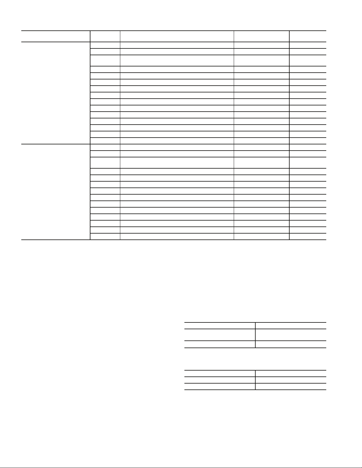
Table 2 — Accessory Package Contents
ACCESSORY PACKAGE
PART NO.
00EFN900003000A
00EFN900003100A
ITEM NO. DESCRIPTION PART NO. QTY
1 Economizer shutoff valve - 1
2 Liquid line shutoff valve - 1
3 5 Wire jacketed cable RM02EJ200
4 Cable assembly 32GB404694 5
5 Junction box HX30FZ001 2
6 Junction box cover HX38ZZ001 2
7 M6 Screws 00PPN500000302A 8
8 Cooler pipe flange - 3
10 Flex connector flange - 4 in. (102 mm) 00PSG000213300A 2
11 Loose pipe flange - 4 in. (102 mm) 00PSG000205100A 2
12 Cooler flange O-ring KK71EW256 4
13 Flex connector flange O-ring KK71EW250 2
14 Compressor flange gasket - 3 in. (76 mm) 00PPG000011702A 2
15 Compressor flange gasket - 4 in. (102 mm) 00PSG000011703A 4
16 Transducer wiring harness - 100 ft (30.5 m) 00PSN500180500A 2
1 Economizer shutoff valve - 1
2 Liquid line shutoff valve - 1
3 5 Wire jacketed cable RM02EJ200
4 Cable assembly 32GB404694 5
5 Junction box HX30FZ001 2
6 Junction box cover HX38ZZ001 2
7 M6 Screws 00PPN500000302A 8
8 Flex connector flange O-ring KK1EW250 2
9 Compressor flange gasket - 4 in. (102 mm) 00PSG000011703A 4
10 Compressor flange gasket - 5 in. (127 mm) 00PPG000011704A 4
11 Loose pipe flange - 5 in. (127 mm) 00PSG000211900A 2
12 Loose pipe flange - 4 in. (102 mm) 00PSG000205100A 2
13 Flex connector flange - 4 in. (102 mm) 00PSG000213300A 2
14 Transducer wire harness - 100 ft (30.5 m) 00PSN500180500A 2
1
/8 in. (29 mm) 00PPG000023501A 2
3
/8 in. (35 mm) EP71BA393 2
1
/8 in. (79 mm) 00PSN500091400A 2
1
/8 in. (29 mm) 00PPG000023501A 2
3
/8 in. (35 mm) EP71BA393 2
200 ft
(61 m)
200 ft
(61 m)
Choose a space that can support the weight of the cooler and
economizer with service clearances and area for refrigerant
piping. Field-supplied piping must be limited to less than
50 lineal ft (15.25 m) or 75 equivalent ft (22 m) in length.
Suction and liquid line risers must be limited to less than 15 ft
(4.5 m) vertical riser elevation. Suction lines and economizer
lines must be insulated to prevent condensation. Relocating the
cooler introduces minimal line losses if correct piping practices
are followed. Buried lines are not permitted.
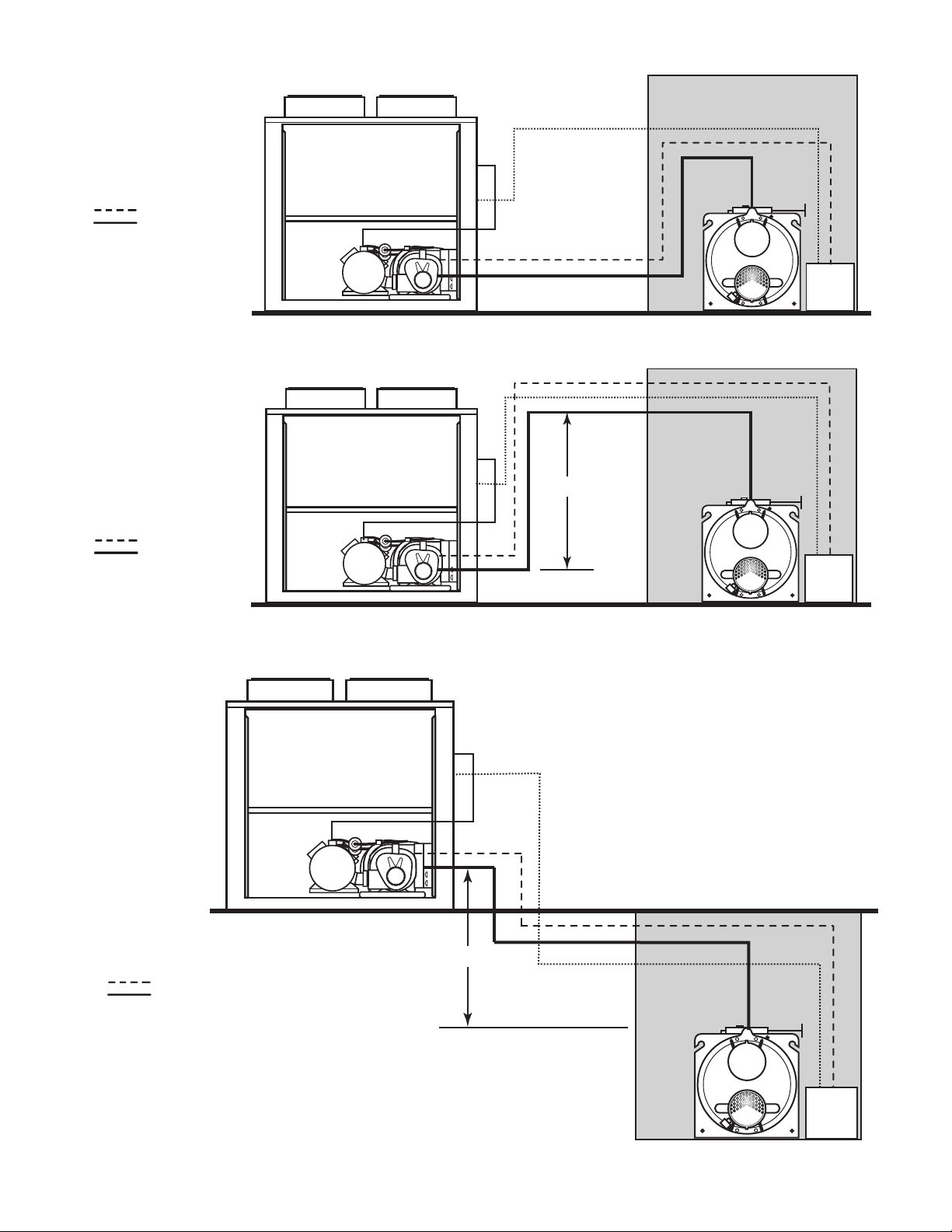
The remote cooler system can be applied in three different
configurations. See Fig. 1-3. In Fig. 1, the remote cooler and
the outdoor unit are at the same elevation. The suction, liquid,
and economizer lines run parallel between the cooler and the
outdoor unit. In Fig. 2, the outdoor unit and remote cooler are
at the same elevation, but the interconnecting piping has an elevation of up to 15 ft (4.5 m) above the base elevation of the
cooler. This could be result of running piping over a wall or
through the ceiling in a building. In Fig. 3, the remote cooler is
located below the outdoor unit. The interconnecting piping has
an elevation of up to 15 ft (4.5 m) above the base elevation of
the remote cooler. This could occur if the remote cooler is installed in a basement.
NOTE: Unit 30XA refrigeration piping can be either copper
tubing or steel tubing with flanged connections. All units are
factory charged with compressor oil to the required level.
However, when the double riser is constructed with U-bends or
street elbows, a substantial amount of oil can be trapped in the
U-bend during prolonged minimum load operation. If this
occurs, additional oil is needed to add to the system to prevent
the oil level from dropping below the minimum level in the oil
separator. Add 1 gallon of oil to each circuit. Refer to Controls,
Start-up, Operation, Service, and Troubleshooting Guide for
recommended oil type.
Table 3A — Refrigeration Piping and
Connections Material (English)
PIPE SIZE (in.) MATERIAL
5
/8, 7/8, 11/8, 13/8, 15/8,
1
2
/8, 25/8, 31/
1
2, 2
/2, 3, 31/2, 4 Schedule 40 Steel
8
Refrigeration copper
Table 3B — Refrigeration Piping and
Connections Material (SI)
PIPE SIZE (mm) MATERIAL
16, 22, 29, 35, 41, 54, 67, 79 Refrigeration copper
51, 64, 76, 89, 102 Schedule 40 Steel
2
Page 3
INDOOR LOCAT ION
LEGEND
............ Liquid Line
Economizer Line
Suction Line
a30-4509
LEGEND
............ Liquid Line
Economizer Line
Suction Line
a30-4510
30X A
REMOTE COOLER
Fig. 1 — 30XA Unit and Cooler Level, Piping Parallel (Single Circuit Shown)
INDOOR LOCAT ION
30XA
15 FT MAX
REMOTE COOLER
Fig. 2 — 30XA Unit and Cooler Level, Piping Elevated (Single Circuit Shown)
SUCTION
SERVICE
VALV E
SUCTION
SERVICE
VALV E
ECONOMIZER
ECONOMIZER
LEGEND
............ Liquid Line
Economizer Line
Suction Line
30X A
INDOOR LOCATION
15 FT MAX
REMOTE COOLER
a30-4511
Fig. 3 — 30XA Unit with Cooler Located Below Unit (Single Circuit Shown)
3
SUCTION
SE R VICE
V A L VE
ECONOMIZER
Page 4
INSTALLATION
Shut off all power to this equipment prior to installation.
There may be more than one disconnect switch. Tag all
disconnect locations to alert others not to restore power
until work is completed. Failure to disconnect power from
equipment prior to installation could result in serious
personal injury or death.
1. Inspect package contents for missing or damaged parts.
File a claim with the shipping agency if parts are
damaged and notify your local Carrier representative if
any item is missing.
2. Determine the new location for the cooler. Ensure that the
new location supports the cooler and economizers
weights and that there is enough room for service access
and tube removal. See Tables 4A and 4B to determine
refrigeration line sizes. See Table 5 for cooler and
economizers weights. See Fig. 4A-5B for cooler and
economizers dimensions, tube removal clearances, and
service areas.
3. Open and tag all electrical disconnects.
Cooler and Economizer Removal — The cooler and
economizers are accessible from the cooler side of the unit. To
remove the cooler and economizers from the unit, complete the
following steps:
1. Remove refrigerant from all circuits using standard
refrigeration practices. Refer to unit nameplate or installation instructions for refrigerant quantities.
2. Disconnect the cooler heater wiring, and conduit if
equipped.
3. Remove entering and leaving chilled water temperature
thermistors. Make sure to label thermistors as they are
removed. See Fig. 6.
4. Disconnect and label the chilled water flow switch cable
from the chilled water flow switch located on the leaving
water nozzle. See Fig. 6.
5. Disconnect the suction pressure transducer cables from
the transducers. Make sure to label cables as they are
removed. See Fig. 6.
NOTE: The suction pressure transducers (SPT) do not necessarily need to be removed. However, use care in protecting the
SPTs throughout the removal and remote installation processes,
as the SPTs are an important part of the remote installation.
6. Disconnect the electronic expansion valve (EXV) cables
from the EXVs at each economizer. Make sure to label
cables as they are removed. See Fig. 6.
NOTE: The 30XA080 units do not utilize an economizer.
In this case, only the EXVs are present.
7. Unbolt the cooler suction flanges from the cooler. Temporary supports may be needed to support the suction pipes.
See Fig 6.
8. At each circuit’s economizer, cut the liquid lines going to
the economizer assembly before the manual shutoff valve
(see Fig. 6, cut 1, circuits A and B). Cut the cooler liquid
lines between the manual shutoff valve and the cooler
(see Fig. 6, cut 2, circuits A and B). Cut the economizer
lines between the manual shutoff valve and the sensors
(see Fig. 6, cut 3, circuits A and B).
9. Remove the screws from the feet of each economizer.
Save all of the screws. Remove the economizers by carefully sliding them out the cooler side of the unit.
10. Remove the screws from the cooler feet. Save all of the
screws. Slide the cooler slightly to the left to clear the
refrigerant tubing.
11. Remove the cooler by carefully sliding the cooler out the
cooler side of the unit.
Because 30XA systems use polyolester oil, which can absorb moisture, it is important to minimize the amount of
time that the refrigeration system is left exposed to the atmosphere. Minimizing the exposure time will reduce the
amount of moisture that could possibly damage the unit.
The removal instructions minimize the exposure time to
prevent this type of damage. The remote installation instructions outline a dehydration process to counteract any
exposure that might have occurred.
Before installation of the field-supplied piping, the piping
must be thoroughly cleaned and free of dirt, debris, oil, and
welding residue. Presence of these objects will cause severe
damage to the compressors or other components of the refrigeration system.
4
Page 5
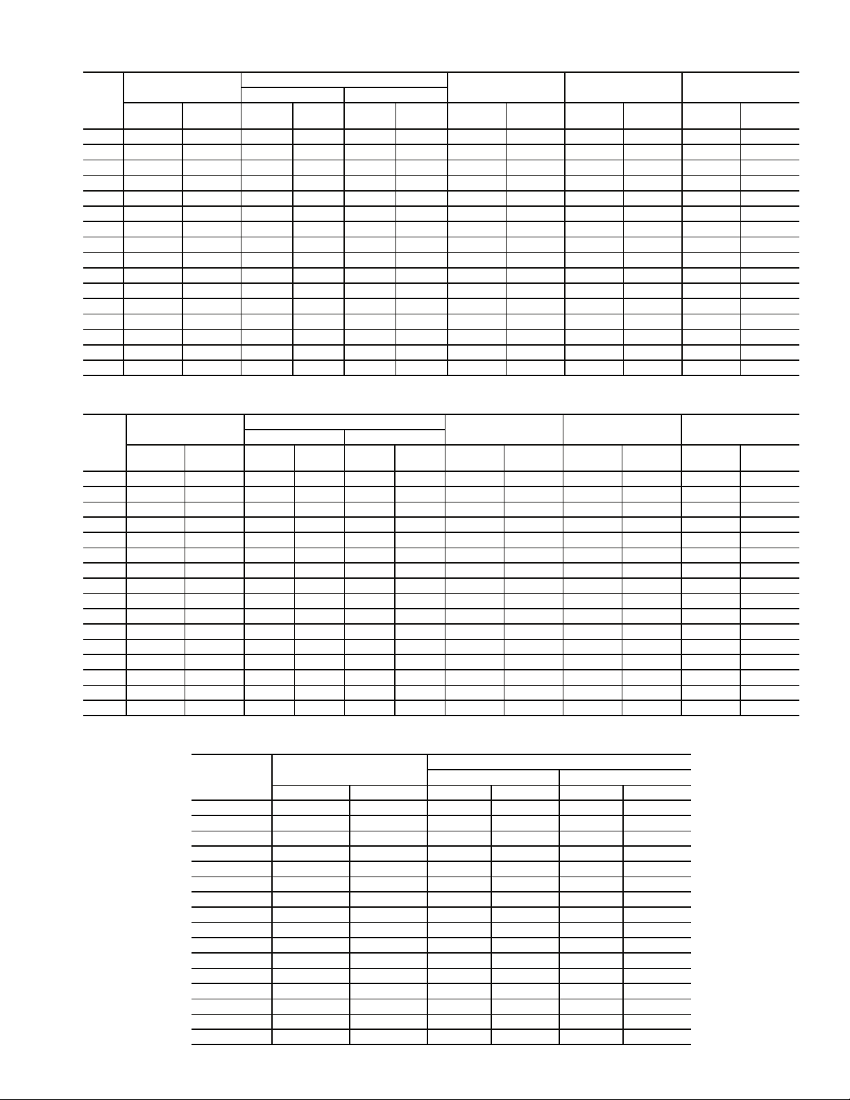
Table 4A — Refrigeration Line Sizes (English)
30XA
UNIT
SIZE
080 3
090 3
100 31/
110 31/
120 31/
140 43
160 43
SUCTION LINE
Circuit A
(in.)
1
/
8
1
/
8
8
8
8
Circuit B
(in.)
31/
8
31/
8
31/
8
31/
8
31/
8
1
/
8
1
/
8
180 4423
200 4423
220 4423
240 4423
260 442
280 442
300 442
325 442
350 442
DOUBLE SUCTION RISERS
Circuit A Circuit B
Riser A
(in.)
Riser B
(in.)
15/
15/
15/
15/
15/
23
23
1
1
1
1
1
25/
8
8
8
8
8
/
2
/
2
/
2
/
2
/
2
8
25/
8
25/
8
25/
8
25/
8
1
/
2
1
/
2
1
/
2
1
/
2
1
/
2
1
/
2
323
323
323
32
32
Riser A
(in.)
15/
15/
15/
15/
15/
15/
15/
8
8
8
8
8
8
8
Riser B
(in.)
25/
25/
25/
25/
25/
25/
25/
23
23
23
23
1
/
2
1
/
2
8
8
8
8
8
8
8
1
/
2
1
/
2
1
/
2
1
/
2
1
/
2
1
/
2
1
/
2
31
31
COOLER
LIQUID LINE
Circuit A
(in.)
11/
8
11/
8
11/
8
11/
8
11/
8
13/
8
13/
8
13/
8
13/
8
13/
8
13/
8
15/
8
15/
8
15/
8
5
/
8
5
/
8
Circuit B
(in.)
11/
8
11/
8
11/
8
11/
8
11/
8
11/
8
11/
8
13/
8
13/
8
13/
8
13/
8
13/
8
13/
8
13/
8
15/
8
15/
8
CONDENSER
LIQUID LINE
Circuit A
(in.)
11/
8
11/
8
11/
8
11/
8
11/
8
13/
8
13/
8
13/
8
13/
8
13/
8
13/
8
15/
8
15/
8
15/
8
15/
8
15/
8
Circuit B
(in.)
11/
8
11/
8
11/
8
11/
8
11/
8
11/
8
11/
8
13/
8
13/
8
13/
8
13/
8
13/
8
13/
8
13/
8
15/
8
15/
8
ECONOMIZER
LINE
Circuit A
(in.)
Circuit B
——
7
/
8
7
/
8
7
/
8
7
/
8
11/
8
11/
8
11/
8
11/
8
11/
8
11/
8
11/
8
11/
8
11/
8
11/
8
11/
8
Table 4B — Refrigeration Line Sizes (SI)
30XA
UNIT
SIZE
SUCTION LINE
Circuit A
(mm)
Circuit B
(mm)
DOUBLE SUCTION RISERS
Circuit A Circuit B
Riser A
(mm)
Riser B
(mm)
Riser A
(mm)
Riser B
(mm)
080 79 79 41 67 41 67 29 29 29 29 — —
090 79 79 41 67 41 67 29 29 29 29 22 22
100 79 79 41 67 41 67 29 29 29 29 22 22
110 79 79 41 67 41 67 29 29 29 29 22 22
120 79 79 41 67 41 67 29 29 29 29 22 22
140 102 79 51 89 41 67 35 29 35 29 29 22
160 102 79 51 89 41 67 35 29 35 29 29 22
180 102 102 51 89 51 89 35 35 35 35 29 29
200 102 102 51 89 51 89 35 35 35 35 29 29
220 102 102 51 89 51 89 35 35 35 35 29 29
240 102 102 51 89 51 89 35 35 35 35 29 29
260 102 102 64 76 51 89 41 35 41 35 29 29
280 102 102 64 76 51 89 41 35 41 35 29 29
300 102 102 64 76 51 89 41 35 41 35 29 29
325 102 102 64 76 64 76 41 41 41 41 29 29
350 102 102 64 76 64 76 41 41 41 41 29 29
COOLER
LIQUID LINE
Circuit A
(mm)
Circuit B
(mm)
CONDENSER
LIQUID LINE
Circuit A
(mm)
Circuit B
(mm)
ECONOMIZER
LINE
Circuit A
(mm)
Circuit B
(in.)
7
/
8
7
/
8
7
/
8
7
/
8
7
/
8
7
/
8
11/
11/
11/
11/
11/
11/
11/
11/
11/
(mm)
8
8
8
8
8
8
8
8
8
Table 5 — Cooler and Economizer Weights
30XA
UNIT SIZE
COOLER OPERATING
WEIGHT
lb kg lb kg lb kg
080 1277 580 — — — —
090 1323 601 45 20 45 20
100 1323 601 45 20 45 20
110 1357 617 45 20 45 20
120 1396 634 45 20 45 20
140 1622 737 45 20 55 25
160 1665 757 45 20 55 25
180 1860 845 55 25 55 25
200 1920 872 55 25 55 25
220 1980 900 55 25 60 27
240 2031 923 60 27 60 27
260 2261 1027 55 25 70 32
280 2321 1055 60 27 70 32
300 2411 1095 60 27 75 34
325 2458 1117 70 32 70 32
350 2523 1146 70 32 75 34
ECONOMIZER WEIGHT
Circuit A Circuit B
5
Page 6

13/16
(20)
117-3/4
(2991)
52-1/4
(1327)
1/2
(13)
DETAIL A
SCALE 2:1
TYP 6 PLACES
NOTES:
1. Measurements are shown in inches (millimeters).
2. Recommended service clearance around the cooler is 36 in. (914 mm).
3. Recommended cooler tube removal area (either end) is 109 in. (2769 mm).
8-9/32
(210)
SEE DETAIL A
14-11/32
(364)
57
(1447)
Fig. 4A — 30XA080-120 Cooler Dimensions
52-1/4
(1327)
SIDE VIEW
14-11/32
BOTTOM VIEW
(364)
52-1/4
(1327)
21-1/32
(534)
14-11/32
(364)
18-21/32
(474)
a30-4512
13/16
(20)
1/2
(13)
A
DETAIL
SCALE 2:1
TYP 6 PLACES
10-23/32
(272)
SEE DETAIL
15-5/16
(389)
A
64
(1625)
NOTES:
1. Measurements are shown in inches (millimeters).
2. Recommended service clearance around the cooler is 36 in. (914 mm).
3. Recommended cooler tube removal area (either end) is 109 in. (2769 mm).
Fig. 4B — 30XA140, 160 Cooler Dimensions
118-13/16
(3017)
52-1/4
(1327)
52-1/4
(1327)
SIDE VIEW
BOTTOM VIEW
15-5/16
(389)
45-1/4
(1149)
19-21/32
15-5/16
(389)
a30-4513
23-1/32
(585)
(499)
6
Page 7

13/16
(20)
119-9/32
(3030)
52-1/4
(1327)
11-3/16
1/2
(13)
A
DETAIL
SCALE 2:1
TYP 6 PLACES
NOTES:
1. Measurements are shown in inches (millimeters).
2. Recommended service clearance around the cooler is 36 in. (914 mm).
3. Recommended cooler tube removal area (either end) for 30XA180, 200 is 109
4. Recommended cooler tube removal area (either end) for 30XA220, 240 is 1085/8 in. (2758 mm).
(284)
SEE DETAIL
18-3/8
(466)
52-1/4
(1327)
A
57
(1448)
SIDE VIEW
18-3/8
(466)
BOTTOM VIEW
3
/8 in. (2779 mm).
Fig. 4C — 30XA180-240 Cooler Dimensions
52-1/4
(1327)
25-1/16
(636)
22-11/16
18-3/8
(576)
(466)
a30-4514
13/16
(20)
1/2
(13)
DETAIL
SCALE 1:1
TYP 6 PLACES
NOTES:
1. Measurements are shown in inches (millimeters).
2. Recommended service clearance around the cooler is 36 in. (914 mm).
3. Recommended cooler tube removal area (either end) for 30XA260-300 is 188
4. Recommended cooler tube removal area (either end) for 30XA325, 350 is 232
11-7/16
2
(290)
(50)
A
SEE DETAIL
A
20-11/32
(516)
16-3/8
(416)
52-1/4
(1327)
118-5/32
(3002)
64-7/8
(1648)
52-9/32
(1328)
SIDE VIEW
16-3/8
(416)
BOTTOM VIEW
3
/8 in. (4784 mm).
21
/32 in. (5910 mm).
20-11/32
(516)
57
(1448)
20-11/32
(516)
16-3/8
(416)
a30-4515
27-1/8
(689)
24-21/32
(626)
Fig. 4D — 30XA260-350 Cooler Dimensions
7
Page 8

22-7/8
(581)
23-1/2
(598)
30-3/8
(770)
SIDE VIEW END VIEW
6-1/2
(166)
5/8
2 x Ø 7/16 (11)
29-3/8
(746)
7/16
(12)
(17)
TOP VIEW
NOTES:
1. Measurements are shown in inches (millimeters).
2. Recommended service clearance around the economizer is 36 in. (914 mm).
Fig. 5A — 30XA090-160 Economizer Dimensions
7-7/8
(200)
7/16
(11)
a30-4516
7/8
(21)
23-1/32
(585)
30-3/4
(781)
SIDE VIEW END VIEW
2-1/4
8-3/4
(56)
(222)
4 x Ø 7/16 (11)
29-3/8
(746)
7/16
(12)
5/8
(17)
TOP VIEW
NOTES:
1. Measurements are shown in inches (millimeters).
2. Recommended service clearance around the economizer is 36 in. (914 mm).
Fig. 5B — 30XA180-350 Economizer Dimensions
8
7-7/8
(256)
7/16
(11)
24-1/4
(611)
a30-4517
7/8
(21)
Page 9

CUT 1
(LIQUID LINE)
CUT 3
(ECONOMIZER
LINE)
CIRCUIT A
ELECTRONIC
EXPANSION
VALV ES (2)
MANUAL SHUTOFF
VALVE
CHILLED WATER
FLOW SWITCH
1. Circuit A uses steel suction piping.
2. Circuit B uses copper suction piping.
NOTES:
SUCTION PRESSURE
TRANSDUCER
SUCTION PRESSURE
(HIDDEN)
CUT 3
(ECONOMIZER
CUT 2
(COOLER
TRANSDUCER
(HIDDEN)
LINE)
LIQUID LINE)
ENTERING CHILLED WATER
ELECTRONIC
EXPANSION
VALV ES (2)
COOLER
SUCTION
FLANGES
LEAVING CHILLED WATER
THERMISTORS
CIRCUIT A
(CONT.)
Fig. 6 — Typical Cooler Piping-Cooler Side View (30XA140, 160 Shown)
CUT 4
(SUCTION
LINE)
CUT 1
(LIQUID LINE)
MANUAL
SHUTOFF
VALVE
CUT 2
(COOLER
LIQUID LINE)
9
CIRCUIT B
a30-4518
Page 10

Remote Cooler and Economizers Installation —
location by following this procedure:
NOTE: Throughout the Remote Cooler and Economizers
Installation steps, the two accessory package part no.
(00EFN900003000A, 00EFN900003100A) have been shortened to 3000A and 3100A. When a specific part is referred to
in each accessory’s package, the package no. is mentioned followed by the item no. For item no. identification and accessory
package contents, refer to Table 2.
NOTE: The 30XA080 units do not utilize an economizer. In
this case, keep the EXV as close to the cooler as possible.
NOTE: The original flanges on the cooler and cut from the
30XA base unit may still be usable. However, Carrier recommends and has provided in the accessory kit, parts necessary to
replace both the cooler pipe flange and the suction flange.
When the extended piping is installed, these flanges should be
replaced.
Install the cooler and economizers in a remote
1. After removing the cooler from the base unit, strip back
the insulation on the cooler tube sheets (if required) and
use the two large holes in the top corners for lifting.
2. Transport the cooler and economizer assemblies to the
new location and secure them into position. Keep the
economizer assemblies as close to the cooler as possible.
Also, ensure there is sufficient room to install and remove
cooler tubes from either end of the cooler. See Fig. 4A4D for tube removal clearances.
3. Install the accessory-supplied economizer shutoff valves
(3000A or 3100A: Item 1) and liquid line shutoff valves
(3000A or 3100A: Item 2) on the two economizer lines
and liquid lines at circuits A and B on the 30XA base
unit. See Fig. 7.
4. At the new cooler location, connect the field-supplied
cooler liquid line piping between the factory-installed
manual shutoff valve at the two economizer assemblies
and at the cooler. See Fig. 7.
5. Following good piping practices, install additional fieldsupplied liquid and economizer line piping in the required
length to reconnect the two economizer assemblies to the
30XA base unit. See Fig. 8 for double suction riser construction detail.
Do NOT close both manual shutoff valves in one liquid
line. Pressure can build up in the trapped area. To avoid the
possibility of personal injury or property damage, the new
liquid lines between the manual shutoff valves must each
have field-supplied and installed pressure relief valves.
6. For 30XA080-120: all circuits and 30XA140-160: circuit
B, cut the suction pipe (copper) at the 30XA base unit and
discard (see Fig. 6, cut 4, circuit B). Following good
piping practices, install field-supplied copper suction line
piping from the 30XA base unit to the cooler. Use the
accessory-supplied cooler pipe flange (3000A: Item 8),
cooler flange O-ring (3000A: Item 12), and loose pipe
flange (3000A: Item 11) to connect the field-supplied
copper suction line piping at the cooler. See Fig. 9.
7. For 30XA140-160: circuit A and 30XA180-350: all
circuits, unbolt (DO NOT CUT) the portion of the steel
suction pipes that connected the flex connector flanges to
the cooler at the 30XA base unit and discard. See Fig. 10.
Refer to Table 6 for parts required (field-supplied or
accessory-supplied) to make new connections at the
cooler and the 30XA base unit with the field-supplied
steel suction line. See Fig 11. Follow good piping
practices to install field-supplied steel suction line piping
between the cooler and the flex connector at the 30XA
base unit.
When field-supplied flanges and gaskets are used, an
extra M16 mounting hole must be drilled and tapped to
connect a mounting bracket at the 30XA base unit. See
Fig. 10 and 11 for mounting bracket placement. See
Fig. 12 for mounting hole locations.
If additional gaskets are needed for installation, they must
1
be
/16 in. non-asbestos fiber with synthetic rubber binder
compressed gasket sheet. An extra mounting hole also
needs to be field modified for any additional gaskets. See
Fig. 12 for mounting hole locations. Field-supplied
mounting nuts and bolts are also needed for fieldsupplied gaskets.
8. All of the piping connections are now complete. Leak test
the unit and then pull a deep dehydration vacuum. Connect the vacuum pump to the high-flow access fitting at
the bottom of the cooler, the liquid line service valves,
and the economizer line service valves. For best results, it
is recommended that a vacuum of at least 500 microns
(0.5 mm Hg) be obtained. To perform a standing vacuum
rise test, observe the rate-of-rise of the vacuum in the
system. If the vacuum rises by more than 50 microns in a
30-minute time period, then continue the dehydration
process until the standing vacuum requirement is met.
This will ensure a dry system.
By following this dehydration procedure, the amount of
moisture present in the system will be minimized, and the
factory-supplied filter driers will provide adequate
moisture protection. It is highly recommended that the
filter drier cores be replaced after 24 hours of operation.
This is to ensure that any foreign debris that is captured
during start-up is removed from the system. Additional
moisture removal capacity is also provided.
9. After setup is leak tested and deep dehydration vacuum is
completed, install field-supplied suction and economizer
line insulation between the economizer and the unit. If
necessary, reinstall the insulation on the cooler head.
10. To reconnect the EXV cables, use the accessory-supplied
cable assemblies (3000A or 3100A: Item 4). Two cables
are needed for the 30XA080 unit, and four cables are
needed for 30XA090-350 units. Take one cable assembly,
and label both ends with “EXV-A” for the circuit A main
EXV. Then label another three cable assemblies the same
way with “EXV-B”, “ECEXV-A”, “ECEXV-B” for the
circuit B main EXV, circuit A economizer EXV, and
circuit B economizer EXV, respectively (economizer
EXV does not apply to 30XA080 units).
Plug one side of the electrical connectors of the EXV
labeled cables into their corresponding EXV plugs. Run
the cables to the 30XA base unit, and plug the other side
of the cable connectors into their corresponding EXV
leads. Coil excess cables and wire tie in a convenient
location.
11. To reconnect the flow switch cable, use the accessorysupplied cable assembly (3000A or 3100A: Item 4). Take
one cable assembly and label both ends with “CWFS.”
Plug one side of the electrical connector of the labeled
cable into the flow switch plug. Run the cable to the base
unit, and plug the other side of the cable connector into
the flow switch lead. Coil excess cables and wire tie in a
convenient location.
10
Page 11

12. Using the accessory-supplied M6 screws (3000A or
3100A: Item 6), install the accessory-supplied junction
box (3000A or 3100A: Item 5) at the desired location
where the entering and leaving water thermistor cables
can be conveniently spliced. One or two knockouts can
be used. Follow all local codes. Remove one knockout
from the junction box and install the field-supplied strain
relief at the knockout hole. If using field-supplied conduit
to provide mechanical protection to the thermistor wires
between the cooler and the 30XA base unit, remove
another knockout.
13. To reconnect the thermistors, locate the entering water
thermistor and leaving water thermistor and cut both
leads where they can be spliced in the installed junction
box. Cut, strip, and label both sides of the entering water
thermistor lead “EWT.” Cut, strip, and label the leaving
water thermistor lead the same way, with “LWT” on both
sides. See Fig. 13.
14. Run the labeled thermistor leads connected to the unit
into the installed junction box and tighten the fieldsupplied strain relief. Strip back the lead jackets to expose
the two wires in each lead.
15. Take one of the accessory-supplied 5-wire jacketed cables (3000A or 3100A: Item 3) to connect the thermistor
leads in the installed junction box to the cooler location.
Each wire in the jacketed cable is a different color. Cut
the cable into two pieces so that each has a maximum
length of 100 ft (30.5 m).
16. Select one jacketed cable and strip back the jacket on
both ends to expose the five wires. Pick any two wires
and label both ends of each wire “EWT.” Pick another
pair of wires and label both ends “LWT.” The fifth wire is
not used. See Fig. 14.
17. Run one end of the accessory-supplied 5-wire jacketed
cable into the installed junction box and splice the identically labeled thermistor leads. Solder the splices and insulate them to prevent shorting. Tighten the field-supplied
strain relief for the cables.
18. Run the other end of the accessory-supplied 5-wire
jacketed cables back to the cooler. Splice the labeled
jacketed cable wires to the matching thermistors. If a
second junction box is necessary at the cooler location,
use the second accessory-supplied junction box (3000A
or 3100A: Item 5).
19. Reinstall the thermistors in the correct cooler wells.
20. To reconnect the suction pressure transducers (SPT),
locate the SPT plugs for circuits A and B, and cut the
leads where they can be conveniently spliced in the
installed junction box at the 30XA base unit. Label the
leads “SPTA” for the circuit A lead, and “SPTB” for the
circuit B lead.
21. Take the two pieces of accessory-supplied transducer
wire harness (3000A: Item 16 or 3100A: Item 14). One
side of the harness is a plug and the other side is three
wires in red, black, and green. Label both sides of one
harness “SPTA,” and label the other harness “SPTB.”
Remove one knockout from an installed junction box and
install a field-supplied strain relief valve at the knockout
hole. If using field-supplied conduit to provide mechanical protection to the transducer wires between the cooler
and the 30XA base unit, remove another knockout.
22. Run the labeled transducer leads connected to the unit
into the installed junction box at the 30XA base unit and
tighten the field-supplied strain relief. Strip back the lead
jackets to expose the three wires, black, red, and white.
23. Run the lead end of accessory-supplied transducer wire
harnesses into the junction box and splice the identically
labeled leads. The red wire should go with red wire, the
black wire with the black wire, and the white wire with
the green wire. Solder the splices and insulate them to
prevent shorting. Tighten the field-supplied strain relief
for the cables and secure the accessory-supplied junction
box cover (3000A or 3100A: Item 6) with accessorysupplied M6 screws.
24. Run the plug end of the accessory-supplied transducer
wire harness back to the cooler. Connect the “SPTA” plug
into the circuit A transducer. Connect the “SPTB” plug
into the circuit B transducer. See Fig. 13.
25. Charge the unit to the amount of refrigerant as specified
on the 30XA base unit nameplate. Because of longer
field-installed liquid, economizer, and suction lines, additional charge is needed. Refer to Table 7 to calculate the
additional charge for each circuit and then add it to the
nameplate charge. Additional charge for the economizer
line is NOT required.
26. Perform all pre-start-up and start-up procedures specified
in the unit operation instructions. Follow the checklist
provided with the unit operation instructions.
27. Verify unit operation.
11
Page 12

Table 6 — Materials Required for Steel Piping Flange Connections
UNIT
SIZE
140 Field supplied:
ASME B16.9 Stub End 4 in.
(102 mm)
Accessory supplied:
Compressor Flange Gasket
(3000A: Item 15),
Loose Pipe Flange
(3000A: Item 11)
160 Field supplied:
ASME B16.9 Stub End 4 in.
(102 mm)
Accessory supplied:
Compressor Flange Gasket
(3000A: Item 15),
Loose Pipe Flange
(3000A: Item 11)
180 Field supplied:
ASME B16.9 Stub End 4 in.
(102 mm)
Accessory supplied:
Compressor Flange Gasket
(3000A: Item 15),
Loose Pipe Flange
(3000A: Item 11)
200 Field supplied:
ASME B16.9 Stub End 4 in.
(102 mm)
Accessory supplied:
Compressor Flange Gasket
(3000A: Item 15),
Loose Pipe Flange
(3000A: Item 11)
220 Field supplied:
ASME B16.9 Stub End 4 in.
(102 mm)
Accessory supplied:
Compressor Flange Gasket
(3100A: Item 9),
Loose Pipe Flange
(3100A: Item 11)
240 Field supplied:
ASME B16.9 Stub End 4 in.
(102 mm)
Accessory supplied:
Compressor Flange Gasket
(3100A: Item 9),
Loose Pipe Flange
(3100A: Item 11)
260 Field supplied:
ASME B16.9 Stub End 4 in.
(102 mm)
Accessory supplied:
Compressor Flange Gasket
(3100A: Item 9),
Loose Pipe Flange
(3100A: Item 11)
COOLER PIPE FLANGE CONNECTION FLEX CONNECTOR FLANGE CONNECTION
Circuit A Circuit B Circuit A Circuit B
N/A* Accessory supplied:
N/A* Accessory supplied:
Field supplied:
ASME B16.9 Stub End 4 in.
(102 mm)
Accessory supplied:
Compressor Flange Gasket
(3000A: Item 15),
Loose Pipe Flange
(3000A: Item 11)
Field supplied:
ASME B16.9 Stub End 4 in.
(102 mm)
Accessory supplied:
Compressor Flange Gasket
(3000A: Item 15),
Loose Pipe Flange
(3000A: Item 11)
Field supplied:
ASME B16.9 Stub End 4 in.
(102 mm)
Accessory supplied:
Compressor Flange Gasket
(3100A: Item 9),
Loose Pipe Flange
(3100A: Item 12)
Field supplied:
ASME B16.9 Stub End 4 in.
(102 mm)
Accessory supplied:
Compressor Flange Gasket
(3100A: Item 9),
Loose Pipe Flange
(3100A: Item 11)
Field supplied:
ASME B16.9 Stub End 4 in.
(102 mm)
Accessory supplied:
Compressor Flange Gasket
(3100A: Item 9),
Loose Pipe Flange
(3100A: Item 12)
LEGEND
3000A — Accessory Package Part No. 00EFN900003000A (30XA080-200)
3100A — Accessory Package Part No. 00EFN900003100A (30XA220-350)
Item — Item No. (See Table 2)
*Copper connection.
Flex Connector Flange
(3000A: Item 10),
Flex Connector Flange
O-ring
(3000A: Item 13)
Flex Connector Flange
(3000A: Item 10),
Flex Connector Flange
O-ring
(3000A: Item 13)
Accessory supplied:
Flex Connector Flange
(3000A: Item 10),
Flex Connector Flange
O-ring
(3000A: Item 13)
Accessory supplied:
Flex Connector Flange
(3000A: Item 10),
Flex Connector Flange
O-ring
(3000A: Item 13)
Accessory supplied:
Flex Connector Flange
(3100A: Item 13),
Flex Connector Flange
O-ring
(3100A: Item 8)
Accessory supplied:
Flex Connector Flange
(3100A: Item 13),
Flex Connector Flange
O-ring
(3100A: Item 8)
Field supplied:
ASME B16.5 Class 600
Flange 4 in. (102 mm)
Accessory supplied:
Compressor Flange Gasket
(3100: Item 10)
N/A*
N/A*
Accessory supplied:
Flex Connector Flange
(3000A: Item 10),
Flex Connector Flange
O-ring
(3000A: Item 13)
Accessory supplied:
Flex Connector Flange
(3000A: Item 10),
Flex Connector Flange
O-ring
(3000A: Item 13)
Accessory supplied:
Flex Connector Flange
(3100A: Item 13),
Flex Connector Flange
O-ring
(3100A: Item 8)
Accessory supplied:
Flex Connector Flange
(3100A: Item 13),
Flex Connector Flange
O-ring
(3100A: Item 8)
Accessory supplied:
Flex Connector Flange
(3100A: Item 13),
Flex Connector Flange
O-ring
(3100A: Item 8)
12
Page 13

Table 6 — Materials Required for Steel Piping Flange Connections (cont)
UNIT
SIZE
280 Field supplied:
ASME B16.9 Stub End 4 in.
(102 mm)
Accessory supplied:
Compressor Flange Gasket
(3100A: Item 9),
Loose Pipe Flange
(3100A: Item 11)
300 Field supplied:
ASME B16.9 Stub End 4 in.
(102 mm)
Accessory supplied:
Compressor Flange Gasket
(3100A: Item 9),
Loose Pipe Flange
(3100A: Item 11)
325 Field supplied:
ASME B16.9 Stub End 4 in.
(102 mm)
Accessory supplied:
Compressor Flange Gasket
(3100A: Item 9),
Loose Pipe Flange
(3100A: Item 11)
350 Field supplied:
ASME B16.9 Stub End 4 in.
(102 mm)
Accessory supplied:
Compressor Flange Gasket
(3100A: Item 9),
Loose Pipe Flange
(3100A: Item 11)
COOLER PIPE FLANGE CONNECTION FLEX CONNECTOR FLANGE CONNECTION
Circuit A Circuit B Circuit A Circuit B
Field supplied:
ASME B16.9 Stub End 4 in.
(102 mm)
Accessory supplied:
Compressor Flange Gasket
(3100A: Item 9),
Loose Pipe Flange
(3100A: Item 11)
Field supplied:
ASME B16.9 Stub End 4 in.
(102 mm)
Accessory supplied:
Compressor Flange Gasket
(3100A: Item 9),
Loose Pipe Flange
(3100A: Item 11)
Field supplied:
ASME B16.9 Stub End 4 in.
(102 mm)
Accessory supplied:
Compressor Flange Gasket
(3100A: Item 9),
Loose Pipe Flange
(3100A: Item 11)
Field supplied:
ASME B16.9 Stub End 4 in.
(102 mm)
Accessory supplied:
Compressor Flange Gasket
(3100A: Item 9),
Loose Pipe Flange
(3100A: Item 11)
LEGEND
3000A — Accessory Package Part No. 00EFN900003000A (30XA080-200)
3100A — Accessory Package Part No. 00EFN900003100A (30XA220-350)
Item — Item No. (See Table 2)
*Copper connection.
Table 7 — Additional Refrigerant Charges Required
Field supplied:
ASME B16.5 Class 600
Flange 4 in. (102 mm)
Accessory supplied:
Compressor Flange Gasket
(3100: Item 10)
Field supplied:
ASME B16.5 Class 600
Flange 4 in. (102 mm)
Accessory supplied:
Compressor Flange Gasket
(3100: Item 10)
Field supplied:
ASME B16.5 Class 600
Flange 4 in. (102 mm)
Accessory supplied:
Compressor Flange Gasket
(3100: Item 10)
Field supplied:
ASME B16.5 Class 600
Flange 4 in. (102 mm)
Accessory supplied:
Compressor Flange Gasket
(3100: Item 10)
Accessory supplied:
Flex Connector Flange
(3100A: Item 13),
Flex Connector Flange
O-ring
(3100A: Item 8)
Accessory supplied:
Flex Connector Flange
(3100A: Item 13),
Flex Connector Flange
O-ring
(3100A: Item 8)
Field supplied:
ASME B16.5 Class 600
Flange 4 in. (102 mm)
Accessory supplied:
Compressor Flange Gasket
(3100: Item 10)
Field supplied:
ASME B16.5 Class 600
Flange 4 in. (102 mm)
Accessory supplied:
Compressor Flange Gasket
(3100: Item 10)
LINE SIZE
LIQUID LINE
lb (kg) OF
R-134a REFRIGERANT
PER FOOT (305 mm)
SUCTION LINE
lb (kg) OF
R-134a REFRIGERANT
PER FOOT (305 mm)
in.mmlbkg lbkg
1
/
1
1
1
3
29 0.41 0.186 — —
8
3
/
35 0.64 0.2903 — —
8
5
/
41 0.89 0.4037 — —
8
1
/
79 — — 0.05 0.0227
8
4 102 — — 0.09 0.0408
13
Page 14

A
30XA
MANUAL
SHUTOFF
VALVE
FLANGE
CONNECTION
PRESSURE RELIEF
VALV ES (FIELD-
SUPPLIED)
ECONOMIZER
LINE
LIQUID LINE
(30XA TO
ECONOMIZER)
FLANGE
CONNECTION
COOLER LIQUID LINE
(ECONOMIZER TO COOLER)
SUCTION LINE
MANUAL SHUTOFF
VALV E
NOTE: All shaded piping is field supplied and installed.
Fig. 7 — Line Piping and Connections (1 Circuit Shown)
TO 30X
ECONOMIZER
COOLER
a30-4519
LOOSE PIPE FLANGE
(ACCESSORY-SUPPLIED)
A
RED.
TEE
FROM
COOLER
45 DEGREE
STR ELLS
LEGEND
RED. TEE — Reducing Tee
STR ELLS— Street Elbows
Fig. 8 — Double Suction Riser
Construction Detail
B
90 DEGREE
STR ELLS
a30-4507
O-RING
(ACCESSORY-SUPPLIED)
COOLER PIPE FLANGE
(ACCESSORY-SUPPLIED)
a30-4520
Fig. 9 — Connect Copper Suction Line at the Cooler
(30XA080-120: All Circuits and
30XA140-160: Circuit B)
14
Page 15

Fig. 10 — Unbolt Portion Between Flex Connector and Cooler
(30XA140, 160: Circuit A and 30XA180-350: All Circuits)
22.5°
45.0°
a30-4521
ASME B16.9
STEEL STUB END
(FIELD-SUPPLIED)
PIPE FLANGE
(ACCESSORY-SUPPLIED,
SEE TABLE 6)
MOUNTING
BRACKET
EXISTING FLANGE
ON FLEX
CONNECTOR AT
30XA BASE UNIT
a30-4522
Fig. 11 — Connect Steel Suction Line at the 30XA
Base Unit (Shown) and Cooler
(30XA140, 160: Circuit A and
30XA180-350: All Circuits)
8-1/2 (215.9)
8 HOLES 1 (25)
EQUALLY SPACED
1 EXTRA HOLE M16
a30-4523
NOTES:
1. Measurements are shown in inches (millimeters).
2. Accessory-supplied flanges and gaskets connecting to the flex
connector: extra hole has been factory-drilled and tapped. See
Table 2 (3000A: Item 10, 14, 15 and 3100A: Item 9, 10, 13).
3. Field-supplied flanges and gaskets connecting to the flex connector: extra hole must be field-drilled and tapped (M16).
4. The extra hole allows a bolt to slide through and mount the flanges
and gaskets of the suction line on a mounting bracket at the 30XA
base unit. See Fig. 10 and 11.
Fig. 12 — Flange and Gasket Mounting Locations
15
7-7/8 (200)
Page 16

MAIN
BASE
BOARD
a30-4524
LEGEND
DPT — Discharge Pressure Transducer
LWT — Leaving Water Temperature
OAT — Outdoor Air Temperature
SPT — Suction Pressure Transducer
Fig. 13 — Thermistor Connections
EWT
EWT
LWT
LWT
STRAIN RELIEF
(FIELD-SUPPLIED)
EWT
LWT
EWT
LWT
LWT
EWT
JUNCTION
BOX
(ACCESSORYSUPPLIED)
5-WIRE CABLE
(ACCESSORY-SUPPLIED)
CONDUIT
(FIELD-SUPPLIED)
a30-4508
Fig. 14 — Typical Junction Box Connections
(EWT and LWT Thermistors Shown)
Copyright 2007 Carrier Corporation
Manufacturer reserves the right to discontinue, or change at any time, specifications or designs without notice and without incurring obligations.
Book 2
Ta b 5 c
Catalog No. 04-53300012-01 Printed in U.S.A. Form 30XA-7SI Pg 16 3-07A 1-07 Replaces: New
 Loading...