


REACH-IN CO2 INCUBATOR
OPERATIONS MANUAL
For Models
7400-25, 7400-33, 7401-25, 7401-33 7402-25, 7402-33, 7403-25, 7403-33
PO Box 715 Marietta, OH 45750
800-648-3042 740-373-6809 Fax 740-374-3760 www.caronproducts.com service@caronproducts.com
Dear Valued Customer:
Thank you for purchasing CARON Products & Services equipment. We appreciate your business and look forward to being your preferred supplier of controlled environment equipment products in the future.
At CARON, we are committed to continuous quality improvement. Our goal is to supply our customers with highly reliable equipment at a fair price. In order to openly monitor our performance, we would appreciate your feedback on our products and services.
If you have questions, or any suggestions for improvement based on the installation or operation of the equipment you have purchased, please contact our service department at service@caronproducts.com or 740-373-6809.
Thanks again for your business!
7400 Series Operations Manual |
Rev A 07/25/14 |
Page 2 of 83 |
TABLE OF CONTENTS |
|
|
Section 1 – Warranty .......................................................................................... |
|
5 |
Section 2 – Equipment Overview..................................................................... |
10 |
|
Section 3 – Equipment Installation.................................................................. |
12 |
|
Unpacking |
|
|
Choosing a Location |
|
|
Preliminary Cleaning |
|
|
Installing the Port Stopper |
|
|
Installing the Shelves |
|
|
Leveling the Unit |
|
|
Connecting the Drain Line |
|
|
Water Supply for Humidity |
|
|
Connecting CO2 supply |
|
|
Connecting Electrical Power |
|
|
Cell Roller / Reinforced Shelf |
|
|
Section 4 – Optional Accessory Installation .................................................. |
17 |
|
Connecting Alarm Contacts (ALRM302) |
|
|
Installing Carboy water system (BOTL301) |
|
|
Connecting to Humidity (HUMD304, HUMD307) |
|
|
Connecting Alarm Contacts (OUTP302, OUTP303) |
|
|
Install a Drain Water Pump (PUMP301) |
|
|
Section 5 – Operation ....................................................................................... |
|
22 |
Using the Keypad |
|
|
Learning the Screen Saver |
|
|
Changing the Temperature Set-point |
|
|
Changing the Humidity Set-point |
|
|
Changing the CO2 Set-point |
|
|
Section 6 – Optional Accessory Operation .................................................... |
31 |
|
Carboy water system (BOTL301) |
|
|
Decontamination Cycle (DECN301) |
|
|
Using the Extended Temperature Range (EXTD302) |
|
|
Built in Gas Guard System (GASG302) |
|
|
Ultraviolet Germicidal Lamp (LGHT602) |
|
|
Interior Electrical Outlet (OUTL305-OUTL320) |
|
|
Built in Temp or Temp/Rh 6” Pen Recorders (RCDR316/RCDR317) |
||
Built in Temp or Temp/Rh 10” Thermal Recorders (RCDR318/RCDR319) |
||
7400 Series Operations Manual |
Rev A 07/25/14 |
Page 3 of 83 |
Section 7 – Calibration ..................................................................................... |
47 |
Calibrating the Temperature |
|
Calibrating the Humidity |
|
Calibrating the CO2 |
|
Section 8 – Alarms ........................................................................................... |
51 |
Alarm System Overview |
|
Snoozing the Speaker |
|
Muting the Speaker |
|
Changing Alarm Set-points |
|
Section 9 – Alerts ............................................................................................. |
57 |
Alert System Overview |
|
Maintenance |
|
Section 10 – Info ............................................................................................... |
60 |
Info System Overview |
|
Section 11 – Advanced Features .................................................................... |
61 |
Setting the time & day |
|
Locking the controls |
|
Changing the Passcode |
|
Factory menu & troubleshooting |
|
Section 12 – Preventative Maintenance ......................................................... |
74 |
Section 13 – Specifications ............................................................................. |
76 |
Section 14 – Electrical Schematics ................................................................ |
79 |
Section 15 – Troubleshooting.......................................................................... |
81 |
Section 16 – Spare Replacement Parts .......................................................... |
82 |
Appendix A – Declaration of Conformity ........................................................ |
84 |
7400 Series Operations Manual |
Rev A 07/25/14 |
Page 4 of 83 |
SECTION 1- WARRANTY INFORMATION
CO2 INCUBATOR LIMITED WARRANTY
Please review this section before requesting warranty service. At CARON, one of our primary goals is to provide customers with high levels of personal service and top quality products, delivered on time, backed by technical service and supported for the life of the product.
Before contacting us for warranty service, please be aware that there are repairs that are not covered under warranty.
WARRANTY DEFINED
Caron Products & Services, Inc. (herein after CARON) hereby warrants that equipment manufactured by CARON is free from defects in materials and workmanship when the equipment is used under normal operating conditions in accordance with the instructions provided by CARON.
COVERED:
Parts and labor for a period of two (2) years from date of shipment.
Any part found defective will be either repaired or replaced at CARON's discretion, free of charge, by CARON in Marietta, OH. Parts that are replaced will become the property of CARON.
If CARON factory service personnel determine that the customer's unit requires further service, dependent of the model involved, CARON may, at its sole discretion, provide a service technician to correct the problem, or require the return of the equipment to the factory or authorized service depot.
CARON will have the right to inspect the equipment and determine the repairs or replacement parts necessary. The customer will be notified, within a reasonable time after inspection, of any costs incurred that are not covered by this warranty prior to initiation of any such repairs.
NOT COVERED:
Calibration of control parameters.
Improper installation; including electrical service, gas and water supply tubing, gas supplies, room ventilation, unit leveling, facility structural inadequacies or ambient conditions that are out of specification.
Cost of express shipment of equipment or parts.
Any customer modifications of this equipment, or any repairs undertaken without the prior written consent of CARON, will render this limited warranty void.
CARON is not responsible for consequential, incidental or special damages; whether shipping damage or damages that may occur during transfer to the customer’s point of use. When the equipment is signed for at the customer’s site, ownership is transferred to the customer. Any damage claims against the shipping company become the responsibility of the customer.
Repairs necessary because of the equipment being used under other than normal operating conditions or for other than its intended use.
Repair due to the customer's failure to follow normal maintenance instructions.
Parts considered consumable; including: light bulbs, filters, gases, etc.
Damage from use of improper water quality.
Damage from chemicals or cleaning agents detrimental to equipment materials.
Force Majeure or Acts of God.
7400 Series Operations Manual |
Rev A 07/25/14 |
Page 5 of 83 |
This writing is a final and complete integration of the agreement between CARON and the customer.
CARON makes no other warranties, express or implied, of merchantability, fitness for a particular purpose or otherwise, with respect to the goods sold under this agreement. This warranty cannot be altered unless CARON agrees to an alteration in writing and expressly stated herein shall be recognized to vary or modify this contract.
Ohio Law governs this warranty.
7400 Series Operations Manual |
Rev A 07/25/14 |
Page 6 of 83 |
EQUIPMENT INTERNATIONAL LIMITED WARRANTY
Please review this section before requesting warranty service. At CARON, one of our primary goals is to provide customers with high levels of personal service and top quality products, delivered on time, backed by technical service and supported for the life of the product.
Before contacting your distributor for warranty service, please be aware that there are repairs that are not covered under warranty.
WARRANTY DEFINED
Caron Products & Services, Inc. (herein after CARON) hereby warrants that equipment manufactured by CARON is free from defects in materials and workmanship when the equipment is used under normal operating conditions in accordance with the instructions provided by CARON.
COVERED:
Parts for a period of two (2) years from date of shipment.
Any part found defective will be either repaired or replaced at CARON's or their authorized representative’s discretion. Parts that are replaced will become the property of CARON.
If CARON or their authorized representatives determine that the customer's unit requires further service, CARON or the representative may, at its sole discretion, provide a service technician to correct the problem, or require the return of the equipment to the an authorized service depot.
CARON or their authorized representative will have the right to inspect the equipment and determine the repairs or replacement parts necessary. The customer will be notified, within a reasonable time after inspection, of any costs incurred that are not covered by this warranty prior to initiation of any such repairs.
NOT COVERED:
Calibration of control parameters.
Improper installation; including electrical service, gas and water supply tubing, gas supplies, room ventilation, unit leveling, facility structural inadequacies or ambient conditions that are out of specification.
Cost of express shipment of equipment or parts.
Any customer modifications of this equipment, or any repairs undertaken without the prior written consent of CARON, will render this limited warranty void.
CARON and their representative are not responsible for consequential, incidental or special damages; whether shipping damage or damages that may occur during transfer to the customer’s point of use. When the equipment is signed for at the customer’s site, ownership is transferred to the customer. Any damage claims against the shipping company become the responsibility of the customer.
Repairs necessary because of the equipment being used under other than normal operating conditions or for other than its intended use.
Repair due to the customer's failure to follow normal maintenance instructions.
Parts considered consumable; including: light bulbs, filters, gases, etc.
Damage from use of improper water quality.
Damage from chemicals or cleaning agents detrimental to equipment materials.
Force Majeure or Acts of God.
7400 Series Operations Manual |
Rev A 07/25/14 |
Page 7 of 83 |
This writing is a final and complete integration of the agreement between CARON and the customer.
CARON makes no other warranties, express or implied, of merchantability, fitness for a particular purpose or otherwise, with respect to the goods sold under this agreement. This warranty cannot be altered unless CARON agrees to an alteration in writing and expressly stated herein shall be recognized to vary or modify this contract.
Ohio Law governs this warranty.
Caron Products & Services, Inc.
PO Box 715 · Marietta, OH 45750
740-373-6809
7400 Series Operations Manual |
Rev A 07/25/14 |
Page 8 of 83 |

INTERNATIONAL SYMBOLS AND DEFINITIONS
?
i
Help
Information
Warning of hazardous area
Warning of hot surface
Warning of dangerous electric voltage
Earth (ground) protective conductor
WARNINGS
Local government may require proper disposal
7400 Series Operations Manual |
Rev A 07/25/14 |
Page 9 of 83 |
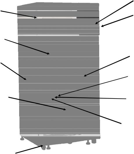
SECTION 2 – EQUIPMENT OVERVIEW
Congratulations! You have just purchased the latest technology in CO2 incubators. Before using the equipment, familiarize yourself with key components of the product and thoroughly read this manual.
Replaceable air intake filter (refrigerated models)
Heated Triple Pane
Outer Glass Door
Left Side
Access Port
Adjustable
Sliding Shelf
(7400-25/33)
Outer Door Drip
Trough
7” Full
Color HMI
Power
Switch
Right side
 CO2 Sample
Port
Right Side
Access Port
RTD
Temperature
Sensor
Infrared CO2
Sensor
Humidity
Sensor (Controlled
Humidity only)
Model 7400-25 shown.
The following incubator models have pre-configured internal shelving and brackets tailored for particular applications used in cell culturing:
7401-25/33 Multi-Tier Shaker Ready CO2 Incubators
7402-25/33 Cell Roller Ready CO2 Incubators
7403-25/33 Shaker / Cell Roller Ready CO2 Incubators
7400 Series Operations Manual |
Rev A 07/25/14 |
Page 10 of 83 |
SECTION 2 – EQUIPMENT OVERVIEW – CONTINUED
Day / Time |
Actual |
Status Bar |
Actual |
|
Temperature |
|
Humidity |
Speaker 
Lockout icon
Parameter
Display
Zones
Set point
Menu
 Settings
Menu
Current screen indicator
Navigation
Pane (indicates menu depth)
Submenu categories
7400 Series Operations Manual |
Rev A 07/25/14 |
Page 11 of 83 |

SECTION 3 - INSTALLATION
Unpacking
Your new unit has been thoroughly packaged to avoid shipping damage. However, the unit should be fully inspected upon arrival before signing for receipt. If the package has visual damage, notes should be made on the freight bill and signed by the delivery company. In the event of concealed damage after the unit is uncrated, keep the carton and packaging material. Call the shipping company within 7 days of receipt, request inspection and retain a copy of the inspection report.
Caron provides full on-site installation services for all models. Our installation services guarantees the proper set-up and startup of all equipment. Please contact the Service Department at 740-373-6809 or service@caronproducts.com for details.
Choosing a Location
This product weighs in excess of 500 pounds. Ensure that sufficient resources are available to safely move the product.
To ensure proper operation, the unit must be located on a firm level surface, capable of supporting approximately 800 pounds. The unit should be located in an 18°C – 25°C ambient area and where there is no direct airflow from heating and cooling ducts as well as out of direct sunlight. Allow four inches of clearance on all sides of the product to allow for connections and airflow.
The unit requires a dedicated electrical connection. Depending on the options purchased with unit a floor drain may be required. Choose a location where these facilities are or can be made available. If a water source, or a drain is not available, contact CARON customer service and ask about our CRYS102 product line or click this web link for information on the product:
http://www.caronproducts.com/65
7400 Series Operations Manual |
Rev A 07/25/14 |
Page 12 of 83 |
Preliminary Cleaning
Your new incubator was thoroughly cleaned prior to leaving the factory. It is recommended however, to disinfect all interior surfaces with a general purpose laboratory cleaning agent prior to using the product. After cleaning, dry all interior components with a sterile cloth as necessary.
Installing the Port Stoppers
The unit has an access port built into each side of the cabinet. The ports are designed to allow customer access for equipment validation or for installation of other equipment inside the chamber. These ports should be sealed with the provided rubber stoppers to allow the incubator to function properly. Install the stoppers provided in the port on each side of the unit.
Installing the Shelves
Models 7400-25 / 33 incubators include sliding perforated stainless steel shelves. Each shelf requires two shelf channels for installation. Prior to installation, take time to consider what the size of the product being placed in the incubator will be and set the shelf spacing accordingly. Additional shelving can be purchased through CARON customer service if necessary.
To install the shelf channels slide on end of the shelf track into the appropriate shelf location in the rear plenum. Hook the front of the shelf track into the corresponding location on either the right or left side front shelf support pilaster. Repeat the process on the opposite side of the incubator.
Shelf capacity: each perforated shelf is capable of supporting a uniformly distributed load of 50 lbs.
The maximum chamber capacity is 500 pounds (stationary). Optional shelving is available for supporting heavy loads such as shakers or cell rollers. Chamber should be empty when being moved.
Do not pull multiple loaded shelves out simultaneously or the chamber may tip.
7400 Series Operations Manual |
Rev A 07/25/14 |
Page 13 of 83 |
Models 7401 and 7403 do not have sliding shelves, but a sliding shelf accessory can be purchased.
Leveling the Unit
Place a level on the middle shelf of the incubator. Adjust the feet until the unit sits level left to right and front to back. Even if the unit is level without adjustment, the leveling feet should still be lowered to avoid the cabinet moving while opening and closing the outer door & prevent a flat spot from forming on the casters.
Connecting the Drain
When using a pressurized water source, failure to connect the unit to a drain could result in facility flooding.
The incubator can have humidity either by an evaporative pan or injecting water. To remove excess water that is not humidified or water that can be spilled when filling the evaporative pan, connect the drain fitting and tubing supplied with the incubator to a local floor drain, minimizing the risk of contamination and corrosion.
The drain line relies on gravity to remove water from the chamber. The drain line must remain below the chamber to drain properly. Kinks or elevations in the drain line above the cabinet drain will not allow the chamber to drain.
If a local floor drain is not available, a variety of accessories are available through CARON customer service. These accessories can also be viewed at www.caronproducts.com
Models 7401-25/33, 7402-25/33 and 7403-25/33 are non-humidified chambers and have a 1/2” plug installed into the drain connection. The drain will be required when a humidity option is purchased with the chamber.
7400 Series Operations Manual |
Rev A 07/25/14 |
Page 14 of 83 |
Fill water pan (also HUMD305, HUMD306)
Use only distilled or deionized water with a resistivity between 50K -CM and 1M -CM and a pH of greater than 6.5. Using water outside this range will void your warranty.
Do not use water that contains chloramines. Chloramines can damage internal rubber gaskets resulting in leaks.
A water pan is used to provide elevated humidity levels inside the incubator. This feature is standard on 7400 models (and optional for the others). Using the handles provided, remove the empty water pan from the bottom of the incubator. Fill with 5 to 6 liters of water. Re-insert water pan back into the incubator.
Connecting a CO2 supply
High concentrations of carbon dioxide can cause asphyxiation. The use of CO2 monitors and alarms is recommended for areas where CO2 can collect.
The CO2 gas supply should be 99% pure and should not contain a siphon tube. Gas pressure to the unit must be regulated to 15-20PSI. Failure to do so could cause tubing to burst.
The CO2 supply should be 99% and not have siphon tubes. CO2 pressure should be regulated to 15-20 psi. CO2 tank regulators REGL101 can be purchased through CARON customer service. Once the cylinder regulator is installed, connect the outlet of the regulator to the hose barb fitting using the tubing and clamps provided. An inline HEPA filter is provided to remove any contaminants in the CO2 gas supply. Check the connections closely for leaks.
7400 Series Operations Manual |
Rev A 07/25/14 |
Page 15 of 83 |
If the unit is equipped with a built in gas guard system GASG302, there will be 2 gas inlets. Each of the inlets should be connected to an individual gas tank as described above.
Connecting Electrical Power
Connect each incubator to a grounded circuit.
Failure to do so could result in electrical shock.
The unit requires a dedicated electrical outlet. See table below for model specific power required and connection.
Model # |
Power Requirements |
Plug Connection |
-1 |
115V, 60Hz, 16A FLA |
NEMA 5-20 |
-2 |
230V, 60Hz, 10A FLA |
NEMA 6-15 |
-3 |
230V, 50Hz, 8A FLA |
CEE 7/7 |
When the required electrical connection is available, plug the provided power cord into the unit and the electrical outlet.
Cell Roller Ready (Models 7402 & 7403)
These models have a cell roller, a reinforced floor, cell roller ramp, and interior outlet. These models were designed to hold a 3, 5 or 7 tier Wheaton R2P cell roller.
Support braces have tracks to guide the cell roller wheels into the incubator. The cell roller ramp has small tabs at the end that fit into an opening at the end of each cell roller support brace.
The ramp is designed to support the weight of the cell roller as it is pushed into the incubator. Once the cell roller is pushed into the incubator, remove the ramp and save it in a convenient place should it need to be reused to remove the cell roller.
Cell Rollers can be heavy and awkward to handle. Ensure that sufficient resources are available to safely move the product.
7400 Series Operations Manual |
Rev A 07/25/14 |
Page 16 of 83 |

SECTION 4 – OPTIONAL ACCESSORY INSTALLATION
Connecting Alarm Contacts (ALRM302)
With the purchase of ALRM302, a set of terminals on the rear of the unit is provided to monitor temperature and humidity (controlled humidity option) alarms.
With the alarm contacts, the terminals provided allow for a NO (normally open) output, a NC (normally closed) and COM (common) connection. In the event of an alarm condition or power failure, the NO contact will close, and the NC contact will open. Once the alarm is cleared, the contacts return to their normal conditions. Insert the appropriate wire into the terminal and tighten down the screw terminal on top of the connector.
Terminal Connection |
Unit off |
Normal |
Alarm |
N/O to C |
Closed |
Open |
Closed |
N/C to C |
Open |
Close |
Open |
7400 Series Operations Manual |
Rev A 07/25/14 |
Page 17 of 83 |
Installing Carboy water system (BOTL301)
Incubators can be purchased with an optional 2.5 gallon carboy water system. The carboy system is preassembled and shipped inside the chamber. The four ¼” bolts required to mount the carboy to the unit will be mounted in the left hand side of the chamber. Remove the carboy assembly from inside the chamber and attach it to the chamber using the ¼” bolts.
¼” Bolts
 (4 total)
Tubing connects/ disconnect to carboy
Attach the preassembled tubing provided with the carboy to the water inlet on the rear of the chamber.
Tubing to water inlet
Fill the carboy with water as described in the “Using the Carboy Water System” section of the manual.
7400 Series Operations Manual |
Rev A 07/25/14 |
Page 18 of 83 |
Connecting to Humidity System (HUMD304, HUMD307)
Use only distilled or deionized water with a resistivity between 50K -CM and 1M -CM and a pH of greater than 6.5. Using water outside this range will void your warranty.
Do not use water that contains chloramines. Chloramines can damage internal rubber gaskets resulting in leaks.
If these water sources are not available contact CARON customer service.
A water inlet fitting on the back of the unit and ¼” black tubing are provided to connect the water supply to the incubator. Connect an appropriate water supply to the fitting. Incoming line pressure should be regulated to not exceed 80 psi.
CRSY102 or BOTL301 are accessories that can be used as a water supplies. If a Condensate Recirculator CRSY102 water recycling system was purchased as a water supply, refer to its user’s manual for proper installation of the water supply.
7400 Series Operations Manual |
Rev A 07/25/14 |
Page 19 of 83 |

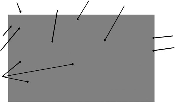
Connecting Analog Outputs (OUTP302, OUTP303)
With the purchase of OUTP302 or OUTP303, the controls are equipped with analog outputs. OUTP302 provides 2 connections for monitoring temperature and humidity or CO2. OUTP303 provides 3 connections for monitoring temperature, humidity and CO2.
Analog outputs are either milliamps (4-20mA) or voltage (0-5V) signal output that represents each of the displayed temperature, humidity or CO2 values. These options can be used for connection to in-house data acquisition, recorder, or alarm system.
Parameter |
Analog Output |
Current |
Corresponding Value |
Temperature |
0 – 5 V |
4-20 mA |
0 – 100 °C |
Humidity |
0 – 5 V |
4-20 mA |
0 – 100 %rh |
CO2 |
0 – 5 V |
4-20 mA |
0 – 100 %CO2 |
Connect shielded wires to the appropriate signal terminals: I(+) for current (mA) or V(+) for voltage (DC). For both current and voltage outputs, COM(-) is common terminal.
|
|
|
|
7400 Series Operations Manual |
Rev A 07/25/14 |
Page 20 of 83 |
|
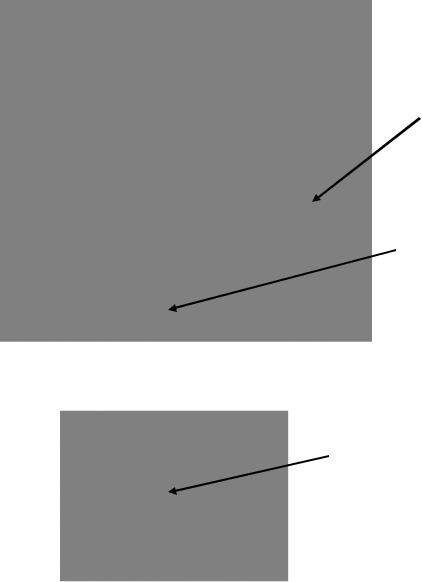
Installing Drain Water Pump (PUMP301)
Pump Outlet to Sink or Floor Drain
Pump Inlet from Chamber Drain
Reservoir with Internal Level
Switch
In applications where a floor drain is not available and a CARON water recycling system CRSY102 is not being used, a drain pump can be purchased to pump any excess condensate from the chamber to a local sink or drain. The pump is located near the middle of the back of the chamber. Connect the supplied tubing from the pump to the sink / drain. The tubing may be run vertically into a ceiling but should not exceed 15 feet height. The pump is equipped with a small reservoir on the bottom of the pump with an internal level switch that will automatically turn the pump ON when it is full to drain the water out of the reservoir and into a floor or sink drain.
7400 Series Operations Manual |
Rev A 07/25/14 |
Page 21 of 83 |
SECTION 5 – OPERATION
With the chamber properly installed and the appropriate utilities connected, the power switch on the right side top wrap can be turned on. Within a few minutes, the temperature and humidity will begin to approach set-points. Here is an overview of the home screen.
Day / Time |
Actual |
Status Bar |
Actual |
|
Humidity |
||
|
Temperature |
|
|
|
|
|
Speaker |
Setpoint |
|
Menu |
Lockout |
Settings |
icon |
Menu |
Parameter |
|
Display |
|
Zones |
|
Main screen with HUMD304, HUMD307 option
7400 Series Operations Manual |
Rev A 07/25/14 |
Page 22 of 83 |

Using the Keypad
This control system uses a numeric keypad to enter all parameter values. Similar to a calculator, this allows quick and precise entry of values. When any numeric value button is pressed, the keypad display will pop up over the current display.
Range of variable |
Parameter Description |
|
Header |
||
|
Keypad
Display 
Escape
Clear
Negative sign
Enter
Decimal
The Parameter Description Header tells what parameter is being changed.
The Keypad Display shows allowable values of the parameter being changed (initially) and displays the entered value (when a button is pressed).
The Escape “Esc” button aborts the entry and returns to the previous screen without changing the value. The Clear “Clr” button erases the value that you have entered. After you have entered the value that you want, pressing the Enter “Ent” button and the new value will take effect. This also closes the keypad window. Other keypad buttons include a decimal point button and negative button.
If an invalid numeric button is pressed such that it would create an entry above the parameter’s range, the entered number will not display. For example, if the temperature set point range is 5.0 to 70.0, pressing ‘8’ followed by an ‘0’, only the ‘8’ will display.
If an invalid entry is made with an entry below the range (such as a ‘4’ followed by the ‘Ent’ button), then the entry will clear and the range will be re-displayed.
7400 Series Operations Manual |
Rev A 07/25/14 |
Page 23 of 83 |
Learning the screen saver
To ensure long product life, the touchscreen display will automatically enter screen saver mode after 15 minutes. At this time, the screen will be completely blank (ie. black). The illuminated Caron logo (see Equipment Overview section) shows that the unit is powered on and functioning. To wake-up the touchscreen, simply press anywhere on the touchscreen and the main screen will display. If the unit has an alarm condition, the touchscreen will not go into screen saver mode. If an alarm condition occurs while in screen saver mode, the display will automatically wake up and display the alarm.
7400 Series Operations Manual |
Rev A 07/25/14 |
Page 24 of 83 |

Changing the Temperature Set-point
The steps below walk through an example of changing the temperature set point from 37.0 °C to 20.0 °C. This example shows optional humidity control.
Here is the display of the home screen.
Actual |
Setpoint Button |
|
|
Temperature |
|
To set the temperature set-point, press the  (Setpoint) button on the right side of the screen.
Temperature
Setpoint Button 
Once the Setpoint screen appears, press the  (Temperature Setpoint) button. (In this example the temperature set point initially has a value of ’37.0’; this will vary with different initial set point values.)
7400 Series Operations Manual |
Rev A 07/25/14 |
Page 25 of 83 |
 Loading...