

caron 6010, 6030, 6031, 6032, 6012 Operation Manual
...
CARON 6000 SERIES
ENVIRONMENTAL TEST CHAMBERS
MODELS 6010, 6011, 6012, 6030, 6031, & 6032
OPERATIONS MANUAL

TABLE OF CONTENTS
SE CTION
INTRODUCTION
Symbols and Warnings......................................................... 3
.............................................................. 3
P AG E S
SPECIFICATIONS ........................................................... 5
INSTALLATION ...............................................................
Chamber Location ................................................................ 7
Drain Connection ................................................................. . 8
Power ................................................................................... 8
OPERATION
CONTROLLERS
Temperature Deviation Alarm ............................................. 12
.................................................................. 10
..................................................................... . 12
7
OPTIONS . ..................................................................... 13
Humidity System & Controller ............................................. 13
Humidity Controller Calibration ........................................... 14
Humidity Water Inlet ........................................................... 14
Diurnal Lighting System...................................................... 15
Heatless Dryer Package ..................................................... 16
Dryer Package Installation ....................................... 16
Dryer Package Testing & Adjustments .................... 17
Circular Chart Recorder...................................................... 18
Setup, Installation .................................................... 18
Routine Maintenance ............................................... 21
Contact Closure Timer System ........................................... 22
Condensate Recirculating System...................................... 23
Remote Alarm Contact ....................................................... 25
Product Temperature Safety............................................... 25
Computer Communications ................................................ 12
Defrost Package............................................................................ 26
MAINTENANCE
TROUBLESHOOTING
APPENDIX A – Watlow 96
General Controller Operation.............................................. 30
Light & Contact Timer, Communications ............................ 31
APPENDIX B – Watlow SD
APPENDIX C – 230 V Optional
Light & Contact Timer ......................................................... 33
APPENDIX D – Declaration of
....................................................................... 27
GUIDE
..............................................
Controller
Controller
Unit
Conformance
...............................
..............................
.................................. 33
................ 34
29
30
32
6000 SERIES MANUAL_U.doc 12-12-07 2
INTRODUCTION
The CARON 6010 & 6030 series Environmental Test Chambers provide multiple capabilities to
create repeatable environmental conditions for numerous applications including:
Product shelf life
•
Stability and package testing
•
Light exposure and temperature evaluation studies
•
Electronic component burn-in
•
TAPPI testing
•
Photostability
•
Plant growth
•
Insect rearing
•
These chambers utilize environmentally friendly HFC refrigerant and CFC-Free insulation, and is
designed to meet NEC, UL and CSA standards for safety and performance.
Controlling the chamber temperature requires the ability to heat and cool. Heating of the chamber
is achieved by duct heaters, and cooling is achieved by a direct expansion/vapor compression
refrigeration heat exchanger mounted in the duct, combined with horizontal airflow pattern which
creates better air uniformity, and temperature control.
A bi-modal controller (single input - dual output) is necessary for proper control of the system that
can drive the process variable in either direction. The refrigeration system uses a single
condensing unit that will allow independent cooling and dehumidification. This insures continuous,
safe and reliable operation of the compressor even when no cooling is required. This also
prevents the compressor from rapid cycling “on” and “off” which shortens the compressor life.
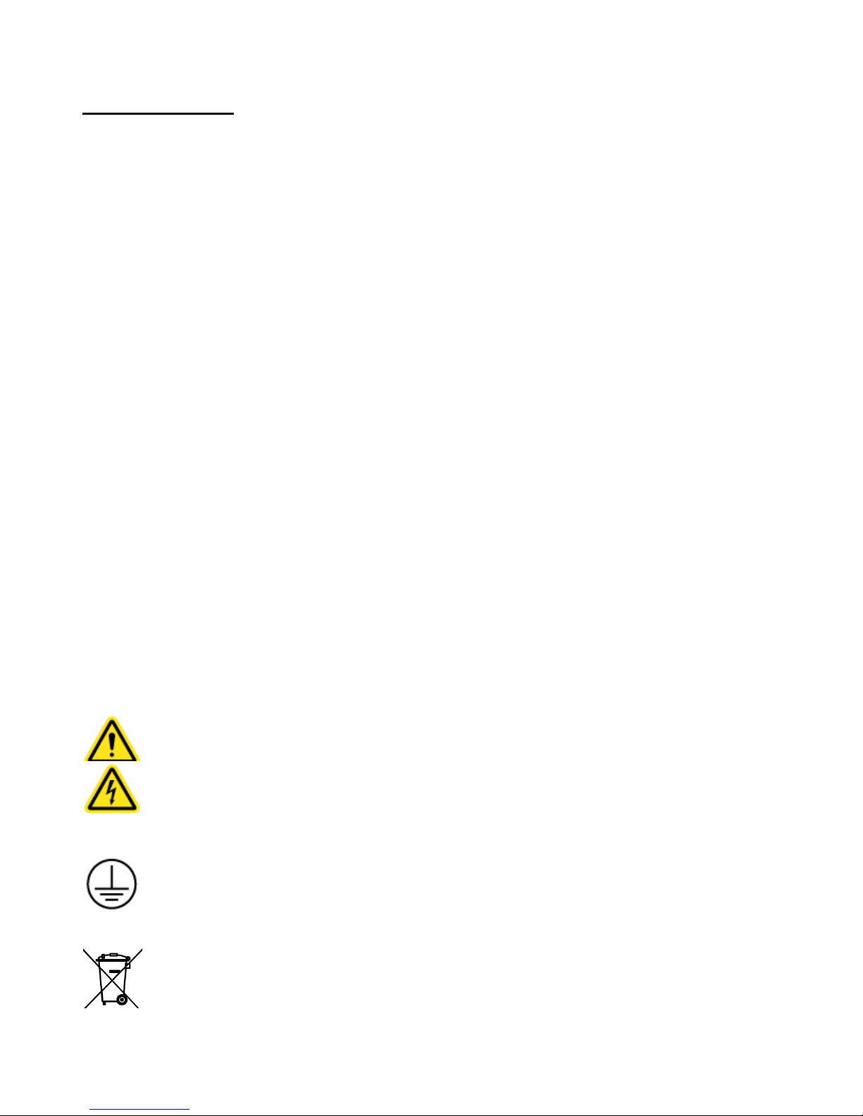
SYMBOLS AND WARNINGS
Warning of hazardous area
Warning of dangerous electric voltage
Earth (ground) protective conductor
Local government may require proper electrical component disposal

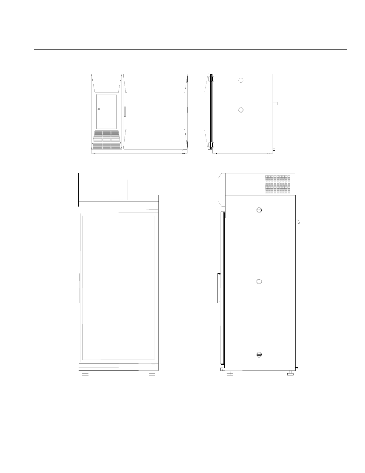
CHAMBER CONSTRUCTION
The chamber is a custom designed sheet metal package. Exterior metal is Cold Rolled Steel
(CRS) with a powder coat finish for corrosion resistance. The chamber interior is constructed from
304 stainless steel, with all joints seam welded. The chamber face connecting the interior to the
exterior is magnetic stainless steel providing a sealing surface for the magnetic gasketed exterior
door as well as improved corrosion resistance. The control panel housing is constructed from
aluminum with a powder coat finish. The chamber is insulated on all sides with fiberglass
insulation rated at 70°C.
SHELF CONSTRUCTION (STANDARD)
The chamber shelves are polished, 304 stainless steel wire formed.
REFRIGERATION SYSTEM
A bi-modal refrigeration system allows for independent heating and cooling. This system is now
used to replace the less sophisticated type of refrigeration system which used heaters to buck
against the refrigeration system and assist in temperature control. The new design allows the
chamber to respond faster and controls the chamber more efficiently at a constant temperature.
CONTROL SYSTEM
The control system is comprised of a single channel, dual output controller. On/off outputs are
used to drive heaters and cooling solenoids.
SAFETIES
The CARON 6000 Series has a triple redundancy safety system. A temperature alarm in the
temperature controller sounds an alarm to alert the end user to the condition. A thermal snap
disk, high limit and a thermal fuse are provided to prevent run-away heating of the unit. The
compressor and blower motors are both protected by thermal overloads. The Condenser fan
motor is impedance protected.

MODEL 6010 SPECIFICATIONS
Temperature Range without lights 5°C to 70°C
Temperature Range with lights 10°C to 70°C
Temperature Control
Temperature Uniformity
Humidity 20 to 98% RH
Humidity Control ± 3%
Interior Dimensions 23”W x 25.8”D x 29.8”H
Exterior Dimensions 43.4”W x 30.6”D x 36”H
Work Space 10 cu.ft. (283.2 liters)
Shelves
Number of shelves 4 Stainless Steel, Wire Rod Standard
Shelf Spacing 1.5” on center (15 positions)
Shelf Size Each Shelf: 22.8”W x 25.4”D
Shelf Area 4ft.2 each, 16ft.2 total
Materials / Finishes:
Interior Chamber - all Stainless Steel
Exterior Chamber - Cold Rolled Steel and
Magnetic Stainless Steel, Powder
Exterior Door Aluminum, Powder Coat Finish
Feet Adjustable leveling pads
Electrical 115V/20A/60Hz (standard, 220V optional)
Shipping Weight 400 lbs.
Display Resolution:
Temperature 0.1°C
Relative Humidity 1% RH
± 0.1°C
± 0.3°C Relative
∗
(58cm x 65.5cm x 75.7cm)
(110cm x 77.7cm x 91.4cm)
(57.9cm x 64.5cm)
Interior door - Tempered glass
Coat Finish
∗
RH
levels limited by 4°C minimum dewpoint
Specifications were established at 20°C with 50% RH ambient conditions.
Chamber
ambient
conditions
2 0 °
C to
25 °
C.
Exceeding
2 5 °
C
can
result
in
For help with operation of the unit, call Customer Service at 1-740-373-6809.
chamber
failure.

MODEL 6030 SPECIFICATIONS
Temperature Range without lights 5°C to 70°C
Temperature Range with lights* 10°C to 70°C
Temperature Control
Temperature Uniformity
Relative Humidity* 20 to 98% RH
Humidity Control* ± 2%
Interior Dimensions 30”W x 27.5”D x 63.5”H
Exterior Dimensions 36”W x 39”D x 90”H
Work Space 30 cu.Ft. (850 liters)
Shelves
Number of shelves 5 Stainless Steel, Wire Rod Standard
Shelf Spacing 1.5” on center (37 positions)
Shelf Size Each Shelf: 29.25”W x 26.5”D
Shelf Area 5.4ft.2 each, 26.9ft.2 total
Materials / Finishes:
Interior Stainless Steel
Exterior Metal with powder coated finish
Feet Adjustable leveling pads
Electrical 115V/25A/60Hz 1Ph. (standard, 220V optional)
Shipping Weight 750 lb. (340kgs)
± 0.1°C
± 0.3°C
**
(76.2cm x 69.9cm x 161.3cm)
(91.4cm x 99.1cm x 228.6cm)
(74.3cm x 67.3cm)
*Optional items
**RH levels limited by 4°C minimum dewpoint
Specifications were established at 20°C with 50% RH ambient conditions.
Chamber
ambient
conditions
2 0 °
C to
25 °
C.
Exceeding
2 5 °
C
can
result
in
For help with operation of the unit, call Customer Service at 1-740-373-6809.
chamber
failure.
INSTALLATION
Unpacking
This product has been completely tested, cleaned and packed for shipment. Carefully remove all
packing material. Please examine the chamber completely. Should any damage be found, notify
the delivering carrier immediately.
Report any shortages to Customer Service at 1-740-373-6809.
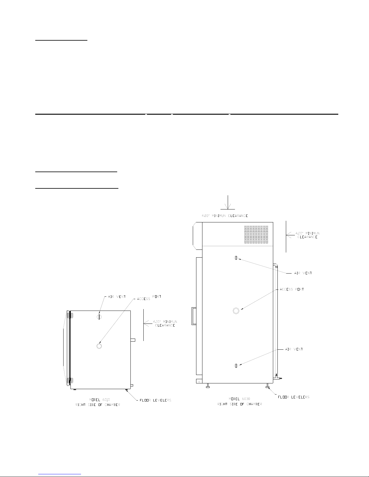
Chamber Location
Chamber ambient conditions 20
C to 25
°
C. Exceeding 25
°
C can result in chamber failure.
°
The chamber must be located in a dry, clean, and level area. Allow a 4” clearance from the back
and top of the chamber for proper air circulation and ease of installation. Locate the chamber in
an area out of direct sunlight and away from heating and cooling ducts. The 6010 & 6030
chambers can exhaust 2500 BTU/hr (730 W) and 4000 BTU/hr (1170 W) respectively into the
surroundings. The figure below shows a side view of the chamber with air vent and access port
locations.
Models
6030,
6031,
603 2 : Tilt the unit ½ of a level’s bubble toward the back for proper water
drainage
Models
6010,
6011,
6012: Unit should be completely level for proper water drainage
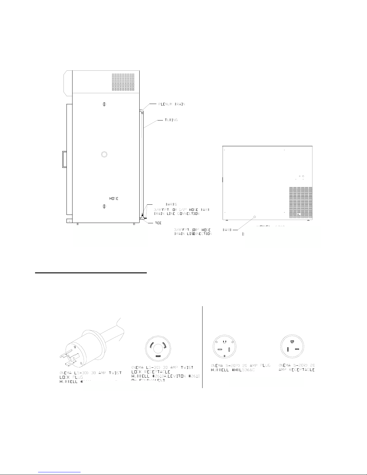
Drain connection
Connect a 3/8” NPT drain line to the drain connection located on the lower back side of the chamber. The figure
below shows the drain connection on the back of the chamber. For proper operation the drain hose should not be
kinked or bent. It should run down from the chamber and go into an open floor drain.
Models 6030, 6031, 6032
Right side of chamber
Models 6010, 6011, 6012
Back side of chamber
Power
PLEASE READ CAREFULLY!
For personal safety, this chamber must be properly grounded.
The Power Cord of this chamber is equipped with a grounded plug which mates with a
corresponding outlet to minimize the possibility of electrical shock from the chamber. CARON
recommends that the chamber have a dedicated wall outlet.
Models 6010, 6011, 6012
Models 6030, 6031, 6032
INSTALLATION cont.
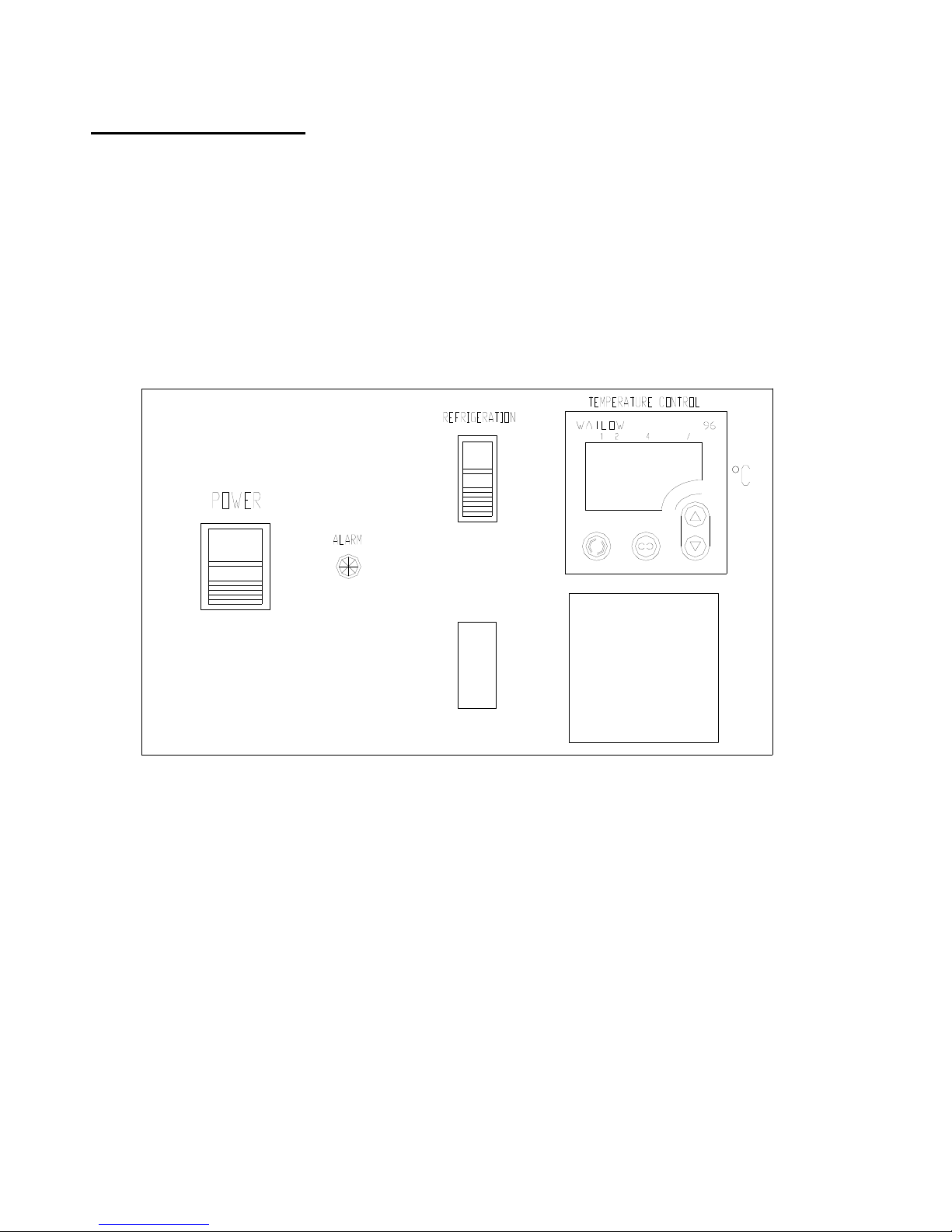
Control System
The control system is comprised of a 1/16 DIN temperature controller. The drawing below shows
the control panel (exact controller may vary). The display panel consists of a power switch,
refrigeration switch, and a temperature controller. The temperature controller’s unit is degrees
Celsius (°C). Refer to the figure below for the layout for the indicator lights as detailed below.
See appendix for controller operating instructions.
CONTROL PANEL
2 0
.
OPERATION
1. Connect the drain lines, and power cord as instructed in the INSTALLATION section of this
manual. (See Appendix C for additional drain connections. 6030 only)
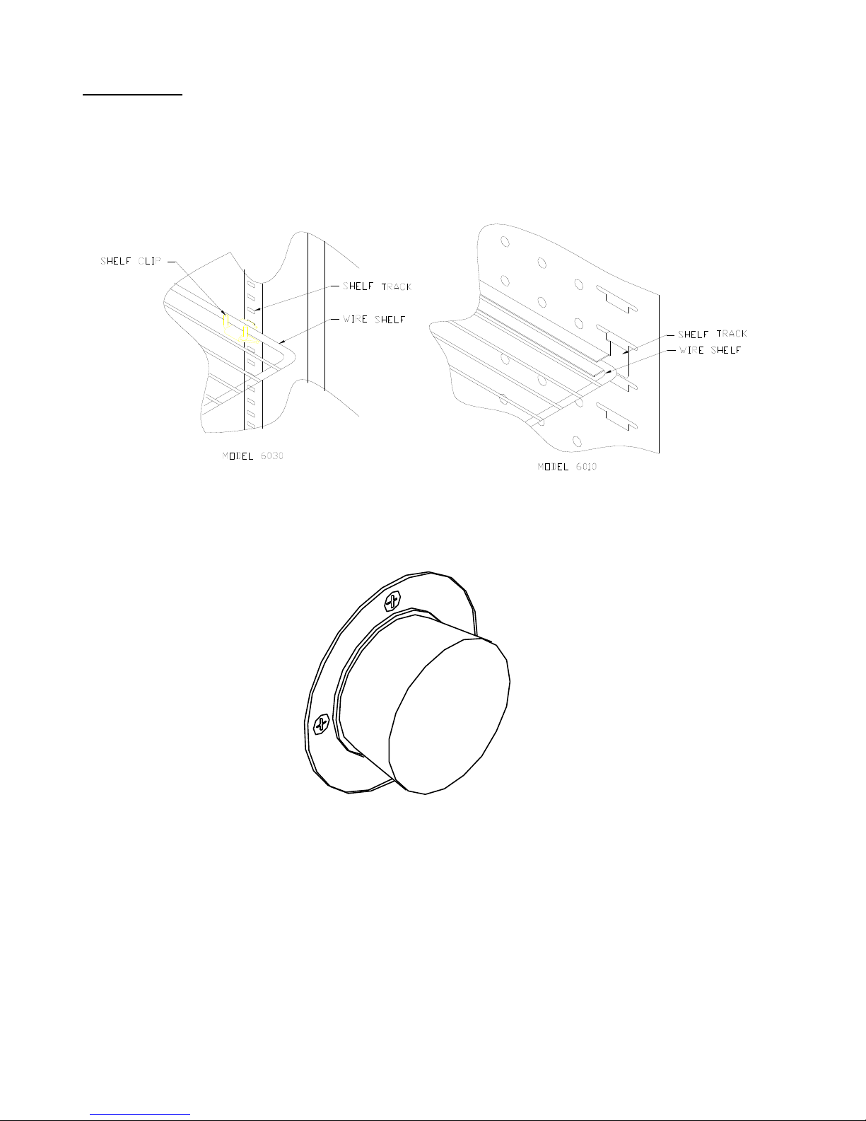
2. Insert all shelf clips, and shelves. Check to see if they are properly installed.
3. Close the chamber door.
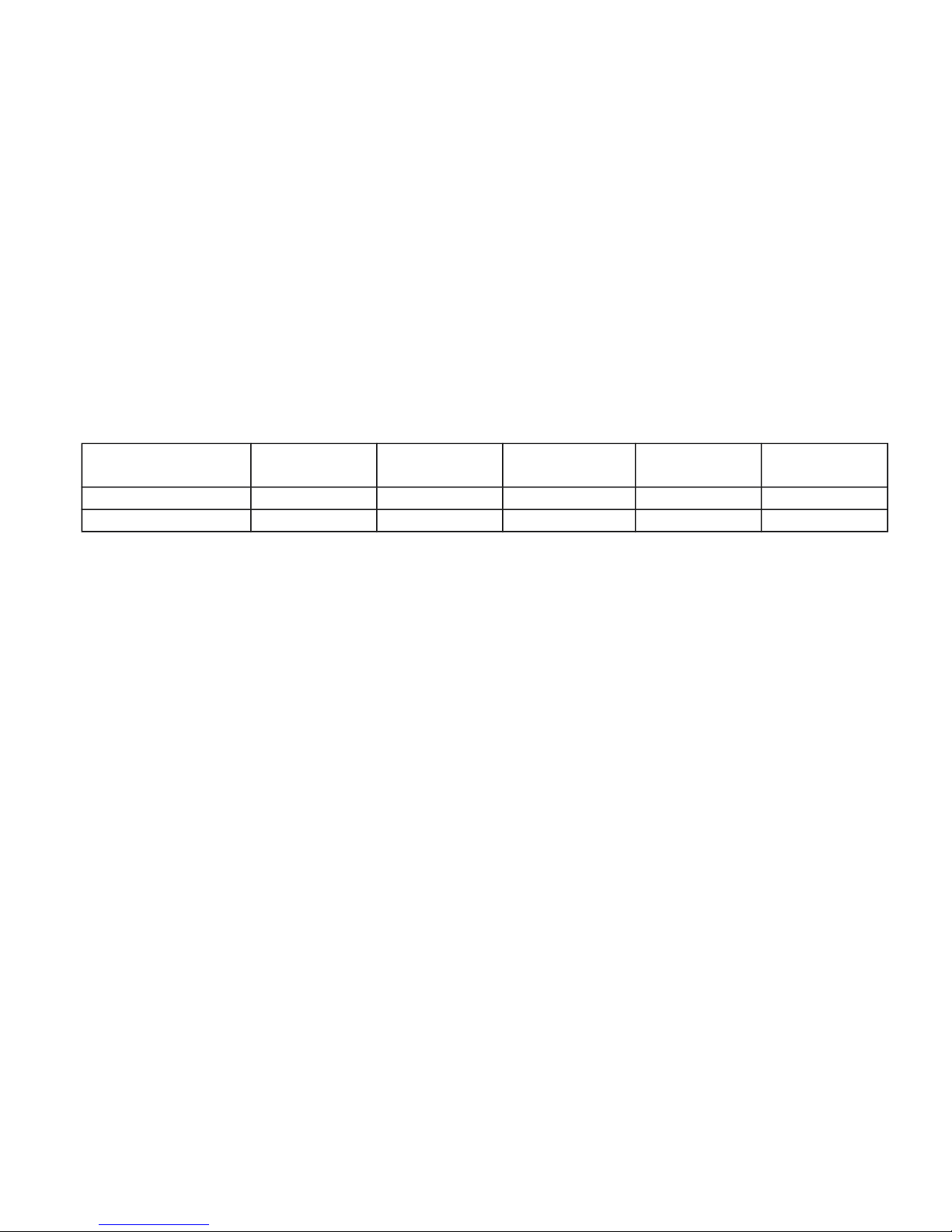
4. Install rubber stopper in access port on right side of cabinet.
5. Turn on power switch located on the control panel. This switch activates the heating unit and
temperature controller. The temperature controller will sound an alarm. The temperature alarm
will automatically reset after a few seconds.
6. *Turn on the refrigeration switch when operating at setpoints below 35°C. This switch
activates the refrigeration system.
7. Set the temperature controller to the desired setpoint. (See appendix if necessary).
8. Turn on the humidity switch. This switch activates the humidity system and the humidity
controller. (with humidity option only). Set the humidity controller to the desired setpoint. (See
appendix if necessary).
During normal refrigeration operation, a soft “clicking” sound can be heard. This sound is the
result of the solenoid control valves switching in the refrigeration system.
Chamber Loading
Air circulates through the chamber to maintain uniform conditions. When loading (putting product
into) the chamber, position samples so air can flow freely throughout the chamber. For best
temperature & humidity uniformity, keep samples away from surfaces as listed in table below. Do
not put product on the floor.
Between
Model Ceiling Back wall Side walls Front / door
shelves
6010, 6011, 6012 2 in (5 cm) 2 in (5 cm) 4.5 in (11 cm) 2 in (5 cm) 2 in (5 cm)
6030, 6031, 6032 6 in (15 cm) 6 in (15 cm) 3.5 in (9 cm) 3.5 in (9 cm) 3.5 in (9 cm)
 Loading...