

Page 1
Installation and Maintenance Manual IM 902
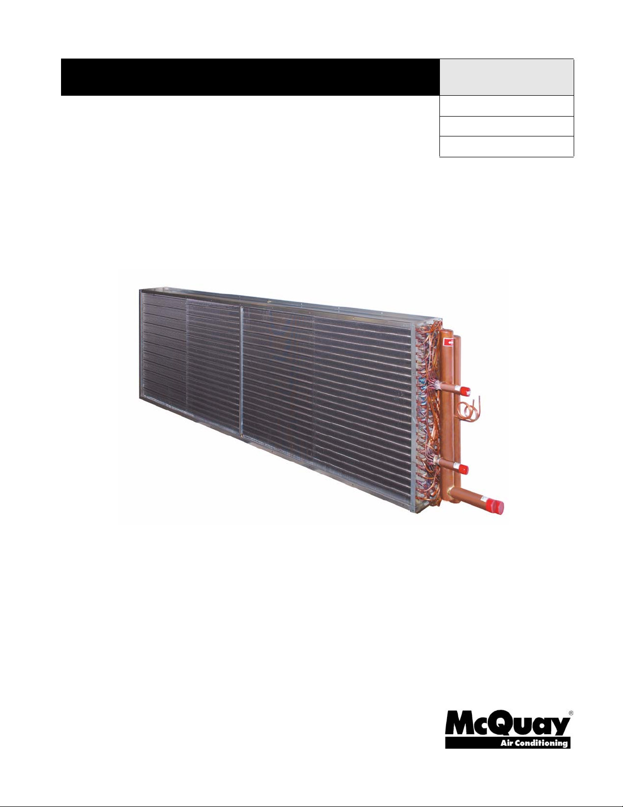
McQuay Direct Expansion (DX) Cooling
Coils
Types EN, EF, ER, EJ, EK
Group: Applied Air
Part Number: IM 902
Date: February 2008
© 2008 McQuay International
Page 2

Contents
Introduction .............................................................. 3
General Information................................................ 3
Hazard Identification Information............................ 3
Receiving Instructions ............................................ 3
Coil Types............................................................... 3
Model EN............................................................ 3
Model EF ............................................................ 3
Model ER............................................................ 3
Model EJ............................................................. 3
Model EK ............................................................ 3
Nomenclature......................................................... 4
Installation ................................................................ 5
Mounting ................................................................ 5
Installation.............................................................. 5
Operation and Maintenance.................................... 7
Operation ............................................................... 7
General .............................................................. 7
Maintenance .......................................................... 7
General .............................................................. 7
Page 3
Introduction
Introduction
General Information
Guidelines for the installation, operation and maintenance of
McQuay direct expansion (DX) cooling coils have been
provided to help insure proper performance of the coils and
their longevity. These are general guidelines that may have to
be tailored to meet the specific requirements of any one job.
As always, an experienced installation company or fully
trained individual should perform the installation and
maintenance of any coil. Protective equipment such as safety
glasses, steel toe boots and gloves are recommended during
the installation and routine maintenance of the coil.
Hazard Identification Information
DANGER
Dangers indicate a hazardous situation which will result in
death or serious injury if not avoided.
WARNING
Warnings indicate potentially hazardous situations, which can
result in property damage, severe personal injury, or death if
not avoided.
3 Damaged and/or missing items should be noted on the
carrier's freight bill and signed by the driver.
4 For additional assistance, contact your local McQuay sales
representative.
Coil Types
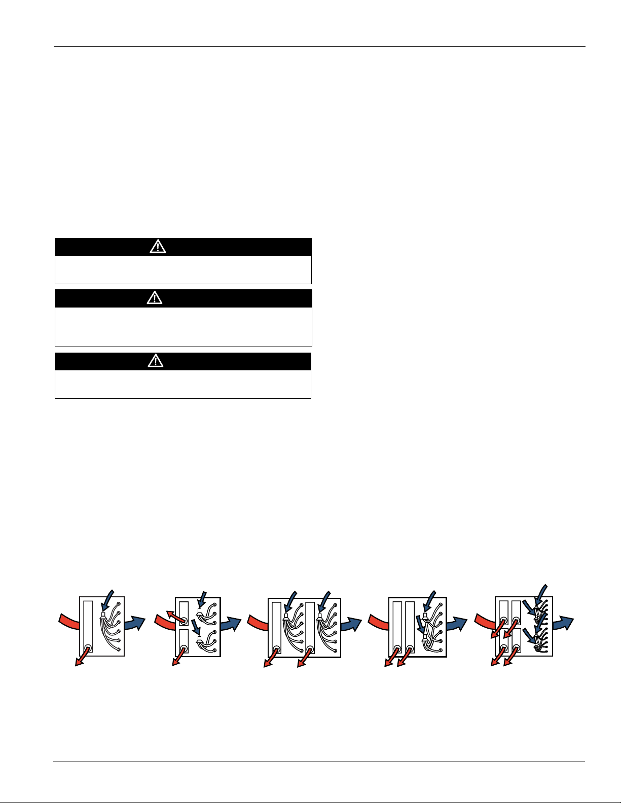
Model EN
This evaporator coil is used for applications where capacity
control is not required. Single or multiple distributors are
available depending on the number of circuits required. Model
EN (Figure 1) evaporators utilize dual suction connections
when multiple distributors are used.
Model EF
Face control (model EF - Figure 1) is another evaporator coil
option offered. Face control is the simplest form of capacity
control. These coils are normally furnished with two
distributors and two suction connections offering 50% capacity
reduction capabilities.
Model ER
CAUTION
Cautions indicate potentially hazardous situations, which can
result in personal injury or equipment damage if not avoided.
Receiving Instructions
1 All McQuay coils are factory tested at 315 psig minimum
air pressure while submersed in water, inspected, and
carefully packaged.
2 Damage to the coils can occur after they have left the
factory. Therefore, the coils should be inspected for
shipping damage upon receipt. The freight bill should also
be checked against items received for complete delivery.
Figure 1: Evaporator Coil Types
McQuay offers a row control option (model ER - Figure 1) for
six row evaporator coils. These coils are split into two rows
and four rows that offer approximately a 50% capacity
reduction.
Model EJ
These evaporator coils (model EJ - Figure 1) come with
interlaced circuiting. This form of capacity control utilizes two
distributors with each feeding every other tube in the first row
of the coil. Each distributor has a separate suction connection.
Model EK
For applications that require face control and interlaced
circuits, we offer evaporator model EK (Figure 1). Interlaced
face control utilizes four distributors and four suction
connections.
EN
Normal
Rows 2, 3, 4, 5
6, 8, 10, 12
McQuay IM 902 3
EF
Face Control
Rows 2, 3, 4, 5
6, 8, 10, 12
ER
Row Control
Rows 6
2 Distributors
EJ
Interlaced
Rows 3, 4, 6, 8
2 Distributors
EK
Interlaced
Face Control
Rows 4, 8
4 Distributors
Page 4

Introduction
Nomenclature
5 E N 14 06 C 24.00 144.00x
Tube O.D.
3=3/8"
4=1/2"
5=5/8"
Coil Type
E = Evaporator
Circuiting
N = Normal
F = Face Control
R = Row Control
J = Interlaced
K = Interlaced Face Control
Finned Length (inches)
Finned Height (inches)
Fin Design
A - flat (AI, Cu)
B - corrugated (AI, Cu)
C - sine wave (AI, Cu)
F - flat (SS, CS)
Rows Deep
Fins Per Inch
4 McQuay IM 902
Page 5
Installation
Installation
Mounting
Position the coil such that the suction header is at the entering
airside of the coil and the distributor tubes are at the leaving
airside of the coil. This orientation provides counter flow heat
exchange that is required for proper coil performance.
The suction connection is located at the bottom of the coil
when properly installed (see Figure 1 on page 3).
Installation
CAUTION
Sharp edges on sheet metal and fasteners can cause
personal injury. This equipment must be installed, operated,
and serviced only by an experienced installation company and
fully trained personnel.
Protective equipment such as safety glasses, steel toe boots
and gloves are recommended during the installation and
routine maintenance of the coil.
CAUTION
Failure to properly install the coil can result in irreparable
damage to the coil as well as other components in the system.
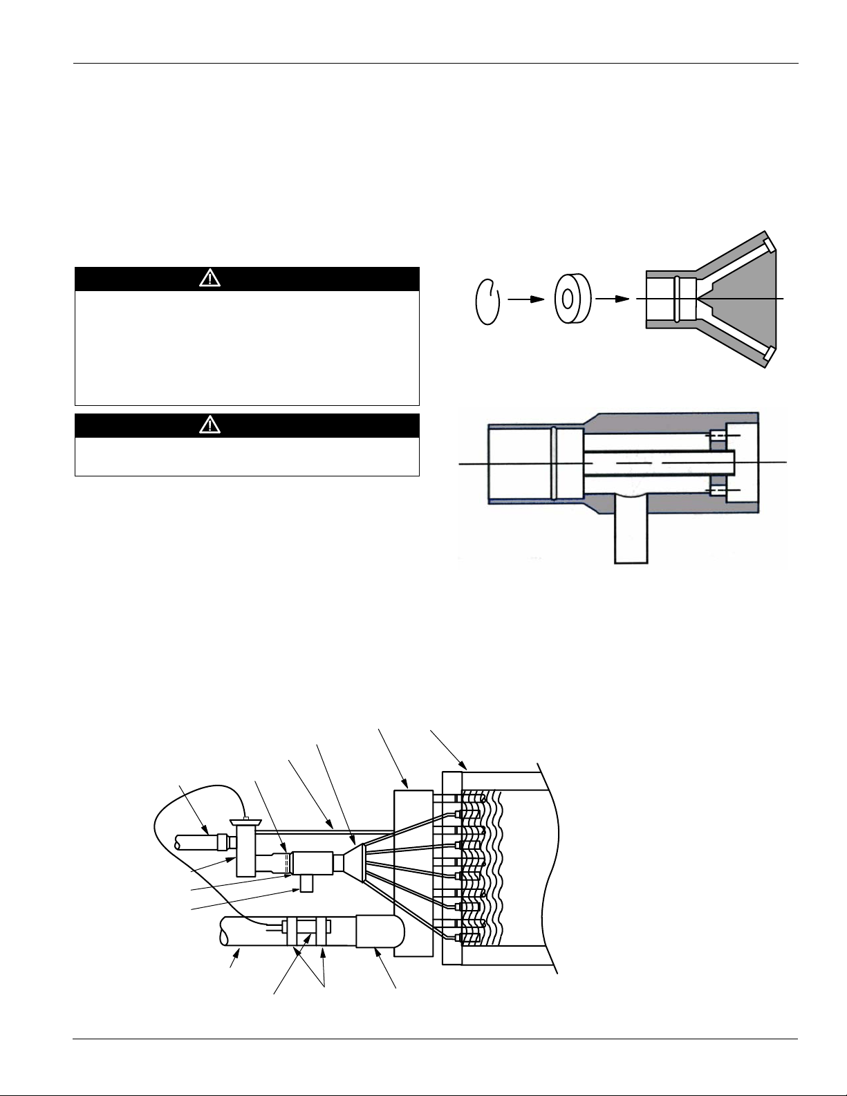
(Figure 2). If a hot gas bypass kit was ordered with the coil,
the nozzle that is in the distributor will need to be relocated
into the hot gas bypass assembly (Figure 3).
4 All field brazing and welding should be performed using
high quality materials and an inert gas purge (such as
nitrogen) to reduce oxidation of the internal surface of the
coil.
Figure 2: Distributor
Retainer
Ring
Figure 3: Hot Gas Bypass Kit
Nozzle
Distributor
If you are unsure about any portion of the installation, contact
your local steam specialist for assistance.
1 Carefully remove the coil from the shipping package to
avoid damage to the finned area. Damaged fins can be
straightened using an appropriate fin comb.
2 Proper clearance should be maintained between the coil
and other structures such as the fan, filter racks, transition
areas, etc.
3 Inspect the refrigerant distributor and verify that the nozzle
is in place. The nozzle is generally held in place by a
retaining ring or it is an integral part of the distributor itself
Figure 4: Hot Gas Bypass Kit Installed
Suction Header
Distributor
Equalizer Line
Liquid Line
Expansion Valve
Hot Gas By-Pass
Hot Gas Side Port
Nozzle
5 If a hot gas bypass kit was ordered with the coil, install it
now (refer to Figure 4 for a general installation diagram).
Complete installation instructions are in the box that
contains the hot gas bypass kit. Align the side port with the
hot gas line prior to brazing into place (Figure 4).
Coil
Suction Line
Remote Sensing Bulb
McQuay IM 902 5
Straps Suction Connection
Page 6

Installation
6 Connect the suction line and suction connection (Figure 4
on page 5).
7 Install the expansion valve (Figure 4 on page 5). Follow the
expansion valve manufacturer’s recommendations for
installation to avoid damaging the valve. If the valve is
externally equalized, use a tubing cutter to cut off the
plugged end of the factory installed equalizer line. Next,
use a de-burring tool to remove any loose metal from the
equalizer line (Figure 4 on page 5) and attach it to the
expansion valve. If the valve is internally equalized, the
factory installed equalizer line can be left as is or it can be
cut back and sealed.
8 The expansion valve’s remote sensing bulb (Figure 4 on
page 5) should be securely strapped to the horizontal run of
the suction line at the 3 or 9 o’clock position and insulated.
9 Connect the liquid line (Figure 4 on page 5) to the
expansion valve. Pressurize the coil, expansion valve
assembly and suction connection to 100 psig with dry
nitrogen or other suitable gas. The coil should be left
pressurized for a minimum of 10 minutes.
10 If the coil holds pressure, the hook-up can be considered
leak free. If the pressure drops by 5 psi or less, repressurize the coil and wait another 10 minutes. If the
pressure drops again, there are more than likely one or
more small leaks, which should be located and repaired.
Pressure losses greater than 5 psi would indicate a larger
leak, which should be isolated and repaired. Be sure to
check valves and fittings as potential sites for leakage or
bleed. If the coil is found to be leaking, contact your local
McQuay coil representative.
Note: Unauthorized repair of the coil may void the coil’s
warranty (see the McQuay warranty policy on back
cover).
11 Use a vacuum pump to evacuate the coil and any
interconnecting piping that has been open to atmosphere.
Measure the vacuum in the piping using a micron gauge
located as far from the pump as possible (the vacuum at the
pump will be greater than the rest of the system). Evacuate
the coil to 500 microns or less then close the valve between
the pump and the system. If the vacuum holds to 500
microns or less for one minute, the system is ready to be
charged or refrigerant pumped down in another portion of
the system can be opened to the coil. A steady rise in
microns would indicate that moisture is still present and
that the coil should be further vacuumed until the moisture
has been removed.
12 Failure to obtain a high vacuum is indicative of a great deal
of moisture or a small leak. Break the vacuum with a
charge of dry nitrogen or other suitable gas and recheck for
leaks (soapy water works well). If no leaks are found,
continue vacuuming the coil until the desired vacuum is
reached.
13 All field piping must be self-supporting.
6 McQuay IM 902
Page 7
Operation and Maintenance
Operation and Maintenance
Operation
General
1 Proper air distribution is vital to coil performance. Airflow
anywhere on the coil face should not vary by more than
20%.
2 The drain pan and associated piping (drain line and trap)
should be installed so that there is no standing water in the
drain pan and that no blow-through occurs.
3 Air velocities should be maintained between 200-550 feet
per minute.
Maintenance
DANGER
Follow the manufacturer’s guidelines for lockout/tagout and
disconnect all power to the unit before performing maintenance.
Contact with high voltage power will cause electrical shock,
resulting in severe personal injury or death.
WARNING
Moving parts, high pressure, and/or high temperature fluids can
cause serious personal injury.
General
1 Filters should be inspected on a regular basis and changed
as needed. Maintaining clean filters is a cost effective way
to help maintain maximum coil performance and service
life.
2 Periodic inspection of the coil for signs of corrosion and/or
leaks is recommended. Repair and replacement of the coil
and the connecting piping, valves, etc., should be
performed as needed by a qualified individual(s).
3 Should the coil surface need cleaning, caution should be
exercised in selecting the cleaning solution as well as the
cleaning equipment. Improper selection can result in
damage to the coil and/or health hazards.
4 Suggested cleaning instructions:
a When handling strong chemicals, be sure to wear
chemical impervious gloves, apron, and splash goggles.
b Acti-Brite (AB-1) is the recommended cleaning
solution. Contact your local McQuay Parts Distributor.
c Determine required dilution for the specific application.
It is recommended to start with a dilution ratio of 10:1
and increase concentration until the desired results are
achieved.
d As with mixing all acids, place the desired amount of
water into the tank and then add the chemicals.
e Turn off fans and allow hot coils to cool before
applying.
f Using plain water, wet both the coil as well as the area
surrounding the equipment. Wetting the coil with water
aids in product penetration and performance.
g Apply properly diluted product to coil surface.
Whenever possible, apply solution from the outlet side
of the coil. Allow solution to remain on surface,
normally 5-10 minutes. Do not allow solution to dry on
the coil.
CAUTION
Carefully read and follow the manufacturer's recommendations
before using any cleaning fluid.
Note: In extreme cases, application may have to be
repeated to achieve desired results.
h If foaming does not occur, check for extreme grease
buildup which will slow cleaning process. Foaming may
not occur if coil is coated or painted.
i Rinse coils, tools, and surrounding area thoroughly after
the coil cleaning.
5 Clean the coil from the leaving airside so that foreign
material will be washed out of the coil rather than pushed
further in.
6 Periodic inspection of the coil for signs of corrosion and for
leaks is recommended. Small leaks can be detected using a
Halide torch. Repair and replacement of the coil and the
connecting piping, valves, etc., should be performed as
needed by a qualified individual.
7 The use of filter-dryers in the system piping is
recommended along with a sight glass that has a moisture
indicator. Replace the filter dryer(s) as needed.
Note: Refrigerant conversions are beyond the scope of this
manual and should only be performed by qualified
parties.
McQuay IM 902 7
Page 8

McQuay Training and Development
Now that you have made an investment in modern, efficient McQuay equipment, its care should be a high priority.
For training information on all McQuay HVAC products, please visit us at www.mcquay.com and click on training, or
call 540-248-9646 and ask for the Training Department.
Warranty
All McQuay equipment is sold pursuant to its standard terms and conditions of sale, including Limited Product
Warranty. Consult your local McQuay Representative for warranty details. Refer to Form 933-43285Y. To find your
local McQuay Representative, go to www.mcquay.com.
This document contains the most current product information as of this printing. For the most up-to-date product
information, please go to www.mcquay.com.
© 2008 McQuay International • www.mcquay.com • 800-432-1342
 Loading...