


 Loading...
Carl Zeiss Sonnar-Superachromat 5,6-250 CFi, Sonnar 5,6-250 CFi, Sonnar 4-180 CFi, Sonnar 4-150 CFi, Makro-Planar 4-120 CFi Service Manual
...Carl Zeiss |
Contents List |
|
|
CB/CFE/CFi Service Manual
00:General Information
01: |
Planar |
2,8/80 |
CB |
02: |
Tessar |
4,8/160 |
CB |
03: |
Distagon |
3,5/60 |
CB |
04: |
Makro-Planar |
4/120 |
CB |
05: |
Planar |
2,8/80 |
CFE |
06: |
Distagon |
4/40 |
CFE |
07: |
Tele-Superachromat |
5,6/350 |
CFE |
08: |
F-Distagon |
3,5/30 |
CFi |
09: |
Distagon |
4/50 |
CFi |
10: |
Planar |
3,5/100 |
CFi |
11: |
Makro-Planar |
4/120 |
CFi |
12: |
Sonnar |
4/150 |
CFi |
13: |
Sonnar |
4/180 |
CFi |
14: |
Sonnar |
5,6/250 |
CFi |
15: |
Sonnar-Superachromat |
5,6/250 |
CFi |
Revision 0 |
March 1999 |

Carl Zeiss |
Related Service Infos |
|
|
CB - CFE - CFi Lenses
29/97
33/97
07/98
06/99
15/99
01/00
09/00
10/00
03/01
04/01
New lenses - CB 2.8/80, CB 3.5/60, CB 4.8/160 Preliminary spare part catalogue - CB 2.8/80 New tools - CB 2.8/80 and CB 4.8/160
New spare part catalogue - CB, CFE and CFi lenses Service Manual completed - CB, CFE and CFi lenses New CD-ROM - Version 1.2
New CD-ROM - Version 1.3
Service Policy - C lenses
Modified shutter parts
New CD-ROM - Version 2.0
Revision 3 |
January 2001 |

Carl Zeiss |
Prefactory Note 00:0:01 |
|
|
CB/CFE/CFi Service Manual
This Service Manual comprises a spare parts catalogue, a tools catalogue, a repair instruction and a lubrication plan. Determinant for the availability of spare parts is the latest state effective of the spares price list, as may from time to time be established.
The basic lens for lists and descriptions is the Planar 2,8/80 CB. The lists and descriptions of the remaining lenses are showing only the differences to the Planar 2,8/80 CB. That means: What you don’t find in the chapter of one lens you will find in the Planar 2,8/80 CB chapter.
All repair descriptions deal with disassembly only. Assembling is therefore always carried out in the reverse order. Exceptions are mentioned by the text.
Page numbering system
01:1:01
page number
subchapter: 1=spare part list 2=tools list 3=repair instruction 4=lubrication plan
chapter (ordinal number of a lens in the manual)
Figure numbering system
Fig. 01:1:01/1-1
reference number figure number page number
Ordering numbers
The spare parts and tools have 13-digit ordering numbers like ‘102165-0011-180’. There are two exceptions: Some parts have a format like ‘VHAB Code No. 50377’ which you will find in the remark column. Some parts have a format like ‘200 509’, then you will find ‘VHAB Spare Part No.’ in the remark column.
Revisions and dates
To make sure, that your Service Manual is always up to date every page has a Revision counter and a date field. On the next pages you will find the Index of Current Pages, that gives you an overview over the complete Service Manual and informs you what to do in case of changes.
Revision 0 |
July 1999 |

Carl Zeiss |
Index of Current Pages 00:0:02 |
|
|
CB/CFE/CFi Service Manual
Page No. |
Rev. |
Date |
Action |
Cont. List |
0 |
March 1999 |
|
00:0:01 |
0 |
July 1999 |
|
00:0:02 |
3 |
December 2000 |
exchange |
00:0:03 |
2 |
December 2000 |
exchange |
01:1:01 |
0 |
January 1999 |
|
01:1:02 |
0 |
January 1999 |
|
01:1:03 |
0 |
January 1999 |
|
01:1:04 |
0 |
January 1999 |
|
01:1:05 |
0 |
January 1999 |
|
01:1:06 |
0 |
January 1999 |
|
01:1:07 |
0 |
January 1999 |
|
01:1:08 |
0 |
January 1999 |
|
01:1:09 |
0 |
May 1999 |
|
01:1:10 |
0 |
January 1999 |
|
01:1:11 |
1 |
December 2000 |
exchange |
01:1:12 |
1 |
December 2000 |
exchange |
01:1:13 |
0 |
January 1999 |
|
01:1:14 |
0 |
January 1999 |
|
01:1:15 |
0 |
January 1999 |
|
01:1:16 |
0 |
January 1999 |
|
01:2:01 |
0 |
May 1999 |
|
01:3:01 |
0 |
July 1999 |
|
01:3:02 |
0 |
July 1999 |
|
01:3:03 |
0 |
July 1999 |
|
01:3:04 |
0 |
July 1999 |
|
01:3:05 |
0 |
July 1999 |
|
01:3:06 |
0 |
July 1999 |
|
01:3:07 |
0 |
July 1999 |
|
01:3:08 |
0 |
July 1999 |
|
01:3:09 |
0 |
July 1999 |
|
01:3:10 |
0 |
July 1999 |
|
01:3:11 |
0 |
July 1999 |
|
01:3:12 |
0 |
July 1999 |
|
01:3:13 |
0 |
July 1999 |
|
01:3:14 |
0 |
July 1999 |
|
01:3:15 |
0 |
July 1999 |
|
01:3:16 |
1 |
January 2000 |
|
01:3:17 |
0 |
July 1999 |
|
01:3:18 |
0 |
July 1999 |
|
01:3:19 |
0 |
July 1999 |
|
01:3:20 |
0 |
July 1999 |
|
01:3:21 |
0 |
July 1999 |
|
01:3:22 |
0 |
July 1999 |
|
01:3:23 |
0 |
July 1999 |
|
01:4:01 |
0 |
July 1999 |
|
01:4:02 |
0 |
July 1999 |
|
01:4:03 |
0 |
July 1999 |
|
01:4:04 |
0 |
July 1999 |
|
01:4:05 |
0 |
July 1999 |
|
Page No. |
Rev. |
Date |
Action |
01:4:06 |
0 |
July 1999 |
|
01:4:07 |
0 |
July 1999 |
|
02:1:01 |
1 |
September 1999 |
|
02:1:02 |
1 |
September 1999 |
|
02:1:03 |
1 |
September 1999 |
|
02:1:04 |
1 |
September 1999 |
|
02:1:05 |
0 |
January 1999 |
|
02:1:06 |
0 |
January 1999 |
|
02:2:01 |
0 |
May 1999 |
|
02:3:01 |
0 |
July 1999 |
|
02:3:02 |
0 |
July 1999 |
|
03:1:01 |
0 |
January 1999 |
|
03:1:02 |
0 |
January 1999 |
|
03:1:03 |
0 |
January 1999 |
|
03:1:04 |
0 |
January 1999 |
|
03:2:01 |
0 |
May 1999 |
|
03:3:01 |
0 |
July 1999 |
|
03:3:02 |
0 |
July 1999 |
|
04:1:01 |
0 |
January 1999 |
|
04:1:02 |
0 |
January 1999 |
|
04:1:03 |
0 |
January 1999 |
|
04:1:04 |
0 |
January 1999 |
|
04:2:01 |
0 |
May 1999 |
|
04:3:01 |
0 |
July 1999 |
|
04:3:02 |
0 |
July 1999 |
|
05:1:01 |
0 |
January 1999 |
|
05:1:02 |
0 |
January 1999 |
|
05:1:03 |
0 |
January 1999 |
|
05:1:04 |
0 |
January 1999 |
|
05:1:05 |
0 |
January 1999 |
|
05:1:06 |
0 |
January 1999 |
|
05:2:01 |
0 |
May 1999 |
|
05:3:01 |
0 |
July 1999 |
|
05:3:02 |
0 |
July 1999 |
|
06:1:01 |
0 |
May 1999 |
|
06:1:02 |
0 |
January 1999 |
|
06:1:03 |
0 |
January 1999 |
|
06:1:04 |
0 |
January 1999 |
|
06:1:05 |
0 |
January 1999 |
|
06:1:06 |
0 |
January 1999 |
|
06:1:07 |
0 |
January 1999 |
|
06:1:08 |
0 |
January 1999 |
|
06:2:01 |
0 |
May 1999 |
|
06:3:01 |
0 |
July 1999 |
|
06:3:02 |
0 |
July 1999 |
|
07:1:01 |
0 |
March 2000 |
|
07:1:02 |
0 |
March 2000 |
|
07:3:01 |
0 |
March 2000 |
|
08:1:01 |
0 |
January 1999 |
|
Revision 3 |
December 2000 |

Carl Zeiss |
Index of Current Pages 00:0:03 |
|
|
CB/CFE/CFi Service Manual
Page No. |
Rev. |
Date |
Action |
08:1:02 |
0 |
January 1999 |
|
08:1:03 |
1 |
March 2000 |
|
08:1:04 |
1 |
March 2000 |
|
08:1:05 |
0 |
January 1999 |
|
08:1:06 |
0 |
January 1999 |
|
08:2:01 |
0 |
May 1999 |
|
08:3:01 |
0 |
July 1999 |
|
08:3:02 |
1 |
March 2000 |
|
09:1:01 |
0 |
January 1999 |
|
09:1:02 |
0 |
January 1999 |
|
09:1:03 |
0 |
January 1999 |
|
09:1:04 |
0 |
January 1999 |
|
09:1:05 |
0 |
January 1999 |
|
09:1:06 |
0 |
January 1999 |
|
09:2:01 |
0 |
May 1999 |
|
09:3:01 |
0 |
July 1999 |
|
09:3:02 |
0 |
July 1999 |
|
10:1:01 |
0 |
May 1999 |
|
10:1:02 |
0 |
January 1999 |
|
10:1:03 |
0 |
January 1999 |
|
10:1:04 |
0 |
January 1999 |
|
10:2:01 |
0 |
May 1999 |
|
10:3:01 |
0 |
July 1999 |
|
10:3:02 |
1 |
March 2000 |
|
11:1:01 |
0 |
May 1999 |
|
11:1:02 |
0 |
January 1999 |
|
11:1:03 |
0 |
January 1999 |
|
11:1:04 |
0 |
January 1999 |
|
11:1:05 |
0 |
January 1999 |
|
11:1:06 |
0 |
January 1999 |
|
11:2:01 |
0 |
May 1999 |
|
11:3:01 |
0 |
July 1999 |
|
11:3:02 |
0 |
July 1999 |
|
12:1:01 |
0 |
January 1999 |
|
12:1:02 |
0 |
January 1999 |
|
12:1:03 |
0 |
January 1999 |
|
12:1:04 |
0 |
January 1999 |
|
12:2:01 |
0 |
May 1999 |
|
12:3:01 |
0 |
July 1999 |
|
12:3:02 |
0 |
July 1999 |
|
13:1:01 |
0 |
May 1999 |
|
13:1:02 |
0 |
January 1999 |
|
13:1:03 |
0 |
January 1999 |
|
13:1:04 |
0 |
January 1999 |
|
13:2:01 |
0 |
May 1999 |
|
13:3:01 |
0 |
July 1999 |
|
13:3:02 |
1 |
March 2000 |
|
14:1:01 |
0 |
May 1999 |
|
14:1:02 |
0 |
January 1999 |
|
Page No. |
Rev. |
Date |
Action |
14:1:03 |
1 |
March 2000 |
|
14:1:04 |
1 |
March 2000 |
|
14:2:01 |
0 |
May 1999 |
|
14:3:01 |
0 |
July 1999 |
|
14:3:02 |
0 |
July 1999 |
|
15:1:01 |
0 |
March 2000 |
|
15:1:02 |
0 |
March 2000 |
|
15:3:01 |
0 |
March 2000 |
|
Revision 2 |
December 2000 |

Carl Zeiss |
Planar 2,8/80 CB |
01:1:01 |
Pos No. |
Pcs |
Spare Part No. |
Description |
Remark |
1 |
1 |
- |
Front lens guard |
VHAB Code No. 51643 |
2 |
1 |
102165-0011-180 |
Engraved ring |
|
3 |
1 |
102165-0012-030 |
Snap ring |
|
4a |
1 |
102212-8105-000 |
Front lens element |
replace it by the same type (without groove) |
4b |
1 |
000000-1018-370 |
Front lens element |
replace it by the same type (with groove) |
5 |
|
|
Lens holding ring |
|
1 |
102212-0011-000 |
|
||
6 |
1 |
102212-0001-000 |
Front lens |
|
7a |
1 |
102212-8106-000 |
Rear lens element |
replace it by the same type (without groove) |
7b |
1 |
000000-1018-373 |
Rear lens element |
replace it by the same type (with groove) |
8 |
1 |
102212-0006-000 |
Rear lens |
|
9 |
|
|
Lens holding ring |
|
1 |
102212-0016-000 |
|
||
10 |
1 |
- |
Rear lens guard |
VHAB Code No. 50377 |
Revision 0 |
January 1999 |

Planar 2,8/80 CB |
6 |
01:1:02 |
|
||
|
|
|
|
5 |
|
|
3 |
10 |
|
|
|
|
2 |
|
|
4a/b |
|
1 |
|
|
|
9 |
|
|
8 |
|
|
7a/b |
|
|
4a |
7a |
|
|
|
|
4b |
7b |
|
|
|
|
|
marked |
|
|
with |
|
|
grooves |
Revision 0 |
|
January 1999 |

Carl Zeiss |
|
Planar 2,8/80 CB |
01:1:03 |
||
|
|
|
|
|
|
Pos No. |
Pcs |
Spare Part No. |
Description |
Remark |
|
1 |
4 |
000000-0069-933 |
Screw |
|
|
2 |
1 |
102211-1059-000 |
Holding disk |
|
|
3 |
1 |
102212-1058-000 |
Holding ring |
|
|
4 |
1 |
102211-1542-000 |
Grip ring |
|
|
5 |
1 |
100349-1539 010 |
Setting ring |
|
|
|
|
|
|
|
|
6 |
1 |
109950-0389-000 |
Spring for setting notch |
|
|
7 |
1+1 |
109950-0623-000 |
Ball |
|
|
8 |
1 |
109950-0390-000 |
Notched ring |
|
|
9 |
1 |
102211-1177-000 |
Clutch lever |
|
|
10 |
2 |
000000-0098-765 |
Screw |
|
|
|
|
|
Clutch spring |
|
|
11 |
1 |
102211-1057-000 |
|
|
|
12 |
1 |
102211-1056-000 |
Notch spring |
|
|
13 |
1 |
102211-1522-000 |
Notch knob |
|
|
14 |
1 |
000000-1008-959 |
Diaphragm clutch ring |
|
|
Revision 0 |
January 1999 |

Planar 2,8/80 CB |
|
01:1:04 |
|
|
|
|
|
14 |
|
7 |
13 |
|
10 12 |
|
|
9 10 11 |
|
7 |
8 |
|
6 |
|
|
5 |
|
|
4 |
|
|
3 |
|
|
2 |
|
|
1 |
|
|
Revision 0 |
January 1999 |

Carl Zeiss |
Planar 2,8/80 CB |
01:1:05 |
Pos No. |
Pcs |
Spare Part No. |
Description |
Remark |
1 |
1 |
102211-1054-000 |
Stop down ring |
|
2 |
3 |
000000-0400-789 |
Screw |
|
3 |
1 |
102212-1744-010 |
Depth of field ring |
|
4a |
1 |
000000-1033-343 |
Case + shutter mount |
replace it by the same type (lens elements without grooves) |
4b |
1 |
000000-1033-344 |
Case + shutter mount |
replace it by the same type (lens elements with grooves) |
|
|
|
|
Pos No. 4a/b has to be exchanged together with shutter mount |
|
|
|
Cover plate |
|
5 |
1 |
109950-0378-000 |
|
|
6 |
1 |
102211-8620-000 |
Flash housing |
|
7 |
1 |
109951-0042-000 |
Countersunk screw |
|
8 |
1 |
109950-0626-000 |
Nut |
|
9 |
1 |
000000-0088-208 |
Screw |
|
|
|
|
Flash contact, riveted |
|
10 |
1 |
102211-8675-000 |
|
|
11 |
1 |
102211-8553-000 |
Stop down handle |
|
12 |
2 |
000000-0190-005 |
Countersunk screw |
|
13 |
1 |
102211-1829-000 |
Spring for stop down ring |
|
Revision 0 |
January 1999 |
Planar 2,8/80 CB |
01:1:06 |
|
|
5 |
|
4a/b |
|
3 |
|
2 |
|
1 |
|
|
6 |
8 |
7 |
9 |
|
10 |
|
11 |
|
12 |
|
13 |
|
Revision 0 |
January 1999 |

Carl Zeiss |
Planar 2,8/80 CB |
01:1:07 |
Pos No. |
Pcs |
Spare Part No. |
Description |
Remark |
1 |
1 |
102212-8602-000 |
Shutter unit |
|
2 |
1 |
102211-1037-000 |
Intermediate stop down ring |
|
3a |
1 |
000000-1033-343 |
Shutter mount + case |
replace it by the same type (lens elements without grooves) |
3b |
1 |
000000-1033-344 |
Shutter mount + case |
replace it by the same type (lens elements with grooves) |
|
|
|
|
Pos No. 3a/b has to be exchanged together with case |
|
|
|
|
|
4 |
3 |
000000-0096-457 |
Screw |
|
5 |
2 |
000000-0088-598 |
Screw |
|
6 |
2 |
102211-1068-000 |
Stop ring |
|
7 |
1 |
102211-1067-000 |
Intermediate telescope shaft |
|
8 |
1 |
102211-1910-000 |
Bracket |
|
|
|
|
|
|
9 |
1 |
109950-0334-000 |
Pinion for cocking shaft |
|
10 |
1 |
102211-1062-000 |
Cam |
|
Revision 0 |
January 1999 |
01:1:08
Planar 2,8/80 CB
4
3a/b
2 |
6 |
|
|
7 |
|
|
6 |
|
1 |
5 |
|
8 |
||
|
||
|
9 |
|
|
10 |
Revision 0 |
January 1999 |

Carl Zeiss |
Planar 2,8/80 CB |
01:1:09 |
Pos No. |
Pcs |
Spare Part No. |
Description |
Remark |
1 |
1 |
102211-1026-010 |
Focusing ring |
|
2 |
5 |
000000-0069-908 |
Screw |
|
3 |
1 |
102211-1036-000 |
Focusing grip ring |
|
4 |
1 |
109950-0327-000 |
Clamp ring |
|
5 |
5 |
000000-0088-598 |
Screw |
|
6 |
|
|
Focusing mount |
|
1 |
102211-8574-000 |
|
||
7 |
1 |
102211-1020-000 |
Bearing |
|
8 |
1 |
109950-0320-000 |
Guide bar |
|
9 |
6+4 |
000000-0088-598 |
Screw |
|
10 |
1 |
000000-1008-958 |
Bayonet plate |
|
11 |
|
|
Guide bar |
|
1 |
109950-0344-000 |
|
||
12 |
1 |
102211-1072-000 |
Light tunnel |
|
13 |
1 |
102212-8900-000 |
Contact dummy |
|
14 |
1 |
109950-0341-000 |
Holding plate |
|
15 |
1 |
000000-1008-957 |
Telescope shaft |
|
|
|
|
|
|
16 |
1 |
109950-0342-000 |
Latch |
|
17 |
1 |
109950-0114-000 |
Latch spring |
|
18 |
1 |
000000-0093-536 |
Screw |
|
19 |
1 |
109950-0343-000 |
Latch bearing screw |
|
Revision 0 |
May 1999 |

Planar 2,8/80 CB |
|
|
01:1:10 |
|
|
|
|
|
|
|
12 |
|
|
|
5 |
|
|
|
11 |
|
10 |
|
|
9 |
|
|
|
8 |
|
|
|
7 |
|
|
|
6 |
|
|
|
5 |
|
|
|
4 |
|
|
|
3 |
|
|
|
|
|
|
13 |
2 |
|
|
|
1 |
|
14 |
|
|
16 |
15 |
|
19 |
18 |
|
|
17 |
|
|
Revision 0 |
January 1999 |

Carl Zeiss |
|
Planar 2,8/80 CB |
01:1:11 |
||
|
|
|
|
|
|
Pos No. |
Pcs |
Spare Part No. |
Description |
Remark |
|
1 |
1 |
109950-0611-000 |
Securing ring |
|
|
2 |
1 |
109950-0702-000 |
Cam ring |
|
|
3 |
1 |
109950-0703-000 |
Cocking ring |
|
|
4 |
1 |
109950-0370-000 |
Cocking ring spring |
|
|
5 |
1 |
109950-0619-000 |
Speed lever spring |
|
|
|
|
|
Speed lever screw |
|
|
6 |
1 |
109950-0617-000 |
|
|
|
7a |
1 |
109950-0614-000 |
Speed lever |
Selection stage III, 2 notches |
|
7b |
1 |
109950-0615-000 |
Speed lever |
Selection stage |
II, 1 notch |
7c |
1 |
109950-0616-000 |
Speed lever |
Selection stage without notch |
|
8 |
1 |
000000-1026-076 |
Cocking gear |
|
|
|
|
|
Drive spring 1 |
see repair instructions |
|
9 |
1 |
102211-1515-000 |
|||
10 |
1 |
109950-0369-000 |
Drive |
|
|
11 |
2 |
109950-0007-000 |
Screw |
|
|
12 |
1 |
109950-0624-000 |
Bridge |
|
|
13 |
1 |
109950-0368-000 |
Drive spring 2 |
|
|
|
|
|
Spring for blade opening ring |
|
|
14 |
1 |
109950-0363-000 |
|
|
|
15 |
1 |
109950-0037-000 |
Closing spring |
|
|
16 |
1 |
109950-0064-XXX |
Cocking shaft |
16 selection stages (XXX=000...160, see repair instructions) |
|
17a |
1 |
000000-1008-960 |
Spring for intermediate cocking gear |
replace it together with Pos. 18a (old version) |
|
17b |
1 |
000000-1109-777 |
Spring for intermediate cocking gear |
replace it together with Pos. 18b (new version) |
|
18a |
|
|
Intermediate cocking gear |
replace it together with Pos. 17a (old version) |
|
1 |
109950-0371-000 |
||||
18b |
1 |
000000-1109-776 |
Intermediate cocking gear |
replace it together with Pos. 17b (new version) |
|
19 |
1 |
109950-0707-000 |
Retard gear train |
|
|
20 |
1 |
000000-0093-536 |
Screw |
|
|
21 |
1 |
109950-0004-000 |
Countersunk screw |
|
|
|
|
|
Cylinder head rivet |
|
|
22 |
2 |
109950-0013-000 |
|
|
|
23 |
1 |
109950-0734-000 |
Flash contact spring |
|
|
Revision 1 |
December 2000 |

Planar 2,8/80 CB |
|
01:1:12 |
|
|
|
|
15 |
|
|
14 |
|
|
13 |
|
|
12 |
|
|
11 |
|
|
10 |
|
|
9 |
|
|
8 |
|
6 |
7a/b/c |
|
5 |
|
16 |
4 |
|
|
3 |
|
17 a/b |
|
|
|
|
18 a/b |
|
2 |
|
|
|
19 |
|
1 |
20 |
|
|
|
|
|
21 |
|
|
22 |
23 |
Revision 1 |
|
December 2000 |

Carl Zeiss |
Planar 2,8/80 CB |
01:1:13 |
Pos No. |
Pcs |
Spare Part No. |
Description |
Remark |
1 |
1 |
109950-0362-000 |
Blade opening ring |
|
2 |
1 |
109950-0365-000 |
Blade |
|
3 |
3 |
109950-0361-000 |
Blade |
|
4 |
1 |
109950-0604-000 |
Tap screw |
|
5 |
3 |
109950-0032-000 |
Countersunk screw |
|
6 |
|
|
Blade cover disc |
|
1 |
109950-0854-000 |
|
||
7 |
5 |
109950-0348-000 |
Diaphragm blade |
|
8 |
1 |
109950-8024-000 |
Diaphragm disc |
|
9 |
1 |
000000-1033-458 |
Case |
|
10 |
5 |
109950-0815-000 |
Countersunk screw |
|
11 |
|
|
Base plate |
|
1 |
109950-0358-000 |
|
||
12 |
1 |
109950-0705-000 |
Blade ring |
|
13 |
1 |
109950-0704-000 |
Mount tube |
|
14 |
1 |
109950-0042-000 |
Stop plate |
|
151 000000-0069-975 Screw
163 000000-0093-538 Screw
171 109950-0364-000 Blade
Revision 0 |
January 1999 |

Planar 2,8/80 CB |
|
01:1:14 |
|
9 |
|
|
8 |
10 |
|
|
|
|
7 |
|
|
6 |
|
4 |
5 |
|
3 |
|
|
2 |
|
|
1 |
|
|
17 |
|
|
|
|
11 |
|
16 |
|
|
|
12 |
|
|
13 |
|
|
14 |
|
|
15 |
Revision 0 |
|
January 1999 |

Carl Zeiss |
Planar 2,8/80 CB |
01:1:15 |
Pos No. |
Pcs |
Spare Part No. |
Description |
Remark |
1 |
1 |
109950-0353-000 |
Fixing screw |
|
2 |
1 |
109950-0649-000 |
Collar screw |
|
3 |
1 |
109950-0350-000 |
Diaphragm lever |
|
4 |
1 |
109950-0352-000 |
Diaphram lever screw |
|
5 |
1 |
102211-1108-000 |
Diaphragm ring |
|
6 |
|
|
Securing ring |
|
1 |
109950-0355-000 |
|
||
7 |
1 |
102211-8548-000 |
Control ring |
|
8 |
1 |
109950-0833-000 |
Opening lever spring |
|
9 |
1 |
102211-8528-000 |
Securing ring 2 |
|
10 |
1 |
102211-1766-000 |
Override pawl spring |
|
11 |
|
|
Diaphragm spring |
|
1 |
000000-1026-108 |
|
||
12 |
1 |
109950-0366-000 |
Locking lever spring |
|
13 |
1 |
102211-1150-000 |
Locking pawl |
|
14 |
2 |
000000-0190-005 |
Countersunk screw |
|
Revision 0 |
January 1999 |
Planar 2,8/80 CB |
01:1:16 |
9 |
|
|
8 |
|
7 |
|
6 |
|
5 |
|
4 |
|
3 |
|
2 |
|
10 |
|
1 |
|
11 |
|
12 |
|
13 |
|
14 |
Revision 0 |
January 1999 |

Carl Zeiss |
Tools |
01:2:01 |
Pos No. |
Pcs |
Tool No. |
Former Tool No. |
Description |
1 |
1 |
V-2180 |
- |
Measuring device for planartrueness and |
|
|
|
|
concentricity |
2 |
1 |
V-2223 |
- |
Standard gauge |
3 |
1 |
000000-1033-916 |
1450/8 493 916 and |
Diaphragm setting gauge with gauge pivot |
|
|
|
109950-0712-000 |
|
4 |
1 |
109950-0716-000 |
1450/8 385 614 |
Grooved ring wrench for X-contact |
5 |
1 |
109950-0723-000 |
1450/8 386 818 |
Cocking button |
6 |
|
|
|
Cocking and release key |
1 |
109950-0724-000 |
1450/8 386 821 |
||
7 |
1 |
109950-0722-000 |
1450/8 386 806 |
Cocking and release key |
8 |
1 |
109950-0718-000 |
1450/8 385 638 |
Control pawl and retard gear train bending tool |
9 |
1 |
109950-0715-000 |
1450/8 385 602 |
Locking lever adjuster |
10 |
1 |
109950-0719-000 |
1450/8 385 641 |
Control lever latch bending tool |
11 |
|
|
|
Diaphragm setting key |
1 |
109950-0713-000 |
1450/8 385 588 |
||
12 |
1 |
109950-0750-000 |
1450/8 416 115 |
Auxiliary cam |
13 |
1 |
109950-0688-000 |
1450/8 387 176 |
Centering pin |
14 |
1 |
109950-0721-000 |
1450/8 386 795 |
Auxiliary ring |
15 |
1 |
109950-0725-000 |
1450/8 386 833 |
Retard lever pin bending tool |
16 |
|
|
|
Retard lever pin bending tool |
1 |
109950-0726-000 |
1450/8 386 845 |
||
17 |
1 |
102165-0000-901 |
- |
Wrench for engraved ring |
18 |
1 |
102212-8105-901 |
- |
Wrench for front element |
19 |
1 |
102212-8106-901 |
- |
Wrench for rear element |
Remark
only for CFE and CFi lenses
only for CFE and CFi lenses
for repair with open shutter for adjustment of 1/15s
for adjustment of 1/500s
Revision 0 |
May 1999 |

Carl Zeiss |
Repair Instruction 01:3:01 |
|
|
General
Fig. 01:3:01/1
General instructions for repair works
It is recommended to do a receipt inspection before starting repair works. Additional faults could be recognized and the appearance of the faults could give hints to consequential damages. After any repair work a final inspection has to be done.
General instructions for repair works on the barrel
•Only screws with securing adhesive are mentioned in the text. All other screws are screwed in without securing adhesive.
•The flash contact must be free of lubricant.
•The shutter blades and the diaphragm blades and their bearing points must be free of lubricant.
•Lubrication of shutter parts only according to ”Lubrication Plan”.
•It is recommended to change the drive spring 1 (Spare Part No. 102211-1515-000) doing repair works on the shutter unit. Please see repair instructions ”Exchange of drive spring 1”.
•For works at the printed circuit boards of the CFE lenses: to avoid damages of the IC’s from electostatic discharge observe the general instructions for ESD prevention.
•Check of shutter speed.
•Cock the shutter, actuate stop-down handle, rotate smoothly the diaphragm ring and check at the same time whether the diaphragm blades open easily, consistently and fully.
•Close the diaphragm; diaphragm blades should move consistently and jerk-free.
•Release stop-down handle; diaphragm blades should open fully.
•Check flash contact.
•After repair works check dimensions related to lens bayonet flange, planartrueness and concentricity (Tool No. V-2180).
•Check functions with standard gauge (Tool No. V-2223). See instructions for standard gauge.
•Check lens adjustment with collimator.
•For maximum optical performance MTF equipment is recommended to use.
Revision 0 |
July 1999 |

Carl Zeiss |
Repair Instruction 01:3:02 |
|
|
General
Check of planartrueness, concentricity, and flange focal length
Lens |
|
|
Flange |
L1 |
|
L2 |
CC |
|
PL |
Threads |
Version |
||||
|
|
|
focal |
|
|
max. |
|
|
|
|
|
|
|
||
|
|
|
length |
|
|
|
|
|
|
|
|
|
|
||
Planar |
2,8/80 |
CB |
74.9 ±0.05 |
26 ±0.015 |
31 |
0.02 |
|
0.015 |
trapezoidal |
a (01:1:02) |
|||||
Planar |
2,8/80 |
CB |
74.9 ±0.05 |
26 ±0.015 |
31 |
0.02 |
|
0.015 |
metric |
b (01:1:02) |
|||||
Tessar |
4,8/160 |
CB |
74.9 |
±0.05 |
26 ±0.02 |
68.8 |
0.02 |
|
0.015 |
trapezoidal |
a (02:1:02) |
||||
Tessar |
4,8/160 |
CB |
74.9 |
±0.05 |
26 ±0.02 |
68.8 |
0.02 |
|
0.015 |
metric |
b (02:1:02) |
||||
Makro-Planar |
4/120 |
CB |
74.9 ±0.05 |
26 ±0.015 |
65.6 |
0.02 |
|
0.015 |
metric |
|
|||||
Planar |
2,8/80 |
CFE |
74.9 ±0.05 |
26 ±0.015 |
31 |
0.02 |
|
0.015 |
trapezoidal |
|
|||||
Planar |
3,5/100 |
CFi |
74.9 ±0.05 |
26 ±0.015 |
43.1 |
0.02 |
|
0.015 |
metric |
|
|||||
Makro-Planar |
4/120 |
CFi |
74.9 ±0.05 |
26 ±0.015 |
65.6 |
0.02 |
|
0.015 |
metric |
|
|||||
Sonnar |
4/150 |
CFi |
74.9 ±0.1 |
26 ±0.02 |
57.3 |
0.02 |
|
0.015 |
metric |
|
|||||
Sonnar |
4/180 |
CFi |
74.9 ±0.1 |
26 ±0.015 |
65.5 |
0.02 |
|
0.015 |
metric |
|
|||||
Sonnar |
5,6/250 |
CFi |
74.9 ±0.1 |
26 ±0.02 |
80.9 |
0.02 |
|
0.015 |
metric |
|
|||||
|
|
|
|
|
|
|
|
|
|
|
|
|
|
|
|
Threads |
|
TH1 |
|
|
D1 |
|
TH2 |
|
|
D2 |
|
|
|
|
|
metric |
|
M42x0.75 |
|
42.1 |
M33.5x0.5 |
|
33.6 |
|
|
|
|
||||
trapezoidal |
|
TG41.5x1.5 |
|
41.7 |
TG33.5x1.5 |
|
33.7 |
|
|
|
|
||||
L2 Flange focal length (distance to film plane)
A |
|
|
|
|
|
|
øCC A |
øD1 |
TH1 |
TH2 |
øD2 |
|
B |
L1 |
PL B |
|
|
Fig. 01:3:02/1
Revision 0 |
July 1999 |

Carl Zeiss |
|
|
|
Repair Instruction 01:3:03 |
||||||
|
|
|
|
|
|
|
|
|
|
|
General |
|
|
|
|
|
|
|
|
|
|
|
|
|
|
|
|
|
|
|
|
|
Lens |
|
|
Flange |
L1 |
L2 |
L3 |
CC |
PL |
|
|
|
|
|
focal |
|
max. |
|
|
|
|
|
|
|
|
length |
|
|
|
|
|
|
|
Distagon |
3,5/60 |
CB |
74.9 ±0.05 |
26.9 ±0.01 |
31.9 |
38.5 |
0.005 |
0.01 |
|
|
Distagon |
4/40 |
CFE |
74.9 ±0.05 |
26.9 ±0.01 |
36.6 |
20.6 |
0.005 |
0.005 |
|
|
F-Distagon |
3,5/30 |
CFi |
74.9 ±0.05 |
26.9 ±0.01 |
49.5 |
31.4 |
0.005 |
0.005 |
|
|
Distagon |
4/50 |
CFi |
74.9 ±0.05 |
26.9 ±0.01 |
32.4 |
20.6 |
0.01 |
0.01 |
|
|
L3 L2 Flange focal length (distance to film plane)
øCC A |
|
|
|
|
A |
|
|
|
|
M33.5x0.5 |
|
ø38.1 |
M38x0.5 |
cap |
|
ø33.6 |
|
|
|
|
|
|
|
|
|
ring |
|
|
|
|
PL B |
|
L1 |
B |
|
|
|
|
|
Fig. 01:3:03/1
Revision 0 |
July 1999 |

Carl Zeiss |
Repair Instruction 01:3:04 |
|
|
General
Cleaning and exchange of lens elements
Use a suction lifter for removing of lens elements. The surface of the lens elements has to be cleaned before mounting.
The following tools are necessary for dismounting and mounting of lens elements:
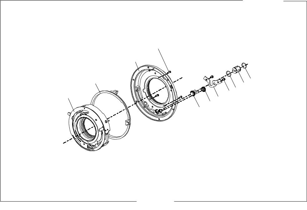
Front lens element / Front lens |
Tool No. |
|
• |
Unscrew engraved ring |
102165-0000-901 |
|
(snap ring is snapped in from the rear) |
|
• |
Unscrew front lens element |
102212-8105-901 |
•Unscrew lens holding ring
•Remove front lens
•Assembly is carried out in the reverse sequence analogously.
Rear lens element / Rear lens |
Tool No. |
|
• |
Unscrew rear lens element |
|
• |
Unscrew lens holding ring |
102212-8106-901 |
•Remove rear lens
•Assembly is carried out in the reverse sequence analogously.
Revision 0 |
July 1999 |

Carl Zeiss |
Repair Instruction 01:3:05 |
|
|
General
Removal of shutter unit
•Remove lens elements.
•Release shutter.
•Unscrew 4 screws of holding disk (from the front).
•Remove holding disk.
•Remove setting ring (mind the ball and spring of the notch).
•Remove diaphragm clutch ring and notched ring.
•Unscrew stop down handle.
•Remove spring and stop down ring.
•Unscrew 3 screws (01:3:05/1-1) of depth of field ring and one for grounding of flash contact (01:3:05/1-2), and remove depth of field ring.
•Unscrew one countersunk screw (01:3:05/1-3), one cylinder head screw (01:3:05/4) and remove case.
•Unscrew 3 screws from the back (at the shining surface).
•Remove shutter unit from the front.
•Assembly is carried out in the reverse sequence analogously (mind the ball in the setting ring).
1
2
3
1
1
4
Fig. 01:3:05/1
Revision 0 |
July 1999 |

Carl Zeiss |
Repair Instruction 01:3:06 |
|
|
General
Recommendation: Mark position of cocking shaft before disassembly of cocking ring (otherwise index will be disoriented by ±1 tooth).
1 2
|
1 Borehole |
|
2 Intermediate cocking gear |
|
3 Cocking shaft |
3 |
4 Mark |
5 Index
6 Spring for intermediate cocking gear
7 Spring suspension rivet
7 |
6 |
5 |
4 |
Fig. 01:3:06/1
• Test planartrueness and concentricity after fixing of case.
Removal of flash socket
•Snap out flash housing from the inside of depth of field ring with a wide screw driver.
•Unscrew nut with special tool (Tool No. 109950-0716-000, Former Tool No. 1450/8 385 614). For assembly, the nut has to be secured.
Removal of bayonet plate and focusing ring
•Release shutter.
•Snap out light tunnel.
•Unscrew 5 screws (mind the different length of 2 and 3).
•Remove focusing assembly by drawing it over the stop of the telescope shaft.
•Remove grip ring.
•Loosen 5 clamp screws around the focusing ring.
•Remove focusing ring.
Revision 0 |
July 1999 |

Carl Zeiss |
Repair Instruction 01:3:07 |
|
|
General
Exchange of telescope shaft:
• Clinch the screw (01:3:07/1-1) from the outside after assembly.
1
Fig. 01:3:07/1
•Screw in (for example after cleaning) of focusing mount is possible in any thread (For focal lengths 40, 50, 60, 80).
•Assembly is carried out in the reverse sequence analogously.
•Push the bayonet plate over the bearing and fix the screws under axial pressure. Mind the order.
1 |
2 |
3 |
4 |
|
6 5
Fig. 01:3:07/2
•Slip the focusing ring over the threaded ring and turn it clockwise until the stop.
•Fix the clamp screws and mind the order (see section ”Adjustment of the focusing ring“).
Revision 0 |
July 1999 |

Carl Zeiss |
Repair Instruction 01:3:08 |
|
|
General
•Screw focusing assembly onto the case (all 5 screws have to be secured). Mind the right position of the notch of the telescope shaft.
Fig. 01:3:08/1
• Insert the telescope shaft and push it over the stop.
Dismounting of Case
•See ”Disassembly of shutter unit”.
•See ”Removal of bayonet plate and focusing ring”.
•For assembly mind the position of the cam and the pinion. Turn the cam until the inner face of the pinion is in parallel to the outside and the face of the cam is at an angle of 40° towards the center line.
|
° |
0 |
|
4 |
|
//
Fig. 01:3:08/2
Adjustment of the focusing ring
•Remove the focusing grip ring.
•Set the focusing ring at ¥.
•Loosen 5 clamp screws.
•Turn away focusing ring by approx. 45° from the stop and secure by one clamp screw..
Revision 0 |
July 1999 |
Loading...