

Page 1

T2000 SERIES
PID TEMPERATURE
CONTROLLER
CARLO GAVAZZI
Automation Components
CGI Tempware Software Manual
Page 2

INDEX
KEY TO PROGRAM ICONS 2
OVERVIEW 3
INSTALLATION/CABLING
RS232 4
RS485 5
Termination resistors 6
Bias resistors 7
RS232/RS485 features 8
INSTRUMENT COMMS SETTINGS 9
CONFIGURING INSTRUMENT COMMS SETTINGS 10-11
INSTALLING SOFTWARE 12-13
GETTING STARTED 14
INSTRUMENT SCREENS 15
PC COM PORT SETTINGS 16-17
INSTRUMENT PARAMETER CONFIGURATION 18
SOFTWARE ALARMS 18
SETPOINT ADJUSTMENT 19
INSTRUMENT CLONING 20
SAVING SETTINGS TO FILE 21
SECURITY LOCKOUTS 22-23
LOGGING AND CHARTING 24-27
LOG ON CHANGE 28-29
EXPORTING LOG FILES 30
TROUBLE SHOOTING 31
GLOSSARY OF TERMS 32-33
Index
1
Page 3

Key to Program Icons
Change comms settings &
start monitoring
Toggle Modbus comms
de-bug window
Add new instrument
Add new instrument
Arrange instruments in grid
Make instruments larger
Make instruments smaller
Set security locks
Add new chart recorder
Close program
Create new file
Print chart recorder
Scroll chart up 100%
Scroll chart up 10%
Find chart zero
Scroll chart down 10%
Scroll chart down 100%
Expand verticle scaling range
Decrease verticle scaling range
Increase time/division
Decrease time/division
Open existing file
Export file in text format
Select units to record
Toggle grid density
Select background colour
Select primary grid colour
Select grid colour
Make chart bigger
Make chart smaller
Program Icons
2
Page 4

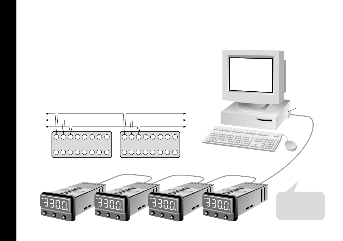
OVERVIEW
CGI T empware is a graphic WINDOWSTMbased software
package designed for PC supervision of Model T20321 /
T20161 and Model T20162 controllers. It offers the
capability of remote adjustment, instrument configuration,
cloning, saving and retrieving instrument settings to files
together with logging and charting in real time.
Communication uses the MODBUS
®
protocol via either a
fully isolated RS232 or RS485 link depending on the number
of instruments and the transmission distances involved in the
application.
PC Requirements
To gain the full benefit of CGI Tempware software, it is
recommend that the PC is fitted with a Pentium processor
and is running WINDOWS 95 or Windows NT programs. A
minimum of 16 Mb RAM is recommended to run the
program, together with enough free hard disc space to
meet logging requirements.
This manual assumes that a mouse or other pointing device
will be employed, but alternatively or in an emergency the
standard WINDOWS key convention can be used to
operate or close the program.
Because the controllers are “stand alone” they do not
need PC supervision for their normal function, and will
continue to control the process unaffected by failure of
any part of the communications loop.
Overview
3
Page 5

1 2 3 4 5 6 7 8
9 10 11 12 13 14 15 16
3300/9300
rear terminal
1
5
69
PC Com 1
DB-9 Pin
Tx
Rx
Gnd
COM port
Installation/Cabling
Installation/Cabling
4
RS-232 Is the standard most widely used for interfacing
peripherals to PC's and is designed for serial
communications with single instrument up to a distances
of 15 metres, in a low electrical noise environment.
Connection is via a screened two core cable where the
voltage signal on each line is referenced to the screen
which is grounded. Most PC's have one or two RS-232
compatible ports fitted as standard.
RS232 Connections
Port
Page 6
Installation/Cabling
Installation/Cabling
5
Tx Rx (+)
1 2 3 4 5 6 7 8
9 10 11 12 13 14 15 16
To
additional
units
1 2 3 4 5 6 7 8
9 10 11 12 13 14 15 16
3300/9300
unit 2
Tx Rx (-)
3300/9300
unit 1
Gnd
Tx Rx (+)
Tx Rx (-)
Gnd
Daisy chained connections
Connections if PC 485 card used
To RS 485 Interface
Either plug in board or
separate converter
Note:
Where separate RS 485
interface is used, refer to
manufacturers instructions for
connection details
To
RS 485
interface
COM port
RS485 Connections
RS-485 Is a half duplex serial communications link and is the
standard most commonly used for industrial applications due
to it's high noise immunity and multi-drop capability. It
enables a PC to communicate with up to 128 instruments
over distances up to 1200 metres, and requires the addition
of an RS-485 interface card, or a separate RS-232/485
converter.
Unit 2 Unit 1
Page 7

Installation/Cabling
Installation/Cabling
6
Termination resistors
–
120Ω
Tx
Rx
+
+
–
+
–
+
–
Tx
Rx
+
–
+
–
Tx
Rx
+
–
+
–
Tx
Rx
120Ω
Instrument 1 Instrument 2 Instrument ‘N’
Each RS485 interface has specific connection and
termination biasing requirements which will be detailed in
their installation instructions. The general principles are as
follows.
Terminations Because each wire is a transmission line, it
must be properly terminated to prevent reflections. Where
multiple instruments are daisy-chained together, a 120 ohm
terminating resistor should be fitted at the connection to
the PC and to the last instrument in the chain.
Page 8

Installation/Cabling
Installation/Cabling
7
Bias resistors
–
Tx
Rx
+
+
–
+
–
+
–
Tx
Rx
+
–
+
–
Tx
Rx
+
–
+
–
Tx
Rx
Instrument 1 Instrument 2 Instrument ‘N’
+5V
620Ω
-5V
620Ω
Bias resistors When transmission lines are not transmitting,
they remain in an indeterminate state which can allow
receivers to receive invalid data bits due to electrical noise
on the cable. To prevent this, the the lines should be forced
into a known state by fitting two 620 ohm bias resistors to
one point (node).
If an RS-485 interface card is being fitted to the PC,
separate bias resistors may not be needed because they
may already be fitted to the card. Check the manufacturers
specification.
Page 9
Installation/Cabling
Installation/Cabling
8
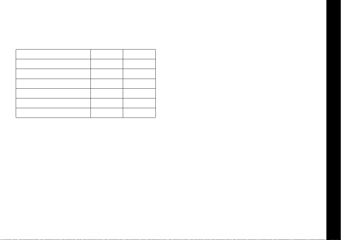
For a continually updated list of recommended RS-485
interface cards, contact Carlo Gavazzi.
Feature
Type of transmission lines Unbalanced
132
321
15M
19.2Kb/sec 19.2Kb/sec
+/- 25V + 12 to - 7V
1200M
Differential
Maximum number of drivers
Maximum number of receivers
Maximum cable length
Maximum data rate
Maximum CMV
RS232 RS485
Table lists the features of both RS-232 and RS-485
standards.
Cable To ensure data integrity over long transmission
distances, it is recommended that good quality RS-485 cable
is used.
Page 10

Instrument Comms Settings
Instrument Comms Settings
9
Immediately after power-up, both instrument, and PC comms
settings need to be made compatible before communication
between them is possible. Instrument defaults are shown
below together with the available options.
ADDR (Address) This is a unique
identification number that must be
allocated to each instrument
connected to the network.
Default =0. Options;
1 to 247
BAUD (Baud rate) The setting determines
the serial communication data
transmission rate in bits/sec, and must
match the PC settings
Default =
9600
.
Options;
1200;2400;4800;9600 and 19200
DATA (Data) Sets the transmission format, and
must match the PC settings.
Data Format Table
Settings Start bits
1
1
1
Data bits
8
8
8
Parity
n (none)
e (even)
o (odd)
Stop bits
1
1
1
Default
Option 1
Option 2
DBUG (Debug). Commissioning and
troubleshooting aid. Display shows
when the instrument is transmitting or
receiving data by rapidly flashing the
three horizontal segments of the first
and last digit of the display.
First digit = Tx; last digit = Rx
Default = Off. Options
off; on
Only use dbuG during commissioning or trouble-shooting
because it shares display segments and therefore
corrupts the normal display.
!
Page 11
Instrument Comms Address
Configuring Instrument Comms Settings
10
This should also be done immediately after power-up, and
is only possible from the instrument front panel.
On power-up the controller will display the self test
sequence followed by Alternating INPT and
nonE
INPT
CAL 3300
INPT
CAL 3300
INPT
CAL 3300
NONE
CAL 3300
NONE
CAL 3300
NONE
CAL 3300
INPT
CAL 3300
NONE
CAL 3300
Note: During the following procedure the display will revert
to alternating INPT and
nonE
after 60 seconds of
keying inactivity, but will retain any settings already
completed. Should this occur, or in the event of becoming
"lost" in the program, please start again from the alternating
INPT and
nonE
display
To select Level C (communications settings)
Press ▼ once display alternates LEVL and
5
Press and hold ✱ and press ▼ five times to reach level C
display alternates LEVL and
C
!
Note: Level C is only visible when the comms interface
board is fitted to the unit
To set up Instrument comms address
Press ▲ once display alternates ADDR and
0
Press and hold ✱ and press ▲ to index to chosen address
number
(1 to 247)
Note: In the absence of any conflicting information the
following comms settings should be left as the default
values. (see details on page 6).
To read or adjust comms settings
Baud rate
Press ▲ once display alternates BAUD and
9600
(Default setting)
Press and hold ✱ and use ▲ or ▼ keys to select preferred
value
Data format
Press ▲ once display alternates DATA and
18n1
(Default setting)
Press and hold ✱ and use ▲ or ▼ keys to select preferred
setting (see table page 6)
Debug setting
Press ▲ once display alternates DBUG and
oFF
(Default setting)
Press and hold ✱ and use ▲ key to select
on
Page 12

Instrument Comms Settings
Configuring Instrument Comms Settings
11
To enter settings into memory
Press and hold ▲ and ▼ for 3 seconds display alternates
INPT and
nonE
To check settings; repeat the above procedure
The unit is now ready to be configured from the PC.
Note: Where more than one instrument is connected to the
system, it is useful at this point to list them by location, title
and comms address. The list can then be used as a reference
to ensure that the the instruments are given the same identity
when configuring the comms link from the PC.
Page 13

Installing Comms Software
Installing CGI Tempware Software
12
1. From the Windows screen, click the Start button and
point to Settings.
2. Click the Control Panel icon then double click on the
Add/Remove Programs icon.
3. Click on the Install button and follow the screen
prompts.
When installation is complete, CGI Tempware should appear
in the Windows program menu.
To Uninstall CGI Tempware, repeat the above procedure.
To create a shortcut and put the CGI Tempware icon on
your desktop
Right click anywhere on the desktop.
Point to New then Click Shortcut
Type in Command line panel using syntax
exactly as shown:
"c:\Program Files\Carlo Gavazzi\
CGI Tempware\CGI Tempware.exe"
Click Next
In Select name for shortcut panel the
text will appear; CGI Tempware.exe
Click Finish, and this will place the title and
the CGI Tempware icon on the desktop.
Alternatively;
Overtype your preferred title in the Command line
panel then
Click Finish.
Check that the CGI Tempware logo appears
correctly titled.
An alternative method of defining the file path in the Create
shortcut window is to use the Browse function to find
CGI Tempware.exe
Click Browse
Double Click Program Files folder.
Double click CGI Tempware folder
Double click CGI Tempware.exe logo, then
Click Next, then
Click Finish, and check the CGI Tempware
icon and title.
Page 14

Installing Comms Software
Installing Comms Software (continued)
13
To delete a shortcut,
Click on the desktop icon then press the delete key
Page 15

Getting Started
Getting Started
14
Start the program running from either;
a. Windows Start menu
b. Shortcut icon (if created during
CGI T empware installation)
This will open the CGI Tempware window. The
screen can be sized using standard Windows
controls.
Note; As CGI Tempware is a supervisory program it is not
designed to be minimised
!
ADDING INSTRUMENTS
Click the appropriate Add New Instrument icon to
call up the type and number of instruments that
are to be shown on the screen. Each click
produces a new instrument which can also be
deleted by using the Close button in the
instrument title bar immediately above the
instrument screen. Mixed instrument types can be
displayed on the same screen.
Click the Arrange Instruments in a grid icon and
use the screen prompt to arrange them in the
preferred layout.
Click the Make Instruments Larger icon or;
Click the Make Instruments Smaller icon to size
them as required.
See screen illustrations overleaf.
Page 16

CGI Tempware Instrument Screens
Getting Started
15
Page 17

will automatically configure the com port settings. Where an
RS485 PC card is being used, refer to the manufacturers
installation instructions.
To open communication with the instruments in preparation for
Instrument configuration.
Click Change comms settings and start
monitoring icon, then select the comms
port that the instruments are connected
to.(eg comm 1 or comm 2) then Select
Baud rate to match the instrument settings,
(eg 9600) then Select Data Frame to match
the instrument settings, (eg 18n1)
Click Open Comms button
Comms Settings (on PC)
PC Com Port Settings
16
When the instruments are positioned on the screen, they are
automatically numbered in sequence Inst.1, Inst.2 etc. Each
one can be individually named in it's own title bar, and must
be given the same unique comms address (1 to 247) given
manually to the instrument during the Instrument Set-Up
procedure.
(CHECK your list!)
.
Right click in the display window of Inst.1 to open
the Internal Parameters for Inst1 screen.
If not already in User Level;
Click User Level tab to open page, then;
Point to instrument/name and if required,
change inst1 by typing in a preferred
instrument title.
Check Modbus address and if necessary
correct it to the given comms address
(1 to 247) by using the spin buttons or
by swipe and type.
(CHECK your list!)
Click on Update button and then Yes button
in Confirm / Update Instruments with
new parameters panel.
Instrument 1 should now have the correct comms
settings. The above procedure
must
be
repeated for all instruments on the
screen before starting Instrument
Parameter Configuration.
Note; If using an RS232 or RS485 converter plugged into
comm port 1 or comm port 2, the CGI Tempware software
Page 18

Comms Settings (on PC)
17
PC Com Port Settings (continued)
Wait!! For update to be fully completed by
observing the Uploading bar turning
from red to green in the CGI Tempware
Instrument screen.
This may take several seconds.
Check Virtual instrument display readings
against real instrument readings.
If the check is satisfactory, proceed with
Instrument Parameter Configuration
Page 19

Parameter Configuration
Instrument Parameter Configuration
18
The instrument(s) will not be operational until configured
with the following basic settings.
* Sensor type
* Units of measurement
* Allocation of output devices to the main output SP1 and
second output SP2
To configure the basic settings to Instrument 1
Right Click in the display window of Inst.1 (or new
given name) to open the Internal
Parameter screen
Click Level 2 tab to open page, then
Click Input sensor box, and select required
sensor from the drop down menu (eg
K
)
Click Process unit box, and select required
unit from the drop down menu (eg
o
C)
Click Level 3 tab to open page, then
Click SP1 output device box, and select
choice of output device from drop
down menu (eg
rLy
)
Note: That SP2 output device box registers the
alternative output device (eg
SSd
) and if
OK, Click the Yes button to confirm
selection.
Click User Level tab to open page, and enter
a setpoint value in Set Point 1/SP1 Value
box using spin buttons or swipe and
type.
Check The Enable Display Mimics box if you
want the virtual instrument to mimic all
actual instrument displays as well as
reading setpoint and process values.
NB This may slow down communications
and should only be used if it serves a
useful purpose.
SOFTWARE ALARMS
This feature provides a screen alarm indication if the
measured value falls below the low alarm and/or rises above
the high alarm settings.
The alarm appears as a red band across the lower fascia of
the instrument.
Page 20

Parameter Configuration
19
Instrument Parameter Configuration (continued)
To set Software Alarms (in User Level)
Adjust Spin buttons in Low Alarm/ High Alarm
boxes to set the required high/low level
Check The Enabled boxes.
TO ENTER THE ABOVE INSTRUMENT PARAMETER SETTINGS
Click on Update button and then Yes button
in Confirm/Update Instruments with new
parameter panel.
Wait For update to be fully completed as
indicated by the Uploading bar turning
from red to green after it temporarily
appears in the CGI Tempware Instrument
screen.
This may take several seconds.
After a few seconds more the Heat-On
LED in the top left hand corner of the
Inst.1 screen will light indicating that the
power is applied to the output.
Instrument 1 will control with factory
PID settings and pre-set proportional
cycle times. For optimum performance
the instrument may require Tuning to
match the characteristics of the
application. For full instruction in setting
the controller functions, please consult
the main manual.Autotune routines can
be found on page 7.
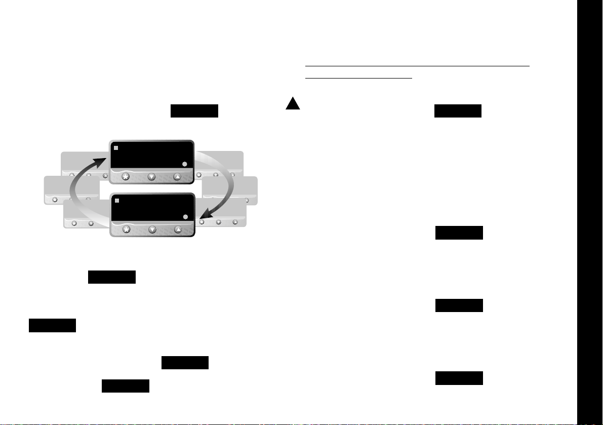
SETPOINT ADJUSTMENT
During normal use, instrument setpoints can be adjusted
from the CGI Tempware instrument screen, by using the
three buttons shown on the virtual instrument lower fascia.
✱ button highlighted with red circle in program
Click The ✱ button, and while the red circle
shows around it, click either the ▲ or
▼ button to increase or decrease the
setpoint value. This setting will be
implemented when the red circle
disappears after a few seconds.
Note: When more than one instrument is being configured,
the outputs of the other instruments can be temporarily
turned off using the
ParK
option of the TUNE function in
level 1.
Page 21

Instrument Cloning
Instrument Cloning
20
When a satisfactory instrument configuration has been
achieved, either from the initial configuration with the basic
parameter settings, following Autotune or other further
adjustments, these settings can be cloned to other
instruments on the network or saved in a file for later use.
Suites of settings of all the instruments in an application can
similarly be saved to a file making it possible to re-configure
all of the instruments on a machine or process in a matter of
seconds, to optimise them to different task.
Cloning Settings to another instrument on the bus.
Right Click in the display window of the instrument
that settings are to be cloned from.
Click the clone button in any of the pages of
the Internal Parameters for instrument
(n) screen to call up the Clone data
page. The Instruments on line panel will
list all of the instruments on line by it's
Modbus address and either the default
instrument number or name/location
given during Instrument Comms Setting
procedure.
To transfer an instrument or group of
instruments to the Instruments to Clone
panel;
Click anywhere on instrument title, to
highlight, or
Click/hold a group of instrument titles, then
Click the button to transfer the highlighted
instruments to the Instruments to clone
panel, then
Click the OK button to clone them with the
settings from the original instrument.
Page 22

Saving/Retrieving Instrument/Application Settings
Saving Settings to File
21
Saving the settings of a single instrument
Click Save in the menu bar of the Internal
Parameters for Inst.n screen
Type Your filename in the File name box
Click the Save box
This will save the instrument settings to an instrument file
with the extension .ins
Opening an existing instrument file
Click Load in the menu bar of the Internal
Parameters for Inst.n screen
Click the Yes button in the Confirm panel to
Load inst.n from file?
This will load instrument n settings to the new instrument.
Saving an Application File
In the CGI T empware Instruments screen
Click File in the menu bar, then Save
Application from the menu.
Type Your new filename in the File name box.
Click Save
This will save the settings of all the instruments on the
screen to an application file with the extension .app. Check
that the file is correctly named Yourtitle.app.
Opening an Existing Application File
Click File in the menu bar, then Open
Application from menu
Click File name to select application from the
list then click Open
This will automatically configure the instruments to the
settings saved in the selected file
Starting a New Application File
Click File in the menu bar and select New
Application from menu
Click Yes to confirm Start a new application
Note: When instrument settings are loaded from an
application file, remember to re-start comms
Page 23

Security Lockouts
Security Lockouts
22
When the instrument parameters have been established you may wish to password protect the settings against accidental or
unauthorised adjustment. It is possible to make individual protection for each instrument function at each level, and for each
instrument on the network
Please study the lock hierarchy diagram below before implementing your security strategy.
When correcting errors, start again from supervisor level, lock none, and clear the locked settings in the correct hierarchical
sequence
Supervisor
All of the controller functions are available to the supervisor
who can deny adjustment of any number of them to lower
levels in the hierarchy. These settings will be protected by
the supervisor’s password.
Operator
The operator can adjust all controller functions not locked
by the supervisor, and can in turn lock any of these to deny
adjustment to a user, and then protect them with the
operator’s password.
User
Any remaining functions are available for adjustment by the
end user. These functions can be locked and unlocked
without the use of a password.
All Controller Functions
Supervisor
Controller Functions Available to Operator
Operator
Controller Functions Available
for User Adjustment
Lock Hierarchy
!
Page 24

parameters you want to lock, or the All
box or the None box.
Click OK then
Click the tab for the next level, and repeat the
procedure until all levels of Inst.1 have
been protected.
Repeat for all of the remaining
instruments on the network, then return
to CGI Tempware instrument screen.
Click double lock icon in the menu bar to
bring up the Password panel, then
Click the arrow in the User type box and
select Locked from the drop down
menu.
Type your password in the Password box and
click OK. The selected levels of the
selected instruments are now locked
and protected by your password which
can be changed at any time using the
Change feature.
NB: Once communication has been established and routine
function adjustments under PC control, it is highly
recommended that the instrument controls are manually
locked to prevent unauthorised local adjustment. When
locked, it will still be possible to make adjustments from
the PC.
If you forget your password, please contact Carlo Gavazzi.
Security Lockouts
23
Lock Hierarchy
Right click in the display window of Inst.1 to open
the Internal Parameters for
Click the tab for a level that contains any
settings that you wish to protect, and
Click the Lock button, and in the Lock User
Level Parameter window,
Check either the individual boxes of all the
To implement your security lockout
strategy, begin from the CGI Tempware
instrument screen, supervisor mode.
Page 25

Logging and Charting
24
The CGI Tempware software is capable of logging readings
from up to 128 instruments which it stores in data files. The
data can be exported into text files which will enable the
data to be displayed in c.s.v. format, as columns of readings
against dates and times, for each of the 128 instruments. In
addition, the readings of up to 12 of the instruments can be
presented graphically and in color, by the chart recorder
facility.
As in other sections of the manual, it is assumed that a
mouse or pointing device is being used. Where only a
keyboard is available, the standard
Windows
key
conventions can be used to operate the program.
GETTING STARTED
From the CGI Tempware instrument screen.
Click the add new chart recorder icon in the
menu bar, and in the Chart recorder
screen;
Click the create new file icon, and in the File
name box of the Select File to Create
panel;
Type your chosen file name, then Click the
Save button.
In the Select Units to Chart screen;
Click to highlight all of the units that are to be
logged from, in the Available
instruments list.
Logging and Charting
Page 26

Logging and Charting
25
using the Add to Custom Color feature.
Click the OK box in the color screen.
In the Sample Frequency panel,
Click the spin buttons to set the log reading
frequency.
Click the OK button to open the Chart
Recorder screen.
In the Chart Recorder screen, check that
the Active File panel shows the correct
file name, then make the following chart
recorder settings to suit your application,
starting with the Scaling panel;
Logging and Charting (continued)
Click the transfer button to list them in the
Instruments to record table. For each
instrument to be charted from, double
click in the Plot? column to change the
No to Yes.
Double click in each instrument color panel, and
from the standard Windows
TM
color
chart, select contrasting colors that will
effectively display all of the instruments
listed. Additional shades can be added
Page 27

Logging and Charting
26
Click the buttons in the deg C/F box to set up
a suitable temperature scale in the chart
Y axis.
Click the buttons in the time/div box to set
chart speed in the time interval per minor
division of the X axis.
Click the Start button to commence logging
and run the chart recorder with default
chart settings.
Note: Chart scale settings are determined by the settings
chosen for the first instrument (or instrument 1)
Traces can be vertically positioned on the chart by using
the chart scroll buttons.
Click the buttons to move the chart up or
down by 10%
Click the buttons to move the chart up or
down by 100%
Click the button to zero the chart
The appearance and colors of the chart can be changed
as follows;
Click select background color icon, and
chose another color from the color
chart.
Click the toggle grid intensity icon to add
minor divisions to the Y axis.
Click the select primary grid color icon to
change the color of the grid major
divisions.
Click the select grid color icon to change
the color of the grid minor divisions.
Note: Because the chart is re-drawn after each plot, a
setting of less than 5 minutes/div is recommended, to avoid
extravagant use of system resources while logging. Longer
settings can be used to review the full chart history in view
plot mode.
!
Page 28

Logging and Charting
27
Click the make chart bigger or make chart
smaller icons to adjust the size of the
chart on your screen.
Click in the chart recorder blue title band, and
drag to adjust the position of the chart
recorder on your screen. Repeat this for
the CGI Tempware instrument screen,
and trim both adjustments so that both
are visible.
If you prefer using full screens for both
chart and instruments, toggle between
screens using the instruments menu bar
option in the chart screen and the chart
option in the instruments screen.
Click the pause button to stop logging and
stop the chart recorder.
Click the Resume button to re-start logging
and charting.Note that a grey vertical
band appears on the right of the chart to
signify the break in readings.
Click the auto plot button to pause the chart
and allow the chart history to be viewed
using the horizontal scroll bar controls.
(normal logging continues meanwhile)
Click the view plot button to return to
automatic chart update state and normal
charting is resumed.
During charting, the current value is
displayed to the right of the chart, in the
trace color. When in view plot mode
Point and Click to any point on the trace. A
dashed vertical line will appear and cut
the trace at this point, and the value will
appear to the right of the chart in place
of the current value.
If used in auto plot mode the reading will
be set to current value at the next plot.
Page 29

Log on Change
28
LOG-ON-CHANGE (ONLY LOG/CHART OUT OF LIMITS
READINGS)
This feature reduces the size of log and chart files by
ignoring readings that are within adjustable specified limits.
To specify the limits;
Double click in the inst.1 Min column and enter the
value
below
which readings are to be
logged. Repeat in the
Max
column, and
enter the value above which readings
are to be logged.
Check the radio button record when out of
tolerance, and Click the OK button.
The chart will now only register
out of
limits
readings which will be separated
by grey vertical bands signifying periods
of
in limit
readings. It will still be
necessary to set the Sample Frequency
buttons.
Check the radio button record all readings to
return to normal logging/charting.
Factor and Offset adjustments
A factor adjustment can be made to enable readings of
differing orders of magnitude to be charted on the same
scale. For example, a X10 factor applied to ambient
temperature readings would enable them to be charted
alongside process temperatures of 200
o
/400oC -
400
o
/1470oF. Factor adjustments can be greater or less than
one.
Offset adjustments can be applied to any trace to adjust its
position with respect to the scale. For example, the readings
from a particular instrument may be known to be 4
o
low
due to poor siting of the sensor. An adjustment of +4 in the
Offset column will remove this error.
Sizing and positioning your chart
Click to make the chart smaller or larger.
If required, it is possible to super-impose
a small chart screen on top of or beside
the CGI Tempware screen so that both
are visible.
Other Logging and Charting Options
Page 30

Log on Change
29
Saving Charts
To stop recording
Click Either the close button or from the
menubar chose File then Exit. The file
will automatically be saved with the
name given earlier as Givenname.cht
Files can be recalled to view, or to add additional data using
the Append feature.
Click the Open existing file icon, and select
the name of the file to be opened from
the list in the file box.
Click Open button.
The chart recorder screen will open with
the chart settings returned to default. If
preferred, reset the chart to your
original settings, then;
Click Append button to add the new readings
to the chart. The new readings will be
separated by a vertical gray bar.
Multiple Charts
It is possible to open a number of charts simultaneously. The
menu will register the number of charts open under the
chart heading. These can be arranged on the screen, in or
out of view, and moved or sized as required.
Page 31

Exporting Log Files
30
Exporting Log Files as Text Files
Log files can be exported as "Comma Separated Variable"
(csv) text files, which appears as column of logged
instrument readings, set against its time, date and line
number.
In this form the data can be exported into other
applications such as spreadsheets or data bases for use in
the preparation of reports or other management
documents.
To export data to a text file, in the Chart Recorder screen,
Click the export file in text format icon, and
in the Export Text File screen, type your
file name in the File name box.
Click the Save button to save your file as a
Filename.txt file
To check that your file has been correctly saved, open
Windows Explorer
And from the C:\ directory click Program Files then Carlo
Gavazzi then CGI Tempware
From the list contained under the filepath
C:\Program Files\Carlo Gavazzi\CGI Tempware\
Double click Select Filename.txt
Depending on the size of the file, it will be opened in either
Notepad or WordPad
Printing Charts
Charts can be printed in full color, depending on the
specification of the printer.
From the Chart recorder screen use either the print icon or
the print chart command from Options in the menu bar. This
will open the Windows
TM
print screen. Click the properties
button to select landscape setting. If changes in appearance
are required, review the logging and charting section.
Page 32

Trouble Shooting
31
Trouble Shooting
Error Message Fault Suggested remedy
ASK Comms error Check that the comms
address setting of the
real
and the
virtual
instruments are the
same.
_ _ _ _ Comms inactive Make sure that comms is
open.
Click Change comms
settings and start
monitoring icon.
Page 33

Glossary of Terms
32
Glossary of Terms
The following definitions apply to terms as they are use in
this manual, and have been worded for ease of
understanding. They may differ in detail to definitions
found elsewhere.
Address The unique number given to each
instrument on the network that enables
the PC to transmit individual instructions,
and receive individual data from it.
Application In this manual it defines the application of
an instrument or group of instruments to
control temperatures or other variables
on a machine or process.
Application file The stored settings of all of the
instruments on a machine or process.
Baud Serial communication consists of a stream
of on/off signals called bits. Baud rate is a
measure of the speed of communications
in bits/second.
Bus The electrical connection linking together
the instruments and the PC.
Charting Placing logged readings on a graph
format to form a continuous trace of
readings where the vertical or Y axis
measures the magnitude of the reading
and the horizontal or X axis measures
elapsed time.
Cloning Copying settings or groups of settings
from one instrument to another.
Comms Abbreviation of serial communications.
Daisy chain The method of connecting instruments
together.
Data format Defines the structure of the message.
Functions The main features available in the
controller.
Icon Small picture on a PC screen that
describes a CGI Tempware function that
can be clicked on to open or close the
function.
Level The instruments' functions are grouped
on five levels of adjustments for ease of
use and protection.
Logging Datalogging; Recording readings against
time and or date, into a file.
Modbus Generic name given to the format
(protocol) that defines the structure of
the coherent groups of signals in serial
communications.
Multi drop When several instruments are connected
together on a network using RS 485
standard.
Options The choice of settings for the Functions.
Password protect The arrangement that enables the user
to lock the system settings against
unauthorised adjustment with the use of
a word or code.
Continued over the page
Page 34

Glossary of Terms
33
Glossary of Terms
Glossary of Terms (continued)
P.C. Personal computer, desktop or laptop.
Protocol See Modbus.
Radio button A PC "screen" switch shaped like a push
button that can be clicked
on and off
RS232/RS485 Sometimes EIA232/EIA485 defines the
two standards for serial communication.
More detail can be found under
Installation/Cabling.
Serial Link Another name for the wiring between
two communicating devices.
Virtual Instrument Image of the instrument on the PC
screen.
Page 35

CARLO GAVAZZI INC.
Automation Components
750 Hastings Lane, Buffalo Grove, IL 60089-6904
Phone 847.465.6100 Fax 847.465.7373
email: sales@carlogavazzi.com
CARLO GAVAZZI
Automation Components
Control It
Current Monitors • Panel Meters
Phase Monitors • Timers
Transducers • Voltage Monitors
Distributed I/O
Dupline
®
Field and Installation Bus
Over a Twisted Pair • Up to 6 Miles (10km)
Send It
Sense It
Capacitive Proximity
Inductive Proximity • Level Controls
Photoelectric
Electromechanical Relays • Integral DIN
Mounted SSRs • Motor Controllers
Solid State Relays
Switch It
A Global Force in Industrial Automation
T2000 Manual 33058/01/0200
 Loading...