

Carl Goldberg Products Yak 54 Assembly Instructions Manual
WARNING
A radio-controlled model is not a toy and is not intended for persons under 16 years old. Keep
this kit out of the reach of younger children, as it contains parts that could be dangerous. A radiocontrolled model is capable of causing serious bodily injury and property damage. It is the buyer's
responsibility to assemble this aircraft correctly and to properly install the motor, radio, and all other
equipment. Test and fly the finished model only in the presence and with the assistance of another
experienced R/C flyer. The model must always be operated and flown using great care and common
sense, as well as in accordance with the Safety Code of the Academy of Model Aeronautics (5151
Memorial Drive, Muncie, IN 47302, 1-800-435-9262). We suggest you join the AMA and become properly insured prior to flying this model. Also, consult with the AMA or your local hobby dealer to find an
experienced instructor in your area. Per the Federal Communications Commission, you are required
to use only those radio frequencies specified "for Model Aircraft."
LIMITED WARRANTY
Carl Goldberg Products, Ltd. has inspected and certified the components of this aircraft. The company urges the buyer to perform
his own inspection, prior to assembly, and to immediately request a replacement of any parts he believes to be defective for their
intended use. The company warrants replacement of any such components, provided the buyer requests such replacement within a period of 90 days from the date of purchase and provided the defective part is returned, if so requested by the company.
No other warranty, expressed or implied, is made by the company with respect to this kit. The buyer acknowledges and understands that it is his responsibility to carefully assemble the finished flying model airplane and to fly it safely. The buyer hereby
assumes full responsibility for the risk and all liability for personal or property damage or injury arising out of the buyer's use of the
components of this kit.
CARL GOLDBERG PRODUCTS, LTD.
P.O. Box 818 Oakwood GA 30566 Phone #678-450-0085 Fax # 770-532-2163 www.carlgoldbergproducts.com
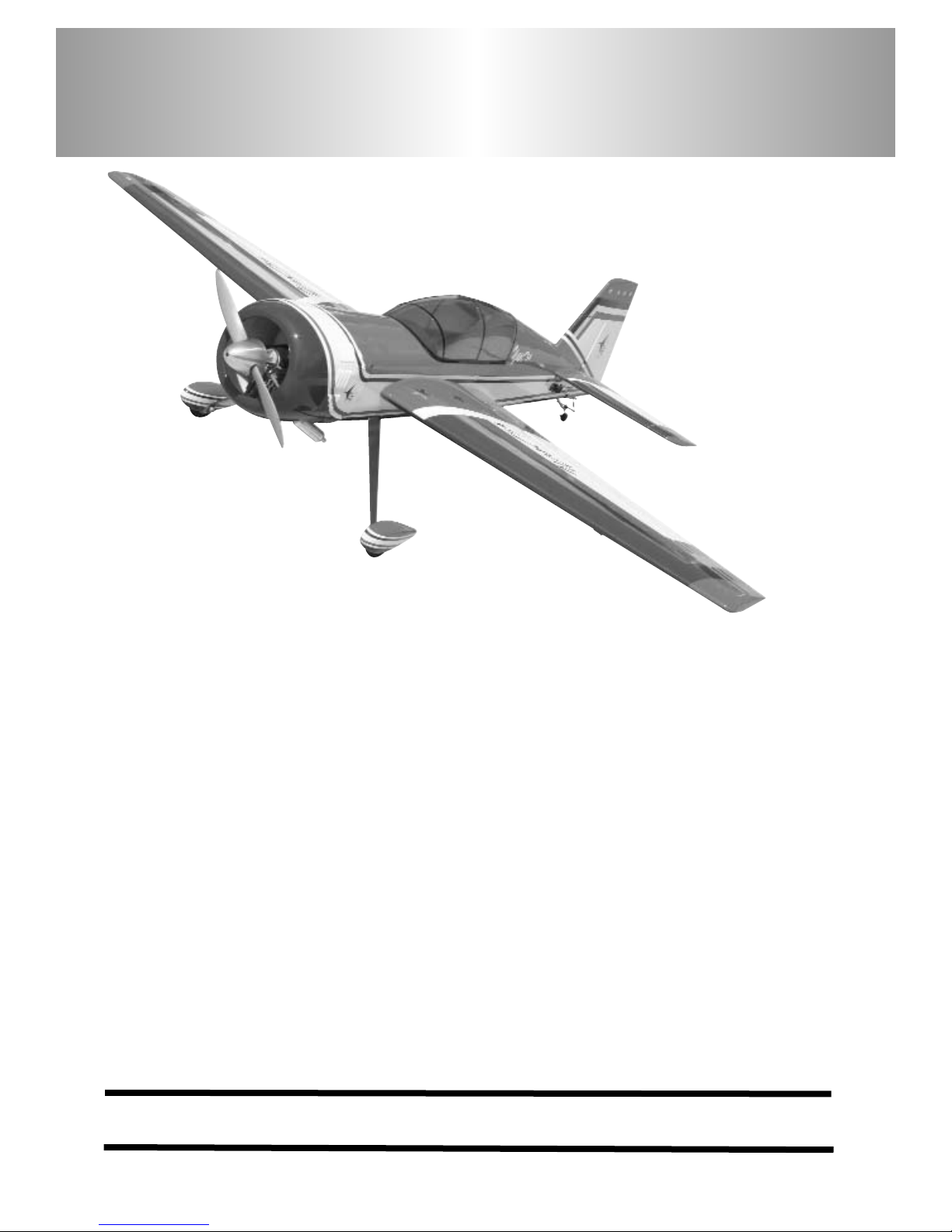
Aerobatic flying just doesn't get any better than this Yak54. The classic lines of a world class aerobatic plane
coupled with the radial cowl, add excitement to the maneuvers you love, knife edge, split S, lumcevac, torque
rolls, snaps, and ground-hugging inverted flight. What's more, we've engineered this ARF to get you into the
air with a minimum of fuss. So take a few minutes to carefully read the introductory material and then get to
work. You'll soon be out at the field with a classic aerobatic champion!
Y
Y
a
a
k
k
5
5
4
4
©copyright 2005 Carl Goldberg Products, Ltd.
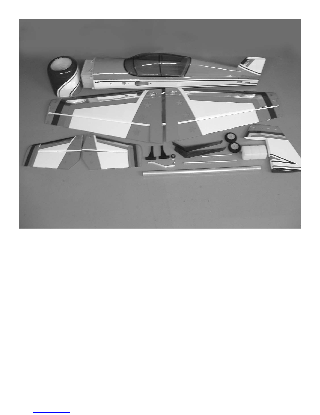
2
Cowl
Fuselage
Clear canopy
Left wing panel with aileron
Right wing panel with aileron
Stab half left
Stab half right
Elevator left
Elevator right
Motor mounts
Tail wheel bracket
Main gear
Wheels
Stab spars(aluminum tubes)
Wing tube (aluminum tube)
Fuel tank
Rudder

3
Before you begin assembling your Yak 54 ARF, take some
time to read through this entire instruction book. It is
designed to take you step-by-step through the process and
to give you added information on engine and radio selection
and set-up, balancing your aircraft, and flying your model.
The time you spend will speed the assembly process and
help you avoid problems.
PREPARING FOR ASSEMBLY
You will need a work area of approximately 24 x 70" which has been
covered to protect it from adhesive, as well as cuts and other
damage. Many people cover their work area with a sheet of
dry wall (sheet rock) and/or waxed paper t o prevent CA
Glue and Epoxy from ruining the work surface.
CONSTRUCTION TIPS
IMPORTANT: ALWAYS READ A FEW STEPS AHEAD.
This will alert you to coming instructions and will help you
plan accordingly.
Using the Parts Identification section, familiarize yourself
with the various items included in your kit box.
As you work, CHECK OFF EACH STEP in the box provided, so that you are sure you do not forget anything.
Do not hesitate to ask questions. Your local hobby dealer
and area flyers will most likely be happy to help, as they
want you to have a successful flying experience. You may
also receive technical assistance from Carl Goldberg
Products, Ltd. by telephone 1-678-450-0085.
ADHESIVES & GLUING TECHNIQUES
CA adhesives are specially formulated to firmly glue the plywood, hardwood, and balsa used in your model and to withstand the vibration and stresses of high performance flight.
However, there are times, such as when you are installing
the stabilizer and fin on the fuselage and want more setup time for careful alignment and positioning, then you
should use epoxy.. Occasionally, you also will want to use
thin CA, which "wicks" into the surrounding areas. Aliphatic
resin glue or similar water-based glues can also be used,
but they will add to the assembly time because they dry so
much more slowly than CA glue. Remember, when ever
using any CA, you must be careful to read instructions thoroughly, as you will have only seconds for positioning of
parts. Be sure to trial fit parts together before gluing. Also,
never use watery THIN type CA glue for gluing plywood and
hardwood parts. Thin CA's do not adequately bond these
areas.
CAUTION
Some people may experience an allergic reaction when
exposed to fumes from CA glue or epoxy. As with paints,
thinners, and solvents, it is always important to use glues
only where there is adequate ventilation to carry fumes
away. A fan is recommended. Also, special care must be
taken when using CA, as it will bond skin as well as other
surfaces. Before using any CA, carefully read all label precautions. When using CA, protective eye-wear and care in
keeping the glue away from the face is highly recommended. If CA does happen to get into the eye, hold lid open and
flush with water only. Seek immediate medical attention.
COVERING
The Yak 54 ARF is covered in a premium polyester film
chosen by many of the world's top flyers for its beauty,
toughness, and ease of application and repair. It is not
uncommon for ARF's to develop a few wrinkles in transit. If
this is true of your model, the situation is easily corrected.
Before you begin putting the pieces together, run over the
surface of each section with an iron (either specially
designed for airplane use or the more cumbersome household iron) or use a modeling heat gun. Apply the heat (set
at about 350° F), following along with a soft cloth and pressing down on the covering as you go around. This will more
firmly set the covering adhesive into the wood and keep
your aircraft covering tight and smooth in the future.
One of the great advantages of polyester film is that it can
be applied over itself without causing gas bubbles. This
allows you to repair your aircraft, as well as to customize it
in a number of ways. If, due to a flight mishap, you get a
hole or similar covering damage, simply trim away the
ragged edges and then apply a patch, following the directions that come with your covering , which is available at
your hobby dealer.
Important Information
Covering coming loose is not COVERED UNDER WARRANTY. Due to
temperature changes the plane may
develop some wrinkles in the covering that you will need to remove with
an iron. Be sure to seal the edges
down first so that you do not cause
the covering to shrink and leave
exposed areas of wood. Please
inspect the plane before beginning
to assemble to make sure you are
happy with it. After assembly has
begun you cannot return the kit. If
you find a problem before beginning
to assemble the plane you must
contact us, please do not return it to
the dealer.

4
ITEMS NEEDED TO COMPLETE THIS AIRCRAFT
1 RADIO GUIDANCE SYSTEM (4 CHANNEL
MINIMUM REQUIRED WITH 8 SERVOS)
2 12” AILERON SERVO EXTENSION WIRES
2 24” ELEVATOR SERVO EXTENSION WIRES
3 Y-HARNESS
1 ENGINE and PROP
1 CA ACCELERATOR
1 2 OZ. BOTTLE CA MEDIUM GLUE
1 1/2 OZ. BOTTLE CA THIN GLUE
1 20 MINUET EPOXY
1 1/4” FOAM RUBBER
OPTIONAL:
1 1/5 PILOT FIGURE
1 SPINNER 2-1/2” to 3-1/2”
NOTE: The Yak ARF covering matches Midnight
blue #885, Flame red #883, and White
,#870.
TOOLS AND SUPPLIES FOR ASSEMBLY.
MODELING OR UTILITY KNIFE
WORK SURFACE (24" X70")
ELECTRIC DRILL
1/16”, 3/32”,1/8", 3/16”, 5/32”, 1/4”, 5/64”
7/32” DRILL BITS
SMALL STANDARD & PHILLIPS SCREW-
DRIVERS
MASKING TAPE
NEEDLE NOSE PLIERS
MOTO TOOL
24” RULER
FLEXIBLE STRAIGHT-EDGE
30-60-90° x 6" TRIANGLE
SOFT PENCIL
A FEW STRAIGHT OR "T" PINS
ADJUSTABLE WRENCH
WIRE CUTTER (DYKES)
OPTIONAL HEAT GUN/COVERING IRON
ACID BRUSH
ELECTRICAL TAPE
PIECE OF MEDIUM SANDPAPER
5 FT. LENGTH OF STRING
Caution:
Before starting, carefully go over all high
stress areas with an epoxy or wood glue to
confirm all areas are well glued.
5
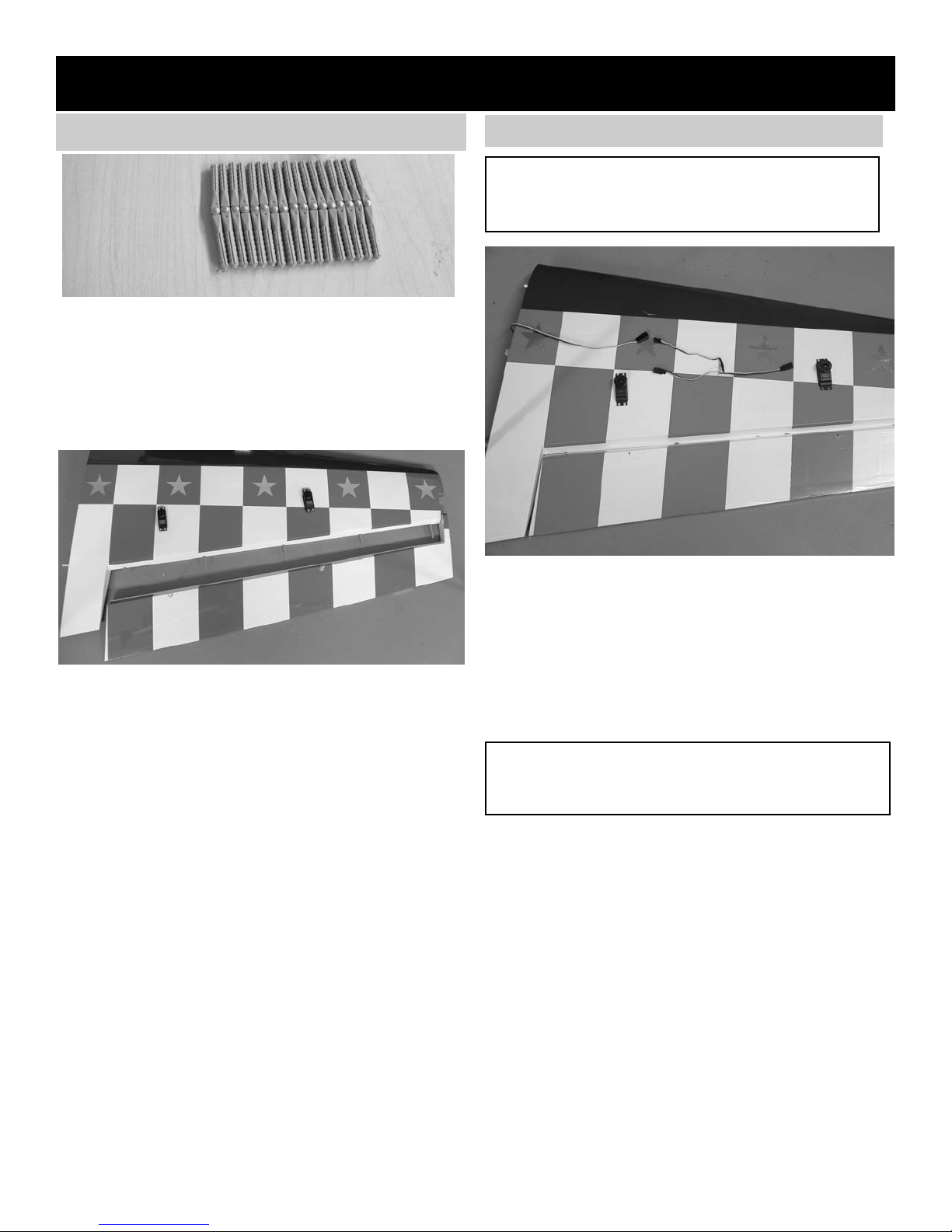
WING ASSEMBLY
AILERON INSTALLATION
2 Start with one wing panel. Locate the ailerons
and trial fit them on the wing. Make sure all the
hinges are aligned.
Now locate the other aileron and wing panel
and fit the aileron. When you are satisfied with
the fit, remove the ailerons and lay them
behind the wing in the correct position. The pin
style hinges work best if installed in both wing
and aileron at the same time. Apply a drop of
oil in the hinge.Use 30 minute epoxy to glue
them in.
Note: A syringe works great, if you have one
use a 1/8” dowel or piece of 3/32” wire to get
the epoxy into the holes. With glue in the
holes, push the hinges in wing up to the pin.
Apply glue in the holes on the aileron and slide
aileron into place. Work the aileron up and
down several times and the pin hinges will
rotate into position. Make sure you have a tight
fit between the wing trailing edge and aileron
leading edge.
Set aside to dry and install the other aileron.
AILERON SERVO INSTALLATION
Note: The following pictures may not exactly match
the hardware you are using. Always check the
radio manufacturer's instructions when installing
radio equipment.
1. Collect the following items:
(4)Servo mounting screw (supplied with
radio)
(1)Servo with rubber grommet (supplied with
radio)
(2) Servo extensions 12”
(2) y-connectors
IMPORTANT! To ensure that any connections locat-
ed inside the wing will not come loose, either when
the wires are pulled, or during flying, always tape
them securely together with electrical tape.
2. Making sure to use the correct servo for the
opening, attach the servo wire to the y-con-
nector and securely tape the connection.
Push the y-connector wire into the wing until it
comes out the other servo hole near the cen-
ter of the wing.
3.
Connect the other servo and and the 12”
extension to the end of the y-connector.
Install the servo with the output arm forward.
4.
Grasping the extension in the hole, SLOWLY
pull until the end of the extension comes out
of the hole at the center of the wing..
Tape the extension securely to the wing, so
that it will not slide back in while you are work-
ing.
1. Collect the following parts:
(1) Left wing
(1) Right wing
(1) Left aileron
(1) Right aileron
(10) pin hinges
6
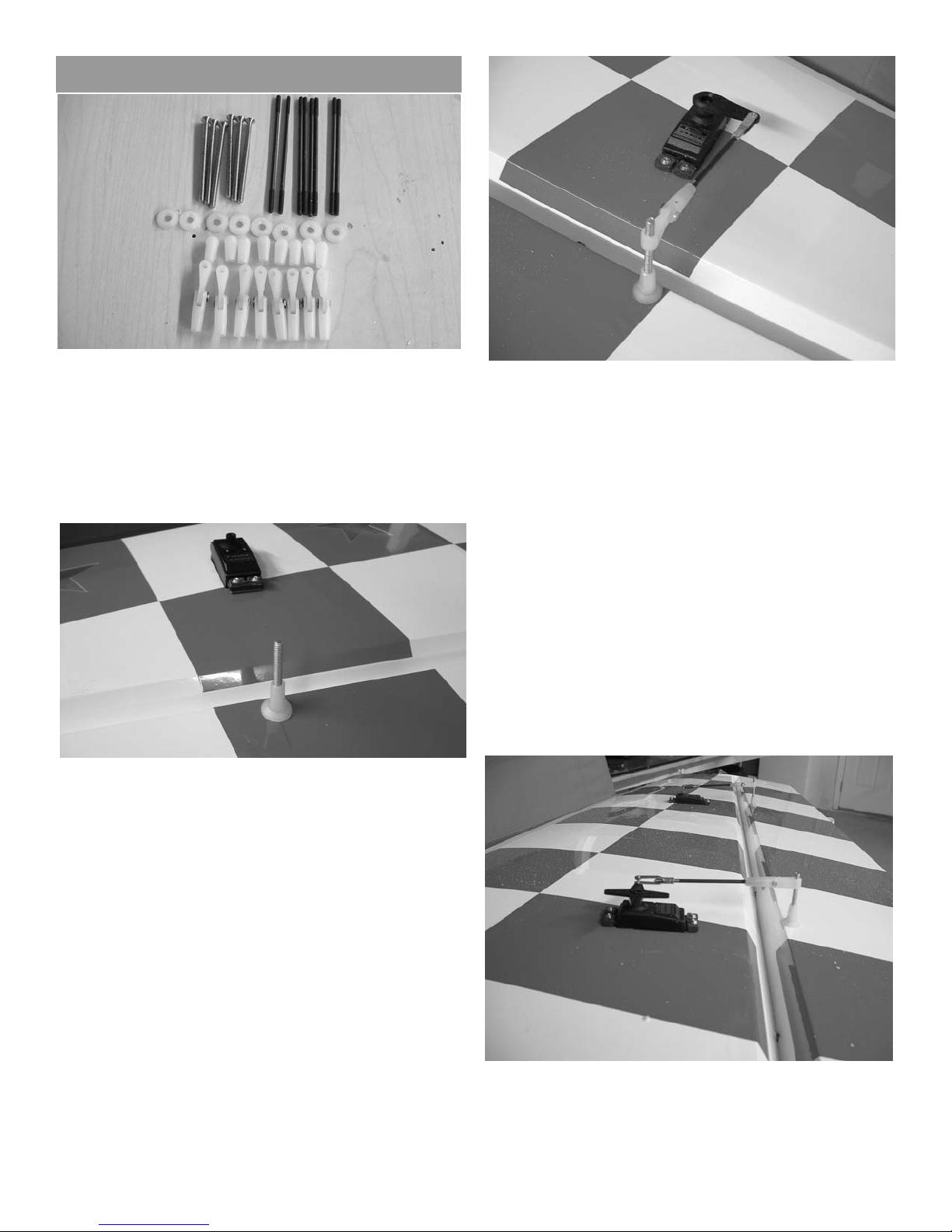
AILERON CONTROL HORN INSTALLATION
1. Collect the following items
(4) Nylon clevis assemblies
(4) nylon ball nuts
(4) 6-32 x 3” Bolt
(4) nylon washers
(4) 4-40 x 4” pushrods
(4) 4-40 clevis
(4) clevis keepers
2. With the aileron servo in place, make a mark
at a 90º degree angle to the trailing edge and
in line with the servo arm.
3.
Use the mark to locate the hard point installed
in the aileron( dowel with hole in middle).
4. Using a 9/64" drill bit, open the hole in the
aileron through to the top side.
HINT: Drill the hole from the bottom half way. Then
drill down to the hole from the top of the
aileron.
5. Insert the 6-32 x 3” screw from the top through
the aileron.
Place the nylon washer and the nylon ball nut
on the bolt and tighten.
Screw the adjustable clevis assemble on the
bolt.
6. Thread on to one end of a 4-40 x 4” pushrod
a nut and clevis.
Mount the pushrod onto the nylon clevis
assemble on the aileron.
With the servo centered, connect the pushrod
to the control horn.
With one servo connected and the radio on,
connect the other servo pushrod making sure
that there is no pressure on the other servo.
Install the clevis keepers.
Repeat the above steps for the other two
aileron servos.
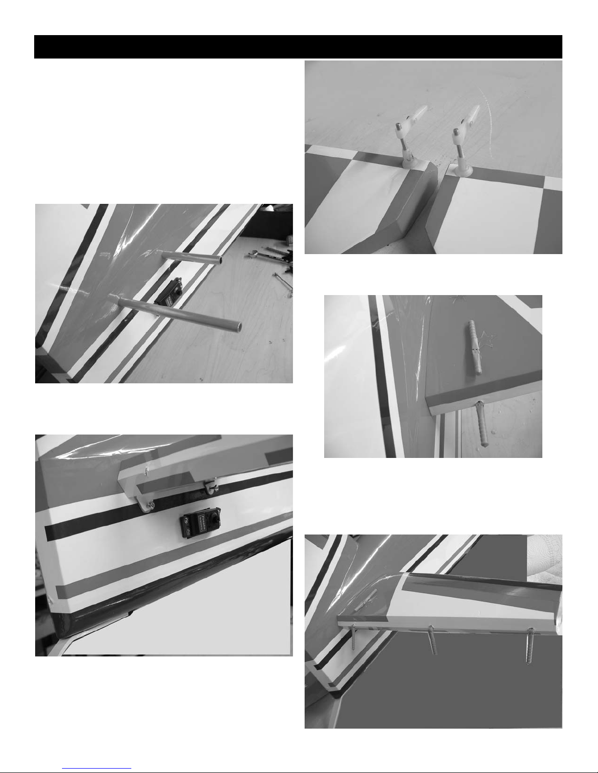
7
Collect the following items
(1) Stab
(1) Fuselage
(1) Stab halves
(6) pin style hinges
(4) 4-40 x 1/2” bolts
(2) aluminum stab tube
(2) 6-32 x 3” bolts (control horns)
(2) nylon ball washers
(2) nylon ball nuts
(2) nylon clevis assemblies
Tail Construction.
1. Install the two aluminum stab tubes in the fuse-
lage with the longer one in the rear.
2. Slide the stab half onto the tubes and tightly
against the fuselage side. Install the two 4-40
x 1/2” bolts into the mounting tabs on the bottom of fuselage. Blind nuts are pre-mounted in
the fuselage. Be sure to use lock-tite on the
bolts. Repeat for the other stab half.
3. Install the control horns on the elevators in the
same manner as you did the ailerons.
4. Because of the location of the stab tube, the
inboard elevator hinge will have to be cut off at
the end of the second serration, cut off 1/2”.
Make sure hinge will go into stab up the hinge
pin.
 Loading...