


Super
Chipmunk
Instructions
Another loop, roll and then a plunge earthward into a dive trailing billowing white clouds of smoke. Perilously close to the ground it pulls out and zooms a few hundred feet into a hammerhead stall. No, it isn’t Art Scholl performing at a summer airshow, its the C.G. version of his Super Chipmunk at a R/C fun-fly. We’ve dedicated our model of the Super Chipmunk to the memory of its designer and creator, Art Scholl. His breathtaking precision aerobatics demonstrated to millions the safety and grace of disciplined flying.
Our Super Chipmunk’s super-stable, low speed manners let you fly at a crawl and it simply won’t quit. Bring it in a little nose high, and you’ll still have solid control to a perfect touch-down. Turn it loose and this performer will put on a airshow with all the flash and flair of the original.
Additional Items Needed:
4-5 channel radio
CA glue and epoxy
.45 to .61 (.90 4-cycle) R/C engine
2-1/4” CGP snap-on spinner
Propellers, fuel tank and tubing to suit engine.
14 running feet of covering material
Paint
One 1-1/4” and two 3-1/4” Wheels
Foam rubber
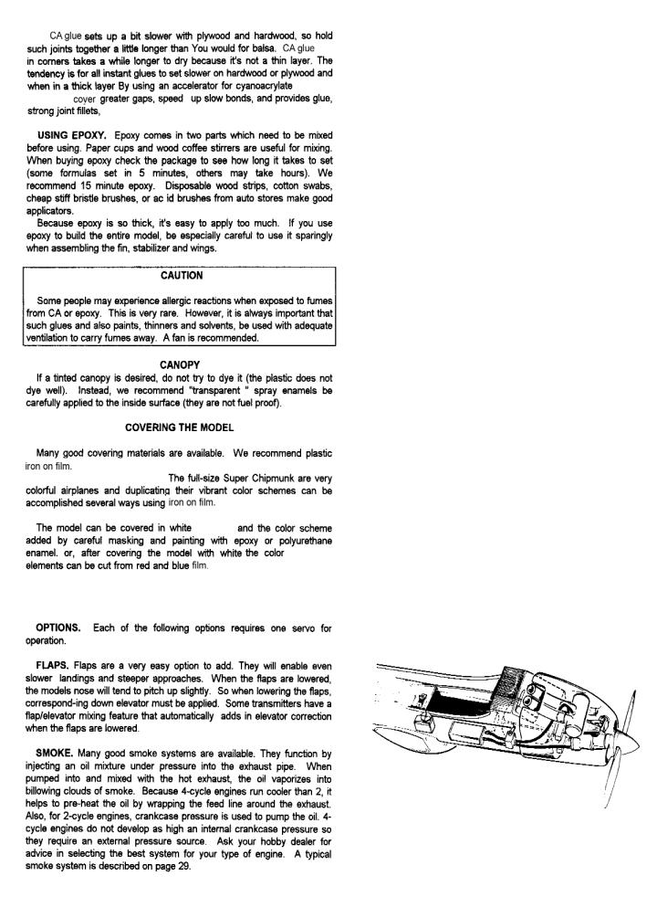
Optional Wing Flaps:
CG 3/32” Strip Aileron Set
CG True 1/16” pushrods
1/8” x 3” x 6” Aircraft Plywood
Tools & Supplies Needed
Miscellaneous rubber bands Wax paper
Modeling knife or single edge razor blade Sandpaper
Pins
Drill sizes:
1/16”, 5/64”, 3/32”, 1/8”, 5/32”, 3/16”, & 1/4” Flat building board
Pliers
Small Screwdrivers
Iron for applying covering Masking tape
CARL GOLDBERG PRODUCTS, LTD.
©Copyright 1988 Carl Goldberg Products Ltd.

2
3
4
5
ASSEMBLING TOOLS
Diecut beveling tools (from 1/8” ply)
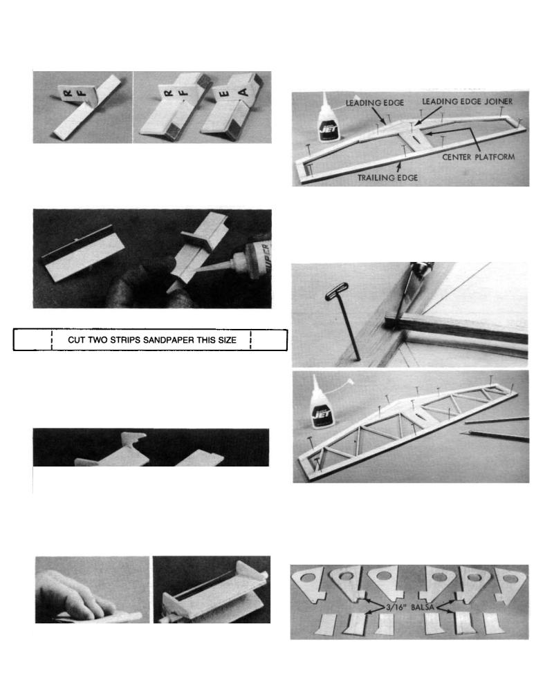
1. First, glue narrow strip to handle, keeping them
square, as shown above left. Then glue wide strip to handle and narrow strip, again keeping things square.
2. Cut two strips of 100-200 sandpaper to size shown above. Tack-cement sandpaper to tools as shown.
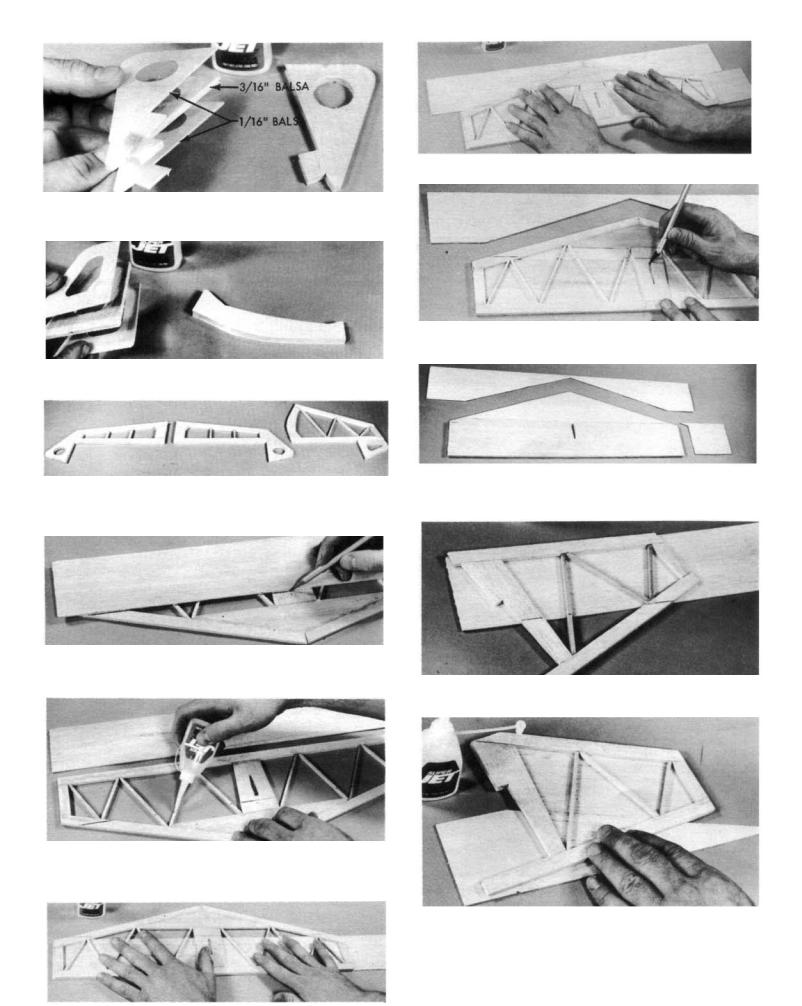
TAIL ASSEMBLY
The stabilizer and fin are sheeted with 1\16” balsa, and their interior frames are 3/16” thick balsa. The elevator and rudder are not sheeted, and their frames are 5/16” balsa. for clarity, the stabilizer and fin are built first and then the elevator and rudder.
1. Make stabilizer (stab) leading edge (LE.) from 3/16” x
1/2” balsa sticks. Cut balsa carefully to match with plan at center joint and exact length at tips.
Pin in position, and glue at center joint.
Using die-cut L.E. joiner, center platform, and 3/16”x1/2” balsa, glue outline together.
DIE-CUT SANDING TOOL
1. Glue one strip into handles notches keeping them square. Then glue remaining strip to other half of handles.
2. Cut one piece of 100-200 grit sandpaper to size of 2-1/4”x3”.
Center 1/4” dowel over grit side of sandpaper. Roll sandpaper around it as shown above left.
Slide dowel and sandpaper into tool and hold with rubber band as shown at right. Glue sandpaper to tool.
2. From 1/8” x3/16” strip balsa, cut all trusses to size over plan. Trim well-don’t force into place. Glue in place.
Let dry thoroughly.
3.Assemble fin in same manner as stab, using die-cut and
stick parts.
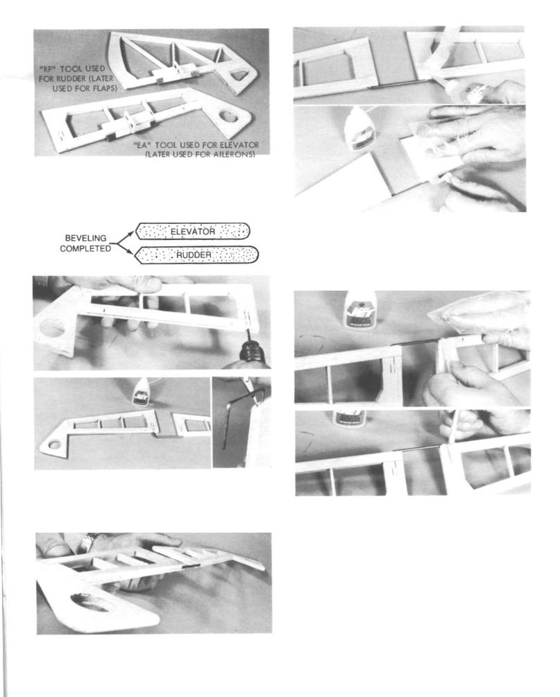
4. The die-cut balsa parts for elevator and rudder must be
6
Begin by gluing a 3/16” core between 1/16” top and bottom pieces. In this manner make two elevator tips and two inner ends as show
Laminate rudder pieces in same manner,.
Laminate center section.
5. Assemble elevator halves and rudder in same manner as
stab and fin, except use 5/16”x1/2” balsa for L.E. and 1/8” x 5/16” for trusses.
6a. Flush edge of 1/16”x3”x24” balsa sheet even with stab T.E. and allow a little extra at tip for trim off. Mark sheet
width on stab to show gluing limits.
Remove sheet and apply CA to T.E., tips and trusses. Turn stab over, position on balsa sheet and press down flat
on table.
Center second sheet under stab L.E. and glue in place.
Cut out center slot in stab platform for fin post.
Carefully trim balsa sheet to match stab outline.
Turn stab upside down and cover other side in same manner.
6b. Flush balsa sheet with fin L.E. and glue.
Use stab scrap to complete fin sheeting as shown.
Trim sheet to match fin outline.
7

7. Place fin and rudder over plan and mark hinge locations.
Mark hinge locations for stab and elevator.
Position elevator halves and joiner over plan, and carefully mark elevator L.E.’s for wire joiner location.
8. Using CG Center-line marker provided, mark center-
lines along edges of parts as shown above. Tilt marker so guide pegs touch the wood, then lightly pass the marker back
and forth. Point will scribe center line.
9. At locations marked in Step 7, make a slit wide enough for the JET Hinge to fit into.
IMPORTANT! Although you are installing the hinge now, the hinges are not permanently installed until after the model is covered.
12. Using no glue, TEMPORARILY attach elevator to
stab and fin to rudder with hinges in place. Hold parts together with tape.
First break corners with the sanding block. Then, follow low with stab sanding tool, rounding off all outside edges
except bottom of fin and rudder. Blend stab and elevator at tip.
Using a sanding block, flat sand stab, elevator, fin and rudder, smoothing out surfaces.
8
13. Remove tapes and separate elevator and rudder from stab and fin.
Tape T.E. of elevator and rudder to work surface, using appropriate beveling tool, sand L.E. to center-line. Turn parts over and repeat beveling for other side.
14. Using no glue, trial fit elevator halves together with
wire joiner. Carve a radius for better fit at wire bend. Elevator halves must lie flat on table and L.E.’s must be aligned. Punch a small pin hole through elevator at rear of joiner hole for glue squeeze-out. Glue joiner in place.
15. For strength, the elevator joiner areas should be rein forced with nylon fabric as follows.
Apply a dab of CA to the elevator and press one end
of nylon fabric into it (cover finger with a plastic bag or similar).
Apply a squiggle of glue to elevator and pull nylon fabric down into it. Rub nylon into the glue with your finger.
Continue gluing and apply nylon around elevator front and around to other side. Trim nylon Cut.
Repeat this procedure and apply nylon on other
joiner area.
This completes the tail assembly construction.
9

Wing Assembly
PROCEDURE: The wing panels are assembled bottom side up and then turned over for joining and finishing.
IMPORTANT! Although the wing is a symmetrical section, because of internal structure (landing gear and aileron bellcrank mounts), some ribs are not symmetrical(such as Ribs No. 2,4,7,&8). As an aid for proper rib orientation, the tip spar notches for some ribs have only been partially laser cut. IMPORTANT, wing assembly will begin with building a panel overt the “RIGHT WING” on the full-size plan, later on when it is turned over, this wing will of course become the left wing. “Right” or “Left” wing refers to the panel being assembled during that particular step OVER THE PLANS.
Since the wing is built in two halves, and steps 1 to 17 are repeated in the process, two check boxes are provided with each of these steps. One for the right wing and one for the left.
1. Position one main spar in place over RIGHT WING (or
LEFT WING) on plan. Align spar at center of wing on plan. Hold spar in exact position by crosspinning at circled location on plan. CAUTION: Do not build two RIGHT WINGS!
2a. Lay parts out as shown. Glue plywood rib doubler 3
to rib 3 (IMPORTANT! Position slot in ply doubler at top edge of rib 3).
DOUBLERS MUST FACE EACH OTHER IN WING.
2B. Lay parts out as shown. Glue plywood rib doubler 5 to rib 5.
Face ply doubler towards rib 4
location Notched end
No notch here
2c. Using no glue, place platform ribs 3,9, & 14 on spar at their
respective places over plan (position rib 3 so ply doubler faces towards rib 4)
Rest notched Trailing Edge (T.E.) on rib platforms (Important: the T.E. has no notch at one end-this unnotched end must be at wing center as shown).
Press T.E. on rib 3 then slip ribs 9 & 14 into their respective notches,. Pin T.E. to ribs and rib platforms to building board. Glue ribs to T.E. and spar (avoid gluing T.E. to rib platforms).
Face ply doubler 5 towards rib 4
With landing gear slots facing up, set ribs 4 & 5 in position (NOTE: rib 5 ply doubler must be facing rib 4).
Working one at a time, glue remaining ribs 2 to 8 & 10 to 15 to spar and T.E. (NOTE: slots in rib 2 must be towards upper rib edge, slots in ribs 7&8 must face up towards rear of wing as shown). Hold each rib straight up as it dries. IMPORTANT: for a warp free straight wing, make sure T.E. is kept straight and not bowed up or down, shim with balsa if required.
10
3. Position the Set-Back Gauge (SGB) touching the bot-
tom spar. Touch end of top spar to gauge, and set spar in rib slots.
True top spar to all ribs.
4. With slot facing out from wing, glue landing gear block to ribs 3,4,&5.
5a. Drill four 5/64” dia. holes(1/16” will do) at punchmark locations through aileron bellcrank mounting plates.
5b. Position aileron mounting plate in rib 7&8 slots, this part is designed to fit only one way. Glue plate in place.
6a. Pin wing at outside of ribs 2 & 15 and T.E. and remove pins from interior area of wing.
6b. Align T.E. sheeting with center end of T.E. and adjust sheet
so it is flush along T.E. Glue in place. If sheeting edge is not straight, let excess hang out over T.E. for trim off later.
6c. Gl ue 3/16”: Sq. x 36” balsa into forward rib notches. Cut to
fit around L.G. mount. Balsa should project out from rib 2 about the same distance as main spar.
7. An opening for the L.G. mount must be made in the L.E.
sheeting. Begin by aligning 5/65”x3”x36” L.E. sheeting with front edge of spar and flush with spar end.
Project and mark two lines straight back from the ends of the L.G. mount and on to the L.E. sheet.
Slide sheeting over to side of L.G. mount. Align sheet with
back of spar and measure and mark the front and rear L.g. block locations. Measure L.G. block locations from the back of the spar.
Cut the opening a little undersize at first and try in place. Enlarge opening as required for proper fit.
11
 Loading...