

CCAARRLL GGOOLLDDBBEERRGG PPRROODDUUCCTTSS LLTTDD..CCAARR
P.O. Box 818, Oakwood, GA 30566 • 678-450-0085 • Fax: 770-532-2163 • www.carlgoldbergproducts.com P.O.
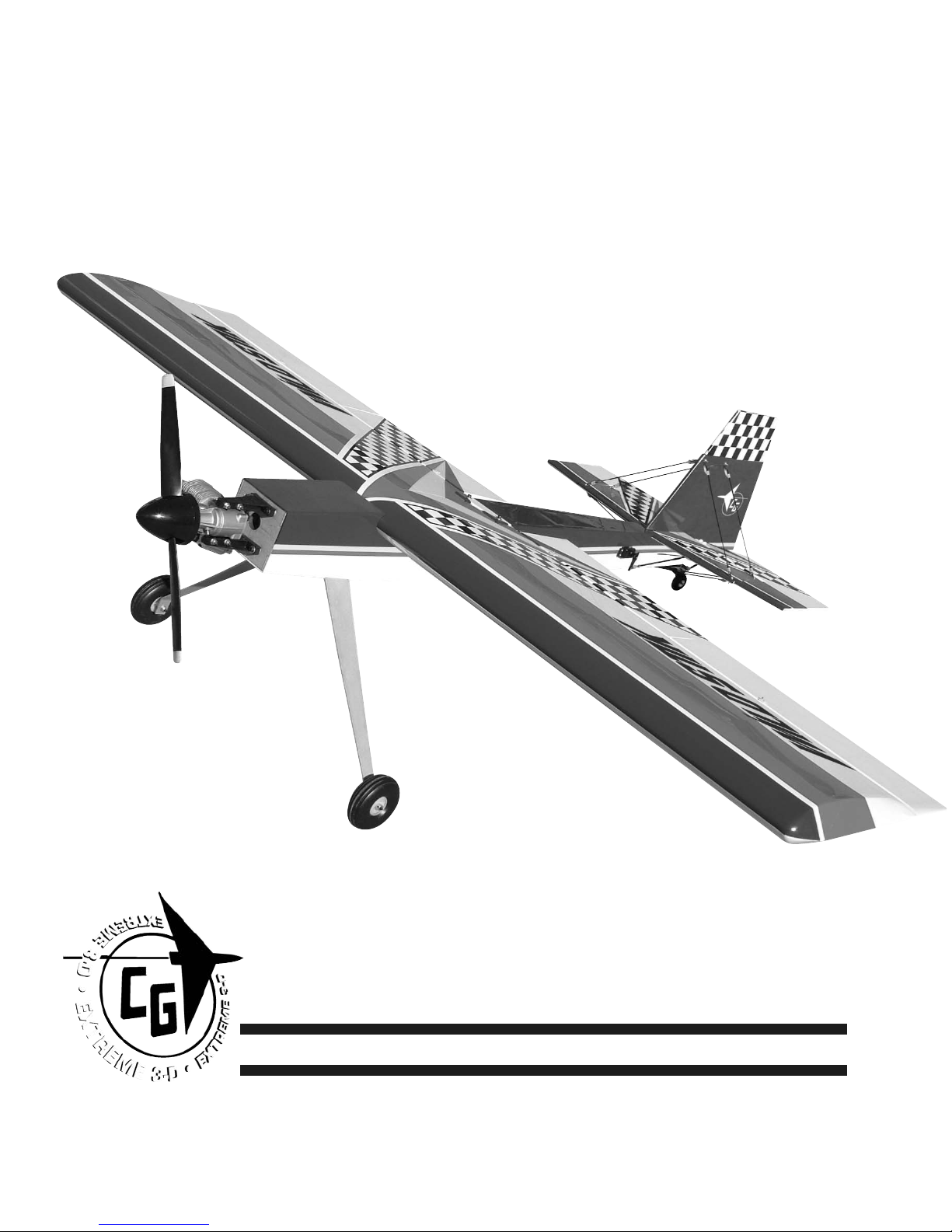
Wild Stick 120
Wild Stick 120
©copyright 2004 Carl Goldberg Products.

2
Wild Stick 120
WARNING! THIS IS NOT A TOY!
THIS IS NOT A BEGINNERS AIRPLANE
This R/C kit and the model you will build from it is not a toy! It is capable of
serious bodily harm and property damage. It is your responsibility, and yours
alone - to build this kit correctly, properly install all R/C components and
flying gear (engine, tank, radio, pushrods, etc. and to test the model and fly
it only with experienced, competent help, using common sense and in accordance with all safety standards as set forth in the Academy of Model
Aeronautics Safety Code. It is suggested that you join the AMA and become
properly insured before attempting to fly this model. If you are just starting
R/C modeling, consult your local hobby dealer or write to the Academy of
Model Aeronautics to find an experienced instructor in your area.
Write to: Academy of Model Aeronautics, 5151 Memorial Dr. Muncie, IN
47302
LIMITED WARRANTY
Carl Goldberg Products is proud of the care and attention that goes into
the manufacture of parts for its model kits. The company warrants that for
a period of 90 days, it will replace, at the buyers request, any part or material shown to the company's satisfaction to have been defective in workmanship or material at the time of purchase.
No other warranty of any kind, expressed or implied, is made with respect to
the merchandise sold by the company. The buyer acknowledges and understands that he is purchasing only a component kit from which the buyer will
himself construct a finished flying model airplane. The company is neither
the manufacturer of such a flying model airplane, nor a seller of it. The
buyer hereby assumes the risk and all liability for personal or property damage or injury arising out of the buyers use of the components or the finished
flying model airplane, whenever any such damage or injury shall occur.
Any action brought forth against the company, based on the breach of the
contract of sale to the buyer, or on any alleged warranty there under, must
be brought within one year of the date of such sale, or there after be
barred. This one-year limitation is imposed by agreement of the parties as permitted by the laws of the state of Georgia.
Important Information
Covering coming loose is not COVERED UNDER WARRANTY. Due to temperature changes the plane may develop some wrinkles in the covering that you
will need to remove with an iron. Be sure to seal the edges down first so that
you do not cause the covering to shrink and leave exposed areas of wood.
Please inspect the plane before beginning to assemble to make sure you are
happy with it. After assembly has begun you cannot return the kit. If you find
a problem before beginning to assemble the plane you must contact us,
please do not return it to the dealer.

3
Wild Stick 120
Wild Stick
Wild Stick
Congratulations on your purchase of the Lanier Wild Stick 120. This is a very
unique aircraft, with great 3-D capabilities. Every effort has been made to
produce a lightweight, straight, easy to assemble aircraft. Because of its
oversize control surfaces which are double beveled to allow for extreme
throws, great care must be taken in the set-up and flying of this airplane.
Quality hardware components have been provided to allow for 3D set-up
while maintaining adequate mechanical advantage to eliminate flutter. It is
you responsibility as an advanced pilot to fly the aircraft in an intelligent
manner. THROTTLE MANAGEMENT IS A MUST!!!!!!!! We at Lanier have put the
Wild Stick 120 through a very rigorous flight-testing schedule and have
stressed the airframe beyond all practical parameters without a single failure. Lanier will NOT warrant the Wild Stick 120against flutter due to improper set-up or excessive speed maneuvers. having said that, we believe you will
find the Wild Stick 120 to be one of the most responsive, in-the-grove aircraft
on the market. The Wild Stick 120 excels at high-alpha maneuvers including
Harriers (both upright and inverted), high-alpha rolls, and high-alpha knife
edge. Torque rolls, waterfalls, knife edge loops and elevators are all within
the performance parameters of this unique aircraft. Just remember to use
common sense when flying this high performance machine.
4
Wild Stick 120
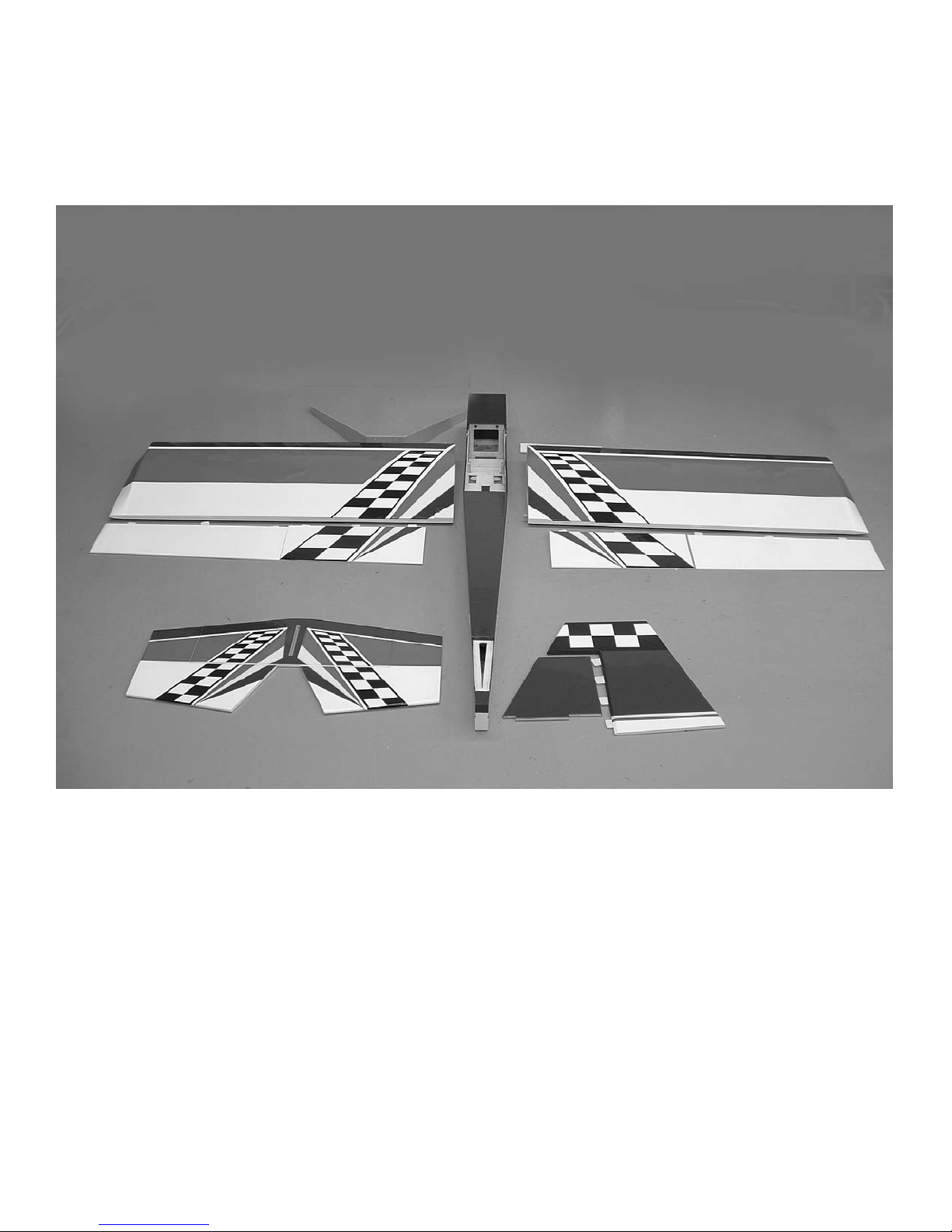
Parts Layout
Fuselage 1
wing panels 2
ailerons 2
Flaps 2
Stabilizer 1
Elevators 2
Fin 1
Rudder 1
landing Gear 1
Colors
Red True red #866
White #870
Black #874
Blue Deep Blue #873
yellow Bright Yellow #872

5
Wild Stick 120
Landing Gear 1
4mmx12mm bolts 4
4mm washers 6
4mm wheel collars 4
4mm axels 2
4mm lock nuts 2
3.5” wheels 2
Motor Mounts 2
4mmx20mm bolts 4
4mmx25mm bolts 4
4mm blind nuts 4
4mm flat washers 8
4mm lock nuts 4
Flying Wires
1.8mmx16mm bolts 6
1.8mm nuts 6
1.8mm washers 12
metal brackets 12
nylon swing in keepers 8
1.6mmx10” pushrod with clevis 4
1.6mmx7” pushrod with clevis 4
metal plate(bottom bracket) 1
silicone clevis keepers 8
2mmx10mm screws 2
Control horns 8
control horn plates 6
2mmx20mm screws 14
2mm nuts 2
Pushrods
3mmx10cm pushrods(aileron) 4
3mmx20cm pushrods(elevator) 2
3mm metal clevis 12
3mm jam nuts 12
Braided cable feet 6
Rigging couplers 2mm 4
cable swages 4
2mm clevises 5
2mm jam nuts 5
Silicone clevis keepers 17
2mmx50cm throttle pushrod 1
Pushrod connector(e-z connector)1
plastic tube 4mmx25cm 1
Hardware List
Wing bolts
4mmx40mm 2
4mm flat washers 2
Fuel tank with hardware 1
Tail wheel
Tail wheel bracket
metal rudder horn
spring wire axel
springs (2)
wheel collar
tiller arm bracket
threaded rod (tiller arm)
nylon pushrod ends (2)
2mm x 10mm screws (5)
flat washers (5)
6
Wild Stick 120
BUILDING
INSTRUCTIONS
Before starting to build this kit, we
urge you to read through these
instructions. They contain some
important building sequences as well
as instructions and warnings concerning the assembly and use of the
model.
We expect that you have some building experience to take on this model.
However, every minute detail is not
covered. This is not a basic trainer.
The instructions together with the
simplicity of this kit will allow you to
produce a first class Wild Stick 3-D.
BUILDING SUPPLIES NEEDED
Hobby knife w/ #11 blade
Thin Zap CA
30 Minute Z-poxy
Thread lock
Wire cutters
Pliers
Drill with bits: 1/8", 5/32", 1/16”
5/64”
Phillips and standard screwdriver
Small clamps
Masking tape
Tape measure
Washable marker
Paper towels
Rubbing alcohol
Wing Construction
Collect the following parts:
1. left and right wing panel
2. dihedral brace
3. wing holddown bolts(2)
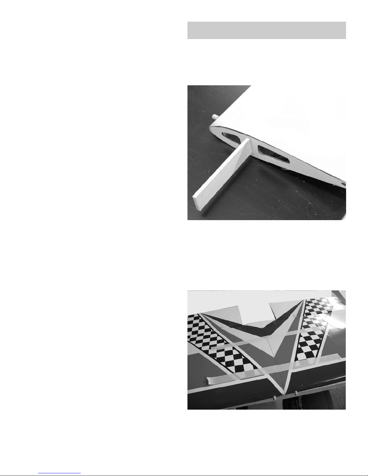
1. Trial fit the dihedral brace in the
slot on one wing. The wing is flat (no
dihedral) so the brace should fit
either way. Slide the other wing
panel in place and make sure the
joint in the center is closed.
2. Mix some 30 minute epoxy and
spread on all sides of the dihedral
brace, front back and edges.
7
Wild Stick 120
3. Spread epoxy on the root rib of
each wing panel. Use a thin scrap of
wood and work some of the epoxy
down into the slots for the dihedral
brace on each panel.
4. Use masking tape to hold the wing
panels firmly together while the
epoxy set. Lay the wing flat on the
floor or work bench while the epoxy
cures. Do not stand the wing on one
tip, all the glue will run to one end
and give you a poor joint.
5. locate the two 4mm x 40mm bolts
and two 4mm flat washers.
6. After the epoxy has cured, bolt the
wing in place on the fuselage..
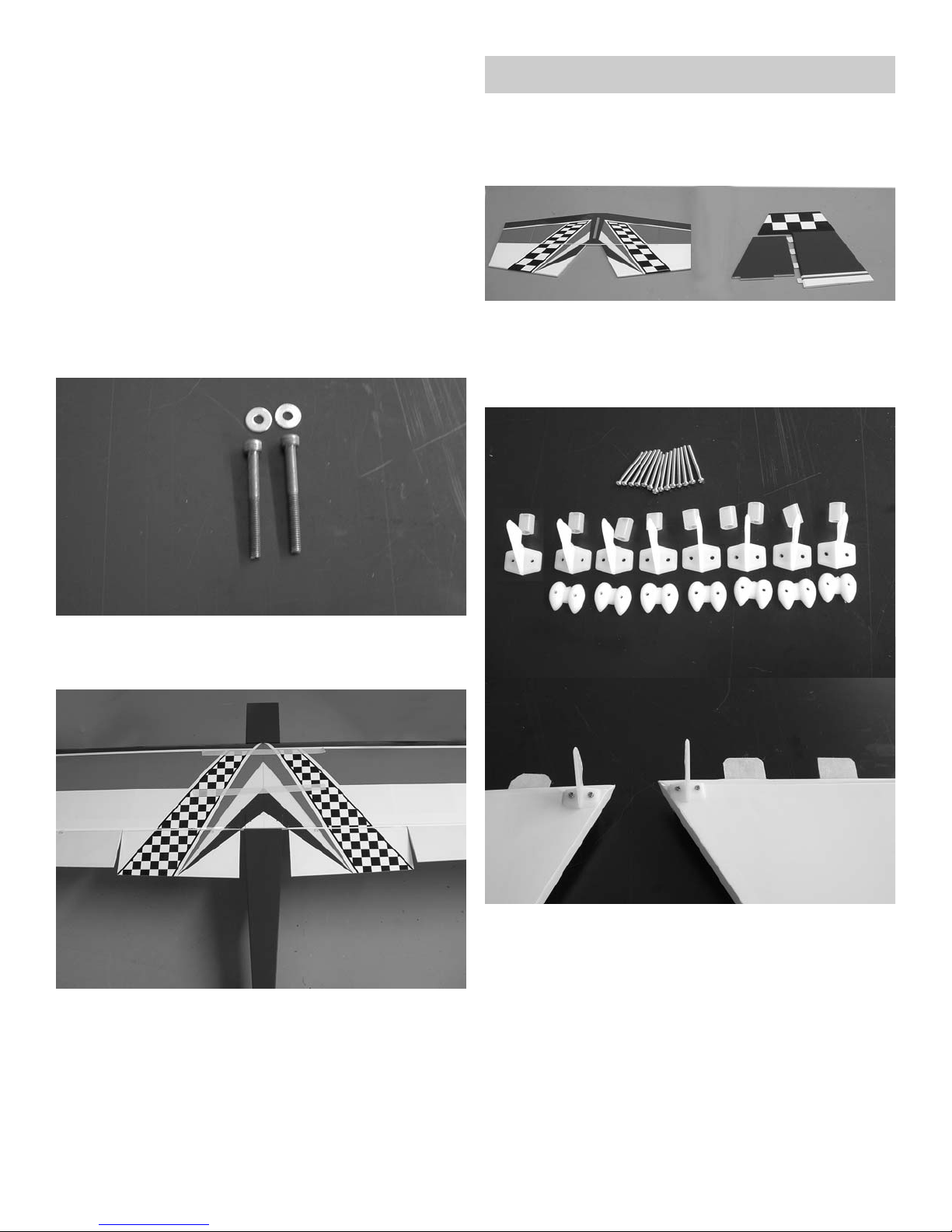
Tail construction
locate the following parts;
1. stabilizer with elevators
2. Fin with rudder
3. Nylon control horns
4. nylon nut plates
5. 2mm x 20mm screws
6. Silicone clevis keepers
1. locate the control horns on the
inside edge of the elevators on the
bottom side. make sure the holes for
the clevis are aligned over the hinge
line. Mark the location of the holes
and drill a 3/32” hole at the four
locations. use the 2mm screws and
nut plates to mount the control
horns.
8
Wild Stick 120
Align holes over
hinge line
2. Remove the elevators from the
stab and make sure all the hinges are
centered in the slots. To make sure
the hinges are centered, use a
straight pin in the middle of the hinge
when pushing the elevator onto the
stab.
3. Flex the elevator to the full
extent of its travel in one direction.
make sure the hinge line stays closed
as close as possible. Apply a drop of
thin CA to each hinge. Turn the stab
over, flex the elevator to the full
travel in the other direction and
apply glue to each hinge. go back and
apply another drop of glue to each
hinge.
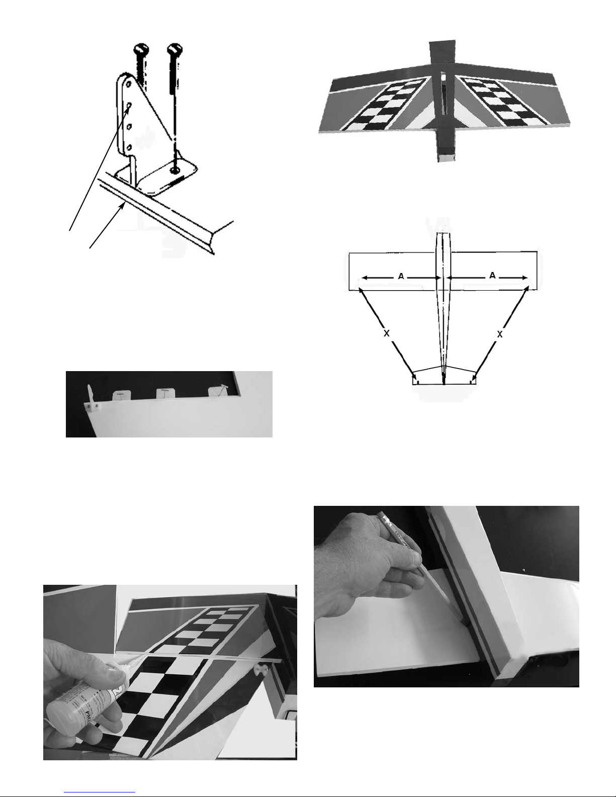
4. Set the stab in place in the slot on
the rear of the fuselage.
5. measure the stab to make sure it is
centered in the fuselage. Make sure
the slot for the fin in centered on
the fuselage. Move the stab until
dimension X-X are the same. This will
have the stab square to the fuselage.
6. When you have the stab square to
the fuselage, make a mark along the
side of the fuselage on the bottom of
the stab.
 Loading...