

Additional Items Needed
4-channel (or more) Radio Control Set
CA or Epoxy glue (large)
1/2oz. Thin CA glue
.40 to .61 (.90 4-cycle) R/C engine
13 running ft of covering material ( two
79”
rolls of material)
Paint (fuel-proof, quantity
depends on desired finish)
one 1-1/4” and two 3-1/4” Wheels
1/2” x8” x12” CG R/C Foam Rubber
Optional T
ools
CG Engine Test Stand (no. 293)
Propeller balancer
Combination prop/glow-plulg wrench
CG Hinge Slotting Kit (no. 269)
Engine Mounting Option
Drill & Tap, Size No. 43
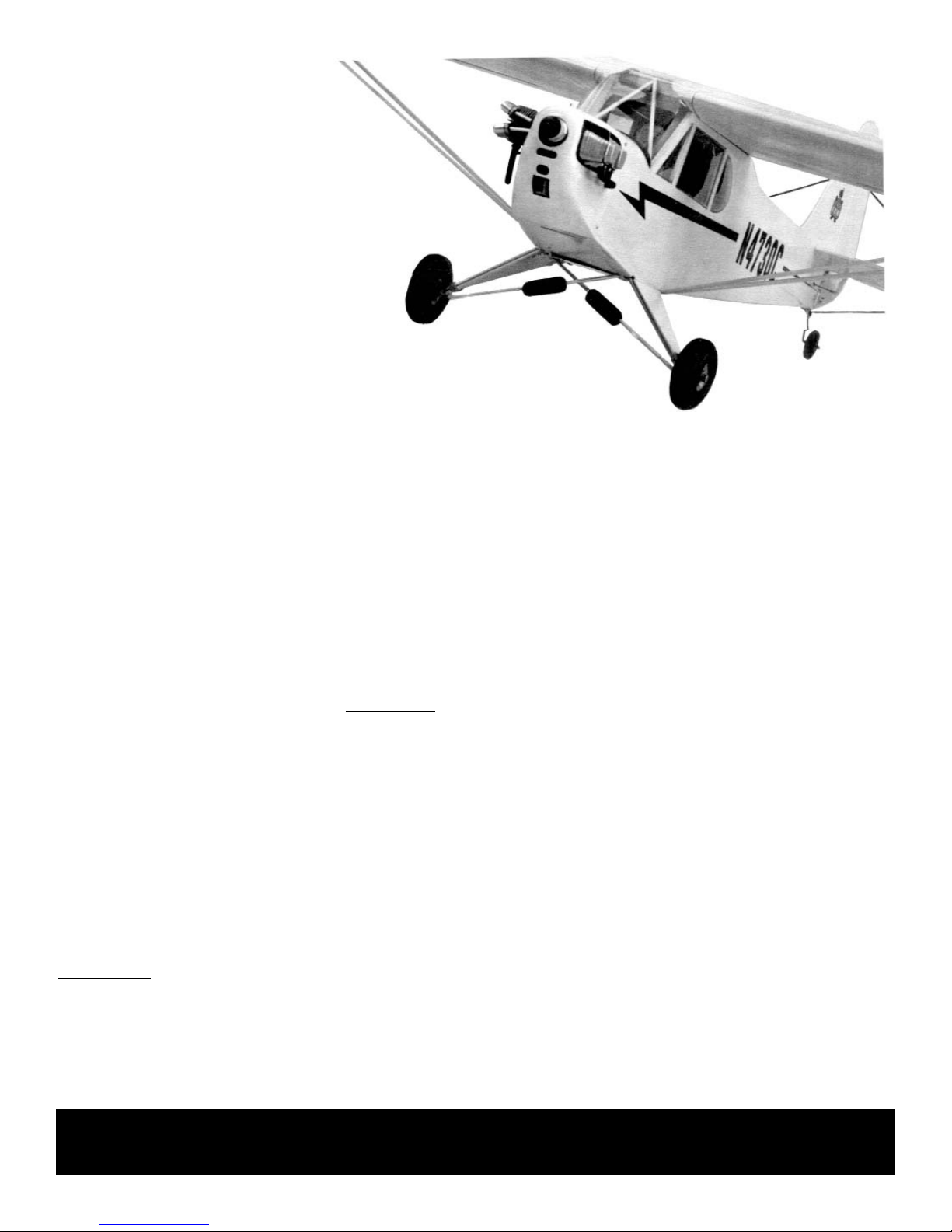
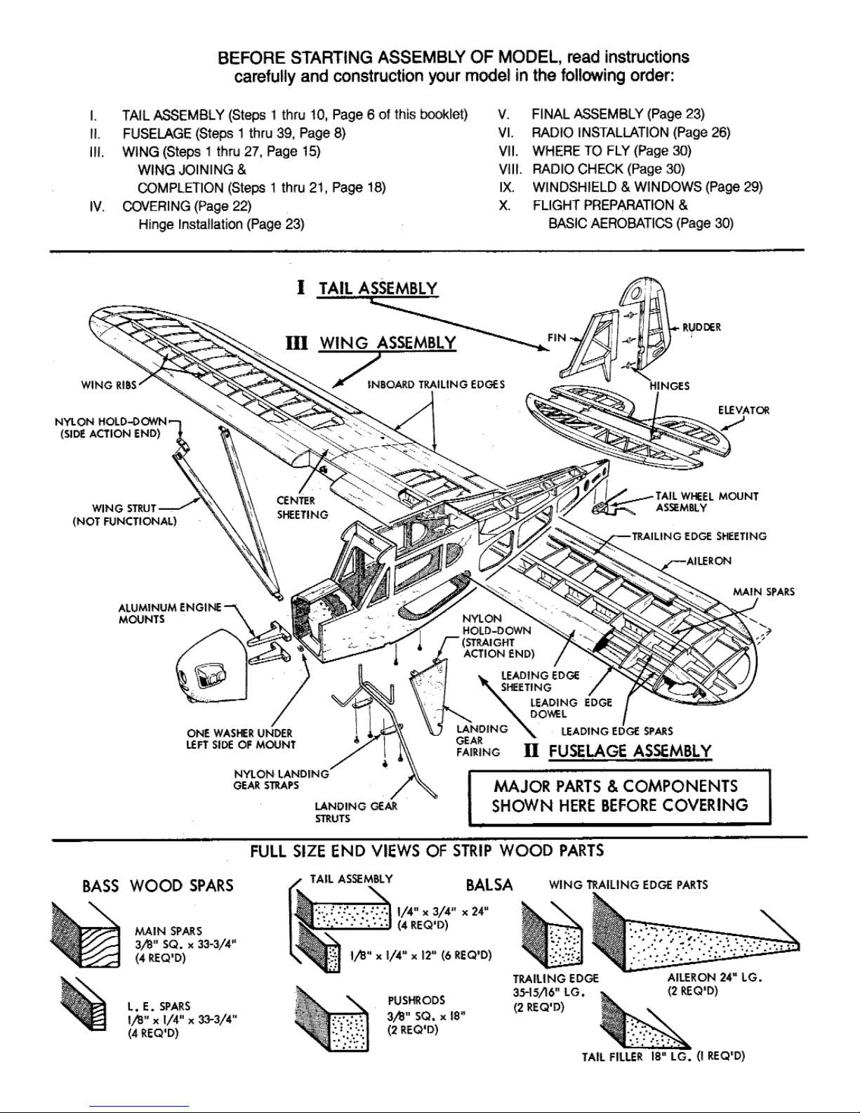
There really is nothing like a “Cub”! The C.G. version retains the honest, easy to fly qualities that made the full size airplane famous.
With the standard long wing, the model is a very graceful, realistic flyer. It’s aerobatic performance tends to be big,round, and slow.
Like the full size airplane, the model can be modified into an aerobatic version byshortening the wings. This “Clipped Wing” option
is a thrilling aerobatic machine that will provide outstanding performance, including point rolls, inside and outside
maneuvers, snaps and spins.
Building is easy, but to prevent simple mistakes, the step-by-step instructions should be followed. Many a modeler has made two
right fuselage sides instead of one right and one left as a results of not following the directions.
The Cub can be finished in any of the unlimited color schemes of of the original airplane.We show three popular types; standard,
sport, and military. Color scheme information's provided later in the instructions.
We’re sure that you will enjoy countless hours of flying fun with your Goldberg Cub, just as generations of pilots have had with
theirs!
Optional Parts
For Door Details
1/16” black CG Color-Stripe tape
Pilot figure (2” Scale)
“Pitts” type muffler (2-cycle only)
Small tube silicone caulk
Zap Formula 560 canopy glue
For optional “Military L-4” Scheme
WWII decals (various manufacturers)
Paint for Fuse Interior
Small spray can (gray)
Paint for Engine Detail
Artist’s acrylics, etc.
For simulating tail bracewires
1/16” nom. x36” elastic cord
Optional “Scale” Gear Struts
.025 x1/4” x2” brass strip
CG 1/16” Threaded Couplers (No.
217)
CG Mini-Snaps (No. 210)
5/32” O.D. dia. x 10” brass tube
3/32” O.D. dia. x 7” brass tube
Soldering iron, etc.
Tools & Supplies Needed
(You probably already have most of these)
Miscellaneous rubber bands
Wax paper or plastic wrap
Modeling knife or single edge razor blade
Sandpaper block & sandpaper; any grade 100
to 200, and any grade 240 to 320
A few dozen straight pins (“T” pins best)
Light power or hand drill & drill bits (sizes
1/16”,
3/32”, 1/8”, 5/32”, 3/16”, & 1/4”)
Three Allen wrenches (1/16” for #6 set screw
and 3/32” for #4 & 7/64” for #6 socket head
screws)
Flat building board (that you can push pins
into)
24” x 60”
Pliers
Small screwdrivers (1/8” and 3/16” blade tips)
Iron for applying covering (small household or
travel iron may be okay.
Masking, drafting, or scotch tape (for Holding
parts during assembly)
Carl Goldberg Products, Ltd.
P.O. Box 818 Oakwood, Ga. 30566 Phone 678-450-0085 Fax 770-532-2163 www.carlgoldbergproducts.com
©copyright 1985 Carl Goldberg Products, Ltd. Pt. #2077 issue #2 4-1-94
Instructions
Cub
2
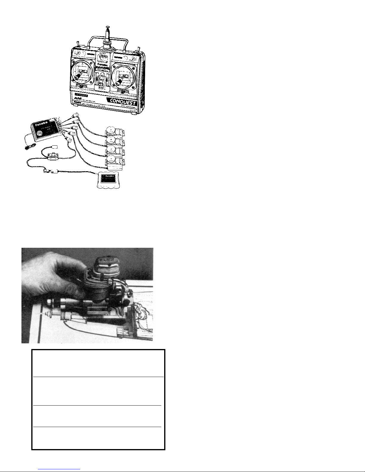
Digital proportional
Radio Control
One of many systems available,
please see your local dealer or
club for advice on selecting
your radio.
PROP AND FUEL TANK CHART
NUMBERS IN PARENTHESIS
REFER TO 4-CYCLE ENGINES
___________________________________________
FOR USE AND
ENGINE PROP TANK
SIZE SIZE SIZE
___________________________________________
.40-.51 10/6, 11/4, 11/6 8-10 OUNCE
(.40-.49) (12/6) (8)
___________________________________________
.60-.61 12/6 12 OUNCE
(.60-.91) (14/6) (10-12)
Selecting Radio Control Equipment
The Cub is designed for 4-channel radio control equipment. Many of the
radio systems now available feature “servo reversing” switches which allow you to
reverse the response of the servo. This feature simplifies radio installation and is a
worthwhile consideration when selecting a radio system.
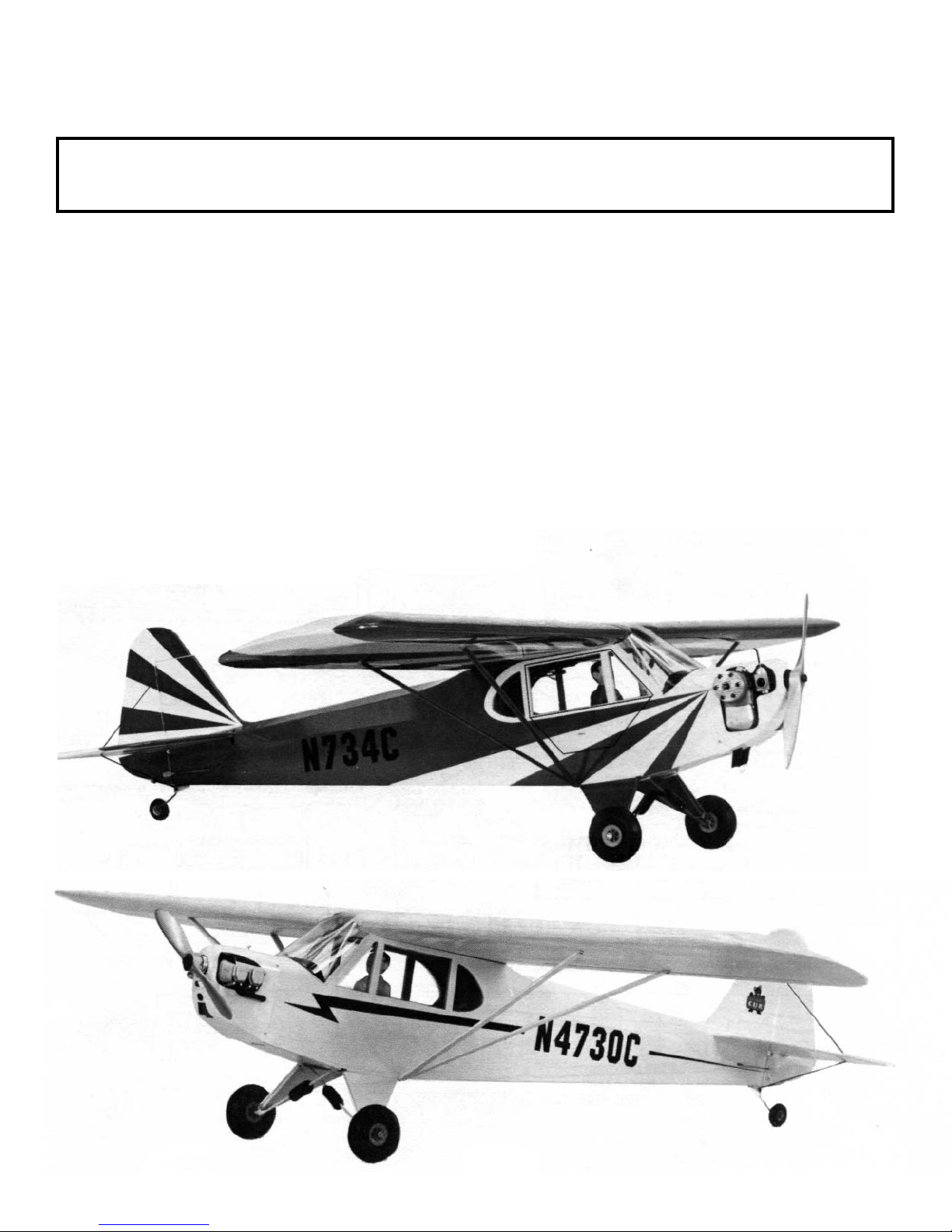
Engine & Propeller
The Cub flies well using any engine size from .40 to .61 (.90 4-cycle). cubicinch
displacement. If you live in a warm climate, or your flying field is approximately
3,000 feet or more above sea level, you should use a .49 engine or larger. The propeller size must be matched with the engine. For example, a .40 engine may use a
10” diameter prop, while a .61 uses 11”. Refer to the prop and fuel tank chart at
lower left.
Balancing your propeller helps to protect your radio from the damaging
effects of vibration. Good balancers are on the market, and generally are
easy to use. We recommend sanding or scraping the heavy blade on the
curved face rather than the flat face, and out near the tip. Try to maintain the normal
airfoil curvature. And avoid scratches which might cause the prop to break.
Adhesives
All our test models were built using cyanoacrylate glue(CA) which is
specially formulated to firmly glue the plywood, hardwood, plastic, and balsa used
in your Cub, and we strongly recommend it. Other good glues to use are“15 Minute
Epoxy” or Aliphatic Resin. They will, however, add considerably to the assembly
time required (they dry a lot slower than CA). Also, Aliphatic Resin does not glue
plastic, so you will need one of the adhesives mentioned above (or similar) for the
plastic parts.
IMPORTANT!
In a few specific areas of assembly we suggest the use of thin type of instant glue (
CA) for example, sheeting the leading edge of the wing.
Other than when specifically recommended, these thin types of glue
should not be used since they do not glue plywood adequately and also
require that your work must be near perfect. Be careful when using instant glue to
install windows, as applying too much glue can sometimes cause fogging to occur.
This can be easily wiped off with a damp rag. A sure way to avoid fogging is to use
either epoxy or Zap Formula 560 canopy glue.
After you have finished gluing the model together, go back and re-glue all the
joints for added strength, and just in case some joints may have been
missed the first time. Be careful not to use too little glue. Too little leaves a
model weak. Since CA almost eliminates waiting for glue joints to dry, you can
work straight through and finish each assembly by following the step-by -step building sequence. If you use epoxy, you can save time while waiting for one assembly to
dry (the stabilizer, for example) by turning a few pages ahead and starting another
part (the fuselage, perhaps). Check-off boxes are provided at each step so you can
tell at a glance what steps you have completed.
Tack-Cementing. Sometimes it is necessary to temporarily glue a part
in place that must later be removed. To provide for easy removal of the part
without damage, it should have been glued in place using only a small dab of glue.
This is referred to as “tack-cementing” later on in the instructions.
Using Cyanoacrylate Glue. CA lets you b uild almost as fast as your hands
can press parts toghether! When pressed into a very thin layer, it sets almost instantly. So be careful, read instrluctions thoroughly and use check-off boxes to avoid
errors (like building two right-hand wings-instead of a left and a right)! CA allows
only for momentary positioning of parts. So be sure to trial fit parts toghether to
check fit and placement before applying glue. After its initial bond, CA continues to
strengthen. CA sets up a bit slower with plywood and hardwood, so hold such joints
together a little longer than you would for balsa. CA in corners takes a while longer
to dry because of its not being a thin layer. The tendency for all instant glues to set
slower on hardwood or plywood and when in a thick layer can be elilminated by
using Kicker, an accelerator for cyanoacrylate glue. Kicker bridges greater gaps,
speeds up slow bonds, and provides strong joint fillets.
Using Epoxy. Epoxy comes in two parts which need to be mixed before
using. Paper cups and wood coffee stirrers are useful for ixing. When
buying epoxy, check the package to see how long it takes to set (some formulas\
set in 5 minutes, others may take hours). We recommend 15 minute
3
epoxy. Disposable wood strips, cotton swabs, cheap stiff bristle brushes, or acid brushes from auto stores make good applicators.
Because epoxy is so thick, it’s easy to apply too much. If you use epoxy to build the entire model be especially careful to use sparingly
when assembling fin, stabilizer, and wing.
Caution
Some people may experience allergic reactions when exposed to fumes from instant glue or epoxy. This is very rare. However, it is always
important that such glues, and also paints, thinners and solvents, be used with adeqquate ventilation to carry fumes away.
Windshield
The Cub windshield was carefully designed to realistically duplicate the distinctive lines of the original, yet still be easy to install. For good final
appearance, follow instructions carefully, especially those dealing with removing scrap plastic from windshield base and its’ installation. If tinted
windows are desired, do not try to dye them (the plastic does not dye well).Instead, we recommend “transparent” spray enamels be carefully
applied to the inside window surface (they are not fuel proof).
Covering The Model
The full size Cub is of wood and metal construction, which is covered with fabric. The fabric is then painted. For your model, fabric types of covering duplicate the fabric appearance of the full size airplane quite realistically. There are many good covering materials available that have good
resistance to tearing and punctures. General information on applying iron-on covering can be found on page 22. Because of specific differences in
the application of various brands of covering, make sure instructions have been provided by the manufacturer of the covering you select.
Clipped Wing Option
The shortened wing for this option is accomplished by cutting the spars, leadings edges, etc. to the shorter lengths shown on the plan. This is
fully described at the beginning of the wing assembly.
4
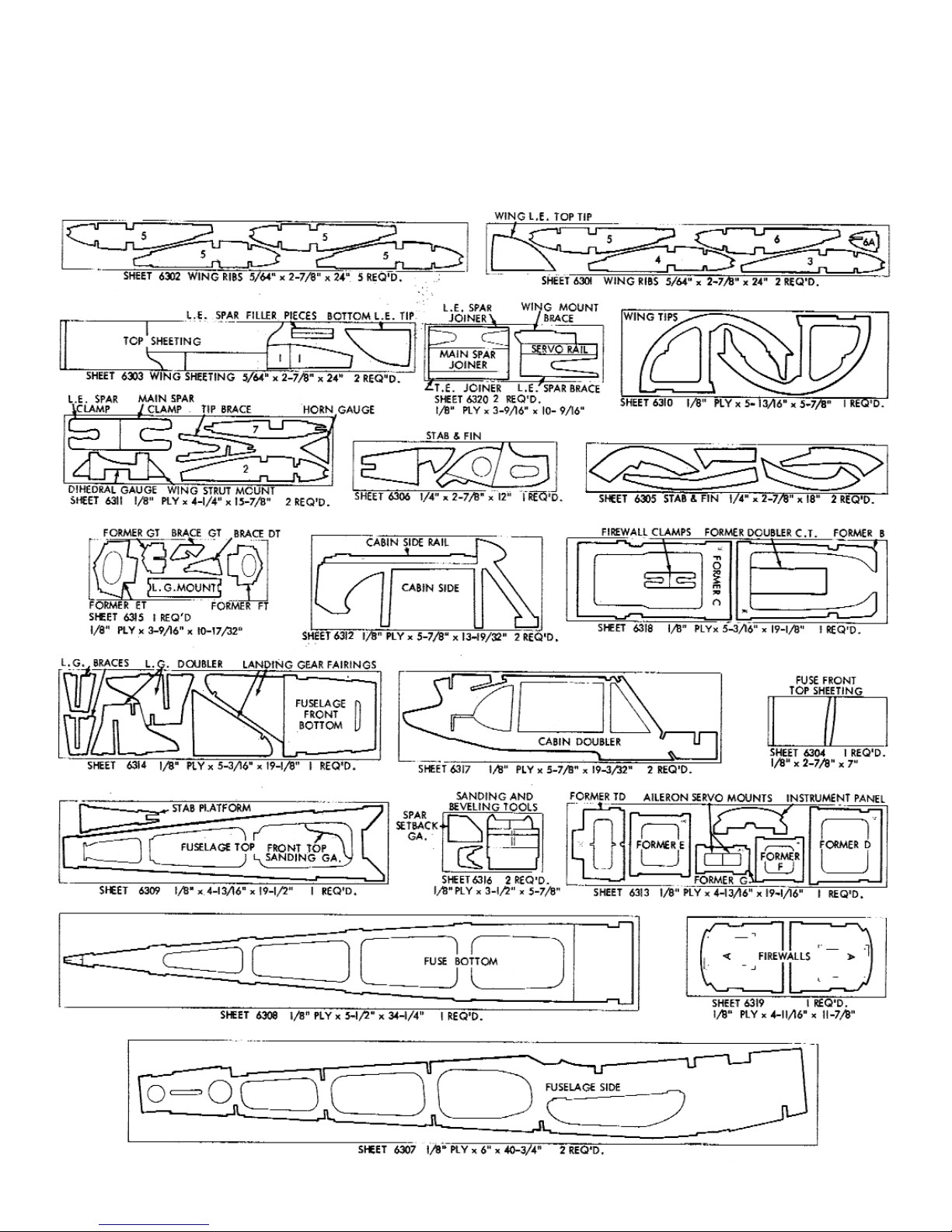
Be careful when removing parts (such as fuselage sides)
from die-cut sheets. Long parts are fragile until glued into a
structural unit. If necessary, use a razor knife or razor saw
to assist in the removal of parts from sheet. Sometimes a
little trimming and sanding can improve parts where
desired. Save scrap until model is completed, in case you
should miss a part. Scrap is used also in some building
steps on the plan. Other easily recognized parts, such as
engine bearers, are not shown here.
Wood Parts Identification
5
6
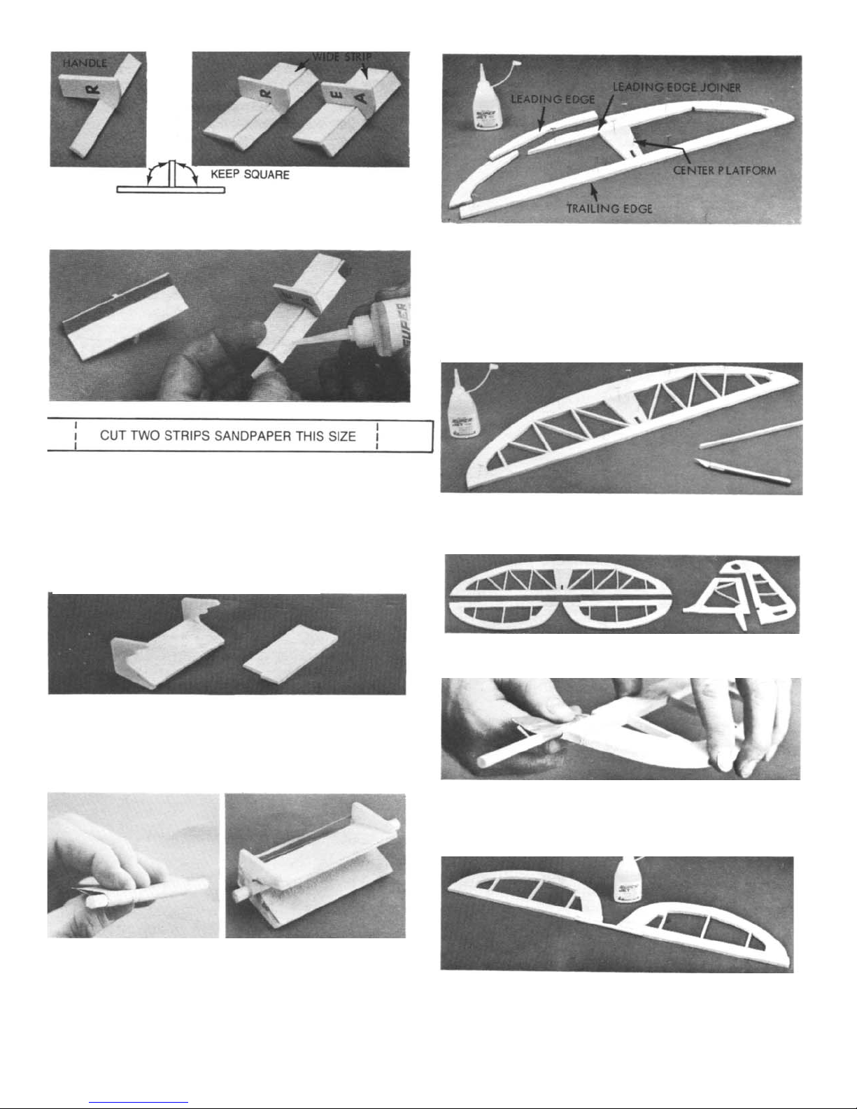
1. First, glue narrow strip to handle, keeping them
square, as shown above left. Then glue wide strip to
handle and narrow strip, again keeping things square.
2. Cut two strips of 100-200 grit sandpaper to size shown
above. Tack-cement sandpaper to tools as shown.
Die-Cut Sanding Tool
1. Glue one strip into handles notches keeping them
square. Then glue remaining strip to other half of handles.
2.
Cut one piece of 100-200 grit sandpaper to size of
2-1/4” x 3”.
Center 1/4” dowel over grit side of sandpaper. Roll
sandpaper around it as shown above left.
Slide dowel and sandpaper into tool and hold with
rubber band as shown at right. Glue sandpaper to tool.
1. From 1/4” x3/4” balsa stick material, make stabilizer
(stab) trailing edge (T.E.). Cut balsa carefully to match
with plan at ends. Pin in place.
Position and pin die-cut center platform over plan. Cut
stab leading edge (L.E.) joiner from 1/4” x 3/4” balsa to
match with plan and pin in position.
Assemble die-cut curved L.E. segments to form stab
outline, glue all parts together.
2. From 1/8”x 1/4” strip balsa, cut all trusses to size over
plan. Trim to fit well-don’t force into place. Glue in place.
Let dry thoroughly.
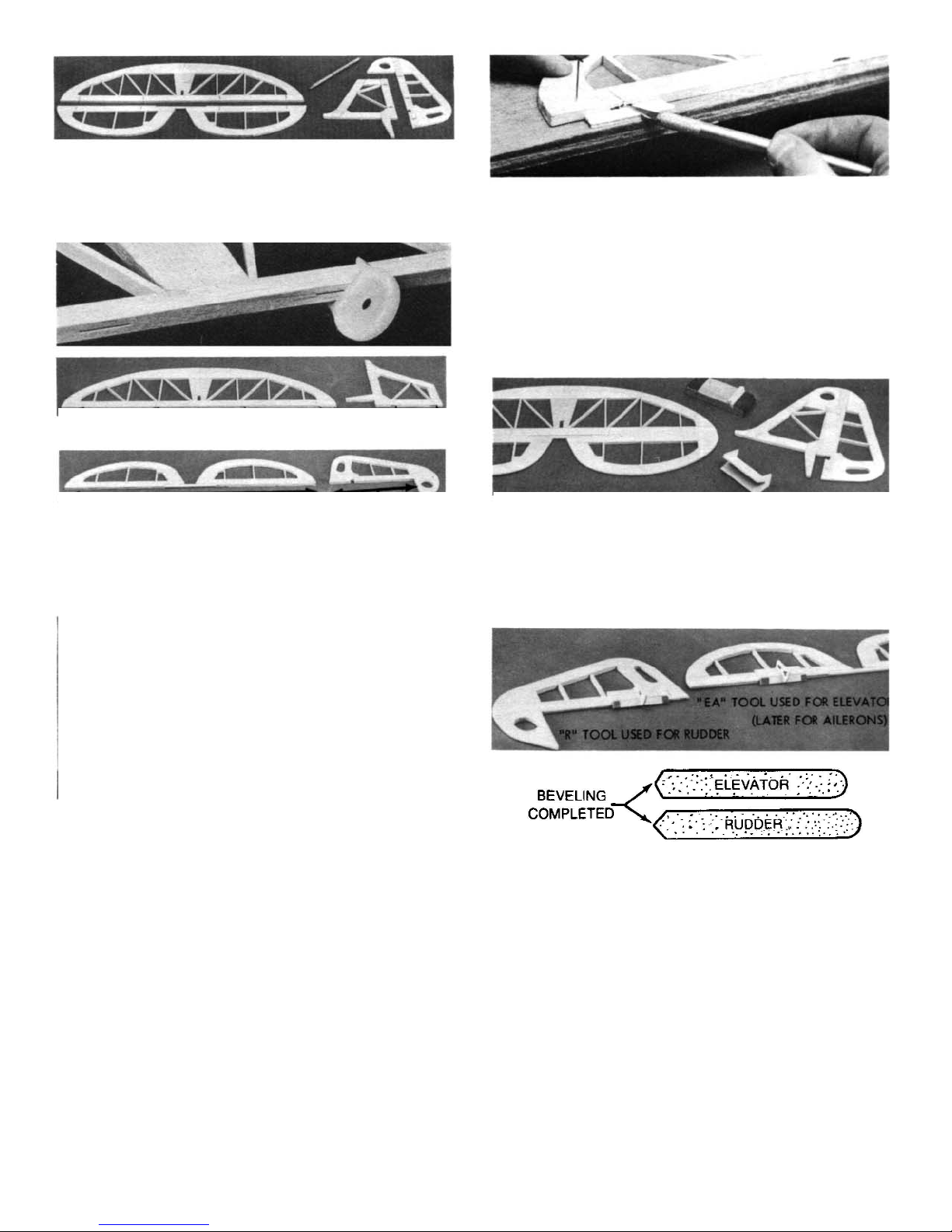
3. Assemble elevator halves, fin and rudder in same
manner as stab, using die-cut and stick parts.
4. Wrap 100-200 grit sandpaper around 1/4” x4-1/2”
dowel. Carefully sand recessed area in elevator L.E. so
dowel will fit flush with front of elevator.
Repeat for other elevator half.
Carefully align L.E.’s of elevators over plan and pin in
place. Join them with the 1/4” dowel, glue it securely in
place! Let dry thoroughly.
7
5. Place fin and rudder over plan and mark hinge location
Mark hinge locations for stab and elevator.
On stab & fin, mark center lines at hinge locations
On elevator & rudder, mark center lines along entire L.E.
6.
Using CG Center-Line marker provided, mark center-
lines along edges of parts as shown above. Tilt marker so
guide pegs touch the wood., then lightly pass the marker
back and forth. Point will scribe center line.
Using scrap ply from “sanding tool” sheet as a shim,
cut slots for hinges as shown. Sand ply if necessary so
blade cuts on center.
8.
Repeat this method in step 7 for fin and rudder.
First break corners with the sanding block. Then,
follow with stab sanding tool, rounding off all outside
edges except bottom of fin and the rudder L.E. Blend stab
and elevator at tips.
IMPORTANT! The hinges are not
9. Using a sanding block, flat sand stab, elevator, fin
and rudder, smoothing out surfaces.
Using no glue, TEMPORARILY attach elevator to stab
and fin to rudder with hinges in place. Hold parts together
with tape.
10. Remove tapes and separate elevator and rudder from
stab and fin.
Tape T.E. of elevator and rudder to work surface,
using
appropriate beveling tool, sand L.E. to center line.
Turn parts over and repeat beveling for other side.
THIS COMPLETES THE TAIL ASSEMBLY
CONSTRUCTION.
8
II FUSELAGE ASSEMBLY
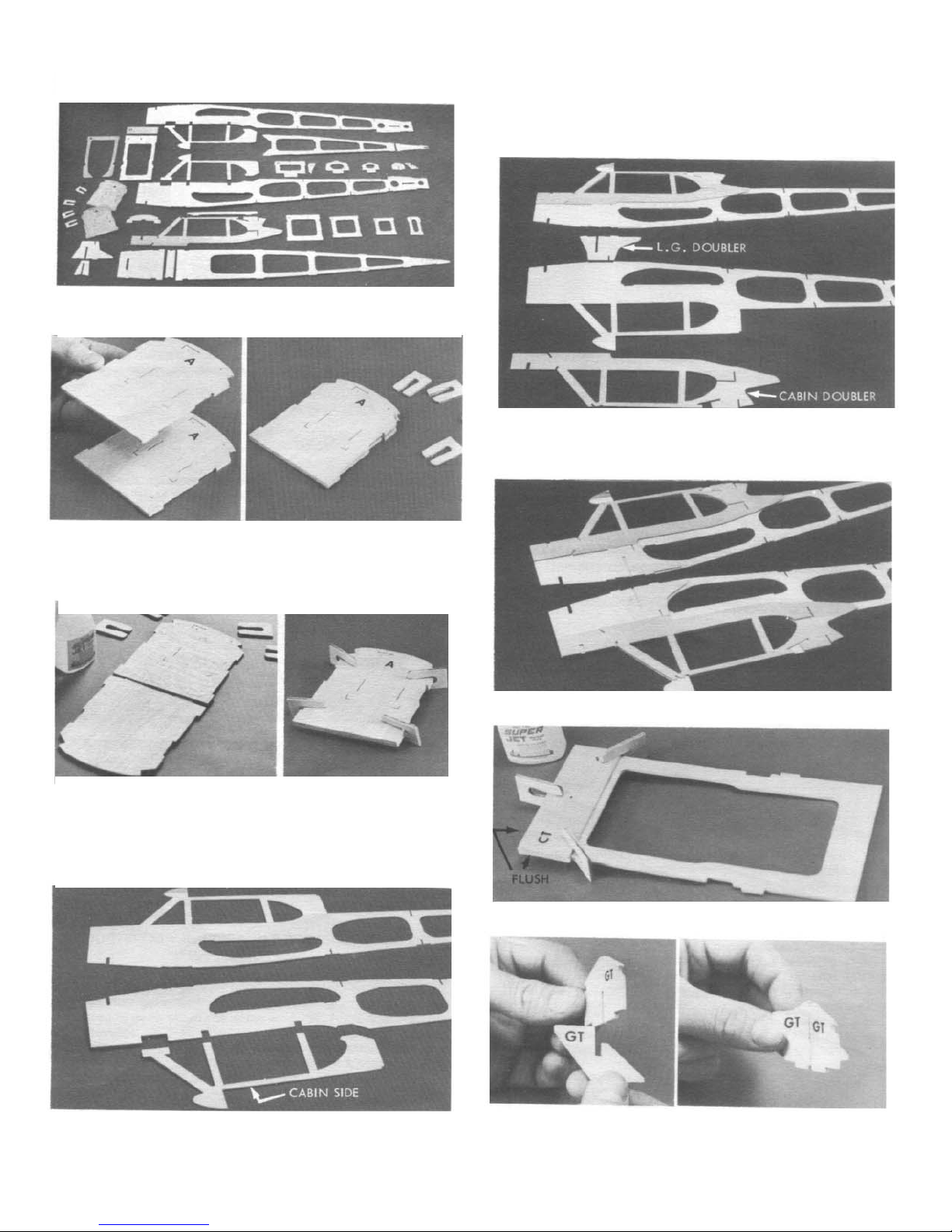
1. Carefully remove all fuselage (fuse) parts from die-cut
sheets. Lightly sand any rough edges.
2. With side stamped “A” facing out, position two 1/8”
ply formers (firewall) together, matching all edges. To hold
them in alignment, tape them securely together along one
edge as shown at right. Have four ply clamps ready for
next operation.
3. Open firewalls and apply a liberal amount of glue to
one part as shown at left.
Keep edges aligned as you close firewalls and tape
opposite edges together, squeeze firewalls together using
die-cut clamps. When dry, remove clamps and tapes; set
clamps aside for use later.
Temporarily position cabin sides in notches. Check
f it and ;placement of parts before gluing.
Glue cabin sides to fuse.
Temporarily position cabin and landing gear (L.G.)
doublers on fuse side, checking fit and placement before
gluing.
Glue cabin and L.G. doublers in place.
5.
Glue former doubler “CT” to former C.
Slide brace GT fully into former GT. Hold brace
square to former and glue.
9
Glue former brace DT to rear of former DT.
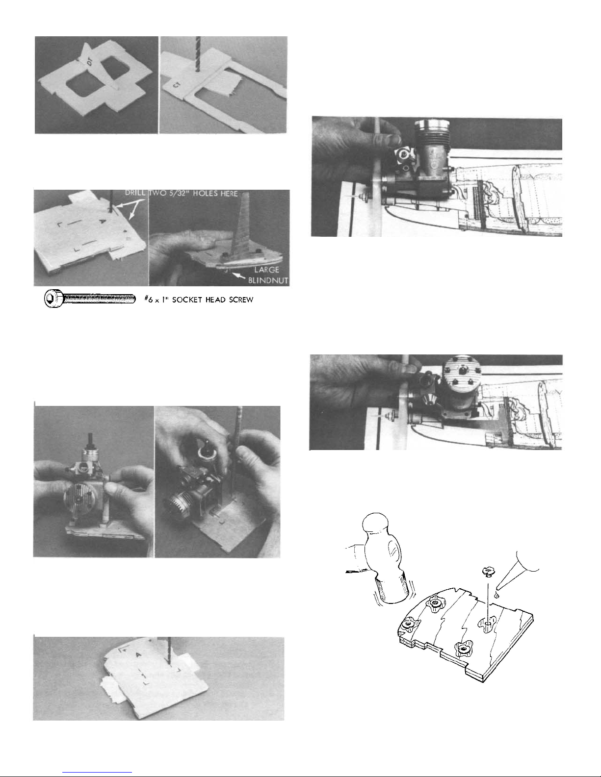
Drill a 1/4” diameter hole through CT & C at punch
mark location.
6. Drill two 5/32” diameter holes through firewall at
upper punch mark locations (place scrap wood under
backside while drilling to avoid splitout).
Temporarily install one of the motor mounts, using (2)
#6x1” socket head bolts and blindnuts. Do not pull the
blindnuts into firewall at this time, since they may need to
be removed at a later time.
7. Position the engine between both mounts, holding it
vertical to firewall and parallel to mounts. Spread mounts
apart to match engine mounting holes (there are two
stamped reference lines for positioning mount directly
under the upper one.)
Mark straight down through holes in lower mount.
8. Remove engine and mounts. Drill two more 5/32”
holes at lower mount location.
NOTE: Your kit may include an non-updated plan. The
1/4” ply motor mount extension is no longer needed with the
change to the fiber filled engine mounts now included with
the kit. If you have an older plan, please disregard any
reference to the ply extension.
9. Mount propeller on your engine. Position engine over
fuse top view on plan and compare it to the installation
shown. Back of your prop should protrude 1/8” to 1/4”
beyond the cowl front as shown on the plan. Hold engine
in this location.For long 4-cycle engines, check for at
least 1/8” clearance between engine rear and firewall; to
obtain this clearance the engine may have to be shifted
forward as required. Measure the distance from the
engine rear to the firewall. Write this measurement down,
it will be used later for engine mounting.
10. Position one engine mount, butting its rear flange
against the firewall location shown on the plan. Observe
how the front engine mounting holes relate to the engine
mount.
11. Insert the four blind nuts into the holes on the BACK
side of the firewall. CA glue the nuts to the ply and seat
them into the firewall with a hammer.
10
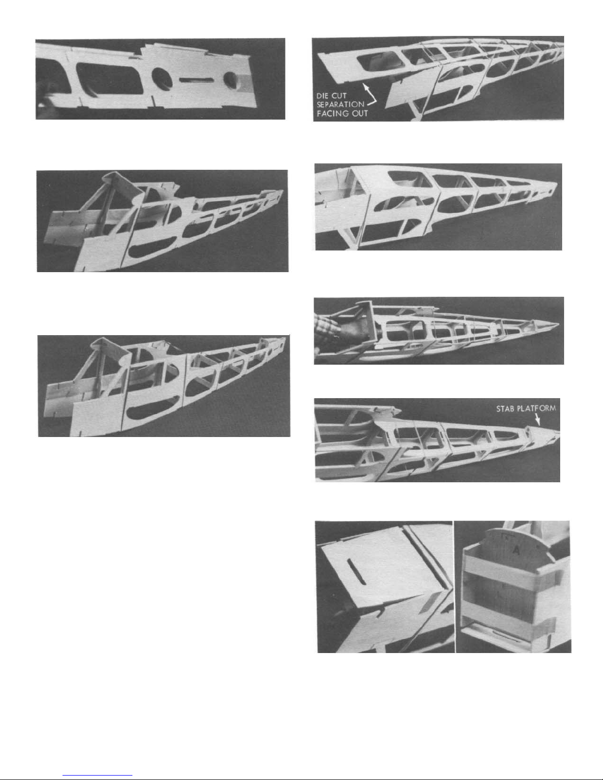
12a. Place fuse sides one on the other, tape rear
together around the back end. Spread fuse fronts apart,
and plug former “C” into holes in body sides. Hold parts
together with a rubber band.
12b. Hold fuse tail end up, carefully spread fuse rear
open,and plug former “G” in place, hold with a rubber
band. Working towards front, install formers “F”, “E”
and “D” in same manner, using rubber bands to hold
parts.
12c. With die-cut separation facing out, insert bottom
sheet under rubber bands at former “C”, and work it
towards tail, slipping it under bands as you go.
12d. Lock tabs at sides and ends of bottom sheet into
corresponding notches in fuse sides. Hold parts with
tape.
12e. Working through former C, position top sheet in
same manner, sliding it towards rear.
12f. Position stab platform between fuse ends, and hold
parts in place with tape or rubber bands.
13. Position front bottom sheet and tape it securely to
fuse at rear only as shown.
14.
Install firewall and pull fuse fronts toghether with tape
as shown.
 Loading...