

Cargo Floor SLC Series, CF500 SLC, CF100 SLC, CF3 LP-2, CF500 Power speed Technical User's Manual
...Page 1

Technical user manual SLC General
www.cargofloor.com
www.cargofloor.com Page 1
Version 01 / July 10th, 2017
GENERAL
CARGO FLOOR USER MANUAL
We would like to introduce to you the right operation of our Cargo Floor system with the help of the
following data and we also want to point out to you the steps that you can take to solve malfunctions.
Please read and follow our instructions carefully so that the Cargo Floor system will give you reliable and
trouble free service for many years and health and safety is secured.
If the Cargo Floor system does not operate at all (or properly) after following the instructions, please do
not hesitate to contact your nearest agent, who will with no doubt assist you in solving the problem.
Please pay particular attention to the contents of the “Important recommendations and guidelines” on
page 2 and further!
The measurements given in this instruction start with the metric system after which between brackets [0]
the US/imperial measurement is mentioned.
TABLE OF CONTENTS
GENERAL ................................................................................................................................................ 1
Important recommendations and guidelines .......................................................................................................... 2
Health and safety short list ..................................................................................................................................... 5
Emergency stop ..................................................................................................................................................... 5
Start up check list before operation (unloading / loading) ...................................................................................... 5
Stickers ................................................................................................................................................................... 6
How to check the chosen loading/unloading function ............................................................................................ 8
Modular operating possibilities ............................................................................................................................... 9
Wet kit information ................................................................................................................................................ 10
Hydraulic start-up check list for the Cargo Floor system ..................................................................................... 11
Identification plate ................................................................................................................................................ 12
Cargo Floor technical specifications .................................................................................................................... 13
Maintenance instructions ...................................................................................................................................... 14
Adjustment of the threaded rod of the control valve ............................................................................................ 15
Warranty conditions .............................................................................................................................................. 16
A-CONTROL .......................................................................................................................................... 18
Control valve......................................................................................................................................................... 18
Loading – unloading function ............................................................................................................................... 18
Hydraulic circuit diagram A-control ...................................................................................................................... 19
Troubleshooting A-control valve ........................................................................................................................... 20
B-CONTROL .......................................................................................................................................... 21
Control valve......................................................................................................................................................... 21
Loading – unloading function ............................................................................................................................... 21
Function of B-control Switches ............................................................................................................................. 22
App receiver ......................................................................................................................................................... 23
Remote control (CF TX) Transmitter .................................................................................................................... 23
Manual override .................................................................................................................................................... 24
Electrical circuit diagram B-control ....................................................................................................................... 25
Hydraulic circuit diagram ...................................................................................................................................... 26
Troubleshooting B-control valve ........................................................................................................................... 27
E-CONTROL .......................................................................................................................................... 28
Control valve......................................................................................................................................................... 28
Function of E-control switches ............................................................................................................................. 28
App receiver ......................................................................................................................................................... 30
Remote control (CF TX) Transmitter .................................................................................................................... 30
Manual override .................................................................................................................................................... 31
Electrical circuit diagram E-control ....................................................................................................................... 32
Hydraulic circuit diagram ...................................................................................................................................... 33
Choke ................................................................................................................................................................... 34
Troubleshooting E-control .................................................................................................................................... 35
CONTACT DATA ................................................................................................................................ ... 36
Page 2

Technical user manual SLC General
www.cargofloor.com
www.cargofloor.com Page 2
Version 01 / July 10th, 2017
IMPORTANT RECOMMENDATIONS AND GUIDELINES
Before putting the Cargo Floor loading and unloading system into operation, follow the recommendations
provided below and check the specified checkpoints to avoid damage to the Cargo Floor system and the
vehicle.
Please review the important instructions before operating the Cargo Floor system and loading cargo into
the vehicle. Likewise, before loading cargo, check the operation of the various control switches/valves to
familiarise yourself with how the system works. We strongly recommend that you perform these checks
when picking up the vehicle from the dealer so that your skilled supplier can answer your questions and
provide you with any necessary advice or guidance you may require.
Important:
Always check that the selected loading or unloading direction is actually activated and occurring!!
If the system fails to start, turn off the Cargo Floor system and the hydraulic pump and follow the
recommendations and guidelines provided below. Do not repeatedly try to start the system as this
may result in damage to your Cargo Floor system and/or vehicle.
After use, turn off the Cargo Floor system and hydraulic pump. Set switches to the "0" position and
the lever in neutral.
In case of doubt or uncertainty about these recommendations and guidelines, always contact your dealer
or an official workshop.
The Cargo Floor system comes standard with an operating manual, but is this has not been supplied,
please contact your dealer or download it from the official Cargo Floor website: www.cargofloor.com,
download.
A) Always open the vehicle's doors before turning on the hydraulic pump. Note! Build-up of pressure
against the doors can open them with force. Also some of the cargo can fall out of the vehicle by
itself after opening the doors, therefore KEEP CLEAR AT ALL TIMES, product could fall on top of
you! Both could result in damages and/or injuries! It is always advisable to use the pneumatic door
lock, if provided.
B) 1. Check that the vehicle's (quick-detachable) couplings are properly connected to the P (Pressure
line) and the T (tank/return line). Also check that the couplings are fully tightened or slid completely
into each other.
IMPORTANT: the pressure and return line connectors may not be reversed or exchanged to
prevent dirt or water from entering the lines when connecting them!
2. Before connecting, check that the non-return valves can open easily (check: the non-return
valves should open easily when pressed with the finger, if not, potential pressure build-up in the
hydraulic lines may be preventing the system from starting).
NOTE: Incorrectly connected or unopened hydraulic couplings will cause serious damage to the
Cargo Floor system and the vehicle.
C) The vehicle (pump) must be fitted with a pressure relief valve that is set at the maximum pressure
according to the system, see the technical specs. If fitted, check that the dual-function lever
(function: tipper/Cargo Floor) is in the Cargo Floor position. Pressure may not exceed the
maximum adjusted and allowable operating pressure of the Cargo Floor system. An incorrectly
adjusted pressure relief valve can cause damage to the Cargo Floor system and the vehicle.
D) During operation, the (hand)brake of the vehicle must always be applied. You must, however,
move the vehicle forward on time to unload it quickly in order to prevent unnecessary strain and
wear to the floor and the vehicle.
E) Use of a wireless remote control is permitted only if it is fully tested before the start of each loading
or unloading operation. Always check if the function you have selected is actually activated and
taking place. If, for example, you have accidentally pressed the load function when you actually
meant to press the unload function, irreversible damage may occur to the Cargo Floor system and
the vehicle.
F) During operation of the Cargo Floor system, all existing STOP and control knobs/levers must be
freely accessible.
Page 3

Technical user manual SLC General
www.cargofloor.com
www.cargofloor.com Page 3
Version 01 / July 10th, 2017
G) The pressure filter element needs to be replaced at least once a year. If the couplings between the
vehicle and the Cargo Floor system are regularly removed, it is advisable to check the pressure
filter for dirt build-up and replace the pressure filter element more often, if necessary. If provided,
also check the return filter (not supplied with the Cargo Floor). Failure to replace a filter element on
time may cause damage to or malfunctions in the Cargo Floor system and the vehicle.
H) Moving parts must be shielded. Always maintain at least 10 meter [30’] distance from the Cargo
Floor system when it is in operation.
I) In the event of malfunctions/maintenance work, you may approach the Cargo Floor system only if
all equipment, including the hydraulic pump, have been shut off, and the Cargo Floor system and
the electro-hydraulic aggregate have been disconnected from the power supply and pump.
J) Regularly check and, if necessary, tighten any loose bolts that secure the aluminium floor profiles
to the Cargo Floor system. All such checks can simply be performed inside the vehicle itself by
qualified personnel. The Cargo Floor system must, however, be turned on in unloaded condition
and the person performing the check must place his finger half on the floor profile and half on the
bolt. There should be no appreciable movement/space between the floor profile and bolt. Failure
to check these bolts may lead to damage to the Cargo Floor system. During this check, a second
person must also be present to switch off the Cargo Floor system.
K) Check that the minimum required amount of oil is present 150 liter [40 US gallon]. Too little oil in
the hydraulic tank will cause damage to both the pump and the Cargo Floor system.
L) Do not allow the number of strokes to exceed the maximum allowable 16 power strokes per
minute. Only a CF500 SLC Power Speed Cargo Floor system may deliver up to 23 beats per
minute. A higher number of power strokes can cause damage to the Cargo Floor system and the
vehicle.
M) Hydraulic lines, couplings and hoses with very small diameters will cause damage.
N) If the Cargo Floor system fails to start or operates incorrectly, the Cargo Floor system and the
hydraulic pump must be shut down immediately. Subsequently, check all the checkpoints before
switching the pump and the Cargo Floor system back on. To prevent the oil from overheating,
regularly check the oil temperature by CAREFULLY and CAUTIOUSLY touching the line and or oil
tank. If either is too hot to the touch, stop touching them right away. WARNING: TOUCHING
OVERHEATED OIL AND COMPONENTS CAN CAUSE BURNS!
O) The cause of failure or malfunctioning of the Cargo Floor system may also be due to other
hydraulic components that may or may not be connected to the same hydraulic circuit of the Cargo
Floor system.
P) Jamming of the floor profiles caused by the transport of abnormal loads and or the freezing of the
floor or of the product to the floor may result in damage to the Cargo Floor system and the vehicle.
Recommendation: in the event of freezing, stop the system and try to find a hall (heated area) to
allow the product to thaw.
Q) Because the electrical power supply of the Cargo Floor system is often connected to the lighting
circuit of the vehicle, it is advisable to turn on the lighting throughout the operation of the system.
R) Maintenance and repairs to the Cargo Floor system may be only performed by qualified personnel.
Use only original Cargo Floor components to ensure maximum reliability and long service life.
S) Maximum cargo weight is subject to the limits set by law and applicable regulations. Even if the
system can transport heavier loads, the law determines the maximum limit. Excessively heavy
cargo can cause damage to the Cargo Floor system and the vehicle.
T) Check that the correct type and quality of hydraulic oil is used. The use of incorrect oil type may
cause damage to the Cargo Floor system and the pump.
U) Check the vehicle for correct voltage. Make sure there are no open electrical connections. A faulty
electrical system can cause damage to the Cargo Floor system and the vehicle.
V) Check that the bulkhead, if present, is functioning smoothly and properly. A properly functioning
bulkhead ensures that the product is unloaded in a clean and quick fashion. A malfunctioning
bulkhead may extend the unloading time and cause damage to the vehicle.
W) Use of the Cargo Floor system by unqualified personnel can cause damage to the Cargo Floor
system and the vehicle.
X) Excessively high oil temperatures will cause damage to the Cargo Floor system and other
hydraulic components, such as the pump.
Page 4

Technical user manual SLC General
www.cargofloor.com
www.cargofloor.com Page 4
Version 01 / July 10th, 2017
Y) It is at all times advisable to stop the Cargo Floor system when all the piston rods are retracted.
This is usually the case when the floor profiles are positioned towards the unloading end (vehicle
doors). Unretracted piston rods may cause damage to the Cargo Floor system.
Z) To prevent damage to the floor profiles, exercise caution and limit the dump height as much as
possible. The transport of unauthorised goods, such as aggressive, corrosive, hot, hard, sharp and
viscous materials may cause damage to the Cargo Floor system and the vehicle. Avoid loading
and unloading sharp objects. Loads that are softer than the hardness of the floor profiles will
extend the service life of your system; if in doubt, use a protective cloth or consult your dealer.
AA) Forklift trafficable. In principle, the floors are completely trafficable and can be driven over by
forklifts, but always consult your dealer for advice on the maximum loads allowed on your vehicle.
Overloading will cause damage to the Cargo Floor system and the vehicle.
BB) Always return emergency control(s) to their original non-activated position after use.
CC) During the operation of the system, test the temperature of the oil by touching the side of the tank.
If the oil is so hot that you cannot continue to touch the tank, switch off the pump to allow the oil to
cool off and determine what is causing the overheating. Stop loading or unloading if the oil is too
hot, as this will irreversibly cause damage to the Cargo Floor system and the other hydraulic
components.
WARNING: TOUCHING OVERHEATED OIL AND COMPONENTS CAN CAUSE BURNS AND
INJURIES!
Option: your Cargo Floor system could be equipped with an oil temperature safety switch which will
switch off the system automatically when it starts to overheat.
DD) During loading and unloading operations, the load should be spread to give an even weight
distribution over the floor area, otherwise the load may stall. Tip: when transporting pallets, place
softwood boards of 300 x 18 x 2350 mm. [12” x 0.75” x 92.5”] to distribute the pressure more
evenly.
EE) The constant pressing of the load against the head board or the doors can lead to extra wear of
the complete system. Also the construction can be damaged. Please consult your supplier about
the optimizing possibilities or in order to prevent problems occurring.
FF) The user/operator/driver that is operating the Cargo Floor system is compelled to remain a safe
distance from the Cargo Floor system at all times, from the time of switching on the hydraulic pump
until turning it off. He should ensure that no dangerous situations can occur. When the process
malfunctions or if other people are present he should shut down the Cargo Floor system, or
hydraulic pump, immediately.
GG) No unauthorized alterations/modifications/changes/adjustments may be made to any part of the
Cargo Floor drive unit and system.
WARRANTY
Warranty is subject to prior approval by Cargo Floor B.V.! To request warranty coverage, visit
www.cargofloor.com to fill out and submit the warranty application form provided there; do not forget to
include your Cargo Floor system number on the form.
Page 5

Technical user manual SLC General
www.cargofloor.com
www.cargofloor.com Page 5
Version 01 / July 10th, 2017
HEALTH AND SAFETY SHORT LIST
1. During operation, the (hand)brake of the vehicle must always be applied.
2. Check surroundings, at all times, that no persons, animals or objects are in the direct vicinity of the
vehicle.
3. Caution when opening the doors. There could be backpressure from the product to the doors which
could force the doors to open themselves and injure you, also product could fall on top of you!
4. Do not stand behind the trailer or in the discharge area when the floor is operating
5. Do not make adjustments to the unloading mechanism with the floor operating
6. Do not operate system when protective covers and screens are not in place
7. Do not go underneath the trailer when floor is operating
8. Do not leave the trailer unattended while the Cargo Floor system is in operation
9. Do not hold the conduits these can could be hot
10. Disengage the trailer from the PTO hydraulic power unit before service and maintenance
11. Stay away from any oil leaks when hydraulic pressure is high
12. Turn off the PTO hydraulic power unit before moving the trailer
13. Keep clear at all times.
EMERGENCY STOP
In the event of an EMERGENCY, operation of the Cargo Floor system can be halted as follows:
By pressing the red stop button on one of the control switches;
By turning all switches to position “0”;
By putting the handle of the control valve in the middle “0” position (only B and A control);
Turning off the PTO pump/engine;
Turning off the main switch of the power supply;
Turning off the motor of the electro-hydraulic aggregate.
START UP CHECK LIST BEFORE OPERATION (UNLOADING / LOADING)
1. Check surroundings, at all times, that no persons, animals or objects are in the direct vicinity of the
vehicle.
2. Open doors first.
CAUTION when opening the doors. There could be backpressure from the product to the doors
which could force the doors to open themselves and injure you, also product could fall on top of you!
3. Check if hydraulic hoses/couplings are connected correctly and firmly (pressure and return).
4. Turn on the lights of the trailer
5. Check your type of operation: A, B or E? Make sure that all operation controls are in the non-
activated 0 position.
6. Turn on the pump
7. Determine/choose your required operation: unloading or loading. CAUTION check immediately if
your required operation is working correctly. The loading / unloading direction is determined when all
the profiles move in one direction together. (Unloading: toward the doors / loading: toward the head
board/truck.)
8. During unloading it might be necessary to move the vehicle forward to achieve a faster and cleaner
unloading.
Remarks!
Make sure that your unloading / loading spot is long/large enough to move your complete vehicle its
full length forward.
The (hand)brake of the vehicle must always be applied.
Page 6
Technical user manual SLC General
www.cargofloor.com
www.cargofloor.com Page 6
Version 01 / July 10th, 2017
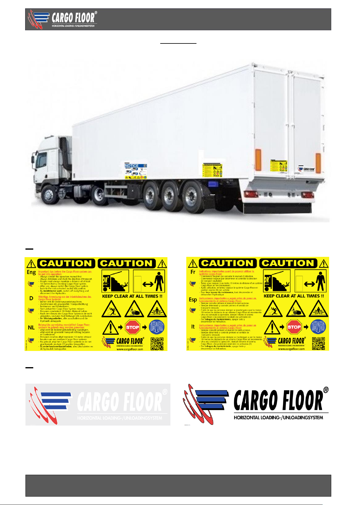
STICKERS
This WARNING STICKER/DECAL has been supplied with the drive unit in two fold. It should be attached
near the control box and on the rear door in such a way that it is easy to read.
STICKERS/DECALS ON THE TRAILER
A
…………………………………………………………………………………………………………………………
B
White/transparent Black/ transparent
or
………………………………………………………………………………………………………………………..
A + C
A B D
C
Page 7
Technical user manual SLC General
www.cargofloor.com
www.cargofloor.com Page 7
Version 01 / July 10th, 2017
C
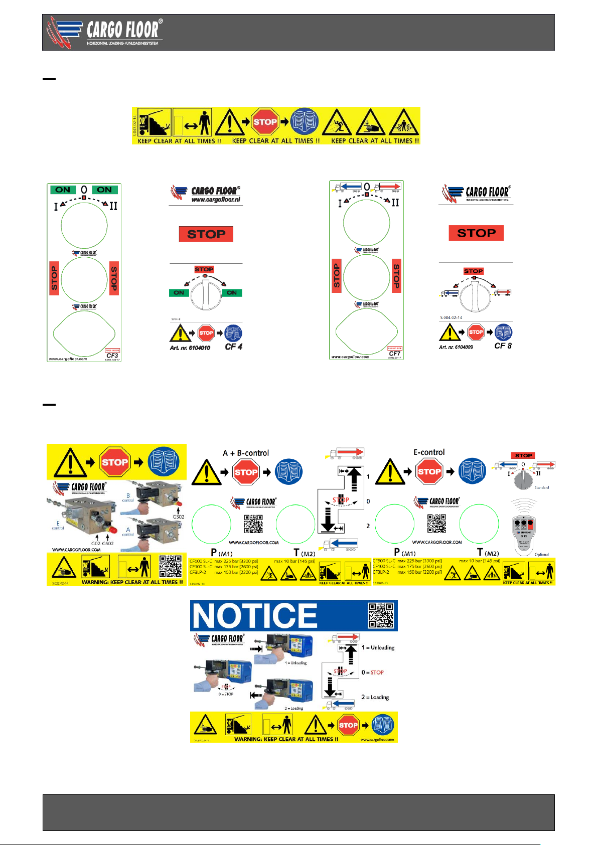
STICKERS/DECALS ON THE CONTROL BOX, ONLY WITH B- AND E-CONTROL
STICKERS/DECALS ON THE SWITCHES
Switch B-control Switch B-control Switch E-control Switch E-control
…………………………………………………………………………………………………………………………
D
STICKERS/DECALS ON THE SIDE OF THE TRAILER, NEAR THE DRIVE UNIT
Only A + B-control
Page 8
Technical user manual SLC General
www.cargofloor.com
www.cargofloor.com Page 8
Version 01 / July 10th, 2017
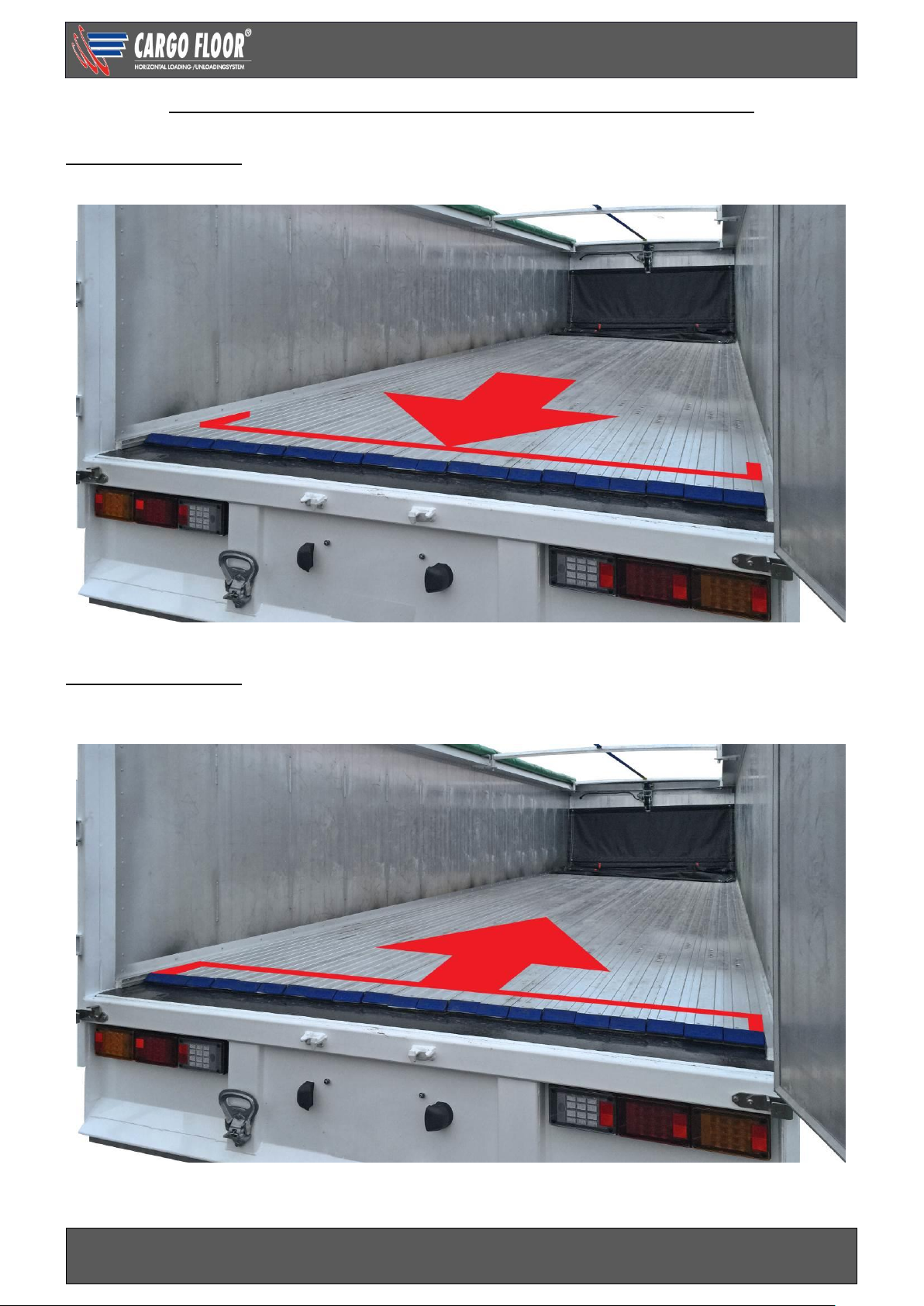
HOW TO CHECK THE CHOSEN LOADING/UNLOADING FUNCTION
UNLOADING
The complete surface of the floor moves simultaneously towards the open rear doors of the trailer.
The 3 individual movements go the opposite way (towards the front headboard of the trailer).
LOADING
The complete surface of the floor moves simultaneously towards the front headboard of the trailer
(direction of the truck).
The 3 individual movements go the opposite way (towards the open rear doors of the trailer).
Page 9
Technical user manual SLC General
www.cargofloor.com
www.cargofloor.com Page 9
Version 01 / July 10th, 2017
MODULAR OPERATING POSSIBILITIES
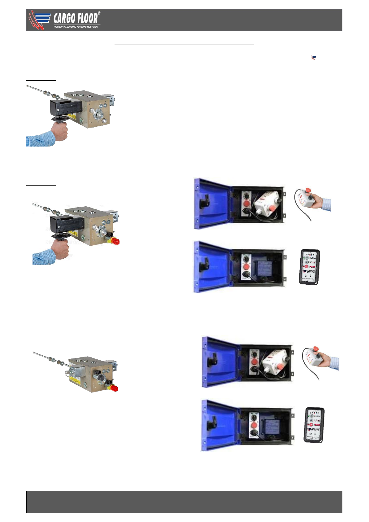
Thanks to its modular construction, the following operative versions of the Cargo Floor moving
floor® system are possible (also retrofittable):
A control
A-control with loading / stop / unloading over a manual handle, with unique "S" detent mechanism in
order to determine loading / stop / unloading position. (Non-electrical.)
B control
B-control with loading / stop / unloading over a manual handle, with unique "S" detent mechanism in
order to determine loading / stop / unloading position. on / off switching over a switch.
As a standard provided with a manual override by means of a unique red “Cargo” rotary switch.
(Optional: radio remote control.)
E control
E-control with loading / stop / unloading over a
switch
As a standard provided with a manual override by
means of a unique red “Cargo” rotary switch.
(Optional: radio remote control.)
Manual override by means
of a unique red “Cargo”
rotary switch.
OPTION
STANDARD
OPTION
STANDARD
Page 10

Technical user manual SLC General
www.cargofloor.com
www.cargofloor.com Page 10
Version 01 / July 10th, 2017
WET KIT INFORMATION
This wet kit is designed to be used with most transmissions. Power Take Off (P.T.O.) specifications may
vary with some transmissions. Please check with your supplier for specific applications.
The wet kit used to power the Cargo Floor system must comply with the following specifications:
CF500
SLC
CF100
SLC
CF500
SLC
Power
Speed
CF3 LP-2
CF600 HDC
CF800
Advised pump
capacity (l/min [gpm])
110 [29]
70 [18]
180 [48]
110 [29]
110 [29]
110 [29]
Max. Pump capacity
(l/min [gpm])
130 [34]
80 [21]
200 [53]
170 [45]
190 [50]
130 [34]
Max. Pressure relieve
valve *bar [psi]
250 [3,625]
200 [2,900]
250 [3,625]
175 [2,538]
220 [3,191]
250 [3,625]
*Pressure relieve valve must have the ability to relieve the full pump flow at the maximum pressure for
the system.
PRINCIPLE WET KIT DIAGRAM
Page 11
Technical user manual SLC General
www.cargofloor.com
www.cargofloor.com Page 11
Version 01 / July 10th, 2017
Oil: See “hydraulic recommendations”.
Pump: All gear pumps regardless of make or model should be "run in" as per manufacturer's
recommendations before connecting to the trailer for the first time.
Return filter: Filter should be 10 to 30 micron on the return line. Filter should be mounted as close to the
reservoir as possible. Return filter elements should be changed after 6 hours initially and every 6 months
thereafter.
Hydraulic Reservoir: Should hold approximately 1 liter [1 gallon] of oil for every liter [gallon] per minute
of pump output. (110 l/min [29 gpm] pump = minimum 110 liter [29 gal] reservoir)
Suction line: Hydraulic suction line with a 50 mm [2"] inside diameter, not more than 1500 mm [5'] long
Pressure line: All pressure lines should be minimum diameter of 20x2 mm [3/4”]
Return line: all hoses and lines should be a minimum diameter of 25x2 mm [1”]
Pressure relief valve: Must be pilot operated type, and sized correctly for the system. See wet kit
specification.
Hydraulic recommendations
1. Use ISO 22 grade oil if the minimum operating temperature is between -25 and 0 °C [-13 and 32
°F].
2. Use ISO 32 grade oil if the minimum operating temperature is between -15 and 30 °C [5 and 86 °F].
3. Use ISO
46
grade oil if the operating temperature range is between
15
and
40
°C [59 and 104 °F].
Note: The suggested maximum viscosity value for start-up is
1000
cSt.
Temperature below
-25 [-13
°F] degree Celsius
Use the following warm up procedure in temperatures below -25 degrees Celsius [-13°F]:
1.
Set the operation handle for unload (1) – 0 – load (2) in the middle 0-position
2. Circulate the oil for a few minutes to preheat it and lower its viscosity.
HYDRAULIC START-UP CHECK LIST FOR THE CARGO FLOOR SYSTEM
Before starting your new Cargo Floor (un)loader, a quick start-up check should be made
1. Hydraulic: is your entire system plumbed to the plumbing diagram?
2. *Pump: Will it pump the advised flow at the maximum pressure according to the system?
3. *Relief Valve: is it set at the maximum pressure according to the system?
4. Hydraulic reservoir: Is it big enough and filled?
5. Power Take Off: Is the P.T.O. engaged?
6. Hoses: Is the pressure line on the trailer attached to the pressure line on the tractor and the return
line on the trailer attached to the return line on the tractor?
7. Quick Disconnects: are these suitable and connected the right way?
8. Controls Cargo Floor: Operation handle unload (1) - 0 - load (2) in position 0?
*If the information about your pump and relief valve is not known, a pressure/flow check will help
determine this information. Be sure that your entire wet kit system meets the requirements of the
hydraulic wet kit specifications in this manual.
Less than -25 °C [-13°F]
-25
-
0 °C [-13 – 32 °F]
-15 - 30
°C [5 – 86 °F]
15 - 40
°C [59-104 °F]
Warm up
ISO 22
ISO 32
ISO 46
Page 12

Technical user manual SLC General
www.cargofloor.com
www.cargofloor.com Page 12
Version 01 / July 10th, 2017
IDENTIFICATION PLATE
Attention! With all communications we will ask for the system number. Fill out your system number here
to have it present at all times:............................
Underneath the trailer
At the side of the trailer
(near the pressure filter)
Page 13
Technical user manual SLC General
www.cargofloor.com
www.cargofloor.com Page 13
Version 01 / July 10th, 2017
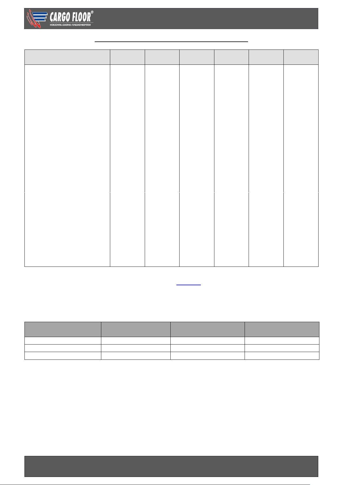
CARGO FLOOR TECHNICAL SPECIFICATIONS
CF500
SLC
CF100
SLL
CF500
Power speed
CF3 LP-2
(leak proof)
CF600
HDC
CF800
HD-6
Bore (mm [inch])
100 [3.9]
80 [3.15]
100 [4]
125 [4.9]
120 [4.7]
100 [3.9]
Piston rod diameter (mm [inch])
45 [1.77]
35 [1.38]
45 [1.77]
60 [2.35]
45 [1.8]
50 [2]
Stroke (mm [inch])
200 [8]
150 [5.9]
200 [8]
150 [5.9]
200 [8]
200 [8]
Cylinder volume ltr. [gallon]
2,82 [0.7]
1,36 [0.4]
2,82 [0.75]
3,26 [0.9]
4,2 [1.1]
5,5 [1.5]
Oil volume per cycle (ltr.
[gallon])
8,5 [2.2]
4,09 [1.1]
8,46 [2.25]
9,77 [2.6]
12,6 [3.3]
16,5 [4.4]
Pressure relief valve setting,
max. pressure (bar [psi])
225 [3,263]
175 [2,538]
225 [3,300]
150 [2,175]
205 [2973]
225 [3,300]
Strokes per minute with advised
pump capacity
13
17
21
11
8,7
6,6
Speed (mtr. / min [ft./min]) with
advised pump capacity
2,6 [8.5]
2,6 [8.5]
4,2 [13.8]
2,0 [6.6]
1,7 [5.6]
1,3 [10]
Advised pump capacity:
Flow (ltr./min [gpm]
110 [29]
70 [18.5]
180 [47.6]
130 [34]
110 [29]
110 [29]
Pressure (bar [psi])
250 [3,625]
200 [2,900]
250 [3,625]
175 [2,538]
220 [3,200]
250 [3,625]
Max. pump capacity:
Flow (ltr./min [gpm])
130 [34.5]
80 [21]
200 [52.8]
170 [45]
190 [50]
!E-Control
130 [34.5]
130 [34.5]
Pressure (bar [psi])
250 [3,625]
200 [2,900]
250 [3,625]
175 [2,538]
220 [3,200]
250 [3,625]
Speed at maximum
pump capacity
(mtr. / min. [ft./min])
3,1 [10]
2,9 [9.5]
4,7 [15.4]
2,6 [8.5]
3,0 [9.8]
!E-control
2 [6.2]
1,6 [5.2]
Solenoid/coil; 24V DC only E and B control (optional available 12 V DC)
Pressure filter type; high-pressure 10 micron (part no. 7372005)
ESTIMATED UNLOADING TABLE
Specifications for a Cargo Floor CF500 drive unit with 100 mm [3.9"] bore cylinders.
Engine
Pump output
speed*
Unloading time
13.6 mtr [45 ft] trailer
550 RPM/m [rpm]
60 l/m [15 g/min]
1.4 m/min [4.6 ft/min]
9-10 minutes
750 RPM/m [rpm]
80 l/m [21 g/min]
1.9 m/min [5.9 ft/min]
7-8 minutes
1000 RPM/m [rpm]
110 l/m [
29
g/min]
2.6 m/min [8.5 ft/min]
5-6 minutes
These only are approximate meters per minute and should strictly be used as a reference!
Page 14

Technical user manual SLC General
www.cargofloor.com
www.cargofloor.com Page 14
Version 01 / July 10th, 2017
MAINTENANCE INSTRUCTIONS
When works require turning on the floor you should take care of that the floor can be shut down
immediately at any time. Places where clamping/clasping of body parts is possible may not be
approached when the system is moving.
For more detailed explanation of the execution of the works we would like to refer you to our website:
https://www.cargofloor.com/en/site/en_garantieformulier.
Check for the end user / owner after receipt of the new Cargo Floor trailer
Check a couple of days after receipt of the new trailer and / or after 10 loads / unloads and after one
month the connection between the aluminium floor profiles and the Cargo Floor system. You do this by
placing your finger half on the screw and half on the floor profile when the floor is operating.
Important: if you feel a difference in movement between the screw and the floor profile it means the floor
profile is not fastened enough. The screw connection of the whole profile group this concerns needs to
be renewed with new screws in accordance to the fastenings guidelines mentioned in the assembly
instructions (see www.cargofloor.com, downloads). Also the countersunk hole needs to be cleaned
properly. Do not check the screw connections with the help of an Allen key and do not simply just tighten
the screws, the Loctite connection will be broken.
Specifications of the screws:
M12 x 30 countersunk screws with hexagon socket, class 10.9, galvanized. DIN 7991 (dacromet). The
torque is 100 – 140 Nm [72 – 105 lbf.ft.]
Regular checks and preventive maintenance
To ensure that your Cargo Floor system operates reliably and has a long life, it is important that you
regularly perform careful checks on the following aspects:
- Replace the filter element every year, or more often if needed
- Change the oil every 2 years, or more frequently if required;
- The level of oil in the tank. See for oil levels and the oil specifications the wet kit information
- Floor profiles: are they still fixed, replace screws if necessary!
- Check the guide blocks for the 3 piston rods for wear
- Check the coupling nuts and couplings of all hydraulic components, and adjust if necessary!
- Oil tank: by taking the lid off the tank, you can remove any remains (condensation, dirt etc.) from the
bottom.
- Return-/pressure filter: by removing the filter lid/chamber you can check the filter element, or after
about one year replace it.
- Check the seal between the two fixated floor profiles and the moving profiles. If a margin exists in-
between, then adjust the fixated floor profiles, in order for the sealing to be optimal and leakage via
the side walls is prevented.
This is all necessary to avoid internal wear (of the pump/cylinders etc., for example).
New filter parts are available at your system builder. For the right type we refer you to our “exploded
views” which you can find on our website: www.cargofloor.com, downloads.
We want to emphasize that the minimal costs of replacing dirty parts or oil do not match the costs and
discomfort that can arise.
Page 15

Technical user manual SLC General
www.cargofloor.com
www.cargofloor.com Page 15
Version 01 / July 10th, 2017
ADJUSTMENT OF THE THREADED ROD OF THE CONTROL VALVE
Front side trailer Rear side trailer
All Cargo Floor systems have the threaded rod set and are fully tested. You therefore do not need to
adjust the threaded rod, but in certain circumstances (f.e. certain repairs) it may be necessary to check
or adjust the setting of the threaded rod. If switching spontaneously doesn’t go normally anymore, then
please make a good assessment first why this has happened.
Attention:
The pump and electrical installation must always be switched-off when working on the system; in
addition, the hoses and/or pipelines between the pump and the Cargo Floor should also be
disconnected.
If not the risk of entrapment arises!!!
Necessary tools:
2x spanner 17;
High viscosity oil;
Copper grease;
Steel brush.
Check that the threaded rod (1) is fastened securely to the switching valve, with pressing and pulling the
stroke is exactly 12 mm. [0.5”].
If not, then screw the threaded rod (1) as far as possible into the plunger and secure this with the contra
nut (2) (spanner size 17). Loosen nuts (3 and 4, spanner size 17) and move these about 3 cm [1.25”] in
the direction of the rear of the trailer.
Now switch the pump on while you are at a safe distance. The system will start to move and stops
automatically at the point where the command lip (7) no longer operates the switching valve, because
the spring (8) is no longer pushed. Switch off the pump immediately.
Now push the threaded rod (1) in the direction of the rear of the trailer until the spacer ring (9) touches
the control valve.
Tighten nuts (3 and 4) so far in the direction of the front side of the trailer that the spring is fully pushed
in, and secure them by tightening them against one another. Repeat this procedure for the other side
(nuts 5 and 6) by doing everything in opposite directions.
N.B. It is worthwhile spreading some copper grease on the threaded rod (1).
Page 16

Technical user manual SLC General
www.cargofloor.com
www.cargofloor.com Page 16
Version 01 / July 10th, 2017
WARRANTY CONDITIONS
Warranty shall only be given with the prior consent of Cargo Floor B.V.! With warranty requests always
fill in and send a warranty request form to Cargo Floor B.V. beforehand. You can fill in a request for
warranty simply on our website: https://www.cargofloor.com/en/site/en_garantieformulier
The warranty conditions, as specified in the most recent “Metaalunie” conditions, filed with the registrar
of the District Court of Rotterdam, are applicable in unabbreviated form. On request available.
A short extract of these conditions follows:
A warranty period of 12 months (starting directly after installation) applies for all Cargo Floor system
materials supplied by us. In the case of malfunction and/or manufacturing faults we are only responsible
for the costless supply of replacement parts, if:
- The warranty period is for the first equipment owner only
- The Cargo Floor system is installed by your trailer builder according to our installation procedures
- Our maintenance and control procedures have been followed
- In the case of a malfunction, the system builder, or Cargo Floor have been informed
The following components are not covered by the warranty:
- Malfunction of equipment, or caused by equipment, which was not supplied by Cargo Floor B.V.
- Malfunction caused by the use of dirty oil, or oil of the wrong type
- Malfunction caused by overheated oil, T. max. 70 °C. [158 °F]
- Malfunction caused by overloading or injudicious use
- Malfunction caused by improper repair work, or repair work which is carried out by third parties
- Malfunction caused by corrosive materials
- Filter elements and components, which are subject to normal wear-and-tear and are not warranty
items
- Defects in electrical components due to incorrect connection and/or incorrect voltage levels
- Consequential damages
The warranty is void if:
- The system is used for purposes, which have not been recommended Cargo Floor B.V.
- The wet kit is not as recommend in the Cargo Floor manuals
- The Cargo Floor system is not installed properly
- Load in excess of legal limit are moved as defined in Cargo Floor manuals and operating instructions.
- The Cargo Floor system has not constructed correctly by your trailer builder, insofar as this has a
negative influence on the operation of the system.
Cargo Floor B.V. hereby warrants, only to the first owner of a new Cargo Floor unloader from the
factory or selling distributor, that the Cargo Floor hydraulic parts and hydraulic components
shall be warranted as free from defects in material and workmanship for a period of one year to
the first registered owner from the date of the sale.
This warranty does not cover normal wear and tear, maintenance, or heat damage. It is not to be
construed as a service contract.
Note: Prevention of excessive heat in the hydraulic system is the single most important factor for
long system life. Bad pumps, improper wet kits and hydraulic restrictions cause excessive heat and will
damage the hydraulic system. Heat damage will void the warranty.
Page 17

Technical user manual SLC General
www.cargofloor.com
www.cargofloor.com Page 17
Version 01 / July 10th, 2017
Definition of normal use and service:
Normal use and service means the loading and/or unloading of uniformly distributed, non-corrosive
material, properly restrained and secured, on properly maintained public roads, with gross vehicle
weights not in excess of factory rated capacity.
Sole and exclusive remedy:
If the product covered hereby fails to conform to the above stated warranty, Cargo Floor B.V. sole liability
under this warranty and the owner’s sole and exclusive remedy is limited to repair or replacement of the
defective part(s) at a facility authorized by your dealer or Cargo Floor B.V.. This is the owner’s sole and
exclusive remedy for all contract claims, and all tort claims including those based on the strict liability in
tort and negligence. Any defective part(s) must be shipped freight prepaid to your dealer who will contact
Cargo Floor B.V..
Except as expressly set forth above, Cargo Floor B.V. makes no warranties:
Express, implied or statutory, specifically: No warranties of fitness for a particular purpose or warranties
of merchantability are made. Further, Cargo Floor B.V. will not be liable for incidental damages or
consequential damages such as, but not limited to, loss of use of the product, damage to the product,
towing expenses, attorney’s fees and the liability you may have in respect to any other reason.
Tort disclaimer:
Cargo Floor B.V. shall not have any liability in tort with respect to the products, including any liability
based on strict liability in tort and negligence.
If this warranty violates law:
To the extent any provision of this warranty, contravenes the law of any jurisdiction, that provision shall
be inapplicable in such jurisdiction and the remainder of the warranty shall not be affected thereby.
Page 18

Technical user manual SLC A-control
www.cargofloor.com
www.cargofloor.com Page 18
Version 01 / July 10th, 2017
A-CONTROL
Control with loading / stop / unloading over a manual handle, with unique "S" detent mechanism in order
to determine loading/stop/unloading position. Non electrical.
CONTROL VALVE
Systems fitted with A-control do not include any electrical operation. The system will begin to move
depending on the position of the operation handle on the control valve. The handle should be positioned,
before and after using the Cargo Floor, in the position stop (0) if the handle is in the position 1 or 2 the
system immediately starts to move when the pump/ PTO is activated.
LOADING – UNLOADING FUNCTION
PRECHECK!
BE CAREFUL: when starting the pump/pto the floor could start moving immediately!
In certain configurations the functions can be different from the standard situation as described
below. It is therefore very important to always test your configuration first without a load.
After use always return the controls to the non-activated 0 position.
The position of the handle:
1 handle pushed in;
floor will unload
0 handle in the middle position;
floor stops
2 handle pulled out;
floor will load
Operating handle
Loading - Unloading
Pressure
relief valve
Threaded rod
Page 19
Technical user manual SLC A-control
www.cargofloor.com
www.cargofloor.com Page 19
Version 01 / July 10th, 2017
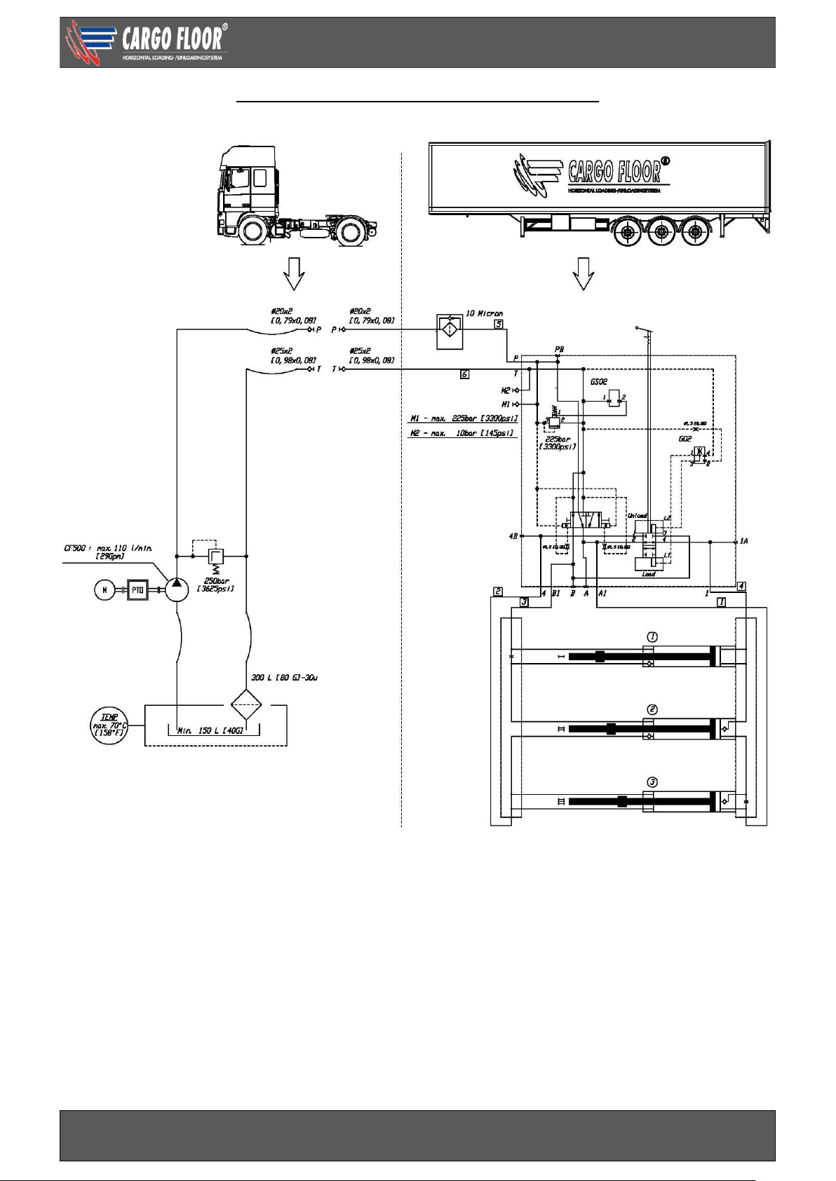
HYDRAULIC CIRCUIT DIAGRAM A-CONTROL
Page 20
Technical user manual SLC A-control
www.cargofloor.com
www.cargofloor.com Page 20
Version 01 / July 10th, 2017
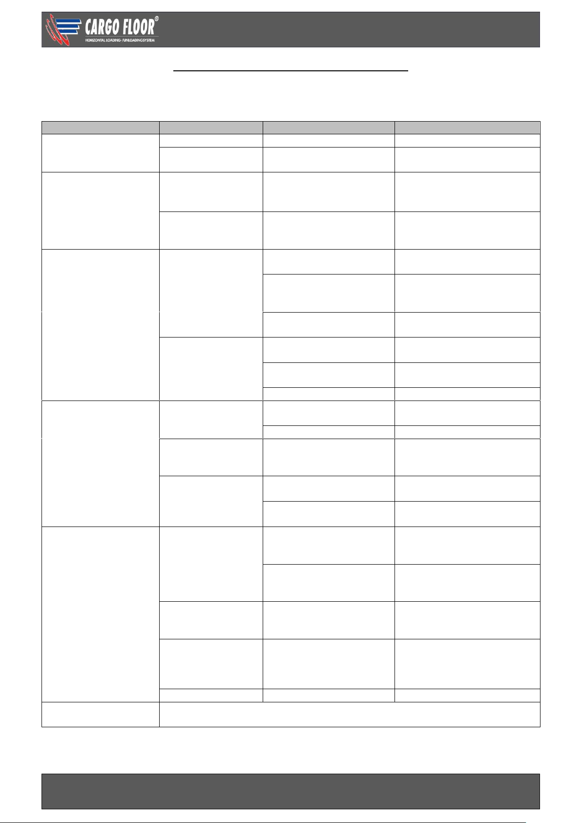
TROUBLESHOOTING A-CONTROL VALVE
In the event of the failure of the Cargo Floor system to operate (in the correct manner) when used in
accordance with the operating instructions carry out the following checks:
Malfunction system
Concerns part
Cause
Solution
1.Does not operate
No oil flow control
valve
PTO
Not switched on
Switch on PTO
Quick coupling
Blockade
Check couplings / mount
correctly
2. Does not operate
There is oil flow
control valve
Pressure control
valve
Polluted
Clean / replace, attention:
do not open the pressure
control valve in parts
Operating handle
Is in the middle position
Move the handle in the
direction of
loading/unloading
3. Individual
movement is
difficult and/or
incorrect with a full
trailer
Pressure control
valve
Tipper valve
Turn tipper valve in correct
position
Pressure control valve
pulling vehicle max.
pressure too low
Measure max. pressure/
adjust pulling vehicle
Return oil has
restrictions
Measure pressure M2,
remove restrictions
Capacity of the
system is
insufficient.
Too much load
Unload part of load with
crane
Pollution between the
Floor profiles
Clean
Frost
Thaw
4. Individual
movement is
incorrect when
unloading
With a full and empty
trailer
Valve in cylinder
head 1 or 2
Pollution prevents a
good connection
Remove pollution
Broken valve spring
Replace spring
Valve seat in
cylinder head 1 or
2
Valve seat has loosened
*Replace / fasten valve seat
Common rail
cylinder rod side
Stop in the common rail
has loosened
Fasten stop / replace
common rail
Common rail mounted
the wrong way around
Mount common rail
correctly
5. Switching is
difficult or goes not
at all. 3 Cylinders
are fully retracted or
fully out.
a. Threaded rod
Adjustment incorrect
Adjust correctly, attention:
determine cause. See: b.
and c.
Switching spring broken
Replace spring, attention:
determine cause. See: b.
and c.
b. Switching
plunger
Stroke > 12 mm. [0.5”] > threaded rod loose,
spacer loose
Screw in threaded rod / bolt
fully.
c. moving cross
member
Slanting caused by loose
profiles
*Replace screws and
provide them with a thread
locking product and check
the rod bearing.
d. Switching choke
Polluted
* Clean choke
6. Other
malfunctions
Please contact your trailer builder or Cargo Floor, keep the system number at
hand.
*Contact your trailer builder or Cargo Floor B.V. for a repair advise.
Page 21
Technical user manual SLC B-control
www.cargofloor.com
www.cargofloor.com Page 21
Version 01 / July 10th, 2017
B-CONTROL
Control with loading / stop / unloading with a manual handle, with unique "S" detent mechanism in order
to determine loading / stop / unloading position. On / off switching with a switch.
As a standard provided with a manual override by means of a unique red “Cargo” rotary switch.
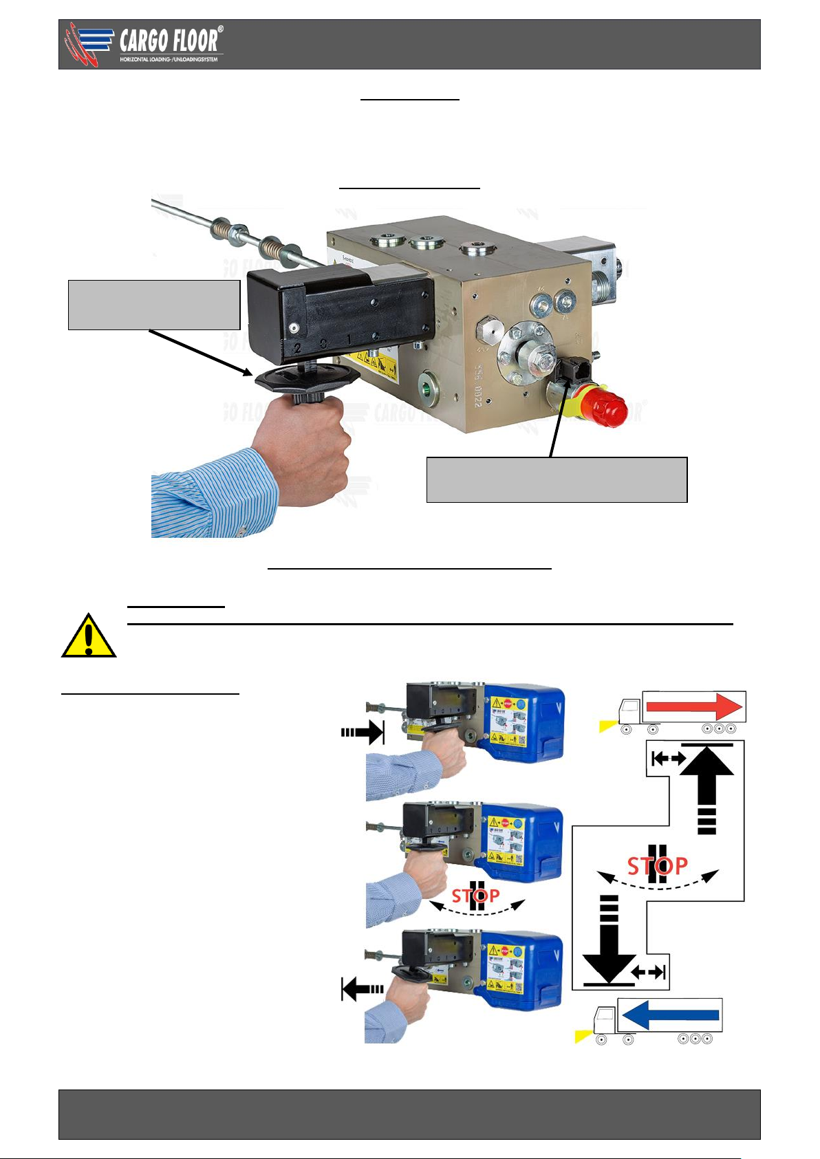
CONTROL VALVE
LOADING – UNLOADING FUNCTION
PRECHECK!
BE CAREFUL: when starting the pump/pto the floor could start moving immediately!
In certain configurations the functions can be different from the standard situation as described
below. It is therefore very important to always test your configuration first without a load.
After use always return the controls to the non-activated 0 position.
The position of the handle:
1 handle pushed in;
floor will unload
0 handle in the middle position;
floor stops
2 handle pulled out;
floor will load
Deutsch connector Black GS02
Function: On / Off
Operating handle
Loading - Unloading
Page 22
Technical user manual SLC B-control
www.cargofloor.com
www.cargofloor.com Page 22
Version 01 / July 10th, 2017
FUNCTION OF B-CONTROL SWITCHES
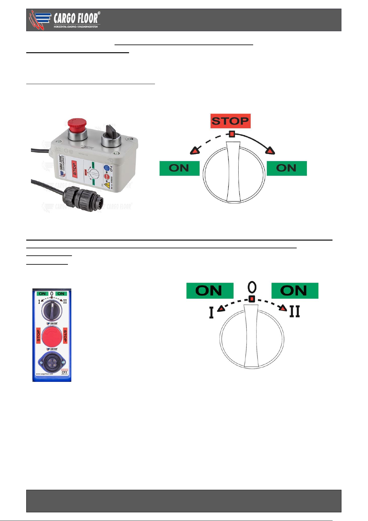
CF 4 SWITCH (MAIN CONTROL)
The standard supplied remote control CF4, with 10 meter [30’] of cable, is used for the day-to-day control
of the system. After you have manually put the handle in the loading / unloading function, the moving floor
system can turned on / off by using the electrical switch.
The CF4 switch has the following functions:
The CF4 switch has a plug connector, which can be inserted into the connector of the CF3 switch and
screwed tight.
TO DISCONNECT THIS, THE DUCT MUST BE UNSCREWED, AFTER WHICH THE PLUG CAN BE
PULLED OUT. NORMALLY, THIS PLUG SHOULD ALWAYS BE CONNECTED TO THE
CONNECTOR.
CF3 SWITCH
The CF3 switch is the permanent switch which is mounted in the control box and has 3 switch positions
with the following functions:
In the interest of safety this switch is fitted with an automatic spring-back for position I and II, so that it
always returns to “0” position. This is necessary to prevent conflict situations arising when using the CF4
remote control.
Mounted below the CF3 switch, is a connector to which the CF4 switch or the RX RECEIVER can be
connected without the need for any adjustments. Normally, the CF3 switch should only be used if the
CF4 switch is defective.
If, after the initial assembly, the switch does not work it is probably because the connections for the +
(brown) and the – (blue) have been swapped around. The supply cable contains a blocking diode which
prevents damages arising from the + and - from being connected in reverse.
A 2 Amp fuse has been mounted in the CF3 switch. Never mount a fuse over 3A, this can cause damage
to the electrical installation.
When turned left or right, it will start the floor and when
released it will automatically return to the 0 position
Red STOP button
Push in for an immediate STOP.
Deactivate by turning.
Turn right, it will start the
transport floor and when
released it stays
locked.
Rotary switch
Turn left, it will start the
transport floor and when
released it will
automatically return to the
stop position
Red STOP button
Push in for an
immediate STOP.
Deactivate by turning.
Page 23
Technical user manual SLC B-control
www.cargofloor.com
www.cargofloor.com Page 23
Version 01 / July 10th, 2017
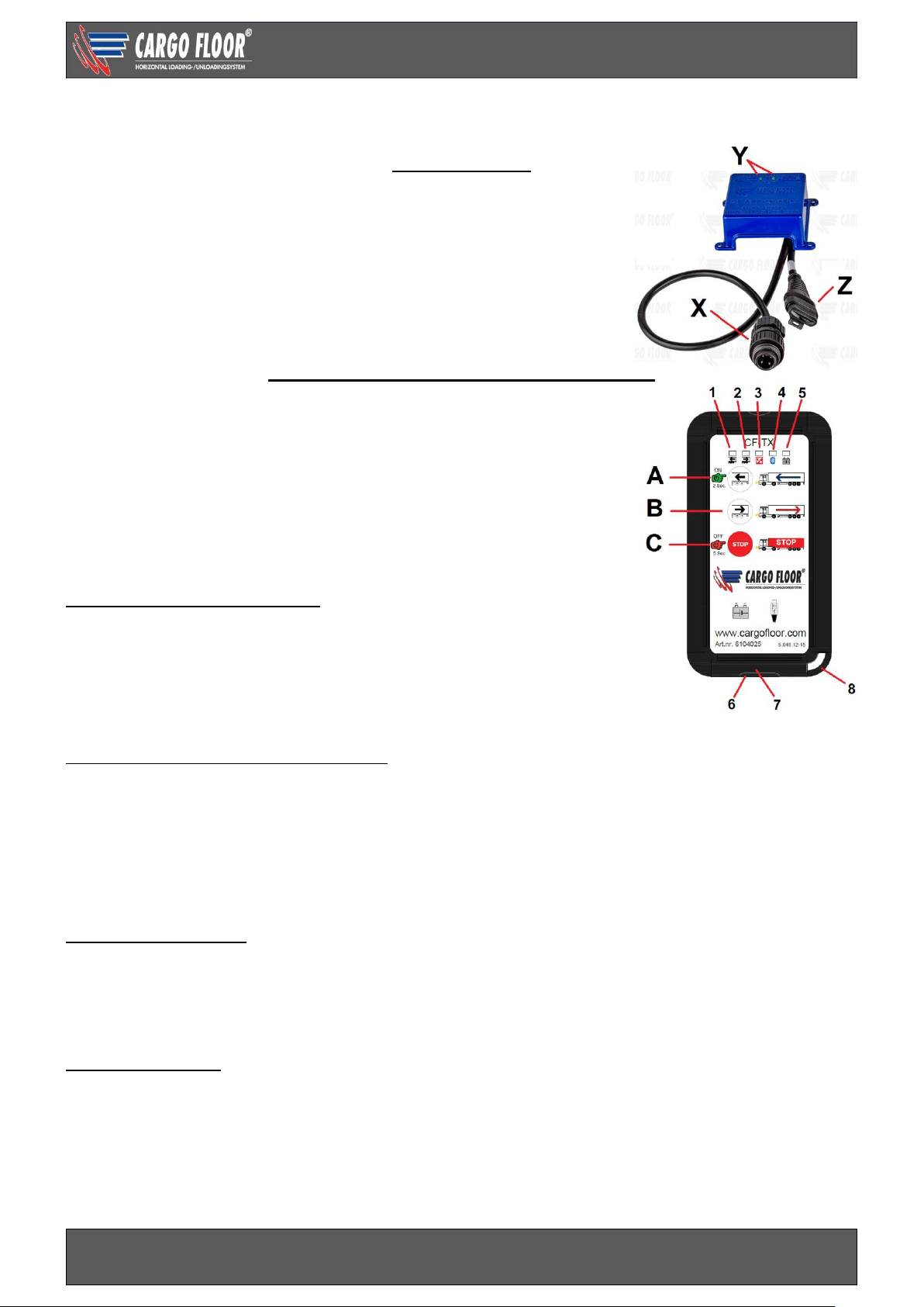
A radio controlled remote control is available as an option. (Bluetooth) registered.
This incorporates:
APP RECEIVER
The receiver has a connection cable with a 4P plug (X) for the
Cargo Floor moving floor system. This plug fits into the 4P socket
CF3 / CF7.
If the plug is plugged in or the power supply is turned on, this will be
indicated by both green led’s (Y) shortly lighting up. When operating
the transmitter and when switching on the function loading or
unloading the corresponding led will light up. The CAN bus (Z) plug
with blind lid should not be connected.
REMOTE CONTROL (CF TX) TRANSMITTER
The transmitter has been equipped with Bluetooth which has a very
stable wireless connection and a low battery (power) use. The
transmitter has a rechargeable battery that can be charged using
the micro-USB socket 6. When fully charged the stand by time will
be about 15-30 days. The transmitter has button lighting which will
automatically switch on when the light starts to fade (sensor 3).
When using the buttons, a bleep can be heard.
Do not put the transmitter in your pocket in order to avoid unwanted
operation of the system and battery drain.
Switching the transmitter on or off
Turn the transmitter on by pressing button A for 2 seconds. Led 1,
2, 4 and 5 will light up briefly. Led 4 will start to blink if there is a
connection between the remote control and the app receiver. The
transmitter will automatically switch off after 45 minutes. The
transmitter can be turned off by hand by pressing button C (stop) for
5 seconds.
Loading and unloading with the transmitter Button A (loading) By pressing this button, the system will turn on, led 1 will light up, by releasing it
the system will stop, led 1 will turn off.
Button B (unloading) By pressing this button, the system will turn on, led 2 will light up
By pressing it again the system will stop (or you press button C stop), led 1 will
turn off.
Button C (stop) This button stops the Cargo Floor system.
The transmitters battery
The transmitter has a chargeable Lithium’s polymers battery 750mAh.
LED 5 of the transmitter will give information on the battery status.
- Battery level is below 15%, the LED flashes 1x per second
- Battery level is below 10%, the LED flashes 2x per second
- Battery level is below 5%, the LED flashes 3 times per second
Charging the battery
Plug the USB-connector of the micro-USB cable into the 110/220V charger or into the USB car charger
12/24V.
Transmitter: open lid 7 and plug the micro-plug of the USB cable into socket 6. If the battery is charging
led 5 will be lit, it will switch off when the battery is fully charged. Unplug the micro connector. In order to
assure a good resistance against moist and prevent pollution, put back lid 7 into the transmitter after
charging.
Page 24
Technical user manual SLC B-control
www.cargofloor.com
www.cargofloor.com Page 24
Version 01 / July 10th, 2017
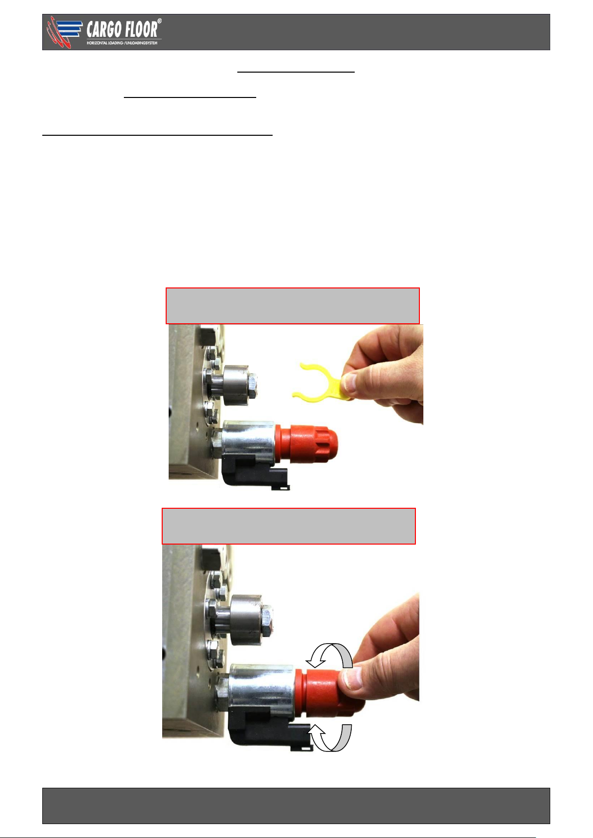
MANUAL OVERRIDE
In the event of a malfunction in the electrical system the electric valve can still be operated by activating
the manual override fitted for that purpose.
MAKE SURE THAT THE DOORS ARE OPEN!
When using this manual override you must always ensure that it is after use always deactivated
to the original non-activated position.
Activation of the manual override: ON
Remove the yellow security clip and turn in (clockwise) the red button on top of the on/off GS02 solenoid
till the stop. The system will switch “on” when the operation handle is in the load or unload position.
Deactivation of the emergency controls: ON
Turn out (counter clockwise) the red button on top of the GS02 solenoid until the click and place back the
yellow security clip. The system switches “off”.
On / off solenoid/coil
Not activated
On /off solenoid/coil
Manually activated
Deactivate
Activate
Page 25
Technical user manual SLC B-control
www.cargofloor.com
www.cargofloor.com Page 25
Version 01 / July 10th, 2017
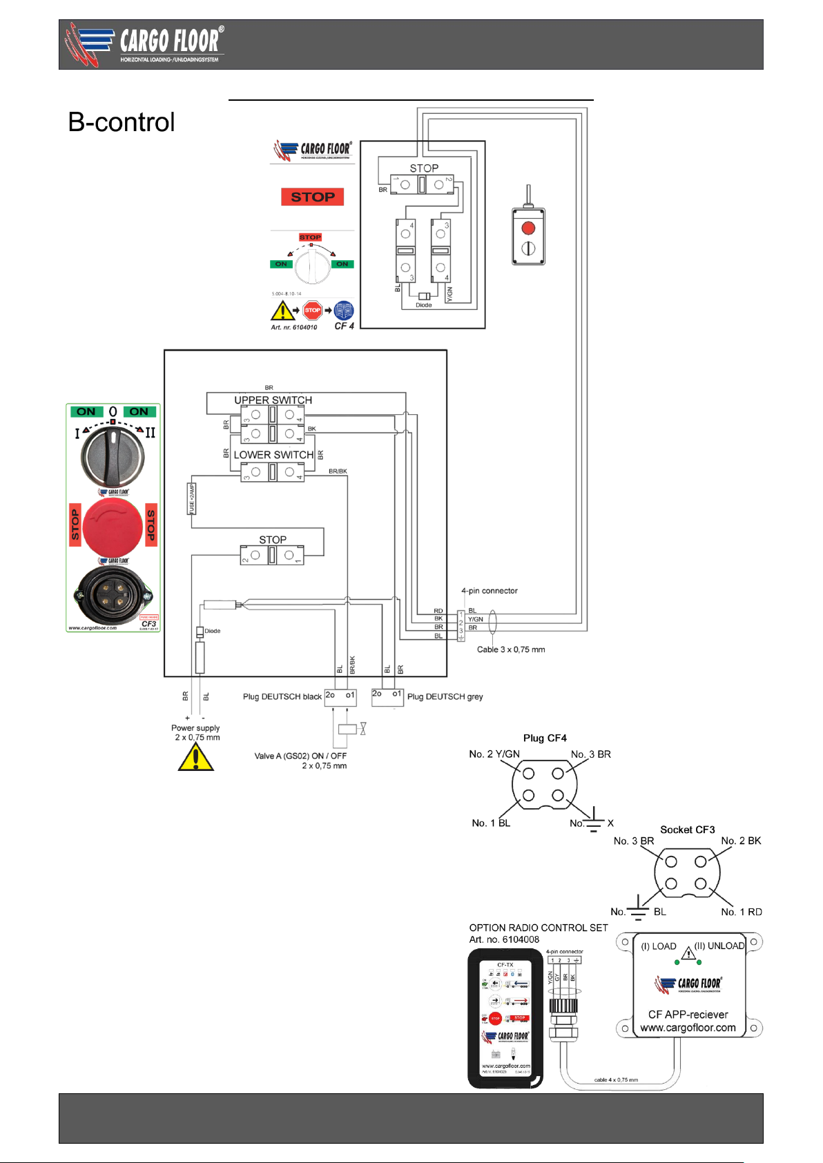
ELECTRICAL CIRCUIT DIAGRAM B-CONTROL
Page 26

Technical user manual SLC B-control
www.cargofloor.com
www.cargofloor.com Page 26
Version 01 / July 10th, 2017
HYDRAULIC CIRCUIT DIAGRAM
Page 27
Technical user manual SLC B-control
www.cargofloor.com
www.cargofloor.com Page 27
Version 01 / July 10th, 2017
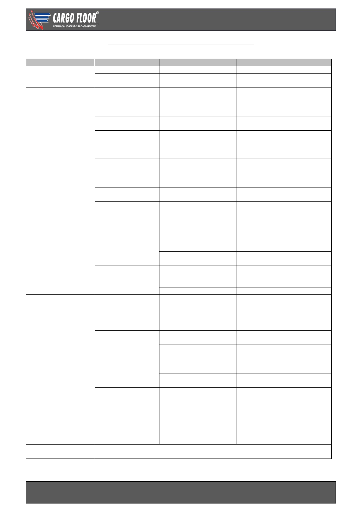
TROUBLESHOOTING B-CONTROL VALVE
In the event of the failure of the Cargo Floor system to operate (in the correct manner) when used in accordance
with the operating instructions carry out the following checks:
Malfunction system
Concerns part
Cause
Solution
1.Does not operate
No oil flow control
valve
PTO
Not switched on
Switch on PTO
Quick coupling
Blockade
Check couplings / mount
correctly
2. Does not operate
There is oil flow control
valve
Switch
Stop operated
De-activate stop
Solenoid valve GS02
on/off
Interruption wiring
Interruption in coil
Activate override GS02
temporarily and/or repair power
supply
Oil temperature
switch
Interruption solenoid due
to overheating
Let the oil cool down.
Pressure control
valve
Polluted
Clean / replace the pressure
control valve. Attention: do not
open the pressure control valve
in parts
Operating handle
Is in the middle position
Move the handle in the direction
of loading/unloading
3.Starts immediately
after switching on the
PTO
Switch CF3
Switch movement blocked
in the on position
Remove blockade
GS02 on/of
Manual override activated
De-activate manual override, put
yellow security clip back in place
Hoses connected
reversed
Pressure and return
hoses where swapped
Check filter first, then connect
pressure and return correctly.
4. Individual
movement is difficult
and/or incorrect with
a full trailer
Pressure control
valve
Tipper valve
Turn tipper valve in correct
position
Pressure control valve
pulling vehicle max.
pressure too low
Measure max. pressure/ adjust
pulling vehicle
Return oil has restrictions
Measure pressure M2, remove
restrictions
Capacity of the
system is insufficient.
Too much load
Unload part of load with crane
Pollution between the
floor profiles
Clean
Frost
Thaw
5. Individual
movement is
incorrect when
unloading
With a full and empty
trailer
Valve in cylinder
head 1 or 2
Pollution prevents a good
closure
Remove pollution
Broken valve spring
Replace spring
Valve seat in
cylinder head 1 or 2
Valve seat has loosened
*Replace / fasten valve seat
Common rail cylinder
rod side
Stop in the common rail
has loosened
Fasten stop / replace common
rail
Common rail mounted the
wrong way around
Mount common rail correctly
6. Switching is
difficult or goes not
at all. 3 Cylinders are
fully retracted or fully
out.
a. Threaded rod
Adjustment incorrect
Adjust correctly, attention:
determine cause. See: b. and c.
Switching spring broken
Replace spring, attention:
determine cause. See: b. and c..
b. Switching plunger
Stroke > 12 mm. [0.5”] ->
threaded rod loose,
spacer loose
Screw in threaded rod / bolt
fully.
c. moving cross
member
Slanting caused by loose
profiles
*Replace screws and provide
them with a thread locking
product and check the rod
bearing.
d. Switching choke
Polluted
* Clean choke
7. Other
malfunctions
Please contact your trailer builder or Cargo Floor, keep the system number at hand.
*Contact your trailer builder or Cargo Floor for a repair advise.
Page 28

Technical user manual SLC E-control
www.cargofloor.com
www.cargofloor.com Page 28
Version 01 / July 10th, 2017
E-CONTROL
Control with loading / stop / unloading over a switch. As a standard provided with a manual override by
means of a unique red “Cargo” rotary switch.
CONTROL VALVE
FUNCTION OF E-CONTROL SWITCHES
PRECHECK!
BE CAREFUL: when starting the pump/pto the floor could start moving immediately!
In certain configurations the functions can be different from the standard situation as described
below. It is therefore very important to always test your configuration first wi thout a load.
After use always return the controls to the non-activated 0 position.
Threaded rod
Deutsch connector
Grey G02
Function: unloading / loading
Deutsch connector
black GS02
Function: on / off
Page 29
Technical user manual SLC E-control
www.cargofloor.com
www.cargofloor.com Page 29
Version 01 / July 10th, 2017
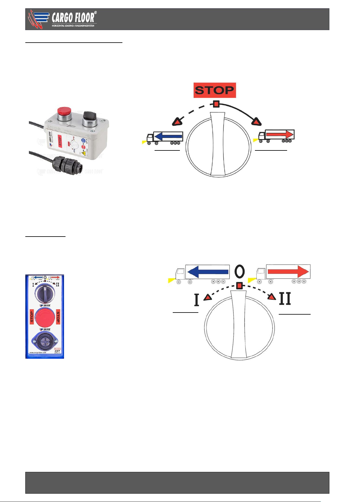
CF8 SWITCH (MAIN CONTROL)
The standard supplied remote control CF8, with 10 meter [30’] of cable, is used for the day-to-day control
of the system. The CF8 switch is fitted with the following functions:
The CF8 switch has a plug connector, which can be inserted into the connector of the CF7 switch and
screwed tight.
To disconnect this, the duct must be unscrewed, after which the plug can be pulled out. Normally, this
plug should always be connected to the connector.
CF7 SWITCH
The CF7 switch is the permanent switch which is mounted in the control box and has 3 switch positions
with the following functions:
In the interest of safety this switch is fitted with an automatic spring-back for positions I and II, so that it
always returns to the central “0” position. This is necessary to prevent conflict situations arising when
using the CF8 remote control. Mounted below the CF7 switch, is a connector to which the CF8 switch or
the RX RECEIVER can be connected without the need for any adjustments. Normally, the CF7 switch
should only be used if the CF8 switch is defective. If, after the initial assembly, the switch does not work
it is probably because the connections for the + (brown) and the – (blue) have been swapped around.
The supply cable contains a blocking diode which prevents damages arising from the + and - from being
connected in reverse.
A 2 Amp fuse has been mounted in the CF7 switch. Never mount a fuse over 3A, this can cause damage
to the electrical installation
When turned left or right, it will start the floor and when
released it will automatically return to the 0 position
Red button
Push in for an immediate STOP.
Deactivate by turning.
Loading
Unloading
Unloading
Turn right, it will start the
floor and when released
it stays locked.
Rotary switch
Red button
Push in for an
immediate STOP.
Deactivate by turning.
Loading
Turn left, it will start the
floor and when released
it will automatically
return to the stop position
Page 30
Technical user manual SLC E-control
www.cargofloor.com
www.cargofloor.com Page 30
Version 01 / July 10th, 2017
A radio controlled remote control is available as an option. (Bluetooth) registered.
This incorporates:
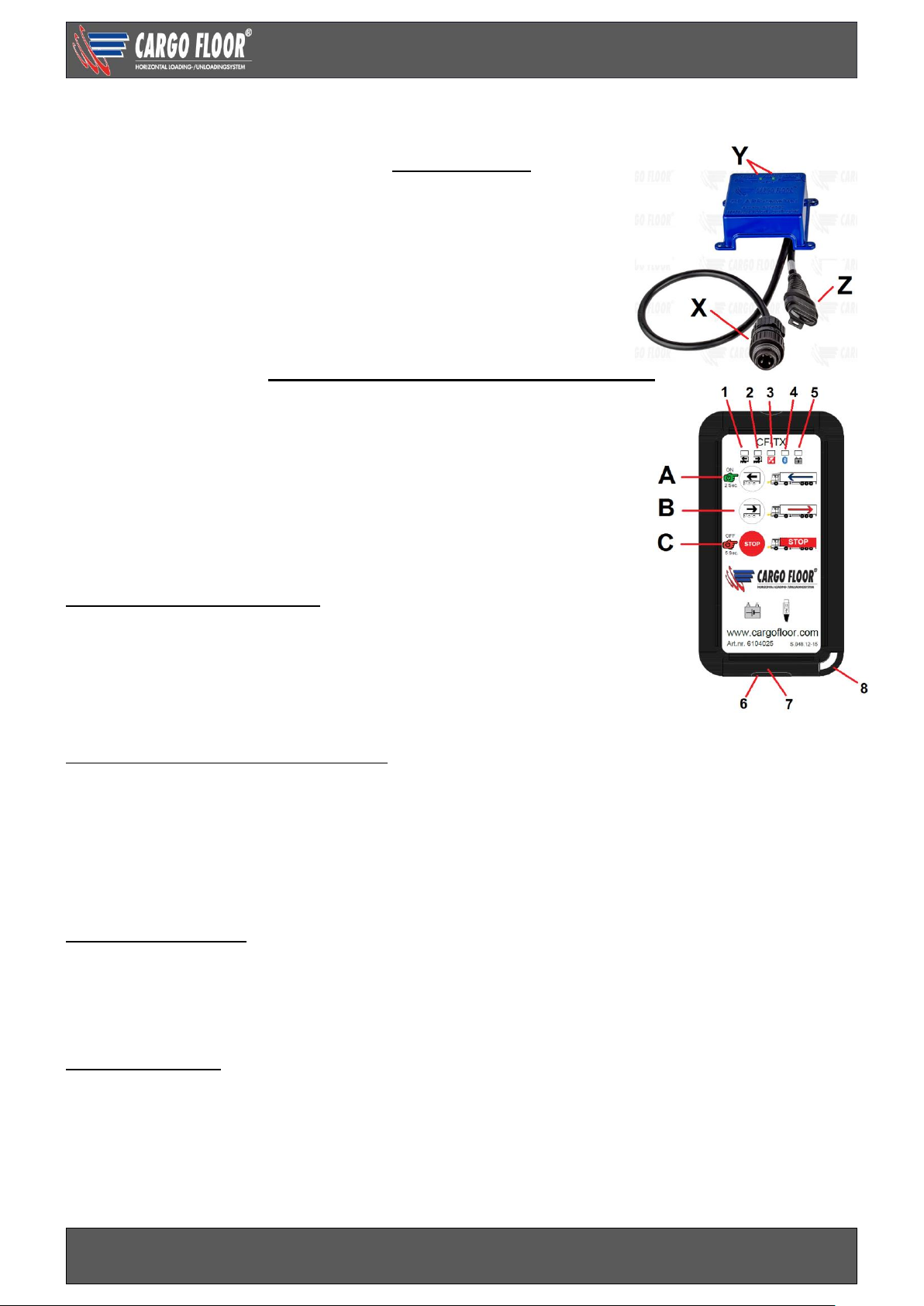
APP RECEIVER
The receiver has a connection cable with a 4P plug (X) for the
Cargo Floor moving floor system. This plug fits into the 4P socket
CF3 / CF7.
If the plug is plugged in or the power supply is turned on, this will be
indicated by both green led’s (Y) shortly lighting up. When operating
the transmitter and when switching on the function loading or
unloading the corresponding led will light up. The CAN bus (Z) plug
with blind lid should not be connected.
REMOTE CONTROL (CF TX) TRANSMITTER
The transmitter has been equipped with Bluetooth which has a very
stable wireless connection and a low battery (power) use. The
transmitter has a rechargeable battery that can be charged using
the micro-USB socket 6. When fully charged the stand by time will
be about 15-30 days. The transmitter has button lighting which will
automatically switch on when the light starts to fade (sensor 3).
When using the buttons, a bleep can be heard.
Do not put the transmitter in your pocket in order to avoid unwanted
operation of the system and battery drain.
Switching the transmitter on or off
Turn the transmitter on by pressing button A for 2 seconds. Led 1,
2, 4 and 5 will light up briefly. Led 4 will start to blink if there is a
connection between the remote control and the app receiver. The
transmitter will automatically switch off after 45 minutes. The
transmitter can be turned off by hand by pressing button C (stop) for
5 seconds.
Loading and unloading with the transmitter Button A (loading) By pressing this button, the system will turn on, led 1 will light up, by releasing it
the system will stop, led 1 will turn off.
Button B (unloading) By pressing this button, the system will turn on, led 2 will light up
By pressing it again the system will stop (or you press button C stop), led 1 will
turn off.
Button C (stop) This button stops the Cargo Floor system.
The transmitters battery
The transmitter has a chargeable Lithium’s polymers battery 750mAh.
LED 5 of the transmitter will give information on the battery status.
- Battery level is below 15%, the LED flashes 1x per second
- Battery level is below 10%, the LED flashes 2x per second
- Battery level is below 5%, the LED flashes 3 times per second
Charging the battery
Plug the USB-connector of the micro-USB cable into the 110/220V charger or into the USB car charger
12/24V.
Transmitter: open lid 7 and plug the micro-plug of the USB cable into socket 6. If the battery is charging
led 5 will be lit, it will switch off when the battery is fully charged. Unplug the micro connector. In order to
assure a good resistance against moist and prevent pollution, put back lid 7 into the transmitter after
charging.
Page 31
Technical user manual SLC E-control
www.cargofloor.com
www.cargofloor.com Page 31
Version 01 / July 10th, 2017
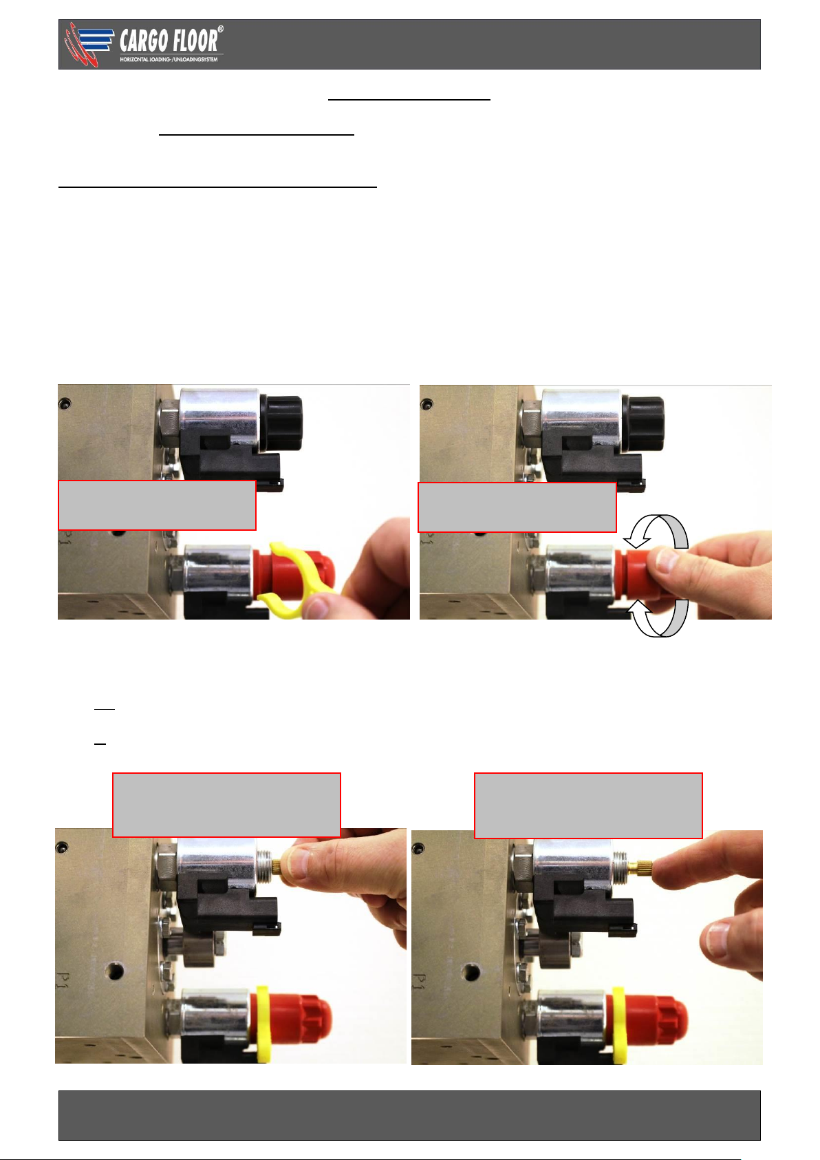
MANUAL OVERRIDE
In the event of a malfunction in the electrical system the electric valve can still be operated by activating
the manual control fitted for that purpose.
MAKE SURE THAT THE DOORS ARE OPEN!
When using this manual override you must always ensure that it switched back to the original,
NON-ACTIVATED condition after use.
Activation of the manual override: ON
Remove the yellow security clip and turn in (clockwise) the red button on top of the on/off GS02 solenoid
till the stop.
Deactivation of the manual override: ON
Turn out (counter clockwise) the red button on top of the GS02 solenoid until the click and place back the
yellow security clip. The system switch “off”.
Activation of the manual override control loading (floor will only be able to load):
Screw the black cap off (pay attention to the O ring).
Turn out (counter clockwise) the screw under the cap of the load / unload G02 till the stop.
Deactivation of the manual override loading:
Turn in (clockwise) the screw under the cap of the load / unload G02 till the stop.
Screw the black cap back on (pay attention to mounting the O ring).
Load/unload solenoid/coil
Not activated
Function: Unloading
Load/unload solenoid/coil
Activated
Function: Loading
On /off solenoid/coil
Manually activated
On / off solenoid/coil
Not activated
Deactivate
Activate
Page 32

Technical user manual SLC E-control
www.cargofloor.com
www.cargofloor.com Page 32
Version 01 / July 10th, 2017
ELECTRICAL CIRCUIT DIAGRAM E-CONTROL
Page 33
Technical user manual SLC E-control
www.cargofloor.com
www.cargofloor.com Page 33
Version 01 / July 10th, 2017
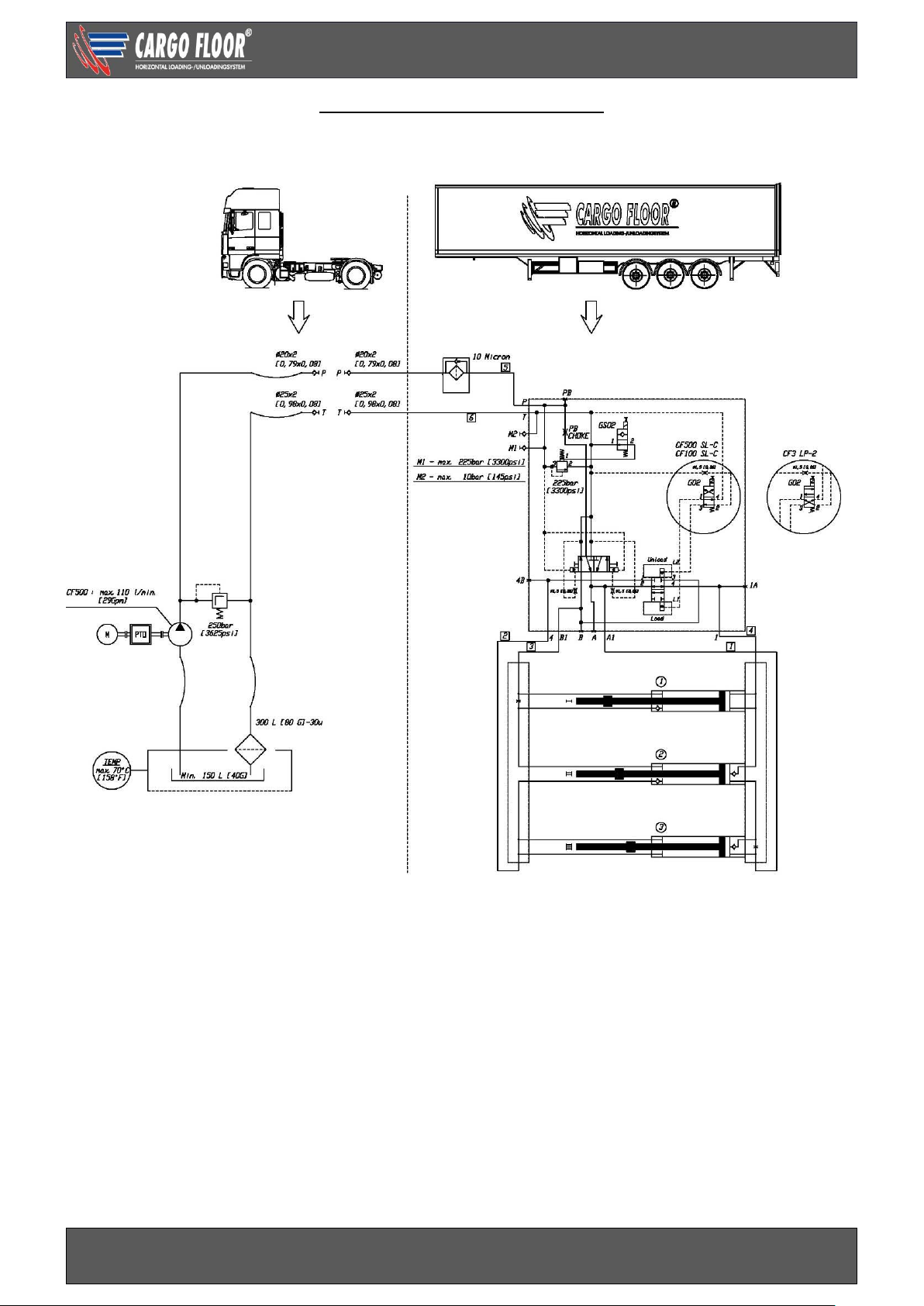
HYDRAULIC CIRCUIT DIAGRAM
Page 34
Technical user manual SLC E-control
www.cargofloor.com
www.cargofloor.com Page 34
Version 01 / July 10th, 2017
CHOKE
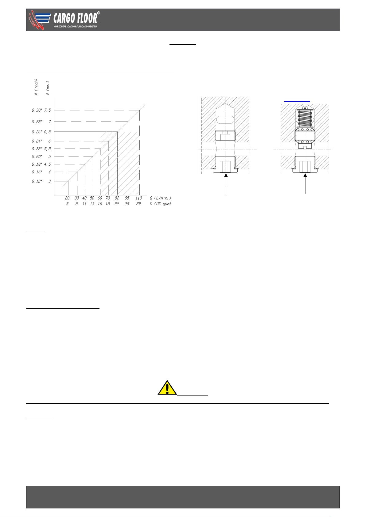
If the E-controlled Cargo Floor system will be operated by different types of pumps or a pump with a low
oil flow, it could be that you have to pay attention to mount another type of choke.
Choke
There is a standard 6,5 mm [0.26”] choke mounted as standard in the PB channel of the E control valve.
This allows the E control valve to function correctly. This standard choke is suitable for an oil flow level of
60 to 110 litres per minute [16 to 29 gpm]. The function of the control valve can be affected by a
deviation from this oil flow level. The oil flow diagram shows which level of oil flow is required by which
opening. Adjustment of this is possible by simply changing the diameter of the choke.
Known consequences of a wrong choke diameter are:
- Oil flow too low: load/unload operational plunger is not switching, system gets pressure less;
- Oil flow too high: noise in system, high heat dissipation and capacity loss.
Flow independent choke
As an option a flow independent choke can be supplied (variable choke article number 7370106). The
standard mounted choke can simply be changed with these. You remove the socket plug out of channel
PB (Allen key 12 mm). After this you screw the choke out of the channel with Allen key 12 mm. Screw
the new variable choke in the channel and fasten these by hand (about 15 Nm [11 lbf/ft.]). Screw the
socket plug back into channel PB (Allen key 12 mm) and fasten these by hand (about 15 Nm [11 lbf.ft]).
Let the floor run (loading and unloading) in order to check if everything is functioning well and no leakage
occur. The variable choke has a flow range of 20-120 ltr./min [5-31 gpm] ±10% using a VG32 and is
suitable for a maximal work pressure of 225 bar [3300 psi].
Important
Connecting pressure and return wrongly will cause a malfunction, and damage to, the system.
B-control
Another possibility to be independent from a variable oil flow is using a B-control. With this the
loading/unloading direction is determined by a handle.
PB
PB
Standard choke
DIN 906-5.8-3/4”
Variabele
choke Art. nr.
7370106
The shading points out the reach of the standard choke.
Page 35

Technical user manual SLC E-control
www.cargofloor.com
www.cargofloor.com Page 35
Version 01 / July 10th, 2017
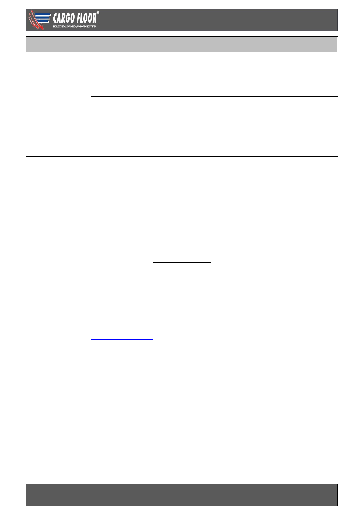
TROUBLESHOOTING E-CONTROL
In the event of the failure of the Cargo Floor system to operate (in the correct manner) when used in
accordance with the operating instructions carry out the following checks:
Malfunction
system
Concerns part
Cause
Solution
1.Does not operate
No oil flow control
valve
PTO
Not switched on
Switch on PTO
Quick coupling
Blockade
Check couplings / mount
correctly
2. Does not
operate
There is oil flow
control valve
Switch
Stop operated
De-activate stop
Solenoid valve
GS02 on/off
Interruption wiring
Interruption in coil
Activate manual override
GS02 temporarily and/or
repair power supply
Pressure control
valve
Polluted
Clean / replace pressure
control valve, attention: do
not open the pressure
control valve in parts
Oil temperature
switch
Interruption solenoid due to
overheating
Let the oil cool down.
Operation plunger in
the middle position
Flow <60 l/m [16 US gpm]
See chapter: choke
Increase pump rpm
Install another pump
Adjust choke
Hoses connected reversed
Check filter first, then
connect pressure and return
correctly.
Plunger moves with difficulty
due to molten seal
Replace seals operation
plunger
3.Starts
immediately after
switching on the
PTO
Switch CF7
Switch movement blocked in
the on position
Remove blockade
GS02 on/of
Manual override activated
De-activate manual override,
put yellow security clip back
in place
Hoses connected
reversed
Pressure and return hoses
are swapped
Check filter first, then
connect pressure and return
correctly.
4. Individual
movement is
difficult and/or
incorrect with a
full trailer
Pressure control
valve
Tipper valve
Turn tipper valve in correct
position
Pressure control valve pulling
vehicle max. pressure to low
Measure max. pressure/
adjust pulling vehicle
Return oil has restrictions
Measure pressure M2,
remove restrictions
Capacity of the
system is
insufficient.
Too much load
Unload part of load with
crane
Pollution between the profiles
Clean
Frost
Thaw
5. Individual
movement is
incorrect when
unloading
With a full and
empty trailer
Valve in cylinder
head 1 or 2
Pollution prevents a good
closure
Remove pollution
Broken valve spring
Replace spring
Valve seat in
cylinder head 1 or 2
Valve seat has loosened
*Replace / fasten valve seat
Common rail
cylinder rod side
Stop in the common rail has
loosened
Fasten stop / replace
common rail
Common rail mounted the
wrong way around
Mount common rail correctly
Page 36
Technical user manual SLC E-control
www.cargofloor.com
www.cargofloor.com Page 36
Version 01 / July 10th, 2017
Malfunction
system
Concerns part
Cause
Solution
6. Switching is
difficult or goes
not at all. 3
Cylinders are fully
retracted or fully
out.
a. Threaded rod
Adjustment incorrect
Adjust correctly, attention:
determine cause. See: b. and
c.
Switching spring broken
Replace spring, attention:
determine cause. See: b. and
c..
b. Switching plunger
Stroke > 12 mm. [0.5 inch] > threaded rod loose, spacer
loose
Screw in Threaded rod / bolt
fully.
c. Moving cross
member
Slanting caused by loose
profiles
*Replace screws and provide
them with a thread locking
product and check the rod
bearing.
d. Switching choke
Polluted
* Clean choke
7. Floor unloads
when choosing
loading and
unloading
Solenoid valve G02
loading / unloading
Interruption wiring
Interruption in coil
Activate manual override
G02 temporarily and/or repair
power supply
8. Floor loads
when choosing
loading and
unloading
Solenoid valve G02
loading / unloading
Manual override G02 is
activated
De-activate emergency
control
9. Other
malfunctions
Please contact your trailer builder or Cargo Floor B.V., keep the system number at
hand.
* Contact us for the right repair advice.
CONTACT DATA
Postal and visiting address:
Cargo Floor B.V.
Byte 14
7741 MK Coevorden
The Netherlands
Order spare parts:
After Sales (technical questions and malfunctions)
E-mail address: [email protected]
DID number: +31 524 593 981 / +31 524 593 991
Coevorden, The Netherlands © 2017 Cargo Floor B.V.
No part of this publication may be reproduced, stored in a retrieval system, or transmitted, in any form or
by any means, electronic, photocopying, recording or otherwise, without the prior permission of
Cargo Floor B.V.
 Loading...