

Cardioline ELI 100 User manual
REF 9507-008-50 REV E1
ELI 100 Service Manual
CAUTION: Federal law restricts this device to sale by or on the order of a physician.


®
Copyright© 1996-2006
by Mortara Instrument, Inc.
7865 N. 86th Street
Milwaukee, Wisconsin 53224
This document contains confidential information that belongs to Mortara Instrument, Inc. No part of this document may be
transmitted, reproduced, used, or disclosed outside of the receiving organization without the express written consent of Mortara
Instrument, Inc. Mortara is a registered trademark of Mortara Instrument, Inc. ELI 100 is a trademark of Mortara Instrument,
Inc.


Table of Contents
1 General
Service Manual Purpose ......................................................................................................1-1
User Safety Information ........................................................................................................1-1
Periodic Safety Inspections .....................................................................................1-1
Proper Power Cord ..................................................................................................1-1
Proper Fuse .............................................................................................................1-1
Do Not Operate in Explosive Atmospheres .............................................................1-1
Use Only Safe Methods of Interconnection .............................................................1-1
Do Not Mount Product above Patient ......................................................................1-1
Recommended Accessories ....................................................................................1-1
Sterilizing this Product .............................................................................................1-2
Liquid Spills .............................................................................................................1-2
System Information Log ...........................................................................................1-2
Product Information .................................................................................................1-2
Equipment Symbols ..............................................................................................................1-2
Symbol Delineation ..................................................................................................1-2
2 Maintenance and Cleaning
Introduction (Maintenance and Cleaning) .............................................................................2-1
Recommended Cleaning Supplies .......................................................................................2-1
List of Repair Materials .........................................................................................................2-1
Cleaning and Inspection Techniques ...................................................................................2-2
Interior Cleaning ...................................................................................................................2-2
Magnetic Cleaning ................................................................................................................2-2
Printed Circuit Board Cleaning .............................................................................................2-2
Metallic and Plastic Parts Cleaning ......................................................................................2-3
Exterior Cleaning ..................................................................................................................2-3
Printhead Cleaning ...............................................................................................................2-3
Inspection of Writer Assembly Harness ...............................................................................2-3
Printhead Adjustment ...........................................................................................................2-3
Exterior Inspection ................................................................................................................2-4
Interior Visual Inspection ......................................................................................................2-4
Preventive Maintenance Schedule .......................................................................................2-4
Cover Assembly Removal / Installation ................................................................................2-5
Writer Removal / Installation .................................................................................................2-5
Printhead Removal / Installation ...........................................................................................2-5
Paper Drive Motor Removal / Installation .............................................................................2-6
Printed Circuit Board Assembly Removal / Installation ........................................................2-6
Keyboard Removal / Installation ...........................................................................................2-6
LCD Removal / Installation ...................................................................................................2-7
Batteries Removal / Installation ............................................................................................2-7
i

3 Technical Description
Introduction (Technical) ........................................................................................................3-1
Processor Module (MPM) .....................................................................................................3-1
Modem Module (MMM) ........................................................................................................3-1
Main System Board ..............................................................................................................3-2
RS-232 Level Serial Port / High Speed Serial Port .................................................3-2
Writer Interface ........................................................................................................3-2
Writer Motor Control.................................................................................................3-2
Printhead Signal and Power Interface .....................................................................3-3
Keyboard Interface ..................................................................................................3-3
LCD Interface ..........................................................................................................3-3
Patient Input .............................................................................................................3-4
Speaker Interface ....................................................................................................3-4
Power Management Circuit .....................................................................................3-4
Power Supply ........................................................................................................................3-5
AC Input Power .......................................................................................................3-5
Battery Connections ................................................................................................3-5
Battery Charger and Printhead Supply ....................................................................3-5
5V Logic Supply .......................................................................................................3-5
5V Back-up Supply ..................................................................................................3-6
12V Programming Supply ........................................................................................3-6
Block Diagram ......................................................................................................................3-7
Keyboard Matrix ....................................................................................................................3-8
Battery Charging ...................................................................................................................3-8
Interconnection Diagram ......................................................................................................3-9
Interconnection List ..............................................................................................................3-10
RS-232 / High-Speed Serial Data Port ....................................................................3-10
AC Power Input .......................................................................................................3-10
Battery Input ............................................................................................................3-10
Writer Motor .............................................................................................................3-10
Writer Control / Power .............................................................................................3-11
Patient Input .............................................................................................................3-11
LCD Display Interface ..............................................................................................3-12
Spare Slot ................................................................................................................3-12
MPM Board Slot ......................................................................................................3-12
Keyboard Interface ..................................................................................................3-12
Engineering Debugger Interface .............................................................................3-13
4 Final Assembly
Parts List #1 - Final Assembly ................................................................................................4-1
Modem Card Optional Assembly Procedure ..........................................................................4-3
Modem Options ......................................................................................................................4-4
Final Assembly Notes ............................................................................................................4-5
ii

5 Base Assembly
Parts List #2 - Base Assembly ..............................................................................................5-1
Base Assembly Notes ..........................................................................................................5-3
6 4” Writer Assembly
Parts List #3 - Writer .............................................................................................................6-1
Writer Assembly Notes..........................................................................................................6-3
7 Printed Circuit Boards
Introduction to Printed Circuit boards....................................................................................7-1
Motherboard Ref: 26025-002-50 .............................................................................7-2
Motherboard Board Assembly Notes ......................................................................7-5
Motherboard Schematic Sheet 1 .............................................................................7-6
Motherboard Schematic Sheet 2 .............................................................................7-7
Motherboard Schematic Sheet 3 .............................................................................7-8
Motherboard Schematic Sheet 4 .............................................................................7-9
Motherboard Schematic Sheet 5 .............................................................................7-10
Processing Module (MPM) Board Ref: 26025-005-50.............................................7-11
Processing Module Assembly Notes Ref: 26025-005-50.........................................7-12
Processing Module (MPM) Board Ref: 26025-005-51.............................................7-14
Processing Module Assembly Notes Ref: 26025-005-51.........................................7-15
8 Testing and Troubleshooting
Equipment Required .............................................................................................................8-1
Introduction to Testing and Troubleshooting ........................................................................8-1
Fault Isolation Table .............................................................................................................8-1
Fault Isolation Table continued .............................................................................................8-2
Diagnosis ..............................................................................................................................8-2
1.0 AC On - Blank LCD, No Pixels Illuminated ........................................................8-2
2.0 AC On - Bar Across Top of LCD or Faint Illumination of Pixels ........................8-3
3.0 DC On - "Battery Low" Message Appears on Display .......................................8-3
4.0 DC On - No Response When DC 'ON' Key is Pressed .....................................8-3
5.0 Writer Test - Printing too Light or Too Dark or Uneven .....................................8-3
6.0 Writer Test - Gaps in Printing, Missing Dots, or No Printing at All ....................8-4
7.0 Writer Test - No Motor Drive .............................................................................8-4
8.0 Modem Test - No Dial-Tone or Touch-Tone Audio ...........................................8-5
Performance Testing ............................................................................................................8-5
Introduction to Performance Testing .......................................................................8-5
Equipment Required ................................................................................................8-5
Test Equipment Set-Up ...........................................................................................8-6
Initial Set-Up ............................................................................................................8-6
Noise Test ...............................................................................................................8-7
ECG, Keyboard and Cable Test ..............................................................................8-8
Rhythm Test ............................................................................................................8-8
Lead Fail Test ..........................................................................................................8-9
Directory Test ..........................................................................................................8-9
Transmit/Receive Test .............................................................................................8-10
iii

Direct Receive .........................................................................................................8-10
Modem Transmission ..............................................................................................8-11
Modem Receive .......................................................................................................8-11
Writer Self Test ........................................................................................................8-12
Description of Leakage Tests ..................................................................................8-12
Leakage Tests .........................................................................................................8-12
Earth Leakage Current Measurement .....................................................................8-12
Chassis Leakage Current Measurement .................................................................8-14
Patient Leakage Current Measurement ..................................................................8-15
Line Voltage Applied to Patient Connection Leakage Current Measurement .........8-16
Ground Integrity Test ...............................................................................................8-16
Appendix
Traces ...................................................................................................................................A-1
Appendix
Introduction to Modem Module(s) (MMM) ............................................................................B-1
Modem Module (MMM) 2 MRAM PCB Ref: 26025-003-50...................................................B-2
Modem Module (MMM) 2 MRAM PCB Ref: 26025-003-50 Assembly Notes .......................B-3
Modem Module (MMM) 16 MRAM PCB Ref: 26025-003-51.................................................B-6
Modem Module (MMM) 16 MRAM PCB Ref: 26025-003-51 Modification Notes..................B-7
Appendix
Introduction to Mortara Receiver Module(s) (MRM) .............................................................C-1
Mortara Receiver Module (MRM-915) PCB Ref: 26125-001-50...........................................C-1
Mortara Receiver Module (MRM-915) PCB Ref: 26125-001-50 Assembly Notes................C-2
Mortara Receiver Module (MRM-2500) PCB Ref: 26125-002-50.........................................C-4
Mortara Receiver Module (MRM-2500) PCB Ref: 26125-002-50 Modification Notes ..........C-6
A Testing and Troubleshooting
B Modem Module(s) (MMM)
C Mortara Receiver Module(s) (MRM)
Index.............................................................................................................................................I-1
Figures
Table 1 - Preventative Maintenance Schedule ...........................................................................2-4
Block Diagram - AC Power .........................................................................................................3-7
Keyboard Matrix ..........................................................................................................................3-8
Interconnection Diagram 1 ..........................................................................................................3-9
4-a Completed Final Assembly ...................................................................................................4-2
4-b Assembling Modem Card ......................................................................................................4-3
4-c Modem Installation ................................................................................................................4-4
4-d Label Placement on Writer ...................................................................................................4-5
4-e Serial Number and Part Number Label Placement on Bottom of Unit .................................4-6
4-f Label Placement on Unit ........................................................................................................4-7
4-g Label Chart ...........................................................................................................................4-7
4-h Ground Label Placement on Unit ..........................................................................................4-8
4-i Cover on Base Installation .....................................................................................................4-9
4-j Writer Door Installation ...........................................................................................................4-10
4-k Writer Installation ..................................................................................................................4-11
4-l LCD and Keyboard Installation ..............................................................................................4-12
iv

4-m Tape Placement ...................................................................................................................4-13
5-a Complete Base Assembly .....................................................................................................5-2
5-b Installing Tie Downs ..............................................................................................................5-3
5-c Labeling and Assembly of Batteries ......................................................................................5-4
5-d Installing Printed Circuit Board .............................................................................................5-5
6-a Complete Writer Assembly ...................................................................................................6-2
6-b Addition of Date Code Label and Bench testing ...................................................................6-3
6-c Installing Printhead and Copper Braid Cable ........................................................................6-4
6-d Installing E-Rings to Cover ...................................................................................................6-5
6-e Installing Main Pivot Shaft ....................................................................................................6-6
6-f Installation of Spring Bar ........................................................................................................6-7
6-g Installing Slider Plate ...........................................................................................................6-8
6-h Installing Alignment Deflector Shaft ......................................................................................6-9
6-i Installing Floating Cover and Grounding Gaskets .................................................................6-10
6-j Detail of Spring .......................................................................................................................6-11
6-k Installing Latch and Springs ..................................................................................................6-12
6-l Installing Slide Shaft, Bearing and Spring .............................................................................6-13
6-m Lower Chassis Complete .....................................................................................................6-14
6-n Completion of Lower Chassis ...............................................................................................6-15
6-o View of Bottom of Paper Trough ...........................................................................................6-16
6-p Installation of 48 Tooth Gear ................................................................................................6-17
6-q Installation of Platen and Gears ............................................................................................6-18
6-r Installation of Motor and Sound Dampeners..........................................................................6-19
7-a Motherboard ..........................................................................................................................7-2
7-b Motherboard 'X-Y' Coordinates .............................................................................................7-3
7-c Installation Details .................................................................................................................7-4
7-d Modification Detail .................................................................................................................7-4
7-e Sheet 1 of Motherboard Schematics ....................................................................................7-6
7-f Sheet 2 of Motherboard Schematics .....................................................................................7-7
7-g Sheet 3 of Motherboard Schematics ....................................................................................7-8
7-h Sheet 4 of Motherboard Schematics ....................................................................................7-9
7-i Sheet 5 of Motherboard Schematics ......................................................................................7-10
7-j Processing Module (MPM) Printed Circuit Board Ref: 26025-005-50....................................7-11
7-k Processing Module Card (MPM) 'X' & 'Y' Coordinates Ref: 26025-005-50 and -51..............7-13
7-l Processing Module (MPM) Printed Circuit Board Ref: 26025-005-51....................................7-14
7-m Sheet 1 of 3 Schematics for MPM Printed Circuit Board Ref: 26025-005-50 and -51.........7-16
7-n Sheet 2 of 3 Schematics for MPM Printed Circuit Board Ref: 26025-005-50 and -51..........7-17
7-o Sheet 3 of 3 Schematics for MPM Printed Circuit Board Ref: 26025-005-50 and -51..........7-18
Table 2 - Default Parameters ......................................................................................................8-6
Table 3 - Lead Fail Test ..............................................................................................................8-9
8-a Measuring Device Forms ......................................................................................................8-13
8-b Chassis Leakage ..................................................................................................................8-14
8-c Patient Sink Current ..............................................................................................................8-15
8-d Patient Source Current ..........................................................................................................8-16
A-a Trace 1 - Noise / Drift Test ...................................................................................................A-1
A-b Trace 2 - 12-Lead Auto ECG ................................................................................................A-2
A-c Trace 3 - Rhythm Strips ........................................................................................................A-3
A-d Trace 4 - Directory ................................................................................................................A-4
A-e Trace 5 - Writer Self Test .....................................................................................................A-5
B-a Modem Module (MMM) 2 MRAM Printed Circuit Board Assembly Ref: 26025-003-50........B-2
B-b Views and Details for Mounting Crystal.................................................................................B-3
B-c Modem Module (MMM) 2 MRAM Board 'X' & 'Y' Coordinates Ref: 26025-003-50...............B-4
B-d Modem Module (MMM) 2 MRAM Schematic Ref: 26025-003-50.........................................B-5
B-e Modem Module (MMM) 16 MRAM Printed Circuit Board Assembly Ref: 26025-003-51......B-6
B-f Installation of C27 and D100..................................................................................................B-7
B-g Installation of R8 and C101...................................................................................................B-7
v

B-h Installation of R102................................................................................................................B-8
B-i Installation of R101.................................................................................................................B-8
B-j Installation of CR2 ..................................................................................................................B-9
B-k Modem Module (MMM) 16 MRAM Schematic Ref: 26025-003-51.......................................B-10
C-a Mortara Receiver Module (MRM-915) PCB Assembly Complete Ref: 26125-001-50..........C-1
C-b Shield Can Installation Holes................................................................................................C-2
C-c Installation of Shield Can.......................................................................................................C-2
C-d Installation of Connectors......................................................................................................C-3
C-e Mortara Receiver Module (MRM-2500) PCB Assembly Complete Ref: 26125-002-50........C-4
C-f Installation of Connectors.......................................................................................................C-5
C-g Installation of MDC-2500 Assembled Printed Circuit Board .................................................C-6
vi

___________________________________________________________________________ Section 1
1 General
Service Manual Purpose
The purpose of this manual is to supply information to service personnel so they can maintain the ELI 100 12-Lead
Electrocardiograph at the assembly and subassembly level. Although the manual includes parts lists, mechanical
assembly parts, and printed circuit board information, it is intended to function primarily as a guide to preventative
and corrective maintenance and electrical repairs considered field repairable.
User Safety Information
Periodic Safety Inspections
Follow the recommended maintenance schedule. Inspect the power cord and transmission cables
periodically for fraying or other damage and replace as needed. Broken or frayed wires may cause
interference or loss of signal. Pay particular attention to points where wires enter connectors.
Proper Power Cord
Use only the power cord specified for the equipment. This product requires a three-wire, (18 gauge, SJTgrade) power cord, which is supplied with a three-terminal, polarized plug (hospital grade) for connection
to the power source and protective ground. Use only a power outlet with a protective ground outlet. An
interruption of the grounding connection could cause an electrical shock hazard.
Proper Fuse
Use only the fuse specified for the equipment (identical in type, voltage and current ratin g). Substituting a
different fuse type could cause a fire hazard. Always make sure fuses have been installed before operating
the unit.
Do Not Operate in Explosive Atmospheres
Do not operate the ELI 100 in the presence of flammable gasses or anesthetics; this environment could
cause
an explosion. Refer to Operator's Manual Safety Information: Warning(s) and Caution(s).
Use Only Safe Methods of Interconnection
To prevent electrical shock from the product when it is connected to other electrical equipment, proper
grounding is essential. Refer to Operator's Manual Safety Information: Warning(s) Peripheral equipment.
Do Not Mount Product above Patient
Do not mount or place the product where it could fall on a patient or where it could be accidentally knocked
off a shelf or other mounting arrangement.
Recommended Accessories
For the patient's safety and optimum equipment performance, use only the accessories specified by Mortara
Instrument, Inc.
1-1

ELI 100_____________________________________________________________________________
Sterilizing this Product
Do not sterilize this product or any accessories unless specifically directed by the manufacturer. Sterilization and
sterilization environments can seriously damage many components and accessories.
Liquid Spills
Do not set beverages or other liquids on or near the ELI 100, and/or optional equipment.
System Information Log
See Appendix "A" of Operator's Manual
Product Information
See Section 1 of Operator's Manual
Equipment Symbols
Symbol Delineation
Electrostatic sensitive devices
1-2
____________________________________________________________________________Section 2
Maintenance and Cleaning
2
CAUTION:
Remove battery fuse at right rear of unit before attempting any disassembly. Also,
removing the fuse at the right rear of the unit will cause the configuration parameters
to reset to the default setting. In addition, all ECGs stored in memory will be lost.
Introduction
This section provides servicing and maintenance instructions for the ELI 100 interpretive electrocardiograph.
Subsequent parts of this section are disassembly, inspection techniques, cleaning techniques, and installation.
Recommended Cleaning Supplies
Anti-static mat & wrist band, properly grounded
•
• Clean, lint-free cloth
• Cleaning solvent (isopropyl alcohol, 99% pure)
• DRY, low pressure, compressed air (30 psi)
• Electronic safe non-residue solvent, such as Flux-off
• Masking tape
• Non-metallic, soft-bristle brush
• Naphtha
• Vacuum cleaner, Static Safe
List of Repair Materials
Screwdriver Philips #2.
•
• Screwdriver, flatblade.
• Nutdriver set, standard.
• Multimeter.
• Oscilloscope.
Note: The equipment and solvent mentioned above are standard shop commodities that are available from
commercial sources. If in the performance of normal maintenance or repair, the PCB assembly, AC
connector assembly, AC switch assembly, or writer assembly are removed or replaced, a leakage test
should be performed. See section on testing.
2-1
ELI 100_____________________________________________________________________________
Cleaning and Inspecting Techniques:
This section contains instructions for periodic cleaning and inspection of the instrument as preventative maintenance
measures. It also contains specific cleaning procedures to be conducted after disassembly. Parts having identical
cleaning procedures are grouped under common headings. No special tools are required.
Interior Cleaning:
WARNING
Ventilate work area thoroughly when using solvents. Observe manufacturers warnings on
solvent containers with regard to personnel safety and emergency first aid. Be sure that first
aid equipment is available before using chemicals. Observe shop safety and fire
precautions. Ventilate all work areas where solvents are used. Store solvents and so lventsoaked rags in approved containers. Refer to manufacturers’ instructions on containers for
recommended fire-fighting procedures, and make sure that fire-fighting equipment is
available.
Magnetic Cleaning:
CAUTION
Clean transformers and inductors with a dry, non-metallic, soft bristle brush.
Do not use solvents to clean transformers or inductors. The chemical action of solvents may
remove the varnish from the wire coils, rendering the components useless. The solvent also
neutralizes the adhesive of the cover tape, resulting in eventual tape separation from the
windings.
Printed Circuit Board Cleaning.
Clean assembled parts with a vacuum cleaner or low pressure compressed air (60 psi). Take care when cleaning
printed circuit boards that wires or component leads are not bent back and forth in such a manner as to weaken them
and cause them to eventually break.
Prior to soldering, clean surfaces with a nonmetallic, soft bristle brush dipped in solvent.
Dry with low pressure compressed air.
2-2

____________________________________________________________________________Section 2
Metallic and Plastic Parts Cleaning
CAUTION
Brush all surfaces and parts with a nonmetallic, soft bristle brush.
Wipe metal surfaces with soft, nonabrasive cloth dampened with isopropyl.
Dry surfaces with clean cloth.
Wipe surfaces of nameplates and labels with dry cloth.
Do not wipe over surfaces of nameplates or labels with abrasive cleaners or materials, as
this will eventually wear away the nameplate information. Do not use solvents to clean
plastic parts.
Exterior Cleaning.
Use a damp cloth to clean external covers and the line cord. Do not use alcohol, solvents, or cleaning solutions.
These cleaning agents may damage the surfaces of the instrument.
Printhead Cleaning
Open the writer cover as explained in the section on final assembly.
Apply isopropyl alcohol to a clean cloth, and wipe the writer printhead until all foreign matter is removed.
After cleaning is completed, inspect the unit using the techniques described previously.
After the inspection is complete, install the cover as explained in the section on final assembly.
Inspection of Writer Assembly Harness
Visually inspect the wire harness for wear, maintenance damage, corrosion, deterioration, and damage resulting
from dropping.
If no defects are found, install the cover and restore the unit to service.
If a defect is found in the cable, replace it with a new cable.
Note: The removal of the writer assembly as explained later in this section, may be necessary to replace the
cable. After a cable is replaced, re-install the cover.
Printhead Adjustment
Refer to section on Testing and Troubleshooting.
2-3

ELI 100_____________________________________________________________________________
Exterior Inspection
Visually inspect the entire instrument for wear, maintenance damage, corrosion, deterioration, and damage resulting
from dropping.
Interior Visual Inspection
Check components, wiring, solder joints and printed circuit conductor patterns.
Check all connectors for loose, bent or corroded contact points
Check wire, harnesses and cables for signs of wear or deterioration.
Inspect sleeve and tubing for proper installation or evidence of damage.
Inspect components and their leads for security of mounting, deterioration or leakage.
Check terminals and connections for proper installation, failed soldering, loss or wear.
Inspect PCB surfaces for charring, cracking or brittle’s.
Note: Some degree of discoloration of the PCB surface may be expected due to continued exposure to the
operating temperatures of some of the components.
Check the identification nameplate and other decals for legibility.
Inspect chassis, covers, and brackets for warping, bending, surface damage or missing captive hardware.
Check all screws and nuts for tightness or signs of stripped or crossed threads.
Check for damage traces on PCBs. Look for lifted conductors and inspect for breaks, scratches, nicks, or pin holes.
Check for any other form of mechanical damage in which may indicate a failure.
If, during the process of normal maintenance or repair, the PCB assembly, AC connector assembly, AC switch
assembly, or writer assembly are removed and replaced, perform the leakage test as describe in the section on
Testing and Troubleshooting.
Preventative Maintenance Schedule:
Maintenance to be Performed Period Notes
Clean and inspect unit. 6 mo. Perform every 3 mo. if unit is in heavy use.
Printhead cleaning 80 hrs Perform every 40 hrs, if unit is being used with
ELI-XR.
Check printhead wire harness. 160 hrs Printhead adjustment - Adjust printhead when print head is replaced.
Leakage tests. - -
Table 1
2-4
____________________________________________________________________________Section 2
Cover Assembly Removal / Installation
Open the writer cover and remove the six flathead screws securing it. They are located at the front and on both sides
of the unit, near the bottom.
Lift the cover assembly gently and tilt it towards the right side of the unit as seen from the front. Set the co ver
assembly on its right side.
Unplug the paper drive motor cable (J6 of PCB), the power/data cable (J9 of PCB), the two keyboard cables (J4 of
PCB), and the LCD cable (J1 of PCB). Remove the writer mounting screw that holds the ground wire.
Note: Orientation for the J4 keyboard plug is as follows:
P12 is marked with 1 on one half of the flex tape. This half of P12 goes to J4 pin 9 of PCB.
The other half of the flex tape is marked with 9. This half plugs into J4 pin of the PCB.
J4 pin 9 is adjacent to pin 1.
Set the cover assembly aside with the top facing up. Reassemble on reverse order.
Writer Removal / Installation:
Remove the four Philips screws, which attach the cover assembly to the base of the unit. They are located at the
front and at both sides of the unit, near the bottom.
Unplug the printhead cable.
Remove the remaining writer mounting screws on the under side of the cover assembly.
Lift the writer from the tray and pull the paper drive motor cable through the slot at the rear of the tray. It may be
necessary to do some maneuvering with the connector. Reassemble in reverse order and see note under Printhead
Removal below.
Printhead Removal / Installation:
Remove the four printhead-mounting screws. If a tool is available for removing the E-rings, remove them from both
ends of the metal support bar and remove the bar in order to facilitate printhead removal.
Slide the printhead forward and gently press down on the printhead connector until it clears the lid assembly.
Remove the printhead. Reassemble in reverse order.
CAUTION
When installing a new printhead, make sure that the front edge of the printhead lines up
flush with the front of the lid before tightening the mounting screws. After the unit is
reassembled, run the writer self test as described under performance testing in the section
on Testing and Troubleshooting. It may be necessary to loosen the screws and skew the
printhead slightly at the top or bottom in order to get even printing across the entire trace.
2-5
ELI 100_____________________________________________________________________________
Paper Drive Motor Removal / Installation:
The writer must be removed from the unit first. Then, remove the screws, which hold the paper tray to the writer
chassis. Lift the paper tray part way.
Using a 1.3 mm Allen wrench, loosen the set screw on the motor gear and slide the gear off the shaft.
Remove the two mounting screws, which hold the motor to the chassis.
Remove the motor. Reassemble in reverse order.
Note: There are two different sets of threaded holes for the mounting screws. One is metric and one is English.
Try the mounting screws on the motor first before attempting to install the motor.
Printed Circuit Board Assembly Removal / Installation:
Disconnect all cables connecting the cover assembly (J1, J4, J6, and J9) to the circuit board and set the cover aside.
Unplug the battery cables from J10. Remove the two screws, which hold the battery tray to the base of the un it and
remove the battery pack.
Unplug the AC input assembly, (J8).
Remove the screw, which mounts the processor module to the base, and carefully remove the processor module
from its mating connection (J5). Remove the seven screws, which mount the board. Reassemble in the reverse
order.
CAUTION
When installing a new board, remove the battery fuse from F1 first. When all cables and the
batteries have been connected to the board, install the fuse.
Keyboard Removal / Installation:
Remove the cover, as explained previously.
Unplug the keyboard from J4 of the circuit. Note the position of the connectors.
Check the underside of the cover for four or five keyboard mounting nuts.
Use a 5.5mm nut driver to remove the nuts from the threaded studs in the keyboard.
Remove the two connectors through the slot in the cover assembly.
Removed any large deposits of glue from the cover assembly. If needed.
2-6
____________________________________________________________________________Section 2
CAUTION
Orientation for the J4 keyboard plug is as follows:
P12 is marked with a 1 on one half of the flex tape. This half of P12 goes to J4 pin 9. The other half of the flex tape
is marked with a 9. This half plugs into J4 pin 1 of the PCB. J4 pin 9 is adjacent to pin 1.
Before reassembling in reverse order contact the manufacture to insure the proper
keyboard replacement part number.
LCD Removal / Installation:
Remove the cover from the unit as explained previously.
Unplug the LCD ribbon cable from the LCD assembly.
Remove the four screws, which mount the LCD assembly to the inside of the cover.
Remove the LCD assembly. Reassemble in reverse order.
CAUTION
When installing a new LCD assembly, inspect it first for scratches, smudges, lint, or dust. Clean with a soft cloth.
The connector on cable for the LCD lead has one smooth side and one side with the key tab.
When the connector is installed, the key tab side of the connector is toward the cover. The
smooth side is toward the PC board.
Batteries Removal / Installation:
Remove the cover as explained previously.
WARNING
Make sure that the battery fuse has been removed from F1 of the circuit board.
Disconnect the battery leads by removing connector J10 from the circuit board.
Removed the two screws, which attach the bracket to the tray of the battery pack. Remove the bracket and the
batteries.
Removing the batteries or the fuse will cause a complete loss of stored memory.
2-7

ELI 100_____________________________________________________________________________
Disconnect the Battery Interconnect Leads. Remove the Batteries.
CAUTION
Reassemble in reverse order.
Be sure that the polarity of the batteries is correct, In addition, the batteries should be in
series for a total voltage of 18V or more.
Use only Mortara replacement batteries, Mortara part #4800-003, 6V, DC, 1-Amp, Gel cell.
2-8

____________________________________________________________________________Section 3
3 Technical Description
Introduction
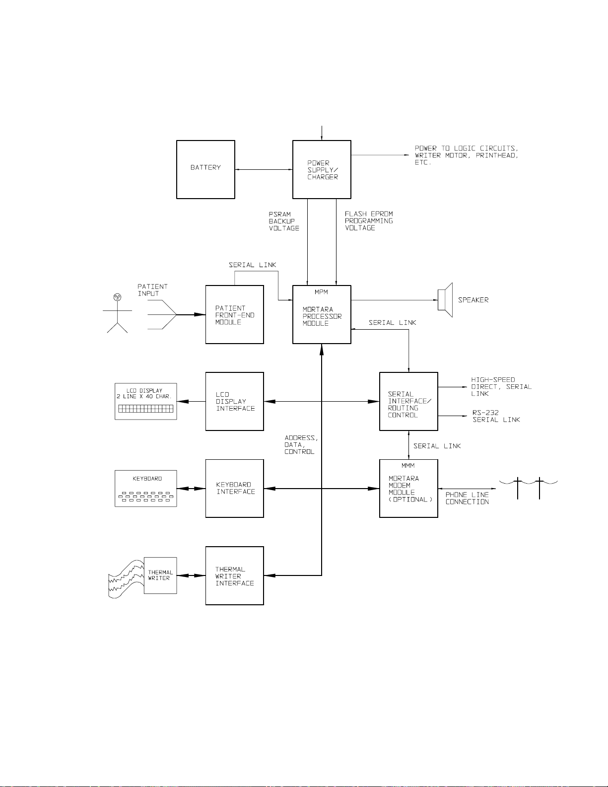
The MORTARA ELI 100 is an advanced interpretive electrocardiograph system utilizing the latest electronic
technology and software. The ELI 100 offers 12 lead patient ECG monitoring, a 2 line by 40 character LCD
display, a full function touchpad keyboard, a 4-inch thermal writer for printing waveforms and interpretive data, a
real-time electronic clock and calendar, an RS-232 level serial communications port, internal MODEM, a highspeed logic-level serial communications port, and internal power supply, batteries, and battery re-charge circuitry.
The system utilizes CMOS digital components to minimize power consumption and enhance performance. The ELI
100 is a modular assembly taking advantage of standard sub-assemblies designed at Mortara Instrument, Inc.
The system consists of the following major sub-assemblies and parts:
• Mortara Processor Module (MPM)
• Mortara MODEM Module (MMM) - optional.
• Main System board (Motherboard) Assembly
• Keyboard
• LCD Display
• Writer Assembly
• Batteries
• AC Input Power Selector and AC Power Switch Assemblies
• Various other Interconnect Cable Assemblies
The basic operation of each of the above will be covered in the following sections.
Processor Module (MPM)
The MPM is a propriety plug-in module forming the processing core of the ELI 100. This module, based on
the Motorola MC68332 micro-controller, controls all aspects of ELI 100 operation. The basic system bus
architecture and timing is derived from the 68332 local bus interface. This module is always installed in the
ELI 100.
The module contains RAM memory for processing and storage of ECGs, non-volatile memory for storage of
the micro-controller program and special configuration parameters, and a real-time clock chip for tracking timeof-day and date. The module also contains Mortara propriety integrated circuits (ICs) which receive and preprocess ECG data from the Front-End module. The Serial Communications Interface (SCI), a Universal
Asynchronous Receiver-Transmitter (UART) serial interface, is supported by the MPM and is used throughout
the ELI 100 for serial communications as described in later sections. The signal lines for this interface are
named TXD and RXD.
Modem Module (MMM)
The MMM is a propriety plug-in module which adds MODEM capabilities to the ELI 100. Currently, this
module is optional and may not be installed in all units.
The MMM is a 2400 baud MODEM conforming to v.21/v.22/v.22 bis and Bell 103/212A standards. Serial
data transmission and reception is accomplished via the MPM SCI (UART) interface. The MM accepts an
input (CH0) from the MPM for ON HOOK/OFF HOOK control. The MMM provides a RING INDICATE
output signal (CH1) for detection by the MPM.
3-1

ELI 100_____________________________________________________________________________
Main System Board
The main system board contains all the interfaces and support circuits required in the ELI 100 including system
bus support, RS-232 and high-speed serial communication ports, writer, keyboard, and LCD display interfaces,
patient cable connection and Front-End Module for ECG acquisition, power management circuit, and power
supply.
RS-232 Level Serial Port/High Speed Serial Port
The ELI 100 has one 9 pin sub-miniature "D" female connector on the back of the unit. Both RS-232 serial
communication and high-speed serial communication are available via this port. The RS-232 communication
data rate is programmable up to 38,400 bps or 57,600 bps when the ELI 100 is configured as a ST Monitor.
Note connector J11 on the ELI 100 schematics for the pin numbers used for RS-232 communication.
U21 and associated circuitry perform the required level shift conversion between logic voltage levels and RS232 compatible levels. The tri-state buffers (U8) which are controlled directly by the MPM determine the
source/destination of the serial data to this port.
High-speed data communication is also available at J11 (pins 1 and 9). This is a logic level serial port with
communication performed at 1.25Mbit/sec. The tri-state buffers (U8) controlled by the MPM are used to
connect the ISOLINK (U17) high-speed output to the external high-speed port.
Writer Interface
The writer interface consists of all support circuits required to run the writer. These include the motor control
circuit, printhead signal interface and printhead power interface.
Writer Motor Control
Q7, Q8 and associated circuits comprise the motor drive circuit. Motor speed is adjusted via the signal CH10,
which is a 10 KHz, variable duty-cycle, pulse-width modulated output of the MPM. In controlling the motor
speed, the higher the applied duty cycle, the faster the motor will turn. Signal CH9 serves as the brake FET
(Q6) control and printhead signal enable, while the inversion of this signal, CH9n, is an enable signal to the
motor drive circuit. The writer motor is connected to the J6 connector on the main system board.
Closed loop control of the motor speed is accomplished in software, using feedback from the motor's shaft
encoder, which is filtered by R88, C60 and received by U12. The motor encoder pulses cause this circuit to
generate interrupts (on IRQ6n) to the MPM. The interval between interrupts is a direct measure of the motor
speed, hence the writer paper speed. The MPM must reset this circuit by pulsing signal R34n after each
interrupt.
3-2

____________________________________________________________________________Section 3
Printhead Signal and Power Interface
The printhead signal interface is accomplished through the Mortara propriety Thermal Printhead gate array
(TPH_GA), U2. Static RAM chip U1 is used by the TPH_GA in performing dot hysteresis control. U20
simply buffers signals to the printhead, while RP5 forms a filter with the cable capacitance to help reduce EMI
emissions. The printhead cable (30 conductor, ribbon cable) plugs into connector J9 on the main system board.
All power and control signals required for controls of the printhead are carried through this cable.
The strobe-width adjust circuit (U18, D16, D17, D20, D21 and associated circuits) is designed to adjust the
length of the print strobe based on changin g conditions of printhead voltage and temperature. Stro be time will
lengthen as the printhead voltage, VHEAD, decreases. Strobe time will also lengthen as prin thead temperature,
as gauged by a thermistor on the printhead, decreases. The circuit attempts to match the "delivered energy per
pulse" curve as specified by the printhead manufacturer. This helps to ensure consistent quality printouts over a
wide range of operating conditions.
Power to the printhead "heater elements", the heat from which actually makes images appear on the paper, is
supplied to the writer via J9 (pins 2, 4, 6, 8, and 10). The system power supply provides power to the printhead
either directly from the batteries or from the AC supply (if AC power is connected), or under heavy printing
load, both sources. Capacitor C71 stores energy for the fast, heavy current surges required by the printhead.
VHEAD is a switched output (via Q16, Q17) which allows the voltage to be turned off by the MPM when the
printhead is not in use. The VHEAD current is limited to approximately 1.5 amps via R103 and Q5. Note that
D22, C64, and R102 are only provisional components and are not presently installed.
Keyboard Interface
Electrically, the keyboard is arranged as an 8 x 8 matrix, which is polled on a periodic basis to determine which
key(s) are being pushed. The keyboard cable plugs into connector J4 on the main system board.
The keyboard interface (U4, U6, RP2, RP4, and D1) allows the MPM to poll the keyboard for keypushes.
Polling is performed by MPM writes to the row driver latch (U4) which drive "ROW" signals (ROW 1 ROW8) to a "low" state one at a time. The code read subsequently from the "COLUMN" signals via U6
(COL1 - COL8), along with the knowledge of which ROW signal was driven low, indicates which key(s) in the
matrix are being pushed.
The COL8 is also input to the power management circuit which allows the unit to be powered on via the
keyboard ON/OFF key when operating from batteries alone.
The keyboard itself is mounted on the top cover with the interconnect cable extending through a slot to the
inside of the cover. The cable must be plugged into the J4 connector on the main system board as the top cover
is being placed on the unit.
The keyboard grounding plate is installed on the inside of the top cover at both the right and left sides of the
keyboard. With the cover installed on the unit, the plate contacts both the keyboard backplate and the chassis
to provide an affective path for conducting Electrostatic Discharge (ESD) pulses away from sensitive circuitry.
LCD Interface
The electrical interface to the LCD display is accomplished through the J1 connector on the main system board.
Interface signals CH6, CH5 (from the MPM) and CS_LCD (from the ISOLINK, U7) are the LCD Register
Select, Read/Write, and Enable signal, respectively. Series resistors R2 and RP1 form a filter with the cable
capacitance to help reduce EMI emissions. Resistors R4 and R6 set the contrast control voltage to the LCD
display.
3-3

ELI 100_____________________________________________________________________________
The 2 x 40 character LCD display is mounted on the inside of the top cover with the cable extending to the left
as the cover is viewed from the operator's normal viewing position. The active area of the LCD display is
visible through the protective plastic window directly above the keyboard. The LCD display cable must be
plugged into the J1 connector on the main system board as the top cover is being placed on the unit.
Patient Input
The patient cable is connected to the J2 connector on the left side of the unit. This is a 15 pin subminiature "D"
(female) connector. Patient signals are input to a propriety Front-End module (FE1) mounted on the main
system board. The Front-End module samples the input signals and digitized data is transmitted via
synchronous serial data stream to the MPM for processing, storage and printing.
Spark gap SG1 and resistor R24 allow a path for ESD currents applied to the patient inputs. R25 provides a
very low current discharge path to prevent build-up of excess charge on the cable shield.
Speaker Interface
The speaker (SP1) is a piezo element mounted on the main system board and driven by Q14, R35 and R30.
The CH15 signal from the MPM provides the waveform, under software control, to drive the speaker. Key
click "volume" setting is accomplished by altering the frequency, duty-cycle and/or duration of pulses to the
speaker.
Power Management Circuit
The power management circuit (U12, U13, U16, and associated components) control power flow in the ELI
100. This circuit provides the following functions:
• Keyboard power-on support.
• 5V (VCC) Logic supply power ON / OFF control.
• Hardware watchdog.
The keyboard power-on circuit senses the depression of the keyboard ON / OFF key and turns the 5V logic
supply ON. This circuit is powered from 5V (back-up power), which is available any time the batteries and
fuse are installed.
The 5V logic supply is automatically latched ON anytime AC power is applied. Furthermore, when AC power
is applied the logic supply can not be turned off.
The signal W24n, controlled by the MPM, is pulsed low to turn off logic supply. Pulses on this line will turn
the logic supply off only when AC power is OFF.
The hardware watchdog circuit is intended as a fail-safe to prevent deep discharge of the batteries and loss of
ECG data in the unlikely event of a processor error or other system reset. During normal operation, signal
WDOGn is pulsed by the MPM on a periodic basis, which continually resets the watchdog circuit. If WDOGn
pulses cease for a period of approximately 2 seconds, the watchdog circuits will time out and attempts to turn
off the logic supply.
3-4

____________________________________________________________________________Section 3
Power Supply
AC Input Power
AC power connected to the ELI 100 at the back of the unit using a suitable line cord. The voltage selector
tumbler setting and fuse ratings must match the voltage applied to the unit.
The AC power switch, located on the back of the unit must be in ON position to power the unit from the AC
source and to change batteries.
The AC power wiring connects to a mating connector on the main board (J8) which routes the AC input to the
primary side of the power transformer.
The transformer secondary side connects the AC power to the power supply circuits on the system board.
AC power is rectified via bridge B1 and filtered by C34. This is the raw DC supply used by the charger
supplies. R13, R14, R15, C18, and Q1 form an AC power detection circuit. The signal ACONn goes low to
turn on the logic supply when AC power is applied. This signal can also be read by the MPM.
Battery Connections
The three, 6V lead-acid gel-cell batteries are connected in series to form a nominal 18V-battery supply. The
positive lead from the batteries runs through the fuse at the back of the unit, and back to the connector on the
cable harness with the battery negative lead. Battery connection to the system board is made at the J10
connector.
This unit is capable of full operation from batteries.
Battery Charger and Printhead Supply
The battery charger and printhead supply (U14 and associated circuits), are controlled by the UC3906 battery
charger controller IC (U11 and associated circuits). This temperature compensated controller monitors
charging current and adjusts output voltage accordingly to control the charging profile of the batteries.
Nominal "float charge" voltage is approximately 20.55V, while high-end "bulk charge" voltage is
approximately 22.2V.
The same voltage applied to the batteries is also used to power the printhead heater elements during printing
operations (as described above).
U18, R77, R78, C49, R56 and D12 form the battery charging detector circuit. The signal CHARGEn will be
"low" when the batteries are being "bulk charged". When the charge controller switches to "float" mode,
CHARGEn will go high. This information is available to the MPM for status message purposes.
5V Logic Supply
The 5V logic supply (U10 and associated circuits) powers all the logic devices in the unit. This supply is
controlled by the power management circuit through FET switch combination Q2 and Q4.
3-5

ELI 100_____________________________________________________________________________
5V Back-up Supply
The 5V back-up supply (U9 and associated components) supplies power to devices which, must operate or save
memory when the 5V logic supply is off. The output voltage of this supply is a actually approximately 4.6
volts.
U9 also provides battery voltage monitoring support. Battery voltage is sensed through divider circuit R26,
R42, R31 and D9. The voltage is compared to a reference voltage inside U9 and U9 outputs the
LOBATTn signal, which can be read by the processor. Signal CH3 from the MPM serves to shift the compared
voltage to facilitate detection of two battery voltage levels. The higher voltage threshold is termed "battery
depleted". When the MPM detects "battery depleted", the software will power off th e unit.
12V Programming Supply
This supply (U17 and associated circuits) provides power used in programming FLASH memory devices on the
MPM card. This supply must be enabled by the MPM (signal 12VONn).
For some older equipment it may be necessary that MPM (signal 12VONn) enable the supply, but also requires
that the unit be "tilted" approximately 30 degrees from level. Mercury switch SW 1 is included to prevent
unintentional programming operations. Th 12V supply will remain disabled unless the unit is tilted.
3-6
____________________________________________________________________________Section 3
Block Diagram
A/C Power
3-7
ELI 100_____________________________________________________________________________
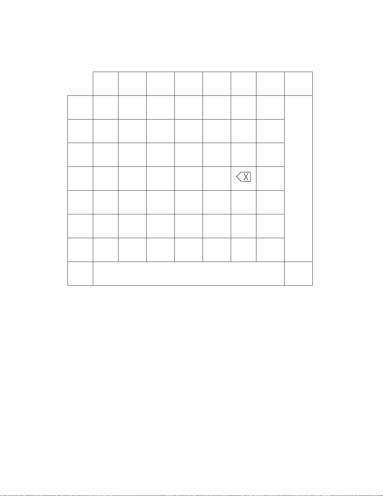
Keyboard Matrix
COLUMN
R
W
1 2 3 4 5 6 7 8
1 SPF Z X C V B N
2 SLT 0 3 4 7 8
3 1 2 5 6 9
4 E R U I
5 SHIFT Q W T Y O RHY
6 ENT D F J K P XMT
7 STOP A S G H L M
ECG
8
DC
ON
OFF
Battery Charging
The ELI 100 operates on AC power or on an internal battery which can be charged by doing the following:
Connect the ELI 100 to AC power using the power cord provided. Turn the power switch located on the back of the
ELI 100 to the ON position (1/0). The message: "CHARGING" or "AC POWER" will appear on the LCD screen.
If the message "AC POWER" remains on the display, verify that the battery fuse is installed and functional. If the
battery fuse is installed and functional and the display indicates "AC POWER", the batteries are fully charged.
To fully charge an ELI 100, the unit should be plugged in for approximately 8 hours, and, when fully charged, the
LCD will display "AC POWER", and the ELI 100 will operate continuously for approximately 4 hours.
When approximately 30 minutes of continuous operation remain in the unit, the message: "BATTERY LOW" will
appear on the LCD. When this message appears, printing is disabled, thus avoiding total battery discharge.
Connecting the unit to AC makes it possible to generate printouts. However, it is recommended that you leave the
unit in the CHARGING mode for some time before using it on battery power only.
Whenever possible, especially following extended use, the ELI 100 should be connected to AC Power and charged
when not in use.
3-8
____________________________________________________________________________Section 3
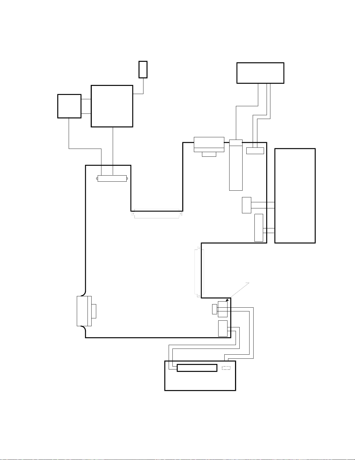
Interconnection Diagram 1
GROUND
LUG
BAT TERIES
AC
POWER
SWITCH
AC POWER
INLET
AND FUSES
J8
M M M
SLOT
J7
RS-232 / HIGH SPEED
SERIAL DATA
J11
M P M
J5
SLOT
J3 DEBUG
(UNUSED)
F1
J6
J10
J9
THERMAL
WRITER
MOTOR
PRINTHEAD
DATA /POWER
ECG
INPUT
J2
J4
J1
LCD DISPLAY
KEYBOARD
3-9

ELI 100_____________________________________________________________________________
Interconnection List
RS-232 / High-Speed Serial Data Port
Connector: Pin #: Name: Description:
J11 1 XROUT High-Speed Data Output
2 RX Receive Data
3 TX Transmit Data
4 DTR Data Terminal Ready
5 SHGND Ground Reference
6 ENMUX +5V for External Module
7 DSR Data Set Ready
8 CTS Clear to Send
9 XRIN High-Speed Data Input
AC Power Input
Connector: Pin #: Name: Description:
J8 1 AC1 T1 Primary #1
2 AC2 T1 Primary #1
3 AC3 T1 Primary #2
4 AC4 T1 Primary #2
5 THERM AC Input (Line)
6 ACP AC Input (Neutral)
Battery Input
Connector: Pin #: Name: Description:
J10 1 BATPLUS Positive Battery Terminal
2 BATNEG Negative Battery Terminal
Writer Motor
Connector: Pin #: Name: Description:
J6 1 GND Chassis Ground
2 VCC 5V Power for Shaft Encoder
3 TACH Motor Shaft Encoder Output
4 (NC)
5 GND Chassis Ground
6 MOTOR Writer Motor Power
7 (NC)
8 (NC)
9 (NC)
10 (NC)
3-10
 Loading...