

Cardinal VET-50 Owner's Manual
(
VET-50
VETERINARY SCALE
Owner’s Manual
CARDINAL SCALE MFG. CO.
1961-M008-O1 Rev C
11/06
Technical Support: Ph: 866-254-8261 v techsupport@cardet.com
PO BOX 151 v WEBB CITY, MO 64870
417) 673-4631 v FAX (417) 673-5001
PH
Web Site - www.detectoscale.com
Printed in USA


INTRODUCTION
Thank you for your purchase of our Detecto
VET-50 Electronic Veterinary Scale. It was
built with Detecto quality and reliability at our
factory in Webb City, Missouri. This manual
will guide you through installation, and
operation of your scale. Please read it
thoroughly before attempting to operate this
scale and keep it handy for future reference.
FCC COMPLIANCE STATEMENT
WARNING! This equipment generates uses
and can radiate radio frequency and if not
installed and used in accordance with the
instruction manual, may cause interference to
radio communications. It has been tested
and found to comply with the limits for a Class
A computing device pursuant to Subpart J of
Part 15 of FCC rules, which are designed to
provide reasonable protection against such
interference when operated in a commercial
environment. Operation of this equipment in
a residential area may cause interference in
which case the user will be responsible to
take whatever measures necessary to correct
the interference.
You may find the booklet "How to Identify and
Resolve Radio TV Interference Problems"
prepared by the Federal Communications
Commission helpful. It is available from the
U.S. Government Printing Office, Washington,
D.C. 20402. Stock No. 001-000-00315-4.
All rights reserved. Reproduction or use, without
expressed written permission, of editorial or pictorial
content, in any manner, is prohibited. No patent
liability is assumed with respect to the use of the
information contained herein. While every precaution
has been taken in the preparation of this manual, the
Seller assumes no responsibility for errors or
omissions. Neither is any liability assumed for
damages resulting from use of the information
contained herein. All instructions and diagrams have
been checked for accuracy and ease of application;
however, success and safety in working with tools
depend to a great extent upon the individual accuracy,
skill and caution. For this reason the Seller is not able
to guarantee the result of any procedure contained
herein. Nor can they assume responsibility for any
damage to property or injury to persons occasioned
from the procedures. Persons engaging the
procedures do so entirely at their own risk.
Serial Number_______________________
Date of Purchase ____________________
Purchased Form_____________________
___________________________________
___________________________________
RETAIN THIS INFORMATION FOR FUTURE USE
TABLE OF CONTENTS
INTRODUCTION …………………………… 1
SPECIFICATIONS …………………………. 1
UNPACKING INSTRUCTIONS …………… 2
INSTALLATION …………………………….. 2
Installing the Deck ………………………. 2
Interconnections …………………………. 2
Scale Base Connection …….…………… 2
Power Supply …………………………..... 3
Batteries ………………………………….. 3
Battery Operation ...……………………… 3
Battery Charging …..…………………….. 3
Battery Installation/Replacement ………. 3
OPERATION ………………………………… 5
ERROR AND STATUS DISPLAYS ………. 6
BEFORE YOU CALL SERVICE …………... 6
CARE AND CLEANING ……………………. 7
PARTS IDENTIFICATION …………………. 8
Power ………………
Requirements
Platform Size ……… 12" x 14" x 3"
Capacity …………… 50 lb x .02 lb
Operating …………..
Temperature
Shipping Weight ….. 25 lb
PRECAUTIONS
Before using this instrument, read this
manual and pay special attention to all
"WARNING" symbols:
SPECIFICATIONS
6 “AA” size Alkaline,
Ni-Cad or NiMH
batteries (not included)
OR an optional 100 to
240 VAC 50/60Hz 12
VDC 1A wall plug-in
UL/CSA listed AC
power supply.
Stainless Steel with
Pad
(20 kg x .01 kg)
14º to 104º F
(-10º to +40º C)
IMPORTANT ELECTRICAL
WARNING
1961-M008-O1 v VET-50
Page 1
pply
The VET-50 is shipped in two (2) cartons. One carton will contain the weight indicator and the
other carton will house the scale base (with 8 ft. coiled cable), the Stainless Steel deck, the
rubber mat, and the Desk stand/Wall mount bracket for the indicator.
Before starting to assemble, please unpack carefully and remove all wrappings and fillers.
Inspect the unit for any signs of damage due to shipping, such as exterior dents and scratches.
It is the responsibility of the Purchaser to file all claims for any damages or loss in transit
incurred. Retain packing and shipping carton for return of scale if necessary.
UNPACKING INSTRUCTIONS
INSTALLATION
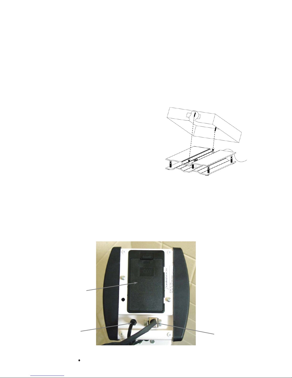
Installing the Deck
To install the Stainless Steel deck on the scale,
place the scale base in front of you on a desk or
table with the slotted end to your right. Tilt the deck
to a 45° angle and slide the deck over the base
aligning the pin on the bottom of the deck with the
slot in the scale base. Lower the left side of the
deck onto the base aligning the pin with the hole in
the scale base. Refer to Figure No. 1.
Interconnections
Both the VET-50 scale base and power connections
to the weight indicator are made at the bottom rear
panel of the indicator. Refer to Figure No. 2 for the
rear panel layout.
Figure No. 1
Scale Base Connection
The scale base connection to the weight indicator is made via an 8 ft. coiled cable with a
modular type connector on one end and a 9-pin "D" type connector on the other. The modular
connector of the coiled cable should be inserted into the mating connector socket on the scale
base until it locks into place. The 9-pin connector plugs into a 9-pin "D" type jack located on
the bottom rear panel of the indicator and is secured by two (2) screws.
Battery
Cover
1961-M008-O1 v VET-50
Power
Su
Scale
Base
Cable
Figure No. 2
Page 2
INSTALLATION, Cont.
Power Supply
To power the weight indicator without batteries, connect the 12 VDC, 1 Amp power supply’s
connector into the power jack on the lower back of the indicator and then plug the power
supply into the proper electrical outlet. See Figure 2. On models requiring 220 VAC, it is the
customer’s responsibility to obtain the correct power adapter plug. The scale is now ready for
operation.
NOTE! The power supply is also used to recharge the batteries, when
the weight indicator is operated from Ni-Cad or NiMH batteries.
Batteries
Battery operation is a standard feature of the weight indicator, although the batteries are
optional (not included). The indicator can be operated from 6 "AA" size Alkaline, Ni-Cad or
NiMH batteries. You must first obtain and install batteries before operations can begin.
Batteries are contained in a battery holder inside the indicator. Access is via a removable
panel on the back of the indicator.
When using batteries, all 6 batteries must be of the same type. They must be all Alkaline,
Ni-Cad or all NiMH. In addition, DO NOT mix Ni-Cad or NiMH batteries.
CAUTION! The weight indicator has internal circuitry that when used in
conjunction with the external power supply, recharges the Ni-Cad or NiMH
batteries. Because the indicator has this charging capability, DO NOT connect a
power supply to the indicator if using Alkaline batteries.
Battery Operation
The weight indicator will operate for up to 250 hours on new Alkaline batteries or for up to 100
hours on fully charged Ni-Cad or NiMH batteries depending on the condition of the batteries
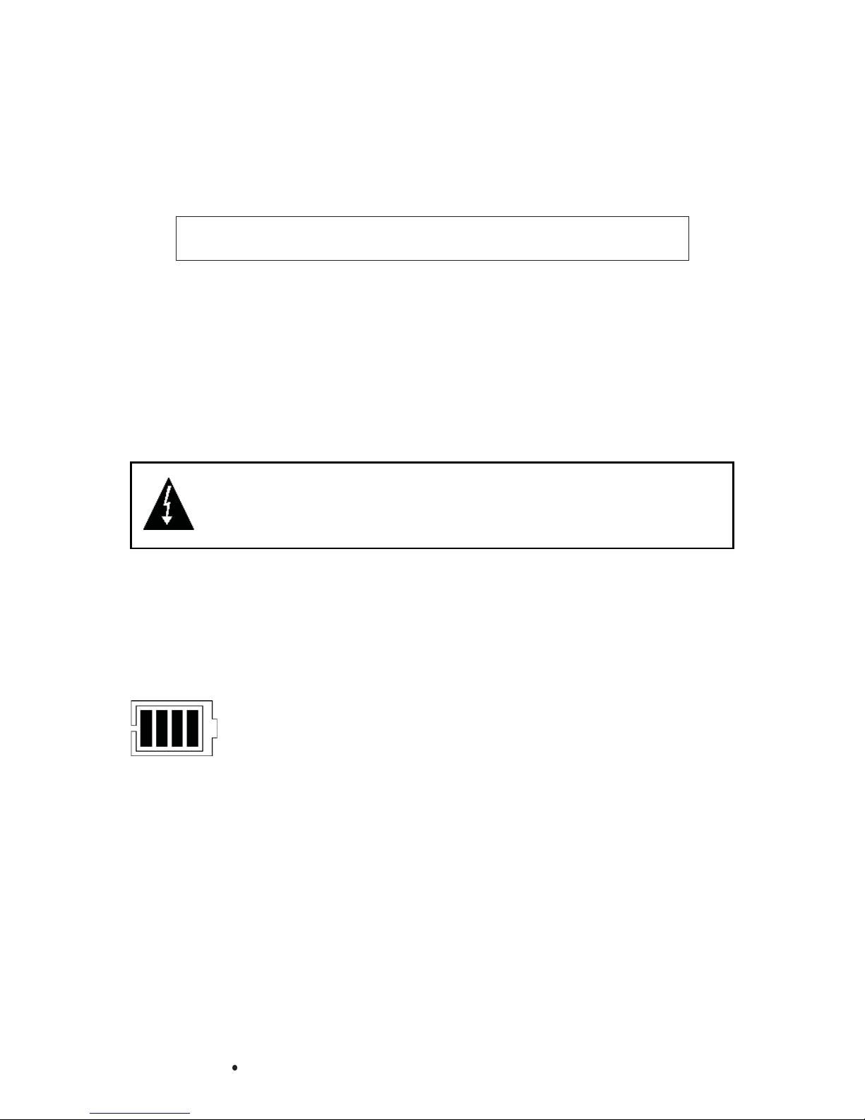
(from new to about 500 recharges). The battery bar graph on the display indicates the battery
capacity in 4 steps:
4 segments - the full battery capacity is available,
3 segments - the battery is at 75% of capacity,
2 segments - the battery is at 50% of capacity,
1 segment: - the battery is at 25% capacity.
When the battery voltage drops too low for accurate weighing, the indicator will show "7<
and then shut off. You will be unable to turn the indicator back on until the Alkaline batteries
have been replaced or the AC power supply is connected to the display to operate it and
recharge the Ni-Cad or NiMH batteries.
Battery Charging
To recharge the Ni-Cad or NiMH batteries, the AC power supply must be connected to a power
outlet and plugged into the indicator. It will take approximately 8 to 10 hours to fully recharge
the batteries in the display. Charging the batteries for more than 10 hours will not damage
them. NOTE! The indicator may be operated while the batteries are charging.
1961-M008-O1 v VET-50
Page 3
 Loading...