

Page 1
Physician’s Scale
Eye-Level Beam Scale
Operation Instructions
CARDINAL SCALE MFG. CO.
8525-M063-O1 Rev G PO Box 151 y Webb City, MO 64870
10/08 Ph: 417-673-4631 y Fax: 417-673-5001 Printed in USA
www.detectoscale.com
Technical Support: Ph: 866-254-8261 y techsupport@cardet.com
Page 2
Column Bracket
Soporte de la columna
Opening
Abertura
2
3
1
4
Optional
Detecto Physician's Scale
Assembly Instructions
This precision instrument is
extremely easy to set up as
all major parts are factory preassembled. Before starting to
assemble, please unpack carefully
and remove all wrappings and
fillers. Carton contains:
1) Column with head.
2) Platform base.
3) Hand post. - optional
4) Height measuring
rod. - optional
5) Hardware kit
6) Wheels - optional
1
Balanza para médicos
Instrucciones de armado
Este instrumento de precisión es
facilísimo de armar ya que todos
los componentes principales son
ensamblados de antemano en la
fábrica. Antes de empezar, favor
de desempacar cuidadosamente
y quitar todas las envolturas y
material de empaque. La caja
contiene:
1) Columna con cabezal;
2) Plataforma con base;
3) Poste de Mano;
4) Vara de medir;
5) Juego de hardware;
6) Ruedas - opcional.
2
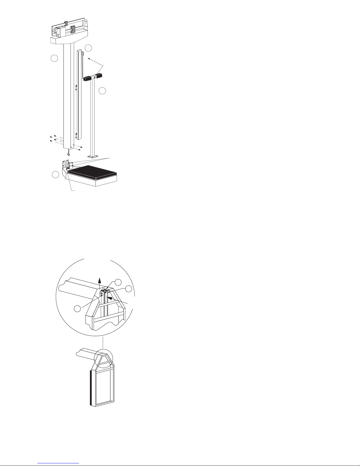
NOTE! If column bracket is bent,
straighten before assembling.
1) Unpack platform base
from box and plastic bag.
2) Lay platform base
upside down and remove
all cardboard packing
and hardware kit from
bottom of scale base.
3) Flip scale base over.
4) Slip column over column
bracket on platform base.
Hold column straight so
that draft rod enters
opening in column
bracket. Screw column
to column brackets
(two 1/4 hex head screws
in front of column, four in
back).
! Si el soporte esta doblado
enderescalo antes de
ensamblar la balanza.
1) Desempaque la base de
la plataforma de su caja
y funda plástica.
2) Recuesta la base de
la plataforma al revés
y remueva los empaques
de cartón y el juego de
hardware del mismo.
3) Voltee la base de la
báscula.
4) Pasar la columna por encima
del soporte de la columna en
la base de la plataforma.
Sostener recta la columna
para que la vara de acero
entre en la abertura del
soporte de la columna.
Atornillar la columna a la
escuadra de la columna (dos
tornillos hexagonales de 1/1
en frente de la columna, y
cuatro en la parte de atrás).
3
Lay down scale, with column
horizontal to floor (using a table
top).
1) Raise draft rod keeping
out of lever's way.
2) Push lever
3) When lever is in position,
hook draft rod around
pivot.
Poner la balanza horizontalment
sobre una mesa.
1) Levantar la vara de
acero manteniendola
alejada de la palanca.
2) Empujar la palanca
3) Cuando la palanca este
en posición, enganche la
vara de acero alrededor
del pivote.
Raise
draft
rod
Push
lever
2
3
1
Page 3
B
C
D
G
E
F
H
A
4
5
6
7
Poises
Pesas
Balance Screw
Tornillo de la
balanza
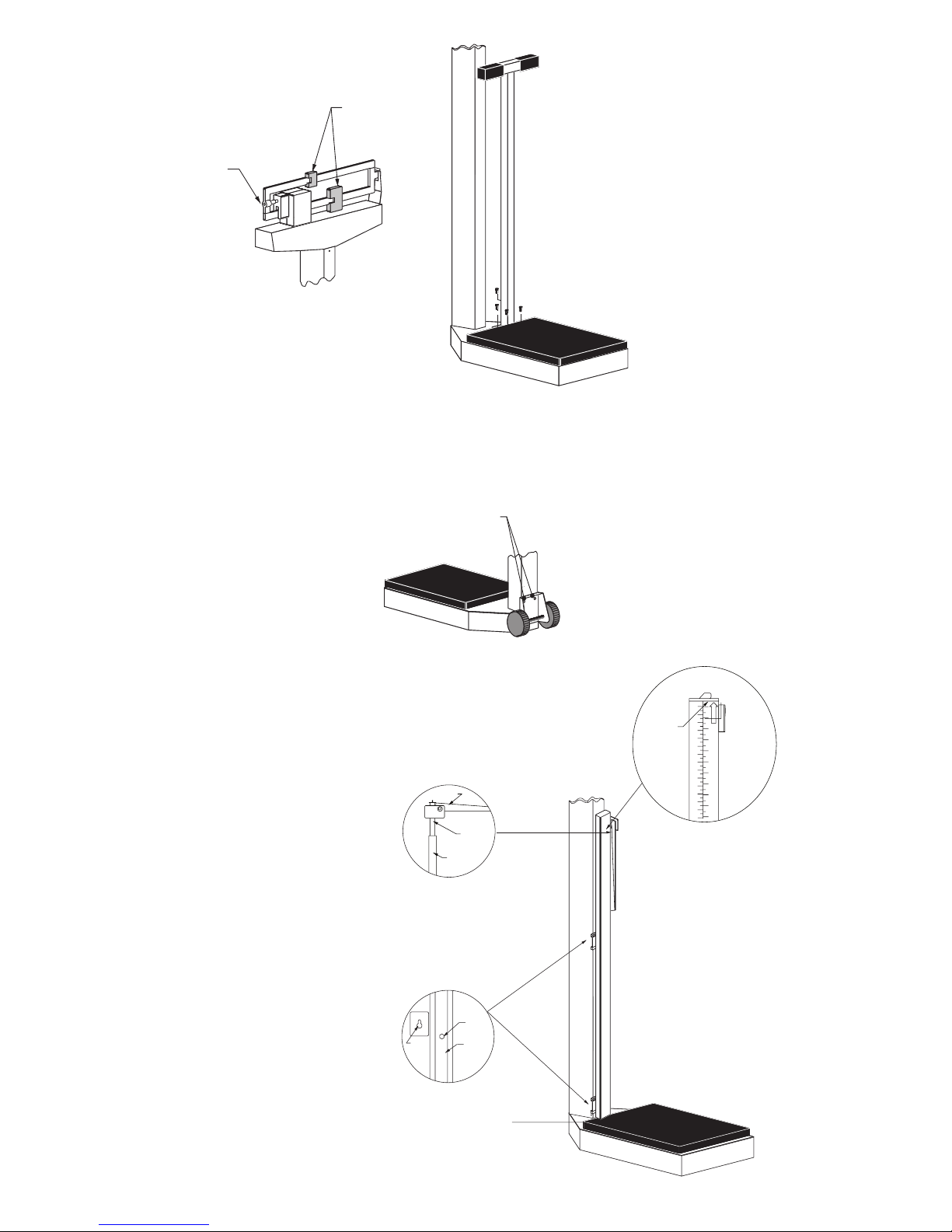
Screws and wheel
bracket
Optional Hand Post
Use the four screws to attach the hand
post to the platform base.
Use cuatro (4) tornillos para pegar
el poste de mano a la base de la
plataforma.
To balance scale, move both poises
to zero (0) and turn balance screw to
right or left until scale balances. For
accurate weighing, place scale on level
floor.
Para poner la balanza en fiel, mover
las dos pesas corredizas a cero (0)
y girar el tornillo de la balanza hacia
la derecha o izquierda hasta que
la balanza quede equilibrada. Para
pesadas exactas, colóquese la balanza
en suelo a nivel.
Optional Wheels
How to setup the Detecto Physician's
scale with roller wheels.
Use the two screws in the back of the
column to attach the wheel bracket.
Como arma la Detecto balanza para
médicos con ruedas.
Use los dos tomillos en la parte atras de
la columna para pegar el soporte de la
rueda a la columna.
Optional Height Rod
A = “Read” line
B = Spoon
C = Inner height rod
D = Outer height rod
E = Hex head screw
F = Column
G = Mounting bracket
H = Height rod sits on top of
the scale base
Opcional Varilla Medidora
A = Linea de lectura
B = Cuchara
C = Varilla medidora interna
D = Varilla medidora externa
E = Tornillos de cabezas
hexagonales
F = Columna
G = Soporte
H = La varilla medidora debe
descansar sobre la base
de la bascula como se ve
en el dibujo
Height Rod in “rest”
position
Varilla medidora
en posicion de
descanso
Page 4

Optional Height Rod Installation:
1. Remove the height rod from the box.
2. If not already installed, insert the two hex
head screws from the hardware pack into the
holes in the front of the column and tighten
them with the included wrench until the hex
heads are 1/8" from the column.
3. Place both height rod brackets over the two
pre-installed hex head screws and pull down.
4. Use the included wrench to tighten both hex
head screws. Do not overtighten the screws.
Height Rod Operating Guide:
1. Before the person steps onto the scale
platform, the spoon should be rotated to the
horizontal position, and raised well above the
person’s apparent height.
2. The person may now step onto the scale
platform. The spoon should be held
horizontal and above the person’s head.
3. Carefully lower the spoon, while keeping it
horizontal, until it rests gently upon the top of
the person’s head. If the person is shorter
than 3' 4" (101.5 cm), push the latch to the
right, while simultaneously pushing down on
the spoon, until the spoon rests horizontally
upon the top of the person’s head.
4. Read the height of the person as follows:
If the back of the spoon points to the
outer height rod, then it points to the
correct height.
If the back of the spoon points to the inner
height rod, then the correct height is read
at the top of the outer height rod (see
“Read” arrow on the outer height rod).
5. While holding the spoon horizontally, raise
the spoon above the person's head. The
person may now step off of the scale
platform. Hold the spoon horizontal until the
person is clear of the height rod.
6. Rotate the spoon back to the vertical position
and adjust the height rod back to the rest
position (i.e. the spoon should be locked in
place within the inner height rod and the
inner rod should be at its lowest position).
Instalacion de la Barra Medidora de Altura:
1. Remueva el tallímetro de la caja.
2. Si no estan instalados, coloque los tornillos
con cabezas hexagonales en los huecos al
frente de la columna y atornillelos con la
llave incluida en el paquete de partes, hasta
que sus cabezas quenden aproximadamente
1/8" de pulgada (3mm) de la columna.
3. Coloque los dos soportes de la barra
medidora en los tornillos ya instalados y tire
de los soportes hacia abajo.
4. Termine de atornillar sin apretarlos demasiado.
Como Usar La Barra Medidora:
1. Antes de subir a la plataforma, la cuchara
debe rotarse hacia la posicion horizontal y
colocarse a una altura superior a la que
aparenta la persona.
2. La persona ya puede subir a la plataforma y
la cuchara debe mantenerse horizontalmente
sobre la cabeza.
3. Bajando la cuchara cuidadosa y
horizontalmente, deje que caiga suavemente
sobre la cabeza. Si la altura de la persona es
menos de 3 pies y 4 pulgadas (101.5 cm),
empuje el pestillo hacia la derecha al mismo
tiempo que empuja la cuchara hacia abajo
hasta que la cuchara descanse sobre la
cabeza de la persona.
4. Lea la altura de la persona de la siguiente
manera:
Si la parte posterior de la cuchara señala
hacia la barra medidora exterior, esta
indicando la altura correcta.
Si la parte posterior de la cuchara señala
hacia la barra medidora interior, entonces
la lectura correcta debe hacerse al tope de
la barra medidora exterior (note la flecha y
la palabra “Read” en la barra medidora
exterior).
5. Mientras mantiene la cuchara en la posicion
horizontal, levantela de la cabeza de la
persona. La persona ya puede bajarse de la
plataforma. Mantenga la cuchara
horizontalmente hasta que la persona haya
bajado de la balanza.
6. Rote la cuchara hacia la posicion vertical y
ajuste la barra medidora en su posicion de
descanso (la cuchara debe estar firme en su
lugar y dentro de la barra medidora interna y
esta debe estar en su posicion mas baja).
Page 5

11
13
14
14
2
7
6
5
4
1
23
9
12
22
10
20
29
3
27
18
24
24
34
21
8
32
31
30
35
Item Part Part Name Req’d
1 3P1001X Base Weldment 1
2 0033-D244-0A Headpiece & Column Weldment 1
3 3P2011X Platform Weldment 1
3P5011X Platform Weldment (handpost) 1
4 3P8068 Mat (removable) 1
3P9068 Mat (handpost) 1
5 0033-C106-1A Hand Post Assembly 1
6 0033-D063-1A Measuring Rod Assy in/cm 1
7 0033-B333-08 Draft Rod 1
8 0033-C369-0A Shelf Lever w/Pivot 1
9 3P8002X Long Lever Assembly 1
10 3P8003X Short Lever Assembly 1
11 0033-B220-0A Beam 400 lb 1
0033-B227-1A Beam 180 kg 1
0033-B226-0A Beam 400 lb/175 kg 1
12 3P60 Check Plate 2
13 3P41 Reading Beam Retainer 1
14 0033-C236-08 Beam Cover 2
17* #10 Internal Tooth Lockwasher 2
18 #10-32 x 1/2 lg. hex head screw 2
19* #10-32 Square Nut 2
20 3P1008 Beam Yoke 1
21 3P8059 Union Hanger 4
22 2U58 Union Center Hanger 1
23 3P2087 Platform Bearing 4
24 1/4 - 20 x 3/4” lg. truss head Screw 10
25* 1/4 Split Lockwasher 10
26* 63K1038 Base Leg 4
27 #6 x 1/4 lg. hex head type “B”
Screw 2
28* 650RC7 Flatwasher 2
29 3P8034 Beam Hanger Side 2
30 6028-0105 Pin 2
31* 6024-0014 Flat Washer 1
32* 6009-5094 Hair Pin Cotter 2
33* 0033-B033-08 Wrench 1
34 #10 x 1/2 hex washer head type “B”
Screw 2
35 0033-B334-08 Hanger 2
*Not Shown
REPLACEMENT PART IDENTIFICATION
Page 6

STATEMENT OF LIMITED WARRANTY
Detecto Scale warrants its equipment to be free from defects in
material and workmanship as follows: Detecto warrants to the
original purchaser only that it will repair or replace any part of
equipment which is defective in material or workmanship for a
period of one (1) year from date of shipment. Detecto shall be the
sole judge of what constitutes a defect.
During the first ninety (90) days Detecto may choose to supply all
necessary replacement parts and service during normal weekday
working hours at no charge to the buyer.
After the first ninety (90) days Detecto will supply parts and
service at the job site provided the owner agrees to pay the Dealer
for all travel time, including mileage and test equipment, as well as
any expenses incurred over the direct labor of the technician at the
j
ob site. This limited warranty honors only labor performed by
Detecto authorized dealers.
This warranty does not apply to peripheral equipment not
manufactured by Detecto; this equipment will be covered by certain
manufacturer’s warranty only.
This warranty does not include replacement of expendable or
consumable parts. This does not apply to any item which has
deteriorated or damaged due to wear, accident, misuse, abuse,
improper line voltage, overloading, theft, lightning, fire, water or acts
of God, or due to extended storage or exposure while in purchaser’s
possession. This warranty does not apply to maintenance service.
Purchased parts will have a ninety (90) day repair or replacement
warranty only.
Detecto may require components be returned to the factory; they
must be properly packed and shipping charges prepaid. A return
authorization number must be obtained for all returns and marked
on the outside of all returned packages. Detecto accepts no
responsibility for loss or damage in transit.
Page 7

STATEMENT OF LIMITED WARRANTY
Conditions Which Void Limited Warranty
This warranty shall not apply to equipment which:
A.) Has been tampered with, defaced, mishandled or have had
repairs and modifications not authorized by Detecto.
B.) Has had serial number altered, defaced, or removed.
C.) Has not been grounded according to Detecto’s recommended
procedure.
Freight Carrier Damage
Claims for equipment damaged in transit must be referred to the
freight carrier in accordance with freight carrier regulations.
This warranty sets forth the extent of our liability for breach of any
warranty or deficiency in connection with the sale or use of the
product. Detecto will not be liable for consequential damages of any
nature, includin
g
but not limited to, loss of profit, delays or expenses,
whether based on tort or contract. Detecto reserves the right to
incorporate improvements in material and design without notice and
is not obligated to incorporate improvements in equipment
previously manufactured.
The foregoing is in lieu of all other warranties, express or implied
including any warranty that extends beyond the description of the
product including any warranty of merchantability or fitness for a
particular purpose. This warranty covers only those Detecto
products installed in the forty-eight (48) contiguous continental
United States.
Ph. (800) 641-2008
E-mail: detecto@cardet.com
203 E. Daugherty
Webb City, MO 64870
02/06
Printed in USA
D268-WARRANTY-DET
Page 8

 Loading...