

Cardinal PD100, PD200, PD300, PD300DHR, PD300MHR Owner's Manual

ProDoc Series
Digital Physician Scale
PD100
PD200
PD300
PD300DHR
(Digital Height Rod)
and
PD300MHR
(Mechanical Height Rod)
Owner’s Manual
CARDINAL SCALE MFG. CO.
0044-M340-O1 Rev C PO Box 151 Webb City, MO 64870
07/11 Ph: 417-673-4631 Fax: 417-673-5001
www.detectoscale.com
0044-M340-O1 Rev C ProDoc Series
1
Technical Support: Ph: 866-254-8261 techsupport@cardet.com
Technical Support: Ph: 866-254-8261 techsupport@cardet.com

0044-M340-O1 Rev C ProDoc Series
2

TABLE OF CONTENTS
INTRODUCTION ......…………………………………………………………………………….
1
SPECIFICATIONS ……………………………………………………………………………….
1
Standard Features …..…………………………………………………………………….…
1
PD100 …………………………………………………………………………………………….. 3
Unpacking ……………………………………………………………………………………. 3
Assembly ……………………………………………………………………………………... 3
Quick Start ……………………………………………………………………………………. 3
Placing the Scale …………………………………………………………………………..… 4
Placing the Display ….……………………………………………………………………..… 4
Wall Mounting ……………………………………………………………………………. 4
Desk or Table Mounting …………………………………………………………………. 6
PD200 …………………………………………………………………………………………….. 7
Unpacking ……………………………………………………………………………………. 7
Assembly ……………………………………………………………………………………... 7
Quick Start ……………………………………………………………………………………. 7
PD300 …………………………………………………………………………………………….. 9
Unpacking ....…………………………………………………………………………………. 9
Assembly ..………………………….………….…………………………………………...... 9
Quick Start ………………………………………………………………………………….… 11
PD300DHR ..……………………………………………………………………………………... 12
Digital Height Rod Installation ……………………………………………………………… 12
PD300MHR ...…………………………………………………………………………………….. 14
Mechanical Height Rod Installation ………………………………………………………… 14
BATTERY OPERATION ...…………...…………….…………………………………………… 16
Installation/Replacement .………………….……………………………………………..… 16
Low Battery …………………………………………………………………………………… 17
Automatic Shutoff ……………………………………………………………………….…… 17
Sleep Mode …………………………………………………………………………………… 17
OPTIONAL AC POWER ADAPTOR .……….………………………………………………… 17
OPERATION …………………………………….……………………………………………..… 18
Keypad Functions ………………………….………………………………………………… 18
Annunciators ……………………………….………………………………………………… 20
Basic Weighing .……………………………………………………………………………… 21
Weighing with Height and BMI Measure …………………………………………………… 22
With Digital Height Rod ………….……………………………………………………… 22
With Mechanical Height Rod or No Height Rod ……………………………………… 23
Storing W eight with the STORE Key ……………..……………………………………… 24
Recalling Weight with the RECALL Key ………………………………………………… 25
SETUP ……………….…………………………………………………………………………… 26
CALIBRATION ..……….………………………………………………………………………… 27
EVENT COUNTER ………………………………………………………………………………
29
DISPLAY MESSAGES …..………………………………………………………………………
30
TROUBLESHOOTING …..………………………………………………………………………
30
CARE AND CLEANING …......……………………………………………………………….…
31
0044-M340-O1 Rev C ProDoc Series
3
Proper Disposal
When this device reaches the end of its useful life, it must be properly disposed of. It must not be
disposed of as unsorted municipal waste. Within the European Union, this device should be
returned to the distributor from where it was purchased for proper disposal. This is in
accordance with EU Directive 2002/96/EC. Within North America, the device should be
disposed of in accordance with the local laws regarding the disposal of waste electrical and
electronic equipment.
It is everyone’s responsibility to help maintain the environment and to reduce
the effects of hazardous substances contained in electrical and electronic
equipment on human health. Please do your part by making certain that the
device is properly disposed of. The symbol shown to the right indicates that
this device must not be disposed of in unsorted municipal waste programs.
FCC Compliance Statement
WARNING! This equipment generates uses and can radiate radio frequency and if not installed
and used in accordance with the instruction manual, may cause interference to radio
communications. It has been tested and found to comply with the limits for a Class A computing
device pursuant to Subpart J of Part 15 of FCC rules, which are designed to provide reasonable
protection against such interference when operated in a commercial environment. Operation of
this equipment in a residential area may cause interference in which case the user will be
responsible to take whatever measures necessary to correct the interference.
You may find the booklet "How to Identify and Resolve Radio TV Interference Problems"
prepared by the Federal Communications Commission helpful. It is available from the U.S.
Government Printing Office, Washington, D.C. 20402. Request stock No. 001-000-00315-4.
All rights reserved. Reproduction or use, without expressed written permission, of editorial or
pictorial content, in any manner, is prohibited. No patent liability is assumed with respect to the
use of the information contained herein. While every precaution has been taken in the
preparation of this manual, the Seller assumes no responsibility for errors or omissions. Neither
is any liability assumed for damages resulting from use of the information contained herein. All
instructions and diagrams have been checked for accuracy and ease of application; however,
success and safety in working with tools depend to a great extent upon the individual’s accuracy ,
skill and caution. For this reason the Seller is not able to guarantee the result of any procedure
contained herein. Nor can they assume responsibility for any damage to property or injury to
persons occasioned from the procedures. Persons engaging the procedures do so entirely at
their own risk.
___________________________________
RETAIN THIS INFORMATION FOR FUTURE USE
___________________________________
Purchased From_____________________
___________________________________
Date of Purchase ____________________
Serial Number_______________________
PRECAUTIONS
Before using this scale, read this manual
and pay special attention to all "WARNING"
symbols:
IMPORTANT ELECTRICAL
WARNING
0044-M340-O1 Rev C ProDoc Series
4
INTRODUCTION
Thank you for purchasing our Detecto ProDoc Series Digital Physician Scale. Your scale has
been designed for simple and straightforward use and to assure accuracy and dependability for
years to come.
Please read this manual thoroughly before attempting to use your scale and keep it handy for
future reference. It contains important instructions for installation and proper operation of your
scale.
SPECIFICATIONS
Model Number ………………… PD100 (Floor Scale with Remote Display)
PD200 (Floor Scale
PD300 (Eye-Level Scale)
PD300DHR (Eye-Level Scale with Digital Height Rod)
PD300MHR (Eye-Level Scale with Mechanical Height Rod)
Capacity ...……………………….. 480 lb x 0.2 lb (220 kg x 0.1 kg)
Weight Units ......………………… Pounds or Kilograms (selectable)
Power Requirements …………… Six (6) “AA” size Alkaline batteries (not included) OR an
optional Medical device 9V AC/DC wall plug-in adapter
(Cardinal part number PD-AC, includes USA plug). Also
available UK plug (PD-UKPLUG) or EU plug (PD-EUPLUG).
Display …………………………… Five digit, seven segment, 1.0 inch (25 mm) high LCD
Operation Temperature ………… 50 to 104 ºF (+10 to +40 ºC)
Function Keys …………………… ZERO, UNITS, LOCK/RELEASE, BMI HEIGHT/ENTER,
RECALL, STORE and ON/OFF
Dimensions
PD100 Display ..……..........
Base ……………....
PD200 ……………………….
PD300 ……………………….
PD300MHR …………………
PD300DHR ………...............
5.25” H x 7.87” W x 2.125” D (134 mm x 200 mm x 54 mm)
3.33” H x 12.5” W x 13.0” D (85 mm x 318 mm x 330 mm)
8.75” H x 12.6” W x 16.9” D (222 mm x 320 mm x 430 mm)
48.0” H x 12.6” W x 17.0” D (1219 mm x 320 mm x 433 mm)
48.0” H x 14.0” W x 17.0” D (1219 mm x 354 mm x 433 mm)
48.0” H x 14.0” W x 17.0” D (1219 mm x 354 mm x 433 mm)
Shipping Weight …..……………. PD100 = 16.75 lb (7.60 kg)
PD200 = 21.16 lb (9.60 kg)
PD300 = 33.06 lb (15.00 kg)
PD300DHR = 39.68 lb (18.00 kg)
PD300MHR = 39.68 lb (18.00 kg)
Standard Features:
Metric Conversion (Weight and Height)
Body Mass Index (BMI) Calculator
Memory Function (Store and Recall up to four weights)
Selectable Sleep-Mode (up to 9 minutes)
Selectable Auto Shut-Off Feature (up to 9 minutes)
Level Indicator
0044-M340-O1 Rev C ProDoc Series
1

This page intentionally left blank.
0044-M340-O1 Rev C ProDoc Series
2

PD100
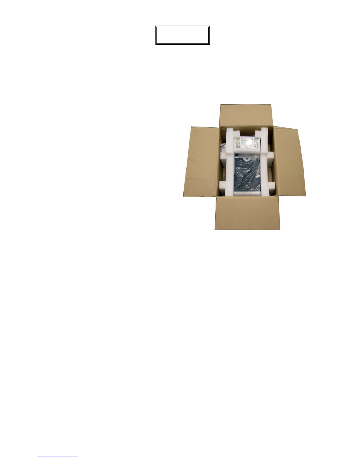
Unpacking
Remove the scale base, display, hardware pack and other components from the shipping
carton. After removing from the carton, check for any damage that may have taken place during
shipment. Keep and use the original carton and packing material for return shipment if it should
become necessary. The purchaser is responsible for filing all claims for any damages or loss
incurred during transit. Remove all plastic wrapping, foam fillers and cardboard material from
the scale base, display and other components. You should have the following components:
(1) Scale Base
(1) Remote Display
(1) Wall Bracket “A”
(includes four (4) feet for desk or table mounting)
(1) Wall Bracket “B”
(1) Hardware Pack, containing:
(2) M3.0x25 Screws and plastic wall anchors
M3.0x25 Screw
Plastic Wall Anchor
Assembly
The PD100 does not require any assembly. After installing batteries, the scale is ready for
operation.
Quick Start
Although it is recommended that you read this manual before attempting to operate the scale,
this section is included to provide a condensed set of instructions on installing and using the
scale. At a minimum, please make certain you read all of the caution and warning statements.
Step 1. Place the scale on the floor and then place the display at a convenient distance
from the scale base.
Step 2. Turn the scale over on the floor and then locate the battery access cover on the
bottom of the scale.
Step 3. Remove the cover, install six (6) “AA” size batteries
1
and then replace the cover.
Step 4. Turn the scale over to the normal operating position and make sure it is level.
Step 5. Press the ON/OFF key to turn the scale on.
2
Step 6. When the display is showing 0.0, have to patient step on the scale.
Step 7. Wait a few seconds for the weight to display and then read the patient’s weight.
Step 8. Patient may now step off scale.
Step 9. Press the ON/OFF key to turn the scale off.
1
See page 16 for detailed instructions on installing the batteries.
2
For complete Operation and Setup instructions, refer to pages 18 to 26.
0044-M340-O1 Rev C ProDoc Series
3
PD100
Placing the Scale
The scale should be placed on a flat, level floor or low cut carpet away from any rapidly moving
air source (heating and cooling vents).
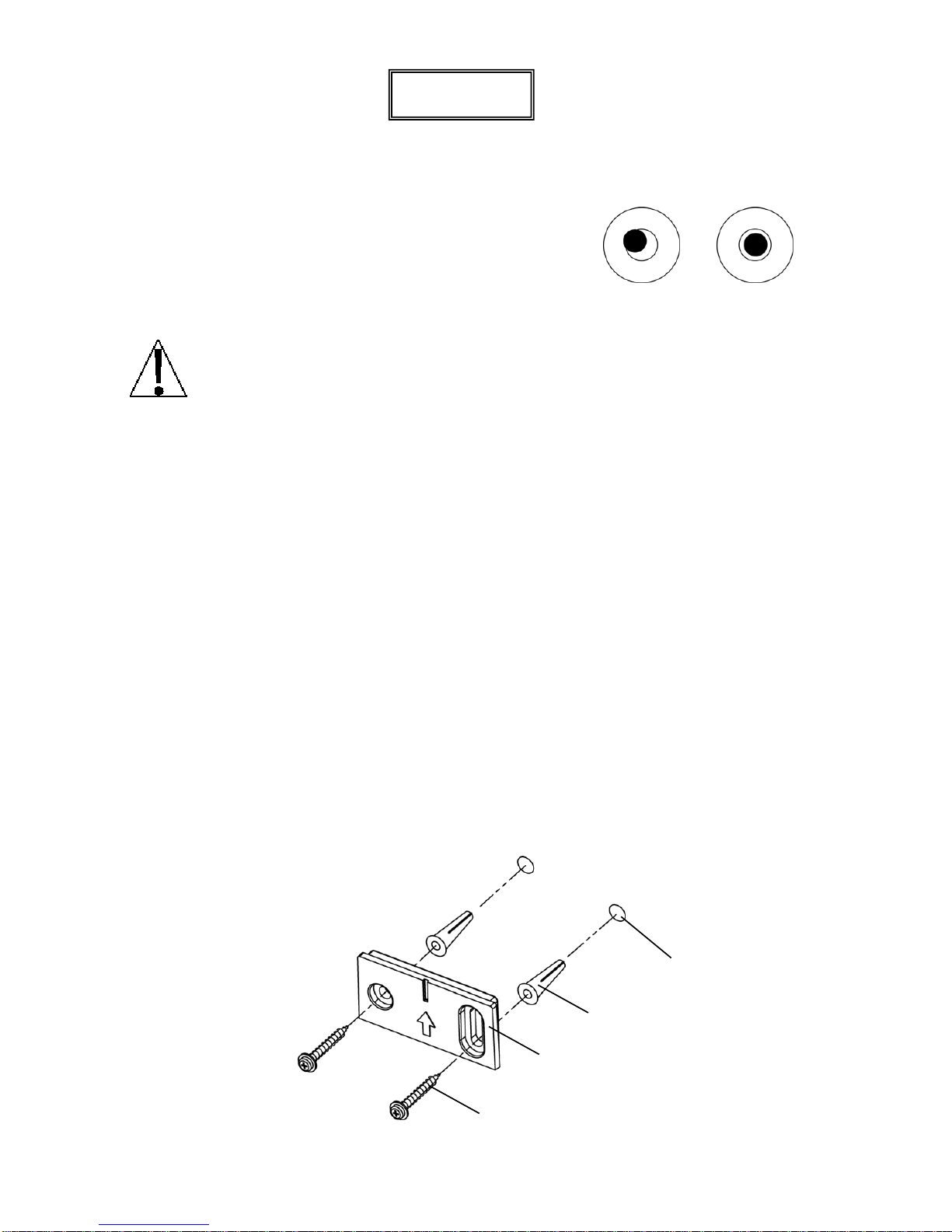
Check to make certain the scale is level. The level indicator is
located at the rear of the scale. If the scale is not level (the bubble
will not be centered), loosen the locking ring on all four (4) feet and
adjust them as required to center the bubble and attain a level
scale. Once the scale is level, lock the feet in place by tightening
the adjustment locking rings against the bottom of the scale.
NOT LEVEL LEVEL
IMPORTANT! Any time a scale is moved or re-located, be sure to check the level
bubble to make sure the scale is level before using.
Placing the Display
The PD100 display has an 87” (220 cm) cable to allow it to be placed at a convenient position
away from the scale base. A bracket is included to mount the display on a wall or the bracket
(and included feet) can used to place it on a desk for easy viewing.
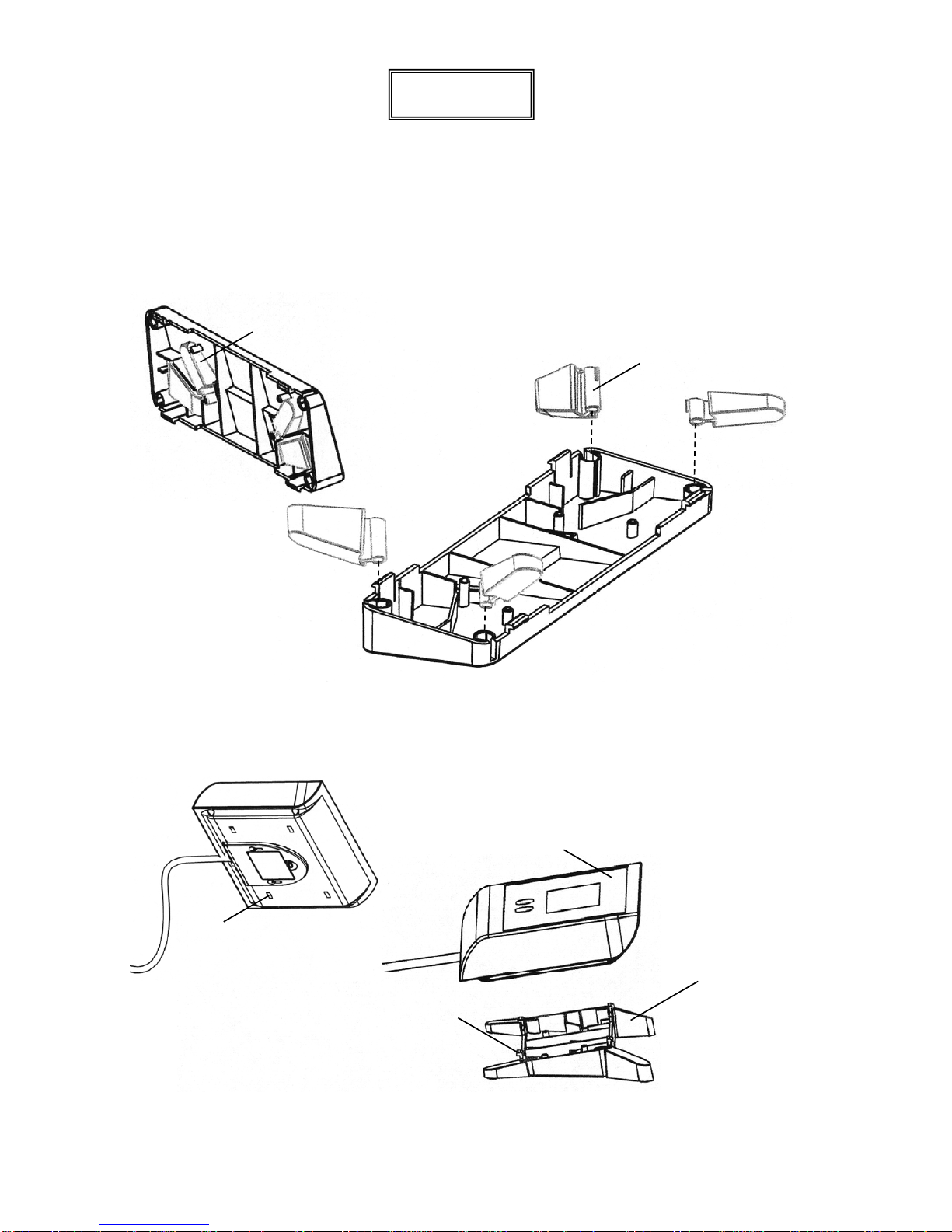
Wall Mounting
1. Choose the location to mount the display on the wall. The location should be free of
temperature extremes and water. It should be where the display can be easily viewed,
not subject to direct sunlight and where the keypad is within easy reach of the operator.
2. Make certain the structure and mounting hardware are of sufficient strength to support the
display. The mounting bracket should be securely fastened to the wall so that it cannot
break loose from the mounting surface.
3. Referring to Figure No. 1 and using Wall Bra cket “B” for a template, place the bracket
against the wall (the notch (arrow) pointing up) and mark the holes to use to mount it.
Remove the bracket and drill two (2) 13/64” (5 mm) holes in the wall for the mounting wall
anchors.
4. Insert the wall anchors in the wall until they are flush with the wall.
5. With the notch (arrow) pointing up on Wall Bracket “B”, insert the two (2) M3.0x25 screws
through the bracket and into the wall anchors.
6. Tighten the screws to secure the bracket to the wall.
M3.0x25 Screw
Plastic Wall Anchor
Wall Bracket “B”
13/64” (5 mm)
Hole in Wall
Figure No. 1
0044-M340-O1 Rev C ProDoc Series
4
PD100
Placing the Display
Wall Mounting, Cont.
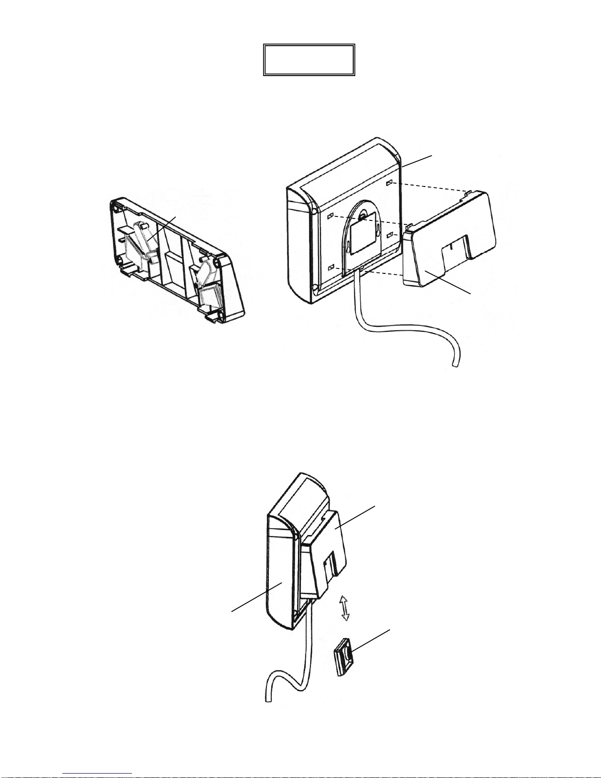
7. Referring to Figure No. 2, make sure the four (4) feet of Wall Bracket “A” are placed in the
bracket.
Feet
(for Desk or
Table Mounting)
Displa
y
Figure No. 2
Figure No. 3
Wall
Bracket
“A”
8. Next, locate the four (4) slots on the back of the display and align them with the four (4)
tabs on the Wall Bracket “A”. Refer to Figure No. 3.
9. Insert the tabs into the slots and press together until the bracket locks to the back of the
display.
10. Referring to Figure No. 4, align the cutout in Wall Bracket “A” with Wall Bracket “B” and
gently pull down to secure the display to the wall.
Display
Wall
Bracket
“A”
Wall
Bracket
“B”
Figure No. 4
0044-M340-O1 Rev C ProDoc Series
5
PD100
Placing the Display
Desk or Table Mounting
1. The location chosen should be a stable, level surface (either a desk or solid table), free of
temperature extremes and water. The display should be where it can be easily viewed,
not subject to direct sunlight and where the keypad is within easy reach of the operator.
2. Referring to Figure No. 5, remove the four (4) feet from inside Wall Bracket “A” and install
them in each corner of the bracket as shown in Figure No. 6.
3. Next, locate the four (4) slots in the back of the display. Refer to Figure No. 7.
4. Referring to Figure No. 8, align and insert the tabs on the bracket with the slots in the
display back and press together until the bracket locks to the back of the display.
Figure No. 5
Figure No. 6
Figure No. 7
Figure No. 8
Remove Feet from
W
all Bracket “A”
Install Feet in
Wall Bracket “A”
Displa
y
Slot
Wall
Bracket “A”
with Feet
Installed
Tab
0044-M340-O1 Rev C ProDoc Series
6
PD200
Unpacking
Remove the scale from the carton by grasping the column (not the display) and lifting up with
equal force on the column and the scale base. After removing from the carton, check for any
damage that may have taken place during shipment. Keep and use the original carton and
packing material for return shipment if it should become necessary. The purchaser is
responsible for filing all claims for any damages or loss incurred during transit. Remove all
plastic wrapping, foam fillers and cardboard material from the scale.
Assembly
The PD200 does not require any assembly.
After installing batteries, the scale is ready for
operation.
Quick Start
Although it is recommended that you read this manual before attempting to operate the scale,
this section is included to provide a condensed set of instructions on installing and using the
scale. At a minimum, please make certain you read all of the caution and warning statements.
Step 1. Place the scale on the floor.
Step 2. Carefully turn the scale over with the display resting on the floor and then locate the
battery access cover on the bottom of the scale.
Step 3. Remove the cover, install six (6) “AA” size batteries1 and then replace the cover.
Step 4. Turn the scale over to the normal operating position and make sure it is level.
Step 5. Press the ON/OFF key to turn the scale on.2
Step 6. When the display is showing 0.0, have to patient step on the scale.
Step 7. Wait a few seconds for the weight to display and then read the patient’s weight.
Step 8. Patient may now step off scale.
Step 9. Press the ON/OFF key to turn the scale off.
1
See page 16 for detailed instructions on installing the batteries.
2
For complete Operation and Setup instructions, refer to pages 18 to 26
0044-M340-O1 Rev C ProDoc Series
7
 Loading...