

Page 1

PORTABLE PLATFORM
SCALES
BEAM TYPE
SERIES 854F/954F
Owner’s Manual
0066-M110-O1 Rev H PO Box 151 y Webb City, MO 64870
09/11 Ph: 417-673-4631 y Fax: 417-673-5001 Printed in USA
Technical Support: Ph: 866-254-8261 y techsupport@cardet.com
CARDINAL SCALE MFG. CO.
www.detectoscale.com
Page 2

Page 3

TABLE OF CONTENTS
SCALE ASSEMBLY DIAGRAM AND INSTRUCTIONS ..................... 2
BASE ASSEMBLY PARTS DIAGRAM AND LIST .............................. 3
COLUMN ASSEMBLY PARTS DIAGRAM ......................................... 4
COLUMN ASSEMBLY PARTS LIST .................................................. 5
BEAM ASSEMBLY PARTS DIAGRAM............................................... 6
BEAM ASSEMBLY PARTS LIST........................................................ 7
854DB DOUBLE BEAM PARTS DIAGRAM....................................... 8
854DB DOUBLE BEAM PARTS LIST ................................................ 9
Thank you for purchasing our Detecto 854F/954F Series Scale. Manufactured with
Detecto quality and reliability at our factory in Webb City, Missouri U.S.A., this scale
has been calibrated and tested before leaving our factory to insure accuracy and
dependability for years to come.
Remove your scale from its packing and inspect it for signs of damage such as
exterior dents and scratches. Keep the carton and packing for return shipment or
relocation if it should become necessary. It is the responsibility of the purchaser to
file all claims for any damage or loss incurred during transit, unless this
responsiblity has been accepted by the Seller in its proposal.
NOTICE
All rights reserved. Reproduction or use, without express permission, of editorial or
pictorial content, in any manner, is prohibited. No patent liability is assumed with
respect to the use of the information contained herein. While every precaution has
been taken in the preparation of this book, the Seller assumes no responsibility for
errors or omissions. Neither is any liability assumed for damages resulting from the
use of the information contained herein. All instructions and diagrams have been
checked for accuracy and ease of application; however, success and safety in
working with tools depend to a great extent upon the individual accuracy, skill and
caution. For this reason the Seller is not able to guarantee the result of any
procedure contained herein. Nor can they assume responsibility for any damage to
property or injury to persons occasioned from the procedures. Persons engaging
the procedures do so entirely at their own risk.
1
Page 4
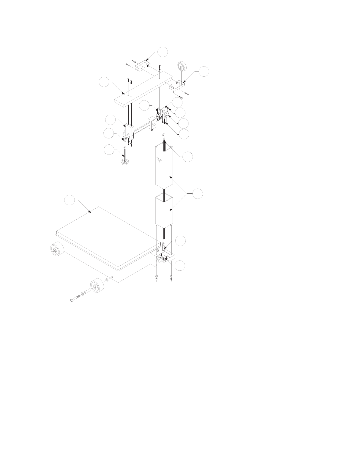
SCALE ASSEMBLY INSTRUCTIONS
Refer to Figure Number 1 and follow the instructions below for scale assembly.
H
G
L
K
Figure Number 1
SCALE ASSEMBLY
DIAGRAM
A
J
E
D2
D1
D
F
C
B
C1
1. Assemble wheels to scale base
with four 5/8-11 x 3 1/2" hex head
bolts, four sleeves and eight 5/8 flat
washers. To secure the wheel,
J
tighten the bolt against the sleeve
to the scale base.
2. Insert column (B) into scale
base assembly (A) and secure with
two 3/8 split lock washers and two
3/8 -16 hex nuts. NOTE: Detecto
decal should be facing toward the
platform.
3. Lower steelyard rod assembly
(C) into column (B).
4. Hook hanger bearing (C1) into
pivot (A1).
5. Column cap (H) may now be
placed over column (B) together
with weight racks (J). NOTE: If
using only one weight rack, we
recommend it be assembled to the
back of the column. Secure with
four 1/4 - 20 x 3/4" hex head bolts
and four 1/4 split lock washers.
6. Attach trig loop (G) to column
A1
8. Attach steelyard rod (C) onto the load loop assembly (F).
9. Secure the fulcrum loop assembly (E) to the column cap (H) with one 1/4-20 x 1" hex head
bolt, one 1/4 split lock washer and one 1/4 flat washer.
10. Hook counterpoise (K) into beam loop assembly (L). Scale assembly is now complete.
FINAL SEALING AND ADJUSTING INSTRUCTIONS
1. Place capacity poise at Zero, move balance ball (D2) to center of adjusting area by turning
zero adjust screw (D1).
2. Remove screw from counterpoise cup (K). Remove sufficient shot from cup (K) until scale is in
balance. NOTE: Screw must be used as part of weight when removing shot.
3. Replace and tighten screw into counterpoise cup (K). NOTE: Beam must arc freely, otherwise,
all bearings and hook connections must be rechecked for proper assembly. Scale is now ready for
operation. (Note: Scale must be set up and operation must be on a level surface. The scale is level
when the air bubble is in the target on the bulls-eye level.)
cap (H) with two 1/4 - 20 x 3/4"
carriage bolts, two 1/4 split lock
washers and two 1/4 - 20 hex nuts.
7. Guide beam assembly (D)
through the trig loop (G) and back
into the column (B) opening.
2
Page 5
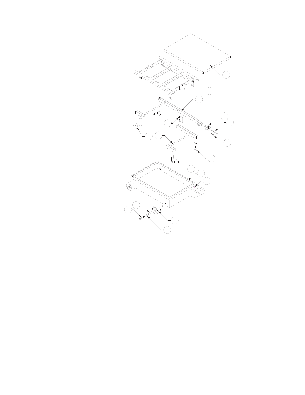
Figure Number 2
BASE ASSEMBLY
PARTS DIAGRAM
BASE ASSEMBLY
8
6
7
4
1
2
3
9
11
10
5
8
12
17
15
14
13
16
Item No. 854F Part No. 954F Part No. Part Name Quantity
1 0066-C017-08 0066-D057-0A Deck Plate 1
2 0066-D012-0A 0066-D107-0A Weighbridge Assembly 1
3 0066-D006-0A 0066-D060-0A Long Lever Assembly 1
4 0066-D007-0A 0066-D061-0A Short Lever Assembly 1
5 0066-B004-0A 0066-B004-0A Long Hanger Assembly 2
6 0066-B005-0A 0066-B005-0A Short Hanger Assembly 2
7 0066-B008-0A 0066-B008-0A Center Hanger Assembly 1
8 0066-B003-08 0066-B003-08 Bearing 4
9 0066-B010-0A 0066-B010-0A Nose Iron Assembly 1
10 6021-1458 6021-1458 5/16 -18UNC x 1 3/4" Hex head Bolt 1
11 6021-1833 6021-1833 5/16 -18UNC x 4" Hex head Bolt 1
12 0066-D002-0A 0066-D067-0A Base Weldment 1
13 0066-B199-08 0066-B199-08 5" Rubber Wheel 4
14 6007-0240 6007-0240 5/8 -11 x 3 1/2" Hex head Bolt 4
15 0066-B200-08 0066-B200-0A Sleeve 4
16 6024-0015 6024-0015 5/8 Flat Washer 8
17 6690-0001 6690-0001 Bulls-eye Level 1
3
Page 6

27
28
35
36
34
29
28
21
25
26
31
30
24
28
32
Figure Number 3
COLUMN ASSEMBLY PARTS DIAGRAM
37
22
23
33
4
Page 7

COLUMN ASSEMBLY
Item No. Part No. Part Name Quantity Model No.
21 0066-C036-18 Column Cap 1 854F/954F
22 0066-C042-0A Column Assembly 1 854F/954F
23 6P33X Steelyard Rod Assembly 1 854F/954F
24 6P2009X Trig Loop 1 854F/954F
25 345MV0406 1/4 - 20 X 3/4" Carriage Bolt 2 854F/954F
26 6013-0045 1/4 - 20 Hex Nut 2 854F/954F
27 6021-1454 1/4 - 20 x 3/4" Hex Head Bolt 4 854F/954F
28 6024-0039 1/4 Split Lock Washer 7 854F/954F
29 6021-1428 1/4-20 x 1" Hex Head Bolt 1 854F/954F
30 6024-0003 1/4 Flat Washer 1 854F/954F
31 6P1007 Weight Rack 1 or 2 854F/954F
as required
32 6024-0045 3/8 Split Lock Washer 2 854F/954F
33 6P23 3/8 - 16 Hex Nut 2 854F/954F
34 593M729 Serial No. Plate 1 854F/954F
35 6680-0073 Pop Rivet 2 854F/954F
36 6PSS1002 Detecto Logo Decal 1 854F/954F
37 6PP3000X Weight Pack Assembly 1000lb 1 854F100P
6PP3050X Weight Pack Assembly 500lb 1 854F50P
6PK2500X Weight Pack Assembly 500kg 1 854F50K
6PK2550X Weight Pack Assembly 1000lb/500kg 1 854F100PK
6PL1000X Weight Pack Assembly 1000 libra/500kg 1 854FFS
6PK10 Weight 1
0066-C241-1A Weight 1
6PK20 Weight 1
0066-C239-1A Weight 1 854F-50PK
0066-C234-1A Weight 1
0066-C236-1A Weight 1
0066-C233-1A Weight 1
0066-C234-1A Weight 1
0066-C236-1A Weight 2 954F100P
0066-C237-1A Weight 3
0066-C239-1A Weight 1
0066-C241-1A Weight 1 954F50K
0066-C242-1A Weight 4
0066-C239-1A Weight 1
0066-C241-1A Weight 1
0066-C242-1A Weight 4 954FFS
0066-C234-1A Weight 1
0066-C236-1A Weight 2
0066-C237-1A Weight 3
}
}
2000 lb
1000 lb
}
1000 kg
}
500 lb/
200 kg
2000 libra
2000 libra/
1000 kg
5
Page 8

65
58
59
57
53
55
56
67
51
60
61
54
60
52
62
63
54
66
64
Figure Number 4
BEAM ASSEMBLY PARTS DIAGRAM
6
Page 9

BEAM ASSEMBLY
Item No. 854F Part No. 954F Part No. Part Name Quantity Model No.
51 6P10037 6P10037 Beam 1
52 & 53 6P11037 6P11037 Insert 100lb (Rear) 1 854F100P/954F100P
6P11137 6P11137 Insert 100lb (Front) 1 854F100P/954F100P
6P11042 Insert 50lb (Rear) 1 854F50P
6P11142 Insert 50lb (Front) 1 854F50P
6P11038 6P11038 Insert 50kg (Rear) 1 854F50K/954F50K
6P11138 6P11138 Insert 50kg (Front) 1 854F50K/954F50K
6P11044 Insert 20kg (Rear) 1 854F50PK
6P11142 Insert 50lb (Front) 1 854F50PK
6P11043 Insert 100lb (Rear) 1 854F100PK
6P11138 Insert 50kg (Front) 1 854F100PK
6P11039 6P11039 Insert 100 libra (Rear) 1 854FFS/954FFS
6P11138 6P11138 Insert 50kg (Front) 1 854FFS/954FFS
54 0066-B040-08 0066-B040-08 Pivot 3
55 0066-D112-0A 0066-D112-0A Poise Assembly 1 854F100P/954F100P
6P1031X 6P1031X Poise Assembly 1 854F50P
854F50PK
0066-D112-3A 0066-D112-3A Poise Assembly 1 854F50K/954F50K
854F100PK
854FFS/954FFS
56 2P60 2P60 Adjusting Spring 1
57 6029-0032 6029-0032 Snap Ring 1
58 6P27 6P27 Balance Weight 1
59 6P22 6P22 Adjusting Screw 1
60 6029-0022 6029-0022 Snap Ring 2
61 6P72 6P72 Pin 1
62 6P74 6P74 Pin 1
63 0066-C041-1A 0066-C041-1A Beam Loop Assem. 1
64 6P10021X 0066-B109-0A Counter Poise Assem. 1
65 0066-B126-1A 0066-B126-1A Fulcrum Loop Assem. 1
66 0066-B125-0A 0066-B125-0A Load Loop Assem. 1
67 6024-1043 6024-1043 Washer Nylon 1
7
Page 10

854DB DOUBLE BEAM SCALE
DOUBLE BEAM ASSEMBLY PARTS DIAGRAM
Figure Number 5
8
Page 11

854DB DOUBLE BEAM SCALE
(Assembly for avoirdupois, unit available in metric)
Only 1700 Demountable Heads can be used with these scales.
ITEM PART PART NAME QUANTITY
NUMBER NUMBER
1 6P7037X Beam W/Pivots 1
2 6P6042 Tare Beam 1
3 6P11138 Insert 50K Front 2
4 6P11038 Insert 50K Rear 2
5 6P11137 Insert 100P Front 2
6 6P11037 Insert 100P Rear 2
7 6P11142 Insert 50P Front 2
8 6P11042 Insert 50P Rear 2
9 6P10021X C-Poise Assy. 1
10 0066-B109-0A C-Poise Assy. 1
11 0066-C041-1A Beam Loop Assy. 1
12 0066-B125-0A Load Loop Assy. 1
13 0066-B126-1A Fulcrum Loop Assy. 1
14 6P166X Balance Wt. Assy. 1
15 6560-1061 Loctite #262 or Equal A/R
16 6P22 Adjusting Screw 1
17 6P27 Balance Weight 1
18 6029-0022 E-Ring 3/8” 2
19 6029-0032 E-Ring 5/16” 1
20 6P167 Spacer 1
21 548R590810 Roll Pin 4
22 6013-0295 Nut Hex #10-32 4
23 6021-1001 Scw Rd Head #10-32 4
24 6024-1010 Washer Lock #10 4
25 6021-1454 Scw Hex Hd 1/4-20 2
26 6024-0039 Washer Lock 1/4 2
27 6024-1043 Washer Flat 5/16 1
28 6007-0011 Blt Hex Head 1/4-20 1
29 6024-0003 Washer Flat 1/4 1
30 2P60 Spring 1
31 6P1065 Poise Screw REF
32 6P65X Poise Screw Assy REF
33 6P5042X Beam W/Pivots 1
34 0066-D112-0A Poise Assy (Uses Item 32) 2
35 6P1031X Poise Assy Alum (Uses Item 31) 1
36 0066-D112-3A Poise Assy (Uses Item 32) 1
9
Page 12

STATEMENT OF LIMITED WARRANTY
j
Detecto Scale warrants its equipment to be free from defects in
material and workmanship as follows: Detecto warrants to the
original purchaser only that it will repair or replace any part of
equipment which is defective in material or workmanship for a
period of one (1) year from date of shipment. Detecto shall be the
sole judge of what constitutes a defect.
During the first ninety (90) days Detecto may choose to supply all
necessary replacement parts and service during normal weekday
working hours at no charge to the buyer.
After the first ninety (90) days Detecto will supply parts and
service at the job site provided the owner agrees to pay the Dealer
for all travel time, including mileage and test equipment, as well as
any expenses incurred over the direct labor of the technician at the
ob site. This limited warranty honors only labor performed by
Detecto authorized dealers.
This warranty does not apply to peripheral equipment not
manufactured by Detecto; this equipment will be covered by certain
manufacturer’s warranty only.
This warranty does not include replacement of expendable or
consumable parts. This does not apply to any item which has
deteriorated or damaged due to wear, accident, misuse, abuse,
improper line voltage, overloading, theft, lightning, fire, water or acts
of God, or due to extended storage or exposure while in purchaser’s
possession. This warranty does not apply to maintenance service.
Purchased parts will have a ninety (90) day repair or replacement
warranty only.
Detecto may require components be returned to the factory; they
must be properly packed and shipping charges prepaid. A return
authorization number must be obtained for all returns and marked
on the outside of all returned packages. Detecto accepts no
responsibility for loss or damage in transit.
Page 13

STATEMENT OF LIMITED WARRANTY
g
Conditions Which Void Limited Warranty
This warranty shall not apply to equipment which:
A.) Has been tampered with, defaced, mishandled or have had
repairs and modifications not authorized by Detecto.
B.) Has had serial number altered, defaced, or removed.
C.) Has not been grounded according to Detecto’s recommended
procedure.
Freight Carrier Damage
Claims for equipment damaged in transit must be referred to the
freight carrier in accordance with freight carrier regulations.
This warranty sets forth the extent of our liability for breach of any
warranty or deficiency in connection with the sale or use of the
product. Detecto will not be liable for consequential damages of any
nature, includin
whether based on tort or contract. Detecto reserves the right to
incorporate improvements in material and design without notice and
is not obligated to incorporate improvements in equipment
previously manufactured.
The foregoing is in lieu of all other warranties, express or implied
including any warranty that extends beyond the description of the
product including any warranty of merchantability or fitness for a
particular purpose. This warranty covers only those Detecto
products installed in the forty-eight (48) contiguous continental
United States.
but not limited to, loss of profit, delays or expenses,
Ph. (800) 641-2008
E-mail: detecto@cardet.com
203 E. Daugherty
Webb City, MO 64870
D268-WARRANTY-DET
02/06
Printed in USA
Page 14

2
Page 15

2
Page 16

 Loading...