

Page 1

Cardinal®
CN20 Series
Weight Indicating
Instruments
Technical Manual
8534-M514-O1 Rev B
5/98
Cardinal Scale Mfg. Co.
PO BOX 151 • WEBB CITY, MO 64870
417-673-4631 Fax: 417-673-5001
Printed in USA
Page 2

2
Page 3
CN20 Digital Weight
TABLE OF CONTENTS
Indicating Instrument
Congratulations on your purchase of a series
CN20 Digital Weight Indicating Instrument. This
instrument, which has been designed and
manufactured in the U.S.A., incorporates the
latest digital technology and includes features
that were unavailable only a shor t time ago. With
reasonable care your CN20 should provide years
of accurate weight measurements.
The series CN20 is housed in an
injection-molded polycarbonate enclosure and
may be mounted on a scale column or on a wall
or desktop. The instrument is available with
either a red LED display or a high-contrast LCD
display. Although the basic weight indicating
instrument is designed to operate from batteries,
optional plug-in power supplies are available for
115 VAC or 230 VAC.
SPECIFICATIONS .......................................1
INSTALLATION ............................................1
Power Supply .....................................2
Batteries .............................................2
Load Cell Connection.........................3
SETUP AND CALIBRATION........................3
FINE SPAN ..................................................8
KEYPAD FUNCTIONS.................................8
ANNUNCIATORS.........................................9
SETUP REVIEW..........................................10
BATTERY CHARGING.................................11
PRINTED CIRCUIT BOARD
JUMPER TABLE ..........................................11
ERROR & STATUS DISPLAY ......................11
CARE AND CLEANING ...............................12
BEFORE YOU CALL FOR
SERVICE ...................................................12
APPENDIX A
Replacement Part ID List ...................13
The CN20 keyboard allows the operator to lock
the weight display as well as review and change
operational parameters including sample rate,
filtering, auto shutoff and sleep mode.
This manual is provided to serve as your guide to
the installation, operation and maintenance of
your new weight indicating instrument. Please
take the time to read this manual before
attempting to install or operate your CN20.
FCC COMPLIANCE STATEMENT
WARNING! This equipment generates, uses and
can radiate radio frequency energy and if not
installed and used in accordance with the
instructions in this manual, may cause
interference to radio communications. It has been
tested and found to comply with the limits for a
Class A computing device pursuant to Subpart J
of Part 15 of FCC Rules, which are designed to
provide reasonable protection against such
interference when operated in a commercial
environment. Operation of this equipment in a
residential area is likely to cause interference in
which case the user, at his own expense, will be
required to take whatever measures may be
required to correct the interference.
All rights reserved. Reproduction or use, without express
permission, of editorial or pictorial content, in any manner,
is prohibited. No patent liability is assumed with respect to
the use of the information contained herein. While every
precaution has been taken in the preparation of this book,
we assume no responsibility for errors or omissions.
Neither is any liability assumed for damages resulting from
the use of the information contained herein. All instructions
and diagrams have been checked for accuracy and ease
of application; however, success and safety in working
with tools depend to a great extent upon the individual
accuracy, skill and caution. For this reason, we are not
able to guarantee the result of any procedure contained
herein. Nor can we assume responsibility for damage to
property or injury to persons occasioned from the
procedures. Persons engaging the procedures do so
entirely at their own risk.
PRECAUTIONS
Before using this instrument, read this
manual and pay special attention to all
“WARNING” symbols:
IMPORTANT ELECTRICAL
WARNING
SERIAL NUMBER
You may find the booklet “How to Identify and
Resolve Radio TV Interference Problems” prepared
by the Federal Communications Commission helpful.
It is available from the U.S. Government Printing
Office, Washington, D.C. 20402. Stock No.
001-000-00315-4.
DATE OF PURCHASE
PURCHASED FROM
RETAIN THIS INFORMATION FOR FUTURE USE
Page 4

2
Page 5

SPECIFICATIONS
Power Requirements: 12 VDC, 300ma Optional Power Supply
Operating Temperature: 14°F (-10°C) to 104°F (40°C)
Display: 4 ea. 0.7" 7-Segment High-Contrast LCD (CN20L)
or: 0.56" 7-Segment Red LED (CN20E)
Sensitivity: 1.5 uV/Graduation (0 - 3 mV/V input)
Load Cell Excitation: 5.0 VDC
Maximum Load Cell Cable Length: 30'
Capacities: 1,000 - 9,999 Displayed Graduations
Resolution: 1 part in 9,999 Displayed
1 part in 40,000 Internal
Graduation Value: 1, 2 or 5 x 1, .1, .01, .001
Sample Rate: 1 - 12 Samples Per Second Selectable
Auto Zero Range: 0.5, 1 or 3 Graduations
Manual Zero Range: 4% Capacity or Full Capacity
Weight: (Without Batteries) 1.3 lb (.06 kg)
(With Batteries) 3.2 lb (1.5 kg)
Dimensions: 9 1/8" W x 5" H x 3" D
Sleep Mode: Selectable power save mode with automatic activation from 1
- 9 minutes if at zero without motion.
Options: AC Plug-in Power Modules for Operation from either 115
VAC or 230 VAC
Full Numeric Keypad (CN20LT)
Specifications subject to change without notice.
INSTALLATION
Before beginning installation of your CN20 weight indicator, make certain that the instrument has
been received in good condition. Carefully remove the instrument from the shipping carton and
inspect it for any evidence of damage that may have taken place during shipment. Should your CN20
come already installed on a scale, the following information describing the installation of the
instrument does not apply to you.
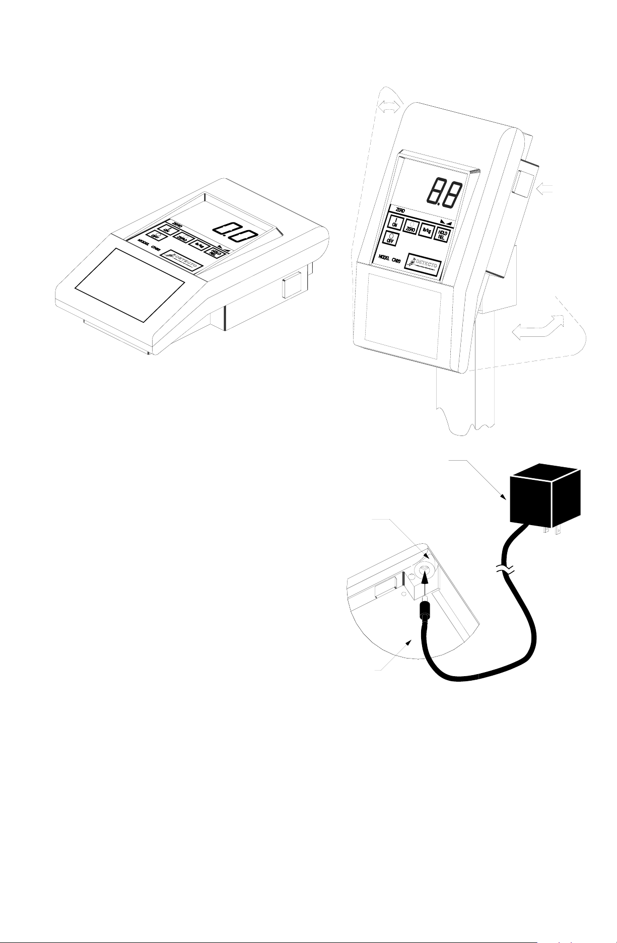
Begin the installation by deciding where the instrument is to be mounted. The CN20 may come
mounted on a column or you may choose to mount it on a desktop or wall. Refer to Figure no. 1 for
illustrations of these various mounting arrangements. Note: If you use the mounting bracket on the
scale column you may select any of these variations. Two (2) holes are located in the mounting
bracket for attachment to the wall or column top. This bracket may be removed or left in place for
desktop use. To remove the bracket, pry outward on the bracket at each of the pivot points while
pressing the tilt buttons and pulling downward on the bracket.
1
Page 6
INSTALLATION, Cont.
Regardless of how you mount your CN20, it should be in a safe area where it will not be in the way of
normal traffic. The mounting bracket should be
securely fastened to the wall or column top so that it
cannot break loose from the mounting surface. After
the CN20 has been mounted, it may be connected to
the optional plug-in power supply or the batteries may
be installed.
Tilt
Desk Top
Figure No. 1
OPTIONAL PLUG-IN POWER SUPPLY
If you have ordered an optional plug-in power supply to
operate your CN20 from a wall outlet it may be
installed at this time. Remove the power supply
from the shipping carton and insert the output
power cable connector into the power jack
located on the underside of the CN20 enclosure.
Refer to Figure no. 2 for the location of the power
jack. Insert the power supply connector into the
wall outlet.
Press here
on both sides
to tilt
May be
rotated
Column Mount
Optional AC Power
Supply - 115 VAC
or 230 VAC Model
Power Jack
BATTERIES
If you did not order an optional plug-in power
supply or if you did but wish to operate the CN20
from batteries, you must install batteries before
operations can begin. The CN20 uses six (6) “D”
size Alkaline or Ni-Cad batteries. These batteries
are contained in a slide-out drawer at the back of
the instrument enclosure.
To remove the battery drawer, press down on the
release pad while pulling outward. Remove the
Bottom of
Instrument
battery drawer from the instrument. Install six (6)
“D” size batteries in the drawer making certain
Figure No. 2
that they are positioned in accordance with the
battery outline located in the bottom of the
drawer. Note: All six (6) batteries must be of the same type. They must all be Alkaline or they must all
be Ni-Cad. DO NOT mix Alkaline and Ni-Cad batteries. Refer to Figure no. 3 for illustration of battery
installation.
After placing all six (6) of the batteries in the drawer, replace the drawer in the CN20 and push it all
the way forward until the retaining latch snaps into place. Failure to push the drawer in until the latch
engages will keep the instrument from operating. Press the ON key. If the display turns on and the
BAT annunciator is off, the batteries have been installed correctly. If not, remove the tray and check
for one (1) or more improperly positioned batteries.
2
Page 7

INSTALLATION, Cont.
Alkaline batteries will last several months in an instrument with a LCD display. They will last only a
couple of days in an instrument with a LED display. Therefore, it is recommended that rechargeable
Ni-Cad batteries be used in instruments with LED displays.
The battery charging circuitry is disabled. Should you wish to enable or disable your battery charger,
please contact your scale serviceman.
Figure No. 3
Press
Pull
Remove Battery Drawer Install Batteries as Shown
LOAD CELL CONNECTIONS
The load cell connection to the CN20 is made
via a 6-PIN modular type connector located on
Scale
Input
(See Detail)
Figure No. 4
the rear panel of the enclosure. Refer to Figure
no. 4 for the location of this connector. Your
scale should be equipped with a cable
terminated in a modular type connector. This
connector should be inserted into the mating
connector on the rear of the CN20 until it locks
into place.
If you are connecting the CN20 to a scale without a modular connector, it will be necessary to modify
the scale cable by installing a 6-conductor modular connector. Refer to the detail figure and table
below for identification of the wires from this connector.
Load Cell Connector Wiring
PIN # SIGNAL WIRE COLOR
1 2 3 4 5 6
1 N.C.
2 N.C.
3 +EXC GREEN
4 +SIG RED
5 -EXC BLACK
6 -SIG WHITE
N.C. = no connection
*Blue and Yellow wire not used
BLUE*
YELLOW*
SETUP AND CALIBRA TION
If you received your CN20 already installed on a scale, calibration is not required. Your
scale was calibrated at the factory.
Before beginning the setup and calibration of your CN20, first make certain that it has been installed
in accordance with the instructions given in this manual. Remove the two (2) front screws from the
bottom of the enclosure and loosen the rear two (2). Make certain the CN20 has been turned off then
lift upward on the rear of the top enclosure to expose the calibration switch. Refer to Figure no. 5 for
the identification and location of this switch.
Press the calibration switch and hold it while pressing the ON key on the instrument’s keyboard.
Release the calibration switch. If the display shows int= the CN20 is ready for setup and
calibration. If, however, the display is blank the following should be checked:
1. If using the optional AC plug-in power supply, verify that the mating connector is fully seated in
the power jack on the bottom of the instrument housing and that the power supply is plugged
into a working outlet.
3
Page 8

SETUP AND CALIBRATION, Cont.
2. If operating from batteries,
Printed Circuit Board
Loosen
Figure No. 5
Calibration
Switch
Push and hold
during power up
Remove
and the CN20 will advance to the next prompt. The cursor location is identified by the blinking
character and can be advanced to the left to the next position by pressing the lb/kg key. Pressing the
ZERO key will change the blinking character to the next value.
verify that the batteries are new or
if Ni-Cad, that they are fully
charged and that they have been
correctly installed in the battery
drawer. Make certain that the
battery drawer is fully inserted and
that the drawer catch is engaged.
3. Make certain that the
calibration switch is fully depressed
when the ON key is pressed. Press
the OFF key and repeat the
procedure.
After the int= display prompt is
shown in the CN20 display window,
setup and calibration may continue.
During the setup and calibration
process it will be necessary to
enter operational parameters via
the CN20’s keyboard. Pressing the
HOLD/REL key will cause the data
entered or displayed to be retained
NOTE: IF YOUR INDICATOR IS EQUIPPED WITH A NUMERIC KEYPAD below the upper keypad, the
function of the HOLD/REL key during setup and calibration is replaced by the ENTER key. The
functions of lb/kg and ZERO keys during setup and calibration are replaced by the numeric keys. If a
YES or NO response is required, pressing the 1 key will display YES, the 0 key will display NO.
SCALE INTERVAL
With the display showing int= press the HOLD/REL key, then the ZERO key until the proper scale
interval (1, 2 or 5) is displayed, then press the HOLD/REL key to store the displayed value and
proceed to the next prompt.
DECIMAL POINT LOCATION
With the display showing dP= press the HOLD/REL key then the ZERO key until the number of digits
to the right of the decimal point is displayed, then press the HOLD/REL key to store this setting and
proceed to the next step. Numbers zero (0) through three (3) are available and correspond to the
following decimal point locations:
0 = XXXX 2 = XX.XX
1 = XXX.X 3 = X.XXX
SCALE CAPACITY
With the display showing CAP= press the HOLD/REL key, then use the ZERO key to enter the
proper digit at the blinking location, then press the lb/kg key to step to the left and the next digit
location. Repeat the process until all four (4) digits of the scale’s capacity have been entered. Should
you make a mistake and press the lb/kg key with an incorrect digit entered, it will be necessary to
repeatedly press the lb/kg key until the blinking character returns to the proper location, then use the
ZERO key to enter the correct digit. After all four (4) digits have been correctly entered, press the
HOLD/REL key to store the capacity and advance to the next step.
WEIGHING UNITS
With the display showing Unt= press the HOLD/REL key to show current setting, then press ZERO
to select 1 through 6. Press the HOLD/REL key to save setting.
1=Pounds Only 3=Pounds/Kilograms 5=Ounces Only
2=Kilograms Only 4=Kilograms/Pounds 6=Grams Only
4
Page 9

SETUP AND CALIBRATION, Cont.
LOAD CALIBRATION WEIGHT
The display will now indicate Lod= which is a prompt for the entry of the calibration weight value and
placement of this amount of test weights on the scale platform. If the scale has been previously
calibrated and you do not wish to change the calibration setting, simply press the HOLD/REL key
twice without taking any other action and the internal calibration factor will be retained. If, however,
the scale needs to be calibrated, press the HOLD/REL key once and proceed in the following
manner:
1. Place the desired amount of calibrated test weights on the scale platform. It is recommended
that a minimum of 50% of the scale’s capacity be used but 70% to 100% is preferred.
2. Determine the exact amount of test weights to be placed on the scale platform and enter this
value into the CN20 by using the ZERO and lb/kg keys in the same manner used to enter the
scale’s capacity. Verify that the numbers entered are the same as the total weight of test
weights, and the least significant digit agrees with the scale interval.
3. Press the HOLD/REL key.
After a moment the display will indicate the message UnLd which is a request that the calibrated test
weights be removed from the scale platform. Remove all of the weights then press the HOLD/REL
key. The calculated calibration factor is now stored in the CN20’s nonvolatile memory.
ZERO TRACKING RANGE
The CN20 display will now indicate trA=. Press the HOLD/REL key to show the value assigned to
the Automatic Zero Tracking range. This is the value in scale divisions that will be automatically
zeroed off. That is, if the scale divisions are 0.5 and the zero tracking is set to 3, the CN20 will
automatically zero weights of 1.5. Values of zero (0) through nine (9) divisions and 0.5 division are
available for the zero tracking range. Use the ZERO key to step through these available values. Once
the proper value is shown, press the HOLD/REL key to store the value.
FOUR PERCENT ZERO TRACKING RANGE
The display will next indicate trL= which is the prompt requesting whether a 4% limit be placed on
the Automatic Zero Tracking feature. This 4% limit is a requirement by Canadian Weights and
Measures but, at the time this was printed, is not a U.S. requirement. Press the HOLD/REL key, then
use the ZERO key to enter either YES, (use the 4% limit) or NO, (do not use the 4% limit) and press
the HOLD/REL key.
POWER UP ZERO
With the display showing PU0= press the HOLD/REL key to show current setting, then press ZERO
to select YES (enable) or NO (disable). Press HOLD/REL key to save setting.
DIGITAL FILTER LEVEL SELECTION
The display will now show FLt= which is the prompt for the selection of the digital filtering level. Four
(4) levels of filtering (0, 1, 2 and 3) are available with zero (0) having minimum filtering and two (2) the
greatest. Three (3) is used for custom filtering when zero (0), one (1) or two (2) are inadequate. Press
the HOLD/REL key, then use the ZERO key to select the desired level of filtering then press the
HOLD/REL key to save the setting. If you select level three (3) for custom filtering, the CN20 will
respond with F= which is the filter weight setting. Use the ZERO and lb/kg keys to select from 1 to 16
filter weight levels then press HOLD/REL to save the setting. The CN20 will respond with br= which
is the break point setting. Using the ZERO key select from 1 to 64 divisions as the break point value
then press the HOLD/REL key to save the setting. Your CN20 should arrive from the factory with the
proper filter setting already entered. Please check with your scale service technician should you wish
to change the programmed filter weight and break point.
MOTION (UNSTABLE) RANGE
The display will next indicate UnS= which is the prompt for the motion (unstable) range. Changes in
weight exceeding the selected number of divisions will cause the stable indicator to turn off. Values
from zero (0) to nine (9) divisions may be selected after pressing the HOLD/REL key by pressing the
ZERO key. Once the correct value is shown press the HOLD/REL key to save the setting.
SAMPLE RATE
The display will now indicate Sr= which is the prompt for entry of the sample rate. The sample rate
may be set from a minimum of one (1) sample per second to a maximum of twelve (12) samples per
second in one (1) sample per second intervals. After pressing the HOLD/REL key use the ZERO and
5
Page 10

SETUP AND CALIBRATION, Cont.
SAMPLE RATE, Cont.
lb/kg keys until the desired sample rate is displayed then press the HOLD/REL key to save the
setting. Note: Like the filtering level, the sample rate may be changed later without having to enter
the calibration mode.
AUTOMATIC SHUTOFF
The display will now indicate ASH= which is the prompt for the selection of the Automatic Shutoff
feature. This feature will automatically turn the CN20 off after a predetermined period of inactivity. To
turn the instrument back on you must press the ON key. This feature helps prolong battery life by
turning the CN20 off when it is not in use. After pressing the HOLD/REL key, use the ZERO key to
select the desired number of minutes (1 through 9) of inactivity before turning the CN20 off. Entry of
the number zero (0) disables the Automatic Shutoff feature. Press the HOLD/REL key to save the
setting. Note: This setting may be revised without having to enter the calibration mode.
SLEEP MODE
The display will now indicate SLP= which is the prompt for selection of the Sleep feature which can
also be used to conserve battery power when the indicator remains unused for a selected period of
time. If this feature is enabled, the load cell excitation will be reduced and the display will be reduced
to one scrolling segment after remaining at zero for the selected time from 1-9 minutes. Unlike the
Automatic Shutoff feature which only requires that there be no motion on the indicator to activate, the
Sleep feature requires that the indicator remain at zero (0) to activate. To enable the Sleep feature
after pressing the HOLD/REL key, use the ZERO key to display a number of 1 to 9 which
corresponds to number of minutes of inactivity while at zero (0) before the indicator will automatically
enter the Sleep mode. Press HOLD/REL to store the setting. Entry of zero (0) turns this feature off.
PUSH BUTTON TARE
With the display showing Pbt= press the HOLD/REL key to show current setting, then press ZERO
to select YES (enable) or NO (disable). Must be NO if equipped with standard (Figure no. 7) keypad.
Press the HOLD/REL key to save setting.
AUTOMATIC HOLD MODE
The display will next indicate HLd= which is the prompt for the selection of the Automatic Hold mode.
This mode of operation is used to lock the CN20 display and is used only in noncommercial
applications. After pressing the HOLD/REL key, enter a YES to enable or a NO to disable by pressing
the ZERO key, then press the HOLD/REL key. This feature must be set to NO for “Legal for Trade”
applications.
NON-ROLL-UP MODE
The CN20 display will now indicate nrU= which is the prompt for selection of the Non-Roll-Up mode
of operation. The Non-Roll-Up mode blanks the display and delays the weight display update until the
weight has stabilized or a three-second time delay has elapsed. A single moving segment is displayed
during this time delay. After pressing the HOLD/REL key, press the ZERO key to set the value to YES
or NO, then the HOLD/REL key to save the setting.
INHIBIT SERIAL DATA
The display will now indicate iSnd=. After pressing the HOLD/REL key, press the ZERO key to set
the value to NO. Press the HOLD/REL key to save the setting.
The display will display the software revision number then the gross weight. The setup and calibration
process has been completed and the indicator is ready to weigh. Place the test weight back on the
scale to verify calibration.
Make certain that all four (4) screws in the bottom of the CN20 enclosure have been tightened.
A summary of the setup and calibration steps is shown in Figure no. 6 to serve as a quick reference.
6
Page 11

SETUP AND CALIBRATION, Cont.
1. Press OFF key.
2. Press and hold calibration switch.
3. Press ON key.
int=
dP=
0=XXXX
1=XXX.X
CAP=
Interval
1, 2 or 5
Decimal Point
Location
0, 1, 2 or 3
2=XX.XX
3=X.XXX
Scale
Capacity
up to 9,999
FLt=
0=No Filtering
1=Minimal Filtering
F=
0, 1, 2 or 3
If 0, 1 or 2 then
If 3 then
Filter Level
Break Range
br=
Figure No. 6
Filtering?
2=Moderate Filtering
3=Custom Filtering
1 to 16
1 to 64
Unt=
1=lb only
2=kg only
3=lb/kg
Lod=
Press HOLD/REL twice to
bypass or once and enter
test weight value and load
scale. Press HOLD/REL again
UnLd
trA=
Weighing
Units
4=kg/lb
5=oz only
6=g only
Calibration
Weight
Remove
Test Weights
Zero Tracking
Range
.5,1,2,3,4,5,
6,7,8 or 9
UnS=
Sr=
ASH=
SLP=
Pbt=
HLd=
Motion Range
1 through 9
Sample Rate
1 to 12
Auto Shutoff
0=Disable or
1 to 9 minutes
Sleep Mode
0=Disable
1 to 9 minutes
Push Button
Tare?
Yes/No
Enable Hold
Feature
Yes/No
(skipped if
FLt= 1 or 2)
trL=
PU0=
4% Zero
Tracking Limit
Yes/No
Power Up
Zero
Enable
nrU=
iSnd=
CALIBRATION COMPLETE
7
Non-Roll-Up
Mode
Yes/No
Inhibit
Serial Data
No
Page 12

FINE SPAN
The span can be fine-adjusted, if required, after calibration. Remove the two front screws from the
bottom of the enclosure and loosen the rear two screws. With the indicator on, press and hold the
calibration switch and press the ZERO or HOLD/REL key (Calibration Switch + ZERO = Increase
Calibration Switch + HOLD/REL = Decrease). Turn the indicator off by pressing the OFF key. Tighten
the four cover screws. The indicator is ready for use.
KEYPAD FUNCTIONS
The CN20L weight indicator comes standard with
a membrane keypad containing five (5) keys. The
keypad is shown in detail in Figure no. 7. The
following describes the use of each of these keys:
The membrane keyboard is not to be
operated with pointed objects (pencils, pens, fingernails, etc). Damage
to keyboard from this practice will
NOT
be covered under warranty.
ON KEY
ON
ZERO
Pressing this key when the CN20 is
off will apply power to the instrument.
ZERO KEY
Pressing this key will cause an immediate zeroing of the display up to the selected limit
of either 4% or 100% of the scale capacity. This selection is made during setup and
calibration of the CN20. It is also used to step from one value to the next during setup of
the CN20.
ZERO
ON
OFF
MODEL CN20
ZERO
Figure No. 7
lb/kg
DETECTO
A Division of Cardinal Scale Manufacturing Co.
HOLD
REL.
lb/kg KEY
Pressing this key will change the weighing units to the alternate units of measurement if
lb/kg
selected during setup of the instrument. With pounds displayed, pressing this key will
change the weighing units to kilograms. Note that this feature must be enabled during
setup and calibration for this key to be operational.
HOLD/REL KEY
This key is used to either lock or unlock the display. If the hold feature was enabled
HOLD
REL.
during the setup and calibration procedure, the weight display will lock after placing a
load on the scale platform and obtaining a stable value. The HOLD annunciator will be
turned on to show that the display is locked. The display will become active again and
the HOLD annunciator will turn off when the HOLD/REL key is pressed. When active,
the weight display may be locked manually by pressing the HOLD/REL key.
OFF KEY
OFF
This key is used to remove power from the CN20, turning it off.
The CN20 series indicators can be equipped with a membrane keypad containing twenty (20) keys
with full numeric keypad. This keypad is shown in detail in Figure No. 8. The following describes the
use of the keys not available on the standard keypad:
GROSS KEY
G
GROSS
This key is used to return the weight display to the Gross Weight mode. In this mode, the
total of all weight placed on the scale since the display was zeroed is displayed. The
GROSS annunciator is turned on to signal the display of gross weight.
T
TARE
TARE KEY
This key is used to enter a tare weight of up to three (3) digits and can operate in one of
two modes depending on the setup of the CN20. If the push button tare feature was
selected during the setup of the instrument, pressing this key will cause the CN20 to
enter the current gross weight as the new tare weight value and automatically enter the
Net Weight mode. The NET annunciator will be turned on to indicate that the CN20 is
now displaying a net weight. If the push button tare feature was not selected, pressing
the TARE key will cause the currently stored tare weight to be displayed and the TARE
8
Page 13

KEYPAD FUNCTIONS, Cont.
TARE KEY, Cont.
annunciator will blink. The numeric keys may be used to enter a new tare value and the ENTER key
pressed to store the new value. Once the new tare value is entered, the CN20 will automatically enter
the Net Weight mode indicated by turning on the NET annunciator.
Figure No. 8
GROSS TARE NET
G
GROSS
ZERO
T
TARE
lb/kg
N
NET
HOLD
REL.
N
NET
NET KEY
Pressing this key will cause the CN20
to enter the Net Weight mode where
the weight displayed is the gross
weight less the stored tare weight. The
NET annunciator is turned on to show
that the displayed weight is the net
weight. Note that the CN20 will only
enter the Net Weight mode if a valid
tare weight is currently stored.
ZERO
ON
OFF
TEST
ENTER
0
through
9
TEST KEY
This key is used to conduct a test of all
display and memory elements. The
test consists of four (4) cycles each
lasting two (2) seconds:
1. All vertical display segments on
(no annunciators)
2. All horizontal display segments
on (no annunciators)
3. All annunciators and decimal
points on
4. All display elements off
ENTER KEY
This key serves two purposes. First,
when reviewing setup parameters,
pressing the ENTER key will cause the
current setting of the parameter to be
displayed. Second, the ENTER key is
used to signal the completion of the entry of data and causes the CN20 to process the
data entered.
0 THROUGH 9 KEYS
These keys are used to enter numeric data during the setup and calibration as well as
during normal operation of the instrument.
MODEL CN20
TEST
ENTER
789
456
0123
DETECTO
A Division of Cardinal Scale Manufacturing Co.
ANNUNCIATORS
Note that annunciators are turned on to indicate that the display is in the mode corresponding to the
annunciator label or that the status indicated by the label is active. Some annunciators are flashed on
and off to signal that the CN20 is waiting for an input from the keypad for use by the feature indicated
by the annunciator.
ZERO
The ZERO annunciator is turned on to indicate that the weight is within +/- 1/4 division of the center of
zero.
GROSS (optional keypad only)
The GROSS annunciator is turned on to indicate that the displayed weight is the gross weight which
is the total of all weight placed on the scale platform since the display was last reset to zero.
TARE (optional keypad only)
The TARE annunciator is flashed on and off to show that the CN20 is in the tare weight input mode
and that the new tare weight value should be entered on the numeric keys.
NET (optional keypad only)
The NET annunciator is turned on to show that the displayed weight is the net weight which is the
gross weight less the tare weight.
9
Page 14

ANNUNCIATORS, Cont.
STABLE
The STABLE annunciator is identified with two small triangular shapes and is turned on when the
weight display is stable. This means that the change in successive weight samples is less than the
motion limits selected during setup and calibration of the CN20.
BAT
The BAT annunciator is located to the right of the display and indicates that the battery voltage is low
and the batteries will soon need to be recharged or replaced.
CHG
(LED displays only)
The CHG annunciator is located to the right of the display and indicates that the batteries are being
charged.
lb
The lb annunciator is located to the right of the weight display and is turned on to show that the
displayed weight units of measure is pounds.
kg
The kg annunciator is located to the right of the weight display and is used to signal that the units of
measurements for the displayed weight is kilograms.
HOLD
The HOLD annunciator is located to the right of the display and indicates that the weight display is
locked with the last stable weight reading.
SETUP REVIEW
The CN20 allows several operational parameters to be reviewed and changed as necessary without
having to enter the setup and calibration mode.
To enter the setup review mode, simply turn the CN20 off, then press and hold the HOLD/REL key,
then press the ON key. The display will then prompt for entry of the power up zero feature (PU0=).
Refer to the instructions listed in the Setup and Calibration section of this manual for information on
how to change these parameters. The parameters in the setup review will be processed in the
following sequence:
POWER UP ZERO
AUTOMATIC SHUTOFF TIME
SLEEP MODE TIME
PUSH BUTTON TARE
NON-ROLL-UP MODE
BATTERY CHARGING
Battery operation is a standard feature of the CN20 weight indicating instrument. Although the CN20
will operate from either Alkaline or Ni-Cad batteries, only the Ni-Cad batteries may be recharged.
Attempts to recharge Alkaline batteries may result in rupture of the Alkaline cells
which could result in damage to the CN20 and could even cause chemical burns to
personnel.
It is for this reason that if Ni-Cad cells will be used, the battery recharger must be enabled by moving
jumper (J1) on the printed circuit board to the on position. Refer to Figure no. 9 for additional
information on this modification.
To recharge Ni-Cad batteries, the optional plug-in AC power supply must be connected to a power
outlet. Approximately 15 hours are required to fully recharge the Ni-Cad batteries in the CN20. Note:
The CN20 is shipped with the battery charging circuitry disabled.
10
Page 15

BATTERY CHARGING, Cont.
P1
U18
D1
P2
D3
J7
J8
J9
J10
J11
J1
P3
OFF ON
Numeric Keypad
Enabled
Install Jumper for
J6
International Application
(causes the power up
sequence to include
memory and display test)
Ni-Cad batteries.
Remove Jumper for
Alkaline Batteries
Figure No. 9
PRINTED CIRCUIT BOARD JUMPER TABLE
FACTORY SETUP
CN20E CN20L PCB Side Shorted Function
LED LCD Location Function
J1 Open Open Component (Battery Charger Enable)
J6 Open Open Component (Auto-on)
J7 *Open *Open Component (Numeric Keypad Enable)
J8 Open Open Component (International Application)
J10 Shorted Open Component (LED Select)
J11 Open Open Component (Test Mode Select)
Refer to Figure No. 9
*Shorted if equipped with numeric keypad.
ERROR AND STATUS DISPLAYS
The CN20 is equipped with a diagnostic software program that tests various portions of the
instrument’s circuitry and verifies proper operation. Should a problem be detected, an error or status
message will be displayed alerting the operator to that condition. The following lists these errors and
status displays and their meaning:
Display Meaning
UnSt Motion is present when the CN20 is attempting
to perform one of the following operations:
Power Up
Zero Weight Display
UnLd The weight on the scale platform exceeds the
zero range on Power On.
LoAd The scale deadload is less than the zero range
on Power On.
11
Page 16

ERROR AND STATUS DISPLAYS, Cont.
Display Meaning
-oF- Attempting to display a negative number
greater than -999 or a positive number greater
than 9,999.
-oL- Scale weight exceeds scale capacity.
CALb Indicates improperly stored calibration data;
calibration is necessary.
Err Indicates a disallowed keyboard entry:
Attempt to zero when the weight is outside the
scale zero range.
Err1 Program checksum mismatch.
Err2 EEPROM write illegal.
Err3 RAM test failure.
Err4 EEPROM read failure.
ErrA No load cell signal or load cell polarity
reversed.
CARE AND CLEANING
Your CN20 is constructed of high impact resistant polycarbonate and requires no maintenance other
than an occasional cleaning with a soft damp cloth. Never use an abrasive cleaner on the instrument
nor use a pointed object like a pencil point or letter opener to press the keys.
We suggest that regular checks of the calibration be made to insure that a high degree of weighing
accuracy is maintained. Contact your scale service technician for additional information regarding this
service.
The membrane keyboard is not to be operated with pointed objects (pencils, pens,
fingernails, etc). Damage to keyboard resulting from this practice will
under warranty.
NOT
be covered
BEFORE YOU CALL FOR SERVICE
The CN20 has been designed to provide you with years of trouble-free operation. In spite of this,
troubles sometimes happen. Before calling for service assistance you should make some initial
checks to verify that a problem does exist. The following describes several types of symptoms along
with suggested remedies.
Problem Possible Solutions
Display does not turn on Batteries discharged - replace.
Batteries not installed or not installed correctly.
AC power supply not plugged in.
Incorrect weight displayed Instrument not calibrated.
Scale platform touching adjacent object.
Indicator will not display Refer to Error Display section and make certain
weight that the UnLd or Lod= messages are not on. If so, and scale is
not loaded, perform the calibration sequence.
12
Page 17

APPENDIX A
REPLACEMENT PART IDENTIFICATION
Figure no. 10 illustrates the various parts and assemblies that are available as replacement parts for
the CN20. The chart following this figure lists part numbers and description of each item shown.
When ordering a new printed circuit board assembly, make certain that you include the exact model
number of your CN20 to ensure that you will receive the correct version of printed circuit board.
Replacement parts may be ordered from your scale dealer.
1
6
10
2
4
9
11
12
17
3
5
8
13
15
16
Figure No. 10
7
14
18
Item Part Number Description
1 8534-C501-08 CN20 Keyboard (Standard)
8534-C502-08 CN20 Keyboard (Optional)
2 8534-C513-08 Instruction Card
8534-C503-08 Numeric Keypad (Optional)
3 * Top Enclosure Half
4 8534-B379-08 Display Lens (LCD)
8534-B379-18 Display Lens, Red (LED)
5 8534-D500-XA Circuit Board Assy
Include Exact Model Number When Ordering
6 AC115 Power Supply, 115 VAC 60 Hz
AC230 Power Supply, 230 VAC 50 Hz
7 8534-M514-O1 Technical Manual
8 6021-1186 PC Board Mounting Screw
9 * Tilt Lever Spacer
10 * Tilt Lever
11 6022-0021 Tilt Lever Spring
12 6021-1186 Separator Plate Screw
13 6610-1128 Battery Spring Terminal
14 8534-B333-08 Battery Shorting Bar
15 * Battery Drawer
16 * Lower Housing Half
17 8534-C387-08 Separator Plate
18 6021-1185 Housing Retaining Screw
* Items 3, 9, 10, 15 and 16 are not sold separately, but are available in the following kit:
Part Number Description
8534-D4114-OA CN20 Plastic Parts Kit (white)
13
Page 18

NOTES
Page 19

2
Page 20

U
N
A
M
&
E
D
S
I
G
U
N
E
D
F
A
C
T
R
E
D
I
N
U
S
A
.
.
.
U
N
A
M
&
E
D
S
I
G
U
N
E
D
F
A
C
T
R
E
D
I
N
U
S
A
.
.
.
 Loading...