

Page 1
APS
ENTERPRISE SCALE
Setup and Operation Manual
CARDINAL SCALE MFG. CO.
8527-0544-2M Rev B
07/14
www.detectoscale.com
Technical Support: Ph: 866-254-8261 techsupport@cardet.com
PO BOX 151 WEBB CITY, MO 64870
PH (417) 673-4631 FAX (417) 673-5001
8527-0544-2M Rev B APS Enterprise Scale I
Printed in USA
Page 2

8527-0544-2M Rev B APS Enterprise Scale II
Page 3

TABLE OF CONTENTS
INTRODUCTION .................................................................................................... Page 1
SPECIFICATIONS ................................................................................................. Page 1
Options .............................................................................................................. Page 1
INSTALLATION ...................................................................................................... Page 2
Unpacking (APS10, APS160, APS15 and APS30) ............................................ Page 2
Unpacking and Setup (APS70 and APS150) ..................................................... Page 2
Level Adjustment ........................................................................................... Page 2
Unpacking and Setup (APS250) ........................................................................ Page 3
Level Adjustment ........................................................................................... Page 3
Electrical Power ................................................................................................. Page 4
Electrical Noise .................................................................................................. Page 4
Transient Suppression ....................................................................................... Page 4
Interconnections ................................................................................................ Page 4
Data Cable Installation ....................................................................................... Page 5
Scale Display/Serial Port 1 ............................................................................ Page 5
Remote Display/Serial Port 2 ........................................................................ Page 5
POS/Serial Port 3 .......................................................................................... Page 5
Serial Data Cable, 8527-0545-0A .................................................................. Page 5
USB Cable Installation ................................................................................... Page 5
Power Adapter ............................................................................................... Page 5
KEYPAD FUNCTIONS ........................................................................................... Page 6
ANNUNCIATORS .................................................................................................. Page 6
SETUP AND CONFIGURATION ........................................................................... Page 7
To Enter Setup ................................................................................................... Page 7
type (Scale Type) ........................................................................................
Uns (Motion Range) ......................................................................................
Filter (Adjustable Digital Filtering) ............................................................
Calib (Calibration) ......................................................................................
Port1 (Serial Port 1) ....................................................................................
Port2 (Serial Port 2) ....................................................................................
Port3 (Serial Port 3) ....................................................................................
USB (USB Port) .............................................................................................
HirES (High Resolution Weight Mode) ........................................................
ERROR AND STATUS DISPLAYS ........................................................................ Page 10
REMOTE DISPLAY ................................................................................................ Page 11
PARTS IDENTIFICATION ...................................................................................... Page 12
(APS10, APS160, APS15, APS30, APS70 and APS150) ................................. Page 12
(APS250) ........................................................................................................... Page 16
(APSRD – APS REMOTE DISPLAY) ................................................................ Page 20
Page 7
Page 7
Page 8
Page 8
Page 9
Page 9
Page 9
Page 9
Page 10
8527-0544-2M Rev B APS Enterprise Scale I
Page 4
FCC COMPLIANCE STATEMENT
This equipment generates uses, can radiate radio frequency, and if not installed and used in
accordance with the instruction manual, may cause interference to radio communications. It
has been tested and found to comply with the limits for a Class A computing device pursuant
to Subpart J of Part 15 of FCC rules, which are designed to provide reasonable protection
against such interference when operated in a commercial environment. Operation of this
equipment in a residential area may cause interference in which case the user will be
responsible to take whatever measures necessary to correct the interference.
You may find the booklet “How to Identify and Resolve Radio TV Interference Problems”
prepared by the Federal Communications Commission helpful. It is available from the U.S.
Government Printing Office, Washington, D.C. 20402, stock No. 001-000-00315-4.
COPYRIGHT
All rights reserved. Reproduction or use, without expressed written permission, of editorial or
pictorial content, in any manner, is prohibited. No patent liability is assumed with respect to
the use of the information contained herein.
DISCLAIMER
While every precaution has been taken in the preparation of this manual, the Seller assumes
no responsibility for errors or omissions. Neither is any liability assumed for damages resulting
from use of the information contained herein. All instructions and diagrams have been
checked for accuracy and ease of application; however, success and safety in working with
tools depend to a great extent upon the individual accuracy, skill and caution. For this reason,
the Seller is not able to guarantee the result of any procedure contained herein. Nor can they
assume responsibility for any damage to property or injury to persons occasioned from the
procedures. Persons engaging the procedures do so entirely at their own risk.
PROPER DISPOSAL
When this device reaches the end of its useful life, it must be properly disposed of. It must not
be disposed of as unsorted municipal waste. Within the European Union, this device should
be returned to the distributor from where it was purchased for proper disposal. This is in
accordance with EU Directive 2002/96/EC. Within North America, the device should be
disposed of in accordance with the local laws regarding the disposal of waste electrical and
electronic equipment.
It is everyone’s responsibility to help maintain the environment and to reduce
the effects of hazardous substances contained in electrical and electronic
equipment on human health. Please do your part by making certain that this
device is properly disposed of. The symbol shown to the right indicates that
this device must not be disposed of in unsorted municipal waste programs.
SERIAL NUMBER ____________________
DATE OF PURCHASE ________________
PURCHASED FROM _________________
___________________________________
___________________________________
___________________________________
RETAIN THIS INFORMATION FOR FUTURE USE
Before using this scale, read this manual
and pay special attention to all
"NOTIFICATION" symbols:
IMPORTANT ELECTRICAL
WARNING
PRECAUTIONS
8527-0544-2M Rev B APS Enterprise Scale II
Page 5
INTRODUCTION
Thank you for selecting and purchasing the Detecto APS Enterprise Scale. It was built with
Detecto quality and reliability at our factory in Webb City, Missouri and incorporates the latest
in digital technology and innovative features for the weighing industry.
This manual is provided to guide you through installation, setup/calibration and operation of the
Detecto APS Enterprise Scale. Please read it thoroughly before attempting to install the scale
and keep it handy for future reference.
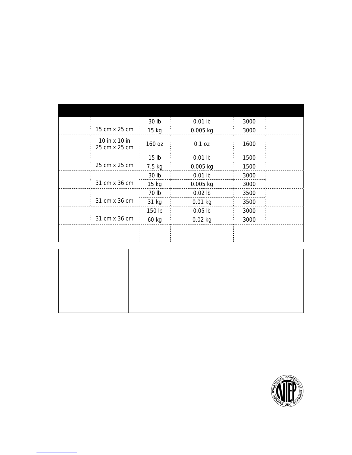
SPECIFICATIONS
Model Platform Size Capacity Increments Divisions Load Cell
APS10
APS160
APS15
APS30
APS70
APS150
APS250
Power Requirements: 100 to 240 VAC 50/60Hz 12 VDC 1A wall plug-in UL/CSA listed
Operating Environment: Temperature Range: 14º to 104º F (-10º to +40º C)
Display: Five digit, seven segment, 0.875 inch (22 mm) high LCD
6 in x 10 in
15 cm x 25 cm
10 in x 10 in
25 cm x 25 cm
10 in x 10 in
25 cm x 25 cm
12 in x 14 in
31 cm x 36 cm
12 in x 14 in
31 cm x 36 cm
12 in x 14 in
31 cm x 36 cm
18 in x 18 in
46 cm x 46 cm
30 lb 0.01 lb 3000
15 kg 0.005 kg 3000
160 oz 0.1 oz 1600 TSP-10kg
15 lb 0.01 lb 1500
7.5 kg 0.005 kg 1500
30 lb 0.01 lb 3000
15 kg 0.005 kg 3000
70 lb 0.02 lb 3500
31 kg 0.01 kg 3500
150 lb 0.05 lb 3000
60 kg 0.02 kg 3000
250 lb 0.1 lb 2500
125 kg 0.05 kg 2500
AC power adapter (Cardinal part number 6800-1045)
TSP-15kg
TSP-10kg
TSP-15kg
TSP-30kg
TSP-100kg
TSP-100kg
Interfaces: 2 RS-232 serial, 1 USB-B, 1 OPOS compatible serial, most POS
Options
Model APSWIFI – WiFi Model APSRD – Remote Display w/6ft. cable
Model APSBLU – Bluetooth Model BT1214 / BT1818 – Ball Top Transfer
Certifications
This equipment is certified to comply with the requirements for a Class III
device by the National Conference on Weights and Measurements (Certificate
Number: 14-057).
system protocols included (Cardinal Scale/SMA, Avery Berkel,
NCI/Worldship, Mettler PS, Mettler SICS)
8527-0544-2M Rev B APS Enterprise Scale 1
Page 6
INSTALLATION
Unpacking (APS10, APS160, APS15 and APS30)
Remove the scale from the shipping carton. Remove all packing material and then examine
the scale to make certain there is no shipping damage. Should damage be discovered contact
the shipping company as soon as possible. The packing material and shipping carton should
be retained for possible examination by the shipping company.
Determine where the scale is to be located. It should be a smooth surface capable of
supporting both the scale and any load to be placed on the scale. It should not be in direct
sunlight nor should it be subject to air flow from heating/cooling vents, fans or similar devices.
Plug-in the 12VDC adapter to use scale. Refer to Electrical Power section of this manual for
more instruction. The scale is now ready for use.
Unpacking and Setup (APS70 and APS150)
1. Remove the scale display, hardware pack, power supply, scale cover and scale base
assembly from the shipping carton. Remove all packing material and then examine the
scale to make certain there is no shipping damage. Should damage be discovered contact
the shipping company as soon as possible. The packing material and shipping carton
should be retained for possible examination by the shipping company.
2. Remove the four leveling feet from the hardware pack and install in each corner of the
bottom of the scale base. NOTE: Leveling feet must be in place to operate the scale.
3. To mount the display on the scale base, use the two included mounting screws in the
hardware pack. Insert the screws through the two holes in the scale display bracket and
attach the bracket to the scale base. Route the cable into the scale and plug into scale
display port (see interconnection section for port location and more information).
4. Determine where the scale is to be located. It should be a smooth surface capable of
supporting both the scale and any load to be placed on the scale. It should not be in direct
sunlight nor should it be subject to air flow from heating/cooling vents, fans or similar
devices.
5. Plug-in 12VDC adapter to use scale. Refer to Electrical Power section of this manual for
more instruction.
6. The scale is now ready for use.
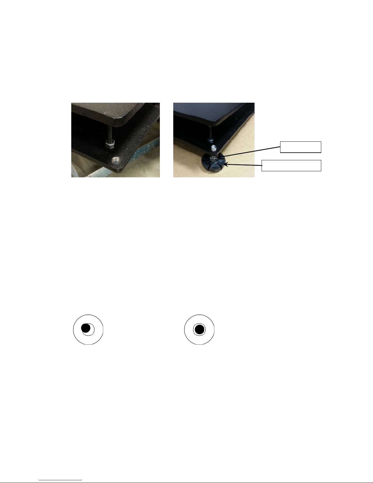
Level Adjustment
Place the scale in the chosen location and remove the stainless steel platform. The platform
can be removed by lifting upward on it removing it from the weighbridge. Locate the small
level indicator on the scale base to the right of the display and check to make certain that the
scale is level.
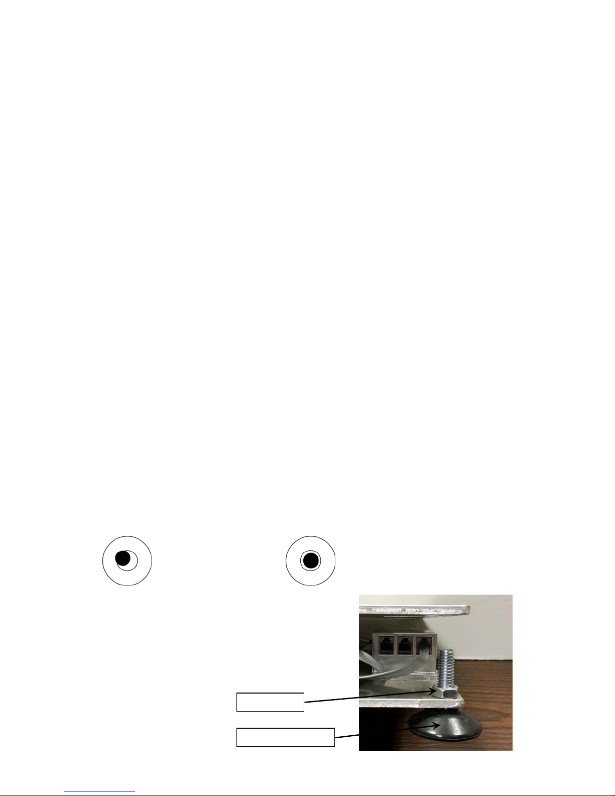
NOT LEVEL LEVEL
Bubble is not Bubble is
If the level indicator does not show a level indication, the
mounting feet should be adjusted to obtain a level
condition. To adjust a mounting foot, first loosen the lock
nut then turn the mounting foot in the required direction to
raise or lower that corner of the scale. Once a level
condition has been achieved, secure the mounting foot
settings by tightening each of the lock nuts. Replace the
platform on the weighbridge.
within circle within circle
LOCK NUT
MOUNTING FOOT
8527-0544-2M Rev B APS Enterprise Scale 2
Page 7
INSTALLATION, CONT.
Unpacking and Setup (APS250)
1. Remove the scale display, hardware pack, power supply, scale cover and scale base
assembly from the shipping carton. Remove all packing material and then examine the
scale to make certain there is no shipping damage. Should damage be discovered contact
the shipping company as soon as possible. The packing material and shipping carton
should be retained for possible examination by the shipping company.
2. Remove the four leveling feet from the hardware pack and install in each corner of the
bottom of the scale base. NOTE: Leveling feet must be in place to operate the scale.
LOCK NUT
MOUNTING FOOT
3. To mount the display on the scale base, use the two included mounting screws in the
hardware pack. Insert the screws through the two holes in the scale display bracket and
attach the bracket to the scale base. Route the cable into the scale and plug into scale
display port (see interconnection section for port location and more information).
4. Determine where the scale is to be located. It should be a smooth surface capable of
supporting both the scale and any load to be placed on the scale. It should not be in direct
sunlight nor should it be subject to air flow from heating/cooling vents, fans or similar
devices.
5. Plug-in 12VDC adapter to use scale. Refer to Electrical Power section of this manual for
more instruction.
6. The scale is now ready for use.
Level Adjustment
Place the scale in the chosen location and remove the stainless steel platform. The platform
can be removed by lifting upward on it removing it from the weighbridge. Locate the small
level indicator on the scale base to the right of the display and check to make certain that the
scale is level.
NOT LEVEL LEVEL
Bubble is not Bubble is
If the level indicator does not show a level indication, the mounting feet should be adjusted to
obtain a level condition. To adjust a mounting foot, first loosen the lock nut (located under the
scale base) and then turn the mounting foot in the required direction to raise or lower that
corner of the scale. Once a level condition has been achieved, secure the mounting foot
settings by tightening each of the lock nuts. Replace the platform on the weighbridge.
within circle within circle
8527-0544-2M Rev B APS Enterprise Scale 3
Page 8
INSTALLATION, CONT.
Electrical Power
The APS Enterprise scale has been designed to operate from a 100 to 240 VAC 50/60Hz 12
VDC 1A wall plug-in UL/CSA listed AC power adapter. Note that a special order is not
required for operation at 230 VAC.
On installations requiring 230 VAC power, it is the responsibility of the customer
to have a qualified electrician install the proper power adapter plug that conforms to
national electrical codes and local codes and ordinances.
Electrical Noise Interference
To prevent electrical noise interference, make certain all other wall outlets for use with air
conditioning and heating equipment, lighting or other equipment with heavily inductive loads,
such as welders, motors and solenoids are on circuits separate from the scale. Many of these
disturbances originate within the building itself and can seriously affect the operation of the
scale. These sources of disturbances must be identified and steps must be taken to prevent
possible adverse effects on the scale. Examples of available alternatives include isolation
transformers, power regulators, uninterruptible power supplies, or simple line filters.
Transient Suppression
The following recommendations will help to reduce transients:
Do not run signal cables from the scale along side or parallel to wiring carrying AC power.
If unavoidable, position the signal cables a minimum of 24" away from all AC wiring.
Always use arc suppressors across all AC power relay contacts (see recommendations at
http://www.paktron.com/pdf/Quencharch_QRL.pdf
).
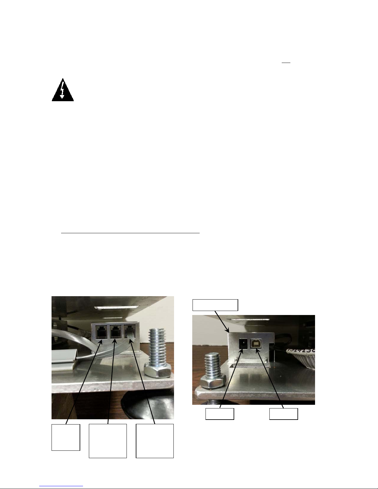
Interconnections
All input, output and power connections to the APS Enterprise scale are made internally to the
main board inside the scale. Connections for the scale display, remote display and OPOS
compatible serial device are made using RJ11 snap-in modular connectors. The USB port is a
device (or upstream) port using an industry standard “B” connector. The 12VDC 1A wall plugin UL/CSA listed AC power adapter is connected using a power jack.
POS
SERIAL
PORT 3
REMOTE
DISPLAY
SERIAL
PORT 2
8527-0544-2M Rev B APS Enterprise Scale 4
PCB COVER
12VDC USB
SCALE
DISPLAY
SERIAL
PORT 1
Page 9
INSTALLATION, CONT.
Data Cable Installation
SCALE DISPLAY/SERIAL PORT 1
Plug the RJ11 connector from the Scale Display cable into the scale base as marked.
REMOTE DISPLAY/SERIAL PORT 2
To use a remote display, plug the remote display RJ11 connector into the scale base where
marked.
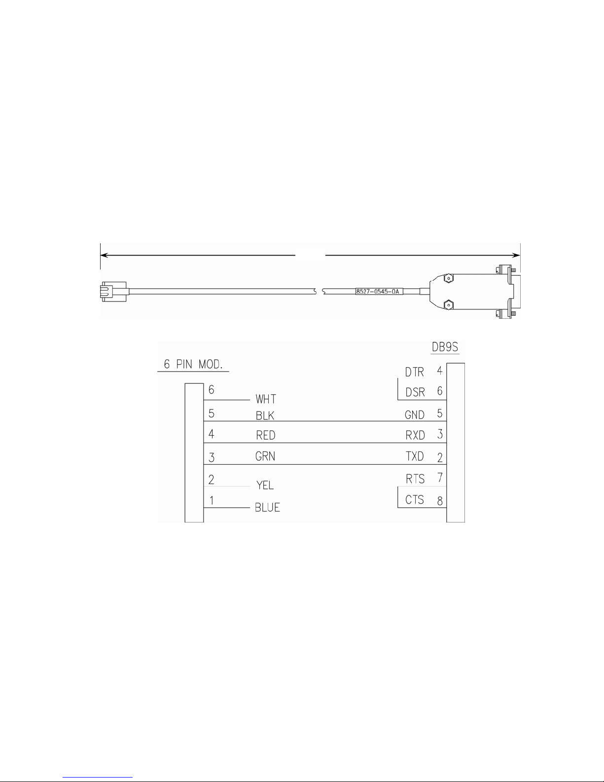
POS/SERIAL PORT 3
NOTE: The included serial data cable uses an RJ11 phone type connector (scale base) to
a DB9 connector (OPOS compatible serial device).
Plug the RJ11 connector of the included 4’ serial data cable into the scale base where marked
and then plug the other end into an available serial port on the POS device.
4 Feet
(4’ Included Serial Data Cable, 8527-0545-0A)
(Wiring Diagram, Serial Data Cable, 8527-0545-0A)
USB Cable Installation
USB
To use the USB interface, obtain a industry standard USB cable and plug it into the scale
base where marked and then plug the other end into a USB port on your computer.
Power Adapter
12VDC
To apply power to the scale using the supplied 12VDC 1A wall plug-in UL/CSA listed AC
power adapter, insert the plug from the power adapter cable into the power jack on the scale
base where marked (refer to previous page) and then plug the power adapter into a proper
electrical outlet. The scale is now ready for operation.
8527-0544-2M Rev B APS Enterprise Scale 5
Page 10

KEYPAD FUNCTIONS
DO NOT operate the keypad with pointed objects (pencils, pens, etc).
Damage to keypad resulting from this practice is NOT covered under warranty.
The keypad of the APS Enterprise Scale has two keys, ZERO (ON/OFF) and UNITS which
have the following functions:
This is the ZERO (ON/OFF) key. It serves several purposes. First, when the scale
is off, pressing it will turn the scale ON. If the scale is already on, pressing and
holding it for approximately 3 seconds will turn the scale OFF.
Pressing this key when the scale is on will zero the scale.
This is the UNITS key. This key is used to change the weighing units to the
alternate units of measurement. For example, with pounds displayed, pressing this
key will change the weighting units to kilograms.
ANNUNCIATORS
The annunciators are turned on to indicate that the display is in the mode corresponding to the
annunciator label or that the status indicated by the label is active.
OZ
This annunciator is turned on to indicate the weight displayed is in ounces.
lb
This annunciator is turned on to indicate that the displayed weight is in pounds.
kg
This annunciator is turned on to indicate the weight displayed is in kilograms.
(STABLE)
This annunciator is turned on when the weight display is stable. When off, it means that the
change in successive weight samples is greater than the motion limits selected during setup.
0 (ZERO)
The (0) annunciator is turned on to indicate that the weight is within +/- 1/4 division of the
center of zero.
8527-0544-2M Rev B APS Enterprise Scale 6
Page 11

SETUP AND CONFIGURATION
The keypad of the Enterprise has two keys, ZERO and UNITS which have the following
functionality when in setup mode:
ZERO – When a prompt is currently being shown (not the value of the prompt), pressing the
ZERO key will skip to the next prompt. If the value of a prompt is being shown,
pressing the ZERO key will toggle between the acceptable values for the current
prompt.
UNITS – When a prompt is currently being shown (not the value of the prompt), pressing the
UNITS key will display the value for that prompt. If the value of a prompt is being
shown, then pressing the UNITS key will save the current value and advance to
the next setup prompt.
To Enter Setup
1. Remove the Calibration Switch Access screw located
on the bottom of the scale.
2. With the scale ON, use a 1/8” or 3 mm Hex Key
Wrench or other small tool and press the Calibration
Switch.
3. The display will change to show type.
Type (Scale Type)
This will determine the capacity, interval, decimal, and converted units (if applicable).
Press the UNITS key to show current setting. If value displayed is acceptable, press the
UNITS key again to save it. Otherwise, press the ZERO key to step through selections for a
new value and then press the UNITS key to save it. The following types are selectable for
the Enterprise scale:
10
15
30
70
150
160
250
TEST
= APS10 30 lb x 0.01 lb (15 kg x 0.005 kg)
= APS15 15 lb x 0.01 lb (7.5 kg x 0.005 kg)
= APS30 30 lb x 0.01 lb (15 kg x 0.005 kg)
= APS70 70 lb x 0.02 lb (31 kg x 0.01 kg)
= APS150 150 lb x 0.05 lb (60 kg x 0.02 kg)
= APS160 160 oz x 0.1 oz
= APS250 250 lb x 0.1 lb (125 kg x 0.05 kg)
FACTORY TEST SETTINGS
UnS (Motion Range)
This is the motion range of the scale, or the number of divisions that the scale weight can
change without setting the motion indicator.
Press the UNITS key to show current setting. If value displayed is acceptable, press the
UNITS key again to save it. Otherwise, press the ZERO key to step through selections for
a new value and then press the UNITS key to save it.
Allowable values are 0 through 9.
Calibration Switch Access
8527-0544-2M Rev B APS Enterprise Scale 7
Page 12

SETUP AND CONFIGURATION, CONT.
FILtr (Adjustable Digital Filtering)
This is the adjustable digital weight filtering that is applied to the weight in order to help filter
out vibrations or other noise that might make the weight unstable.
Press the UNITS key to show current setting. If value displayed is acceptable, press the
UNITS key again to save it. Otherwise, press the ZERO key to step through selections for
a new value and then press the UNITS key to save it.
Allowable values are Off, 1, 2 or 3.
= No weight filtering
OFF
= Minimal weight filtering
1
= Moderate weight filtering
2
= Maximum weight filtering
3
CALIb (Calibration)
This is the calibration routine for the scale.
With display showing CALib, press the UNITS key. The display will change to show
current setting no. If scale has been previously calibrated and you wish to skip calibration
and proceed to PORT1, press the UNITS key again and internal calibration factor will be
retained.
To begin calibration, press the ZERO key to select yes and then press the UNITS key.
After pressing the UNITS key, the display will change to LOAd.
1. With “LOAd displayed, press the UNITS key. The display will change to show the
currently selected scale type’s capacity. NOTE: For convenience, you can press the
ZERO key and change this to half of capacity.
2. Once the test load weight is selected, placed the test load weight on the scale platform
and then press the UNITS key.
3. Starting at the right and proceeding left, a series of dashes will appear on the display
and then starting at the left and proceeding right disappear. Next, the display will
change to the UnLOd prompt.
4. Remove all weight from the scale platform and then press the UNITS key.
5. Starting at the right and proceeding left, a series of dashes will appear on the display
and then starting at the left and proceeding right disappear. Next, the display will
change to the PORT1 prompt. Calibration is complete. Proceed to PORT1.
8527-0544-2M Rev B APS Enterprise Scale 8
Page 13

SETUP AND CONFIGURATION, CONT.
PORt1 (RS-232 Serial Port 1)
This is the output format for the first serial port. It should default to “SnnA” in order to be
used with the Enterprise display.
The serial port parameters for this port are fixed at 9600 baud, 8 data bits, 1 stop bit and
No parity.
Press the UNITS key to show current setting. If value displayed is acceptable, press the
UNITS key again to save it. Otherwise, press the ZERO key to step through selections for
a new value and then press the UNITS key to save it.
Options for port output format are as follows:
SnnA
AUERY
nci
nntps
nntsi
PORt2 (RS-232 Serial Port 2)
This is the second serial port output format selection. It is identical to the PORT1,
including the serial port parameters for this port are fixed at 9600 baud, 8 data bits, 1 stop
bit and No parity.
Press the UNITS key to show current setting. If value displayed is acceptable, press the
UNITS key again to save it. Otherwise, press the ZERO key to step through selections for
a new value and then press the UNITS key to save it.
Cardinal/SMA, on-demand type output format
Avery output format
NCI output format
Mettler Toledo PS output format
Mettler Toledo SICS output format
Options for port2 output format are the same as PORT1.
PORt3 (POS Serial Port 3 – OPOS Compatible)
This is the third serial port output format selection. NOTE: The serial port parameters for
this port are fixed at 9600 baud, 7 data bits, 1 stop bit and Even parity. This is in order to
work with most POS systems that require NCI format. NOTE: The default format for this
port is NCI.
Press the UNITS key to show current setting. If value displayed is acceptable, press the
UNITS key again to save it. Otherwise, press the ZERO key to step through selections for
a new value and then press the UNITS key to save it.
Usb (USB Port)
The USB port output format selections are similar to the serial port settings. When
connected to a PC, this should appear as a virtual com port and can transmit weight using
any of the formats listed under PORt1.
Press the UNITS key to show current setting. If value displayed is acceptable, press the
UNITS key again to save it. Otherwise, press the ZERO key to step through selections for
a new value and then press the UNITS key to save it.
Options for USB output format are the same as PORT1.
8527-0544-2M Rev B APS Enterprise Scale 9
Page 14

SETUP AND CONFIGURATION, CONT.
HirES (High Resolution Weight Mode)
The High Resolution Weight Mode feature will display the weight at 10 times the standard
resolution. For example, an APS configured for 250 lb x 0.1 lb will display weight in high
resolution mode at 250 lb x 0.01 lb.
Press the UNITS key to show current setting. If value displayed is acceptable, press the
UNITS key again to save it. Otherwise, press the ZERO key to step through selections for
a new value and then press the UNITS key to save it.
Allowable values are YES or no.
YES = If High Resolution Weight
mode is
To exit the High Resolution Mode, press and hold the ZERO (ON/OFF) key to turn the
scale off and then press the ZERO (ON/OFF) to the scale back on
desired
NOTE: If YES is selected, the scale will exit Setup and Calibration, reset and
then display weight in the High Resolution Weight mode.
IMPORTANT! When the scale is in the High Resolution Weight mode, no Units
will be displayed and the scale is
no = High Resolution Weight mode is
not desired
not Legal For Trade.
ERROR AND STATUS DISPLAYS
Display Meaning
-Err-
----
Displayed when the ZERO key is pressed and the scale could not zero.
Displayed when scale weight exceeds scale capacity, or if there is an
analog high/low error.
8527-0544-2M Rev B APS Enterprise Scale 10
Page 15

REMOTE DISPLAY
The Remote Display can be mounted using three (3) methods.
The bracket can be attached to the wall using
the appropriate hardware for the type of wall
construction.
The remote display can be removed from the
bracket and mounted on the wall using the
included velcro
Using the remote display post, it can be
mounted to a table, bench or in a retail
environment, the checkstand.
®
strips.
8527-0544-2M Rev B APS Enterprise Scale 11
Page 16
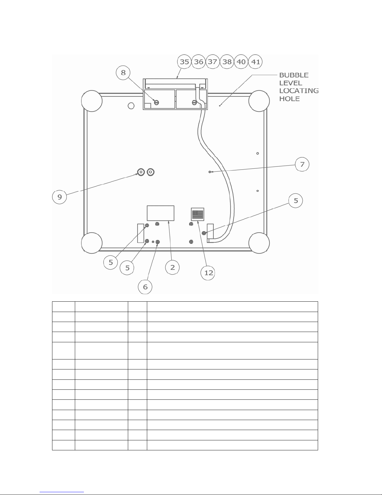
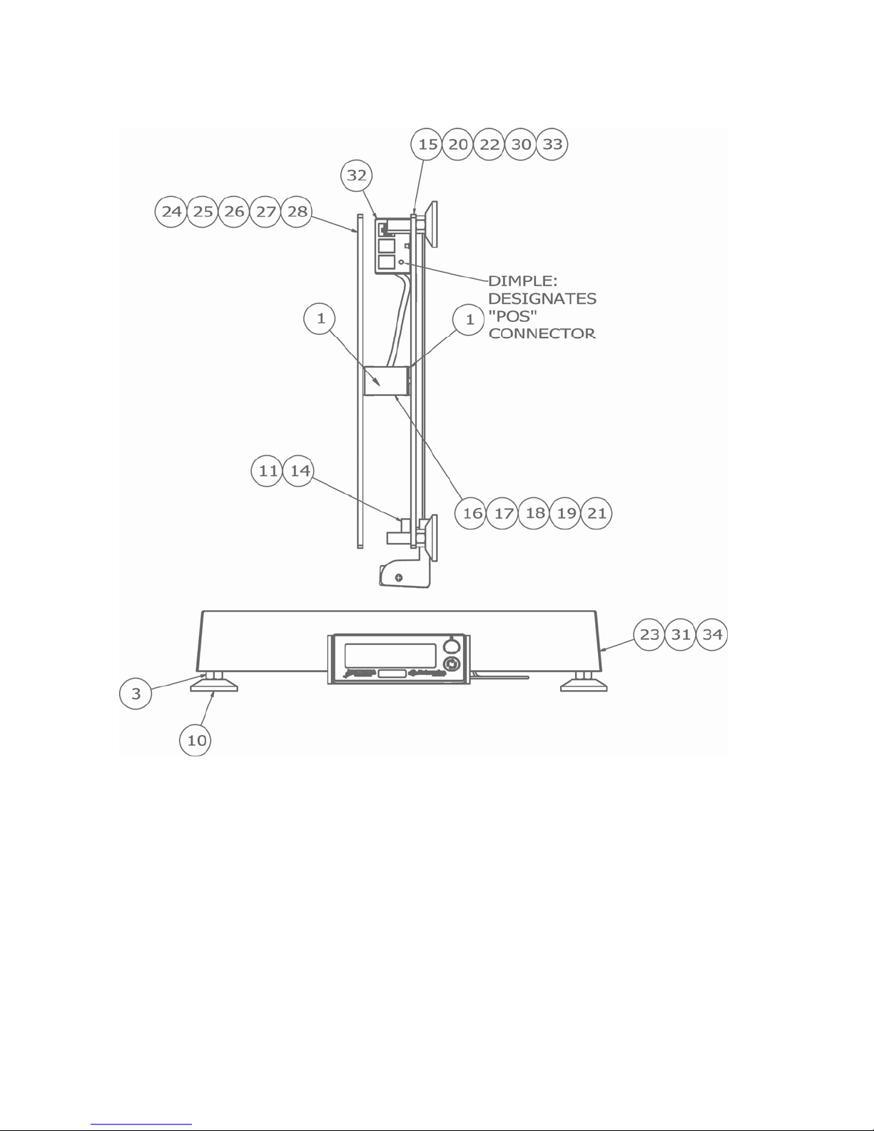
PARTS IDENTIFICATION
(APS10, APS160, APS15, APS30, APS70 and APS150)
ITEM PART NO. QTY DESCRIPTION
2 593GR986 1 SERIAL TAG ASSY
5 6021-0625 3 SCW FLAT-HEAD. MACHINE-SCW 06-32X.375
6 6021-0659 4 SCW FLAT-HEAD. MACHINE-SCW 06-32X1.00
7 6021-1069 2 SCW CUP-POINT. SET-SCREW.. 10-32X.25 NYLON
PATCH
8 6021-1108 2 SCW FILLISTER. MACHINE-SCW 10-32X.375
9 6021-1706 4 SCW FLAT-HEAD. CAP-SCREW.. .25-20X.625
12 6650-0087 1 LABEL, MADE IN USA (WITH FLAG) 1” X 1”
35 8527-D510-0A 1 DISPLAY SUB-ASSY, 10
36 8527-D510-1A 1 DISPLAY SUB-ASSY, 160
37 8527-D510-2A 1 DISPLAY SUB-ASSY, 15
38 8527-D510-3A 1 DISPLAY SUB-ASSY, 30
40 8527-D510-5A 1 DISPLAY SUB-ASSY, 70
41 8527-D510-6A 1 DISPLAY SUB-ASSY, 150
8527-0544-2M Rev B APS Enterprise Scale 12
Page 17

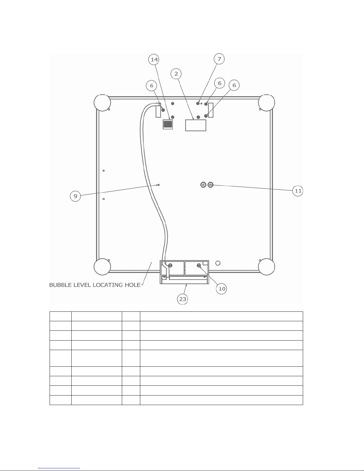
PARTS IDENTIFICATION, CONT.
(APS10, APS160, APS15, APS30, APS70 and APS150)
ITEM PART NO. QTY DESCRIPTION
1 1960-B465-08 2 SPACER FOR EB-XXX-XXXX
3 6013-0077 4 HEX NUT
10 6540-1165 4 LEVELLING FOOT, 1.63 BASE X 3/8”-16 X 1.3 STUD,
BLK PU
11 6560-1072 A/R ADHESIVE, LOCTITE 49
14 6690-0001 1 BULLSEYE BUBBLE LEVEL
15 8527-0519-08 1 BASE PLATE, 30
16 8527-0520-0A 1 CABLE ASSY, 10KG LC (APS15, APS160)
17 8527-0521-0A 1 CABLE ASSY, 15KG LC (APS10)
18 8527-0521-1A 1 CABLE ASSY, 15KG LC (APS30)
19 8527-0522-0A 1 CABLE ASSY, 30KG LC (APS70)
20 8527-0523-08 1 BASE PLATE, 150
21 8527-0524-0A 1 CABLE ASSY, 100KG LC (APS150)
22 8527-0527-08 1 BASE PLATE, 70
23 8527-0528-08 1 COVER, 12X14
24 8527-0529-08 TOP PLATE, 10
25 8527-0530-08 1 TOP PLATE, 160/15
26 8527-0531-08 1 TOP PLATE, 30
27 8527-0532-08 1 TOP PLATE, 70
28 8527-0533-08 1 TOP PLATE, 150
30 8527-C503-08 1 BASE PLATE, 10
31 8527-C504-08 1 COVER, 6X10
32 8527-C505-08 1 PCB COVER
33 8527-C513-08 1 BASE PLATE, 160/15
34 8527-C514-08 1 COVER, 10X10
A/R = AS REQUIRED
8527-0544-2M Rev B APS Enterprise Scale 13
Page 18
PARTS IDENTIFICATION, CONT.
(APS10, APS160, APS15, APS30, APS70 and APS150)
8527-0544-2M Rev B APS Enterprise Scale 14
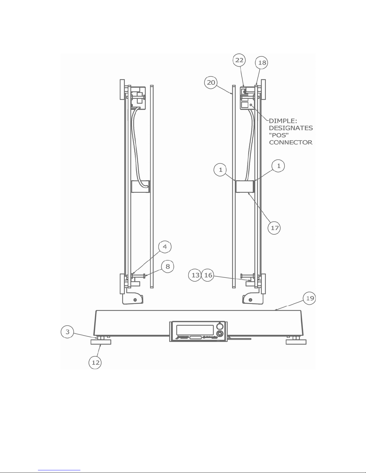
Page 19

PARTS IDENTIFICATION, CONT.
(APS10, APS160, APS15, APS30, APS70 and APS150)
ITEM PART NO. QTY DESCRIPTION
4 6021-0623 4 SCW PAN-HEAD.. MACHINE-SCW 06-32X.750
7 6021-1069 2 SCW CUP-POINT. SET-SCREW.. 10-32X.25 NYLON
PATCH
9 6021-1706 4 SCW FLAT-HEAD. CAP-SCREW.. .25-20X.625
13 6680-0004 4 WASHER LOCK INT TOOTH #6 TYPE A Z-PL
29 8527-C500-0A 1 ANALOG PCB
8527-0544-2M Rev B APS Enterprise Scale 15
Page 20
PARTS IDENTIFICATION, CONT.
(APS250)
ITEM PART NO. QTY DESCRIPTION
2 593GR986 1 SERIAL TAG ASSY
6 6021-0625 3 SCW FLAT-HEAD. MACHINE-SCW 06-32X.375
7 6021-0659 4 SCW FLAT-HEAD. MACHINE-SCW 06-32X1.00
9 6021-1069 1 SCW CUP-POINT. SET-SCREW.. 10-32X.25 NYLON
10 6021-1108 2 SCW FILLISTER. MACHINE-SCW 10-32X.375
11 6021-1706 4 SCW FLAT-HEAD. CAP-SCREW.. .25-20X.625
14 6650-0087 1 LABEL, MADE IN USA (WITH FLAG) 1” X 1”
23 8527-D510-7A 1 DISPLAY SUB-ASSY, 250
8527-0544-2M Rev B APS Enterprise Scale 16
PATCH
Page 21
PARTS IDENTIFICATION, CONT.
(APS250)
8527-0544-2M Rev B APS Enterprise Scale 17
Page 22

PARTS IDENTIFICATION, CONT.
(APS250)
ITEM PART NO. QTY DESCRIPTION
1 1960-B465-08 2 SPACER FOR EB-XXX-XXXX
3 6013-0077 4 HEX NUT
4 6013-0295 4 NUT #10-32 HEX Z/P
8 6021-0950 4 SCW HEX-HEAD.. MACHINE-SCW 10-32X1.50 Z/P
10 6021-1108 2 SCW FILLISTER. MACHINE-SCW 10-32X.375
12 6540-1123 4 LEVELLER SCREW, 3/8-16 X 1 1/4”, BLACK
13 6560-1072 A/R ADHESIVE, LOCTITE 49
16 6690-0001 1 BULLSEYE BUBBLE LEVEL
17 8527-0524-1A 1 CABLE ASSY, 100KG LC
18 8527-0525-08 1 BASE PLATE, 250
19 8527-0526-08 1 COVER, 18X18
20 8527-0534-08 1 TOP PLATE, 250
22 8527-C505-08 1 PCB COVER
A/R = AS REQUIRED
8527-0544-2M Rev B APS Enterprise Scale 18
Page 23
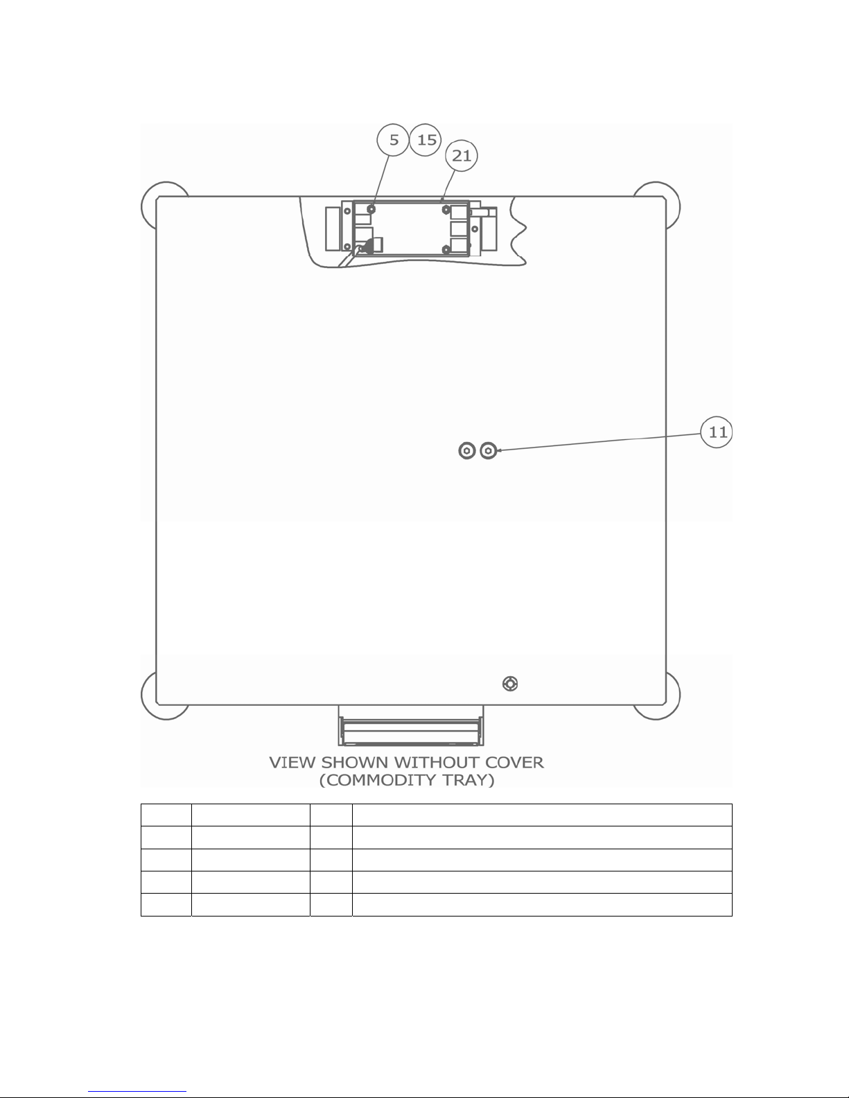
PARTS IDENTIFICATION, CONT.
(APS250)
ITEM PART NO. QTY DESCRIPTION
5 6013-0315 4 NUT #6-32 HEX SMALL PATTERN Z/P
11 6021-1706 4 SCW FLAT-HEAD. CAP-SCREW.. .25-20X.625
15 6680-0004 4 WASHER LOCK INT TOOTH #6 TYPE A Z-PL
21 8527-C500-0A 1 ANALOG PCB
8527-0544-2M Rev B APS Enterprise Scale 19
Page 24
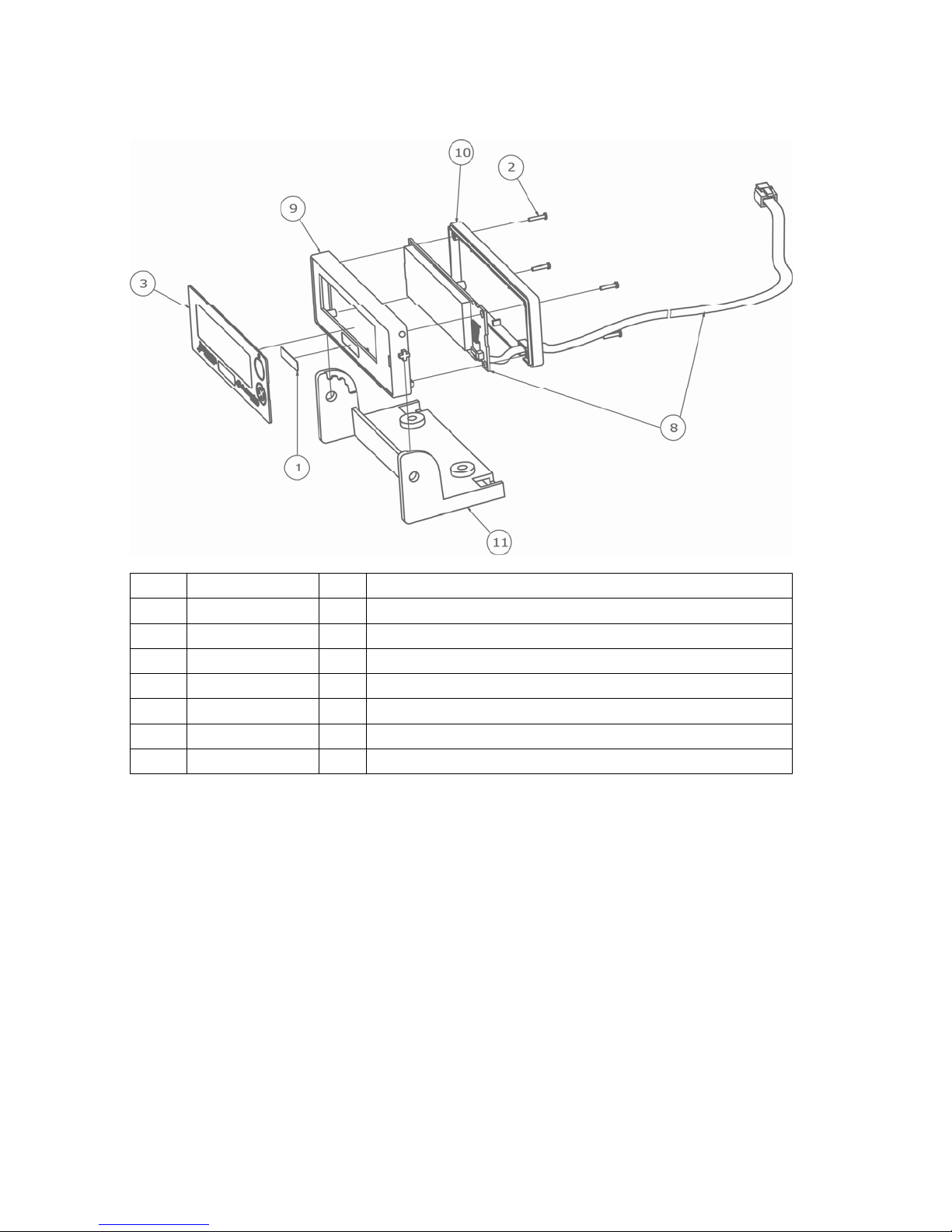
PARTS IDENTIFICATION, CONT.
(APSRD – APS REMOTE DISPLAY)
ITEM PART NO. QTY DESCRIPTION
1 5930-0146-08 1 CAPACITY LABEL
2 6021-2078 4 SCW PAN-HEAD PHILLIPS #1-32X3/8” THD FORM, SS
3 8527-0515-08 1 APS KEYPAD
8 8527-C502-4A 1 PCB ASSY APSRD DISPLAY
9 8527-D506-08 1 ENCLOSURE FRONT
10 8527-D507-08 1 ENCLOSURE BACK
11 8527-D508-08 1 ENCLOSURE MOUNT
8527-0544-2M Rev B APS Enterprise Scale 20
Page 25

8527-0544-2M Rev B APS Enterprise Scale 21
Page 26

8527-0544-2M Rev B APS Enterprise Scale 22
 Loading...