

Cardinal 6127 Series, 6337 Series, 6339 Series, 6129 Series Operating Instructions Manual

DIGITAL PHYSICIAN
(
Waist-High Scale
Model 6127 Series, 6129 Series
and
Eye-Level Scale
Models 6337 and 6339
Operating Instructions
8525-M310-O1 Rev C
10/12
Technical Support: Ph: 866-254-8261 x techsupport@cardet.com
CARDINAL SCALE MFG. CO.
PO BOX 151 x WEBB CITY, MO 64870
PH
417) 673-4631 x FAX(417) 673-5001
www.detectoscale.com
Printed in USA

DIGITAL PHYSICIAN WAIST-HIGH / EYE-LEVEL SCALE
Thank you for your purchase of our Detecto Digital Physician Waist-High or Detecto Digital
Physician Eye-Level scale. It has been manufactured with quality and reliability at our factory in
Webb City, MO USA. Your scale has been tested before leaving our factory to insure accuracy
and dependability for years to come.
This manual will guide you through assembly, installation, and operation of your scale. Please
read it thoroughly before attempting to use your scale and keep it handy for future reference.
FCC COMPLIANCE STATEMENT
WARNING! This equipment generates uses and can radiate radio frequency and if not installed
and used in accordance with the instruction manual, may cause interference to radio
communications. It has been tested and found to comply with the limits for a Class A computing
device pursuant to Subpart J of Part 15 of FCC rules, which are designed to provide reasonable
protection against such interference when operated in a commercial environment. Operation of
this equipment in a residential area may cause interference in which case the user will be
responsible to take whatever measures necessary to correct the interference.
You may find the booklet "How to Identify and Resolve Radio TV Interference Problems"
prepared by the Federal Communications Commission helpful. It is available from the U.S.
Government Printing Office, Washington, D.C. 20402. Stock No. 001-000-00315-4.
All rights reserved. Reproduction or use, without expressed written permission, of editorial or pictorial content, in any
manner, is prohibited. No patent liability is assumed with respect to the use of the information contained herein. While
every precaution has been taken in the preparation of this manual, the Seller assumes no responsibility for errors or
omissions. Neither is any liability assumed for damages resulting from use of the information contained herein. All
instructions and diagrams have been checked for accuracy and ease of application; however, success and safety in
working with tools depend to a great extent upon the individual accuracy, skill and caution. For this reason the Seller is
not able to guarantee the result of any procedure contained herein. Nor can they assume responsibility for any
damage to property or injury to persons occasioned from the procedures. Persons engaging the procedures do so
entirely at their own risk.
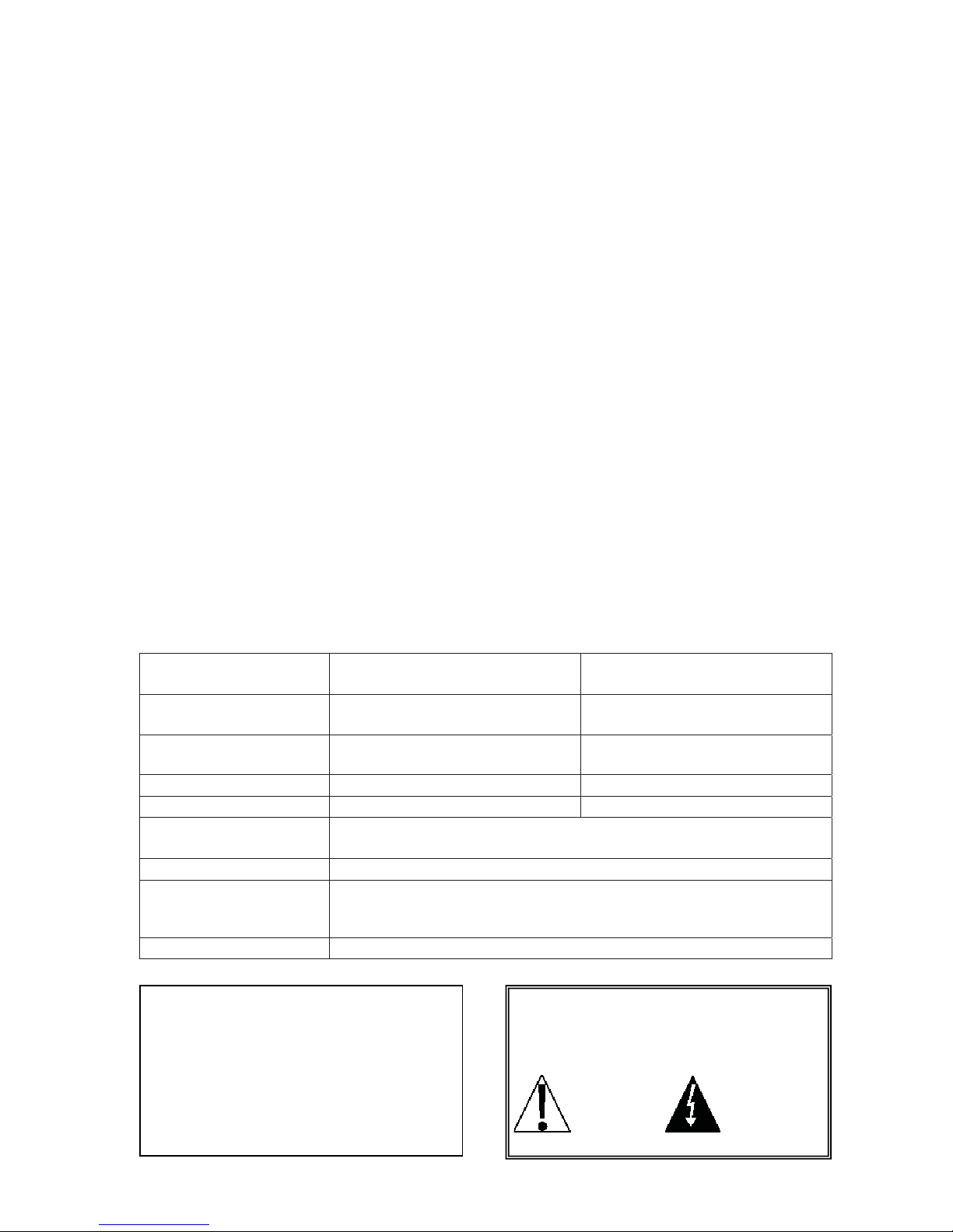
Waist-High Eye-Level
Capacity …...…..…...…… 550 lb x .2 lb
(250 kg x .1 kg), selectable
Platform Size ......…...….. 10 5/8” x 14 1/2”
(270 mm x 368 mm)
Dimensions ..................... 10 7/8” W x 20 7/8” D x 37 7/8” H
(276 mm x 530 mm x 962 mm)
550 lb x .2 lb
(250 kg x .1 kg), selectable
10 5/8” x 14 1/2”
(270 mm x 368 mm)
10 7/8” W x 20 7/8” D x 57 1/2” H
(276 mm x 530 mm x 1461 mm)
Shipping Weight ……...… 34 lb (15.4 kg) 36 lb (16.3 kg)
Scale Height ..…….…..... 37 1/2 ” (953 mm) 57 1/8” (1451 mm)
Height Rod Measures ..... 6129, 6129KG, 6339 - 30” to 78” (76 cm to 200 cm) x inch/cm
6129KGM - 30” to 78” (76 cm to 200 cm) by 1/4”/1mm
Display ….……………….. Six digit, Seven segment, 0.7 inch (17.8 mm) high LCD
Power ....……………….... 6 “AA” size Alkaline, Ni-Cad or NiMH batteries (not included) OR an
optional 100 to 240 VAC 50/60Hz 12 VDC 1A wall plug-in UL/CSA
listed AC power adapter (Cardinal part number 6800-1045).
Keyboard .…………......... Membrane type with 5 keys and 4 directional arrows
Serial Number_______________________
Date of Purchase ____________________
Before using this instrument, read this
PRECAUTIONS
manual and pay special attention to all
Purchased Form_____________________
"WARNING" symbols:
___________________________________
___________________________________
RETAIN THIS INFORMATION FOR FUTURE USE
8525-M310-O1 Rev C x 612X Series and 633X Series
IMPORTANT ELECTRICAL
WARNING
1

UNPACKING INSTRUCTIONS
x Remove scale from carton by lifting up with equal force from column and platform base.
x Check for any damage incurred in shipping. If scale has been damaged, place a claim with the
carrier. Use the original carton and shipping material to return the scale.
x Remove all plastic wrapping, foam fillers and cardboard material from the scale.
x Remove and unpack the power supply and cord, if the scale was ordered with this option.
x Carton contents:
1) Column
2) Indicator
3) Platform base
4) Screws and lock washers
5) Height measuring rod - optional
NOTE! If column bracket is bent,
straighten before assembling.
ASSEMBLY INSTRUCTIONS
Refer to Figures No. 1, 2, 3, and 4, then follow the instructions for scale assembly.
1. Carefully remove load cell and draft rod assembly from column.
IMPORTANT! Handle load cell assembly with care! Do not drop, bend or twist.
2. Slip column over column bracket on platform base. Screw column to column brackets (two
1/4 truss head screws in front of column and four in the back). See Figure No. 1.
3. Referring to Figure No. 2, remove both #10-32 Truss Head Screws and lock washers
securing the indicator bracket to the column.
4. Lower load cell and draft rod assembly into column. Draft Rod must pass through opening in
column bracket. Referring to Figure No 1, make sure open end of lower draft rod hook is
facing forward toward platform.
5. Next, referring to Figure No. 3, fasten top hook bolt of load cell assembly (C) to column.
Make sure the load cell assembly does not touch the sides of column.
6. Slide grommet away from load cell assembly and slide into slot on column. NOTE! The slot
should be on back (wide side) of column.
7. Pull excess load cell cable in column leaving enough slack in cable so as not to have any
side pull on load cell.
8. Place digital indicator bracket on column and attach with 2 (#10-32) truss head screws and
lock washers removed in step 3. See Figure No. 2.
9. Using a desk or table, lay down scale with column horizontal to floor. Raise draft rod
keeping out of lever's way. Push lever. When lever is in position, hook draft rod around
pivot. See Figure No. 4.
10. Attach indicator to indicator bracket on column, then connect load cell cable to back of
indicator. Refer to the 750 Weight Indicator Owner’s Manual (8555-M483-O1) for additional
information.
11. Scale is now ready for operation.
2
8525-M310-O1 Rev C x 612X Series and 633X Series

ASSEMBLY INSTRUCTIONS, CONT.
Grommet
Load
Cell
Cable
Figure No. 1
Figure No. 3
Column
C
Draft
Rod
Opening
#10-32 Truss
Head Screw
Column
Bracket
Raise
Draft
Rod
Push
Lever
Figure No. 4
Indicator
Bracket
Lock
Washer
Figure No. 2
8525-M310-O1 Rev C x3 612X Series and 633X Series
 Loading...