

Page 1

(
210
WEIGHT INDICATOR
Installation and Technical Manual
8200-M585-O1 Rev D
11/14
www.cardinalscale.com
Technical Support: Ph: 866-254-8261 techsupport@cardet.com
8200-M585-O1 Rev D 210 Installation & Technical 1
PO BOX 151
417) 673-4631 FAX (417) 673-5001
PH
WEBB CITY, MO 64870
Printed in USA
Page 2

8200-M585-O1 Rev D 210 Installation & Technical 2
Page 3
INTRODUCTION
Thank you for selecting and purchasing the Cardinal Model 210 Weight Indicator. The Model
210 was built with quality and reliability at our factory in Webb City, Missouri and incorporates
the latest in digital technology and innovative features for the weighing industry. Configuration
and upgrades can easily be performed in the field, while still maintaining the rigid control the
most demanding installations require. This flexibility insures the Model 210 will be able to
meet your weight indicating needs for years to come.
The purpose of this manual is to provide you with a guide through installation, setup and
operation of your new Model 210 Weight Indicator. Please read it thoroughly before
attempting to install your weight indicator and keep it handy for future reference.
COPYRIGHT
All rights reserved. Reproduction or use, without expressed written permission, of editorial or
pictorial content, in any manner, is prohibited. No patent liability is assumed with respect to
the use of the information contained herein.
DISCLAIMER
While every precaution has been taken in the preparation of this manual, the Seller assumes
no responsibility for errors or omissions. Neither is any liability assumed for damages resulting
from use of the information contained herein. All instructions and diagrams have been
checked for accuracy and ease of application; however, success and safety in working with
tools depend to a great extent upon the individual accuracy, skill and caution. For this reason
the Seller is not able to guarantee the result of any procedure contained herein. Nor can they
assume responsibility for any damage to property or injury to persons occasioned from the
procedures. Persons engaging the procedures do so entirely at their own risk.
SERIAL NUMBER _____________________
DATE OF PURCHASE _________________
PURCHASED FROM __________________
____________________________________
____________________________________
RETAIN THIS INFORMATION FOR FUTURE US E
PRECAUTIONS
Before using this indicator, read this manual and pay special attention to all
"NOTIFICATION" symbols:
IMPORTANT
ELECTRICAL
WARNING
STATIC
SENSITVE
8200-M585-O1 Rev D 210 Installation & Technical I
Page 4
FCC COMPLIANCE STATEMENT
This equipment generates uses and can radiate radio frequency and if not installed and used
in accordance with the instruction manual, may cause interference to radio communications. It
has been tested and found to comply with the limits for a Class A computing device pursuant
to Subpart J of Part 15 of FCC rules, which are designed to provide reasonable protection
against such interference when operated in a commercial environment. Operation of this
equipment in a residential area may cause interference in which case the user will be
responsible to take whatever measures necessary to correct the interference.
You may find the booklet “How to Identify and Resolve Radio TV Interference Problems”
prepared by the Federal Communications Commission helpful. It is available from the U.S.
Government Printing Office, Washington, D.C. 20402. The stock number is 001-000-00315-4.
PROPER DISPOSAL
When this device reaches the end of its useful life, it must be properly disposed of. It must not
be disposed of as unsorted municipal waste. Within the European Union, this device should
be returned to the distributor from where it was purchased for proper disposal. This is in
accordance with EU Directive 2002/96/EC. Within North America, the device should be
disposed of in accordance with the local laws regarding the disposal of waste electrical and
electronic equipment.
It is everyone’s responsibility to help maintain the environment and to reduce
the effects of hazardous substances contained in electrical and electronic
equipment on human health. Please do your part by making certain that this
device is properly disposed of. The symbol shown to the right indicates that
this device must not be disposed of in unsorted municipal waste programs.
CAUTION
CAUTION: RISK OF EXPLOSION IF BATTERY IS REPLACED BY AN
INCORRECT TYPE. DISPOSE OF USED BATTERIES ACCORDING TO THE
INSTRUCTIONS.
ATTENTION: RISQUE D'EXPLOSION SI LA BATTERIES EST REMPLACE'E PAR
UN TYPE INCORRECT. REJETEZ LES BATTERIES UTILISE'ES SELON LES
INSTRUCTIONS.
8200-M585-O1 Rev D 210 Installation & Technical II
Page 5

TABLE OF CONTENTS
SPECIFICATIONS - - - - - - - - - - - - - - - - - - - - - - - - - - - - - - - - - - - - - - - - - - - - - - - - Page 1
Standard Features - - - - - - - - - - - - - - - - - - - - - - - - - - - - - - - - - - - - - - - - - - - - - - Page 2
Optional Features - - - - - - - - - - - - - - - - - - - - - - - - - - - - - - - - - - - - - - - - - - - - - - Page 2
PRECAUTIONS - - - - - - - - - - - - - - - - - - - - - - - - - - - - - - - - - - - - - - - - - - - - - - - - - Page 3
SITE PREPARATION REQUIREMENTS - - - - - - - - - - - - - - - - - - - - - - - - - - - - - - - - Page 5
INSTALLATION - - - - - - - - - - - - - - - - - - - - - - - - - - - - - - - - - - - - - - - - - - - - - - - - - - Page 7
Mounting - - - - - - - - - - - - - - - - - - - - - - - - - - - - - - - - - - - - - - - - - - - - - - - - - - - - - Page 7
Load Cell Cable Connection for RFI Suppression - - - - - - - - - - - - - - - - - - - - - - - - Page 8
Load Cell Cable Connection (Standard Gland Connector) - - - - - - - - - - - - - - - - - - Page 9
Load Cell Connections With Over 30 Feet Of Cable - - - - - - - - - - - - - - - - - - - - - - Page 9
Serial I/O Cable Installation - - - - - - - - - - - - - - - - - - - - - - - - - - - - - - - - - - - - - - - - Page 10
USB Interface and USB Cable Installation - - - - - - - - - - - - - - - - - - - - - - - - - - - - - Page 12
Main PC Board I/O Functions Table - - - - - - - - - - - - - - - - - - - - - - - - - - - - - - - - - - Page 13
RB4/RB8 Relay Box Cable Wire Number To Relay Number Table - - - - - - - - - - - - Page 13
Optically Isolated Remote Inputs - - - - - - - - - - - - - - - - - - - - - - - - - - - - - - - - - - - - Page 14
AC Input Relay Board(s) - - - - - - - - - - - - - - - - - - - - - - - - - - - - - - - - - - - - - - - - - Page 14
PWC/Checkweigher Logic Level Output - - - - - - - - - - - - - - - - - - - - - - - - - - - - - - Page 16
AC Output Relay Board(s) - - - - - - - - - - - - - - - - - - - - - - - - - - - - - - - - - - - - - - - - Page 17
RB4C Relay J-Box - - - - - - - - - - - - - - - - - - - - - - - - - - - - - - - - - - - - - - - - - - - - - - Page 18
Main PCB (Figure No. 15) - - - - - - - - - - - - - - - - - - - - - - - - - - - - - - - - - - - - - - - - - Page 19
Main PCB Jumpers - - - - - - - - - - - - - - - - - - - - - - - - - - - - - - - - - - - - - - - - - - - - - Page 20
Re-Installing The Rear Panel - - - - - - - - - - - - - - - - - - - - - - - - - - - - - - - - - - - - - - Page 20
KEYPAD FUNCTIONS - - - - - - - - - - - - - - - - - - - - - - - - - - - - - - - - - - - - - - - - - - - - - Page 21
ANNUNCIATORS - - - - - - - - - - - - - - - - - - - - - - - - - - - - - - - - - - - - - - - - - - - - - - - - Page 29
SETUP AND CALIBRATION - - - - - - - - - - - - - - - - - - - - - - - - - - - - - - - - - - - - - - - - - Page 31
Setup - - - - - - - - - - - - - - - - - - - - - - - - - - - - - - - - - - - - - - - - - - - - - - - - - - - - - - - Page 32
Analog to Digital Filtering - - - - - - - - - - - - - - - - - - - - - - - - - - - - - - - - - - - - - - - - - Page 37
Calibration - - - - - - - - - - - - - - - - - - - - - - - - - - - - - - - - - - - - - - - - - - - - - - - - - - - - Page 41
Setup Guardian Scale - - - - - - - - - - - - - - - - - - - - - - - - - - - - - - - - - - - - - - - - - - - Page 45
Mode of Operation - - - - - - - - - - - - - - - - - - - - - - - - - - - - - - - - - - - - - - - - - - - - - - Page 45
0 = Normal Scale - - - - - - - - - - - - - - - - - - - - - - - - - - - - - - - - - - - - - - - - - - - - - Page 45
1 = ID Storage - - - - - - - - - - - - - - - - - - - - - - - - - - - - - - - - - - - - - - - - - - - - - - - Page 46
2 = Digital Fill Control - - - - - - - - - - - - - - - - - - - - - - - - - - - - - - - - - - - - - - - - - - Page 46
3 = Preset Weight Comparator - - - - - - - - - - - - - - - - - - - - - - - - - - - - - - - - - - - Page 48
4 = Checkweigher - - - - - - - - - - - - - - - - - - - - - - - - - - - - - - - - - - - - - - - - - - - - Page 49
5 = Axle Weigher - - - - - - - - - - - - - - - - - - - - - - - - - - - - - - - - - - - - - - - - - - - - - Page 50
6 = Livestock Weigher - - - - - - - - - - - - - - - - - - - - - - - - - - - - - - - - - - - - - - - - - Page 52
Serial Input/Output - - - - - - - - - - - - - - - - - - - - - - - - - - - - - - - - - - - - - - - - - - - - - - Page 53
Print Tab Settings - - - - - - - - - - - - - - - - - - - - - - - - - - - - - - - - - - - - - - - - - - - - - - Page 63
Fine Span Adjustment - - - - - - - - - - - - - - - - - - - - - - - - - - - - - - - - - - - - - - - - - - - Page 65
Display High Resolution Weight- - - - - - - - - - - - - - - - - - - - - - - - - - - - - - - - - - - - - Page 65
Key Lock Out Function - - - - - - - - - - - - - - - - - - - - - - - - - - - - - - - - - - - - - - - - - - - Page 65
Option Card Configuration - - - - - - - - - - - - - - - - - - - - - - - - - - - - - - - - - - - - - - - - Page 65
SETUP REVIEW - - - - - - - - - - - - - - - - - - - - - - - - - - - - - - - - - - - - - - - - - - - - - - - - - Page 67
CALIBRATION "C" NUMBERS - - - - - - - - - - - - - - - - - - - - - - - - - - - - - - - - - - - - - - - Page 69
8200-M585-O1 Rev D 210 Installation & Technical III
Page 6

TABLE OF CONTENTS,CONT.
ACCUMULATORS - - - - - - - - - - - - - - - - - - - - - - - - - - - - - - - - - - - - - - - - - - - - - - - - Page 71
TROUBLESHOOTING - - - - - - - - - - - - - - - - - - - - - - - - - - - - - - - - - - - - - - - - - - - - -
Error Codes - - - - - - - - - - - - - - - - - - - - - - - - - - - - - - - - - - - - - - - - - - - - - - - - - - Before You Call Service - - - - - - - - - - - - - - - - - - - - - - - - - - - - - - - - - - - - - - - - - - Page 76
Diagnostic Test Mode - - - - - - - - - - - - - - - - - - - - - - - - - - - - - - - - - - - - - - - - - - - CALIBRATION SEAL INSTALLATION - - - - - - - - - - - - - - - - - - - - - - - - - - - - - - - - - - Page 78
ID STORAGE OPERATION - - - - - - - - - - - - - - - - - - - - - - - - - - - - - - - - - - - - - - - - - Page 79
DIGITAL FILL CONTROL MODE OPERATION - - - - - - - - - - - - - - - - - - - - - - - - - - - Page 87
DIGITAL FILL CONTROL ID STORAGE - - - - - - - - - - - - - - - - - - - - - - - - - - - - - - - - Page 95
AXLE WEIGHER OPERATION MODE - - - - - - - - - - - - - - - - - - - - - - - - - - - - - - - - - Page 99
LIVESTOCK WEIGHER MODE OPERATION - - - - - - - - - - - - - - - - - - - - - - - - - - - - Page 103
MODEL 210DC - - - - - - - - - - - - - - - - - - - - - - - - - - - - - - - - - - - - - - - - - - - - - - - - - - Page 105
LOCAL/REMOTE SETUP - - - - - - - - - - - - - - - - - - - - - - - - - - - - - - - - - - - - - - - - - - - Page 106
PART IDENTIFICATION - - - - - - - - - - - - - - - - - - - - - - - - - - - - - - - - - - - - - - - - - - - Page 108
Page 73
Page 73
Page 77
8200-M585-O1 Rev D 210 Installation & Technical IV
Page 7

SPECIFICATIONS
Power Requirements: 100 to 240 VAC (50/60 Hz) at 0.4A Max.
Enclosure Type: Stainless Steel wall or desk-mount
Enclosure Size:
Weight: 8.2 lb (3.7 kg)
Operating Environment:
Display:
Transducer Excitation: 9.4 VDC
Signal Input Range: 1.0 mV min. to 40 mV max. (with dead load boost)
Number of Load Cells: 8 each, 350-ohm load cells
Load Cell Cable Length:
Division Value:
Sensitivity:
NON-COMMERCIAL
NTEP
CANADA
OIML
Scale Divisions:
NON-COMMERCIAL
NTEP
CANADA
OIML
Internal Resolution: 1 part in 16,777,216
Tare Capacity: Scale Capacity
Sample Rate: 1 to 100 samples per second, selectable
Auto Zero Range: 0.5 or 1 through 9 divisions
Weighing Units:
Keypad: Color coded Membrane type, 22 keys
Standard I/O:
9 3/16" W x 7 1/2" H x 3 1/8" D
(233 mm W x 191 mm H x 79 mm D)
Compensated Temperature Range: 14º to 104º F (-10º to +40º C)
Operated Temperature Range: -10º to 122º F (-23º to +50º C)
Humidity: 0 to 90% non-condensing
Six digit, seven segment, 0.6" (15 mm) high LED
1,500 feet maximum (requires the use of sense lines). Consult
factory for other requirements
30 feet maximum without sense lines
Commercial: 1, 2, or 5 x 10, 1, 0.1, 0.01, 0.001
Non-commercial: 1 to 99 x 10, 1, 0.1, 0.01, 0.001.
0.15 uV/e
0.3uV/e (Class III/IIIL)
0.3uV/e (Class III/IIIHD)
0.5 uV/e (Class III)
100 to 240,000
500 to 10,000 (Class III/IIIL)
500 to 10,000 (Class III/IIIHD)
500 to 10,000 (Class III)
Tons, Pounds, Pounds-Ounces, Ounces, Metric Tons, Kilograms,
and Grams
4 ea Serial I/O Ports configured as:
4 ea bi-directional RS-232 ports
1 ea 20mA output-only ports (uses one of the four RS-232 ports)
1 ea bi-directional 20mA port (uses one of the four RS-232 ports)
1 ea USB port (uses one of the four RS-232 ports)
8 ea Remote Isolated Inputs
8 ea Remote Isolated Outputs
8200-M585-O1 Rev D 210 Installation & Technical 1
Page 8

Standard Features:
• Push button tare function
• Gross, tare, net conversion
• Selectable key lockout
• Hi-Resolution mode
• StableSENSE
® 1
adjustable digital filtering
• Gross and Net accumulators
• Four serial ports
• Eight (8) remote input lines for Zero, Tare, Gross, Units, Start, Stop and Print
(1000 feet maximum)
• Programmable print format using Visual Print or nControl (2 Visual Tickets available)
• SMA level 2 compliant serial communications
(For more information see http://www.scalemanufacturers.org)
• Field re-programmable via PC interconnection
• Test feature (performs display and internal tests)
• Auto Shutoff and Sleep modes
• Alphanumeric keypad
• Keypad tare function
• Count feature with accumulator
• Time and Date with selectable 12 or 24 hour operation
• Checkweigher
• Eight (8) Preset Weight Comparators
• Axle Weigher (CWL-40) Operation Mode
• Animal Weigher
• ID Storage
• 2-Speed Fill Control
• USB Interface
Optional Features:
Analog Output*, Allen-Bradley Interface*, 10/100 mbps Ethernet Adapter*, Additional Serial
Port*, USB-A Option Card*, Checkweigher Light Bar*, Internal Relay Box*, External Relay
Box*, Special Filtering, and Column Mounting
*This feature requires additional hardware and includes additional documentation.
1
StableSENSE® is a digital filter utilizing proprietary software algorithms to remove or greatly
reduce changes in the weight display resulting from movement on the scale platform.
StableSENSE
the animal’s movement on the scale or it can be used with vehicle scales to lessen the
effects of wind and vehicle vibration. Any application affected by vibration or movement on
the scale platform can benefit using StableSENSE
®
can be used with livestock and single animal scales to lessen the effects of
®
.
8200-M585-O1 Rev D 210 Installation & Technical 2
Page 9
Static Electricity
CAUTION! This device contains static sensitive circuit cards and components.
Improper handling of these devices or printed circuit cards can result in damage to or
destruction of the component or card. Such actual and/or consequential damage IS
NOT covered under warranty and is the responsibility of the device owner. Electronic
components must be handled only by qualified electronic technicians who follow the
guidelines listed below.
WARNING! ALWAYS use a properly grounded wrist strap when handling, removing
or installing electronic circuit cards or components. Make certain that the wrist strap
ground lead is securely attached to an adequate ground. If you are uncertain of the
quality of the ground, you should consult a licensed electrician.
ALWAYS handle printed circuit card assemblies by the outermost edges. NEVER
touch the components, component leads or connectors. ALWAYS observe warning
labels on static protective bags and packaging and never
component from the packaging until ready for use. ALWAYS store and transport
electronic printed circuit cards and components in anti-static protective bags or
packaging.
PRECAUTIONS
remove the card or
8200-M585-O1 Rev D 210 Installation & Technical 3
Page 10

8200-M585-O1 Rev D 210 Installation & Technical 4
Page 11
SITE PREPARATION REQUIREMENTS
The Cardinal 210 indicator is a precision weight-measuring instrument. As with any precision
instrument, they require an acceptable environment to operate at peak performance and
reliability. This section is provided to assist you in obtaining such an environment.
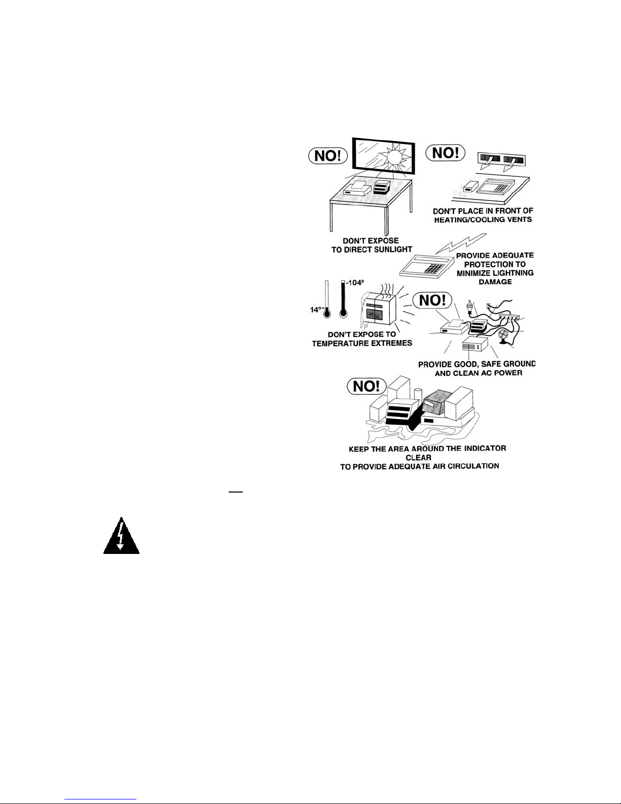
Environmental
The Model 210 indicator meet or exceeds
all certification requirements within a
temperature range of 14 to 104 °F (-10 to
+40 °C).
In order to keep cooling requirements to a
minimum, the indicator should be placed
out of direct sunlight and to provide
adequate air circulation, keep the area
around the indicator clear.
Make certain the indicator is not directly in
front of a heating or cooling vent. Such a
location will subject the indicator to
sudden temperature changes, which may
result in unstable weight readings.
Insure that the indicator has good, clean
AC power and is properly grounded.
In areas subject to lightning strikes,
additional protection to minimize lightning
damage, such as surge suppressors,
should be installed.
Electrical Power
The 210 indicator has been designed to
operate from 100 to 240 VAC at 50/60 Hz.
Note that a special order is not
for operation at 230/240 VAC.
WARNING! To avoid electrical hazard and possible damage to the indicator,
DO NOT, under any circumstance, cut, remove, alter, or in any way bypass the
power cord grounding prong.
The socket-outlet supplying power to the indicator should be on a separate circuit from the
distribution panel and dedicated to the exclusive use of the indicator.
required
The socket-outlet shall be installed near the equipment and shall be easily accessible.
Note that the power cord on the 210 serves as the power disconnect.
The wiring should conform to national and local electrical codes and ordinances and should
be approved by the local inspector to assure compliance.
For outdoor operations, the socket-outlet must provide GFCI (ground fault circuit
interrupter) protection.
On installations requiring 230/240 VAC power, it is the responsibility of the customer to
have a qualified electrician install the proper power cord plug that conforms to national
electrical codes and local codes and ordinances.
8200-M585-O1 Rev D 210 Installation & Technical 5
Page 12

SITE PREPARATION REQUIREMENTS, CONT.
Electrical Noise Interference
To prevent electrical noise interference, make certain all other wall outlets for use with air
conditioning and heating equipment, lighting or other equipment with heavily inductive loads,
such as welders, motors and solenoids are on circuits separate from the indicator. Many of
these disturbances originate within the building itself and can seriously affect the operation of
the indicator. These sources of disturbances must be identified and steps must be taken to
prevent possible adverse effects on the indicator. Examples of available alternatives include
isolation transformers, power regulators, uninterruptible power supplies, or simple line filters.
Transient Suppression
The following recommendations will help to reduce transients:
Always use shielded cables to connect signal wires to the weight indicator.
Secure the cables in the cable clips provided inside the indicator.
Connect the cable shield (indicator end only) to a ground point inside the indicator. Keep
wires that extend beyond the shield as short as possible.
Do not run load cell or signal cables from the weight indicator along side or parallel to
wiring carrying AC power. If unavoidable, position the load cell and signal cables a
minimum of 24" away from all AC wiring.
Always use arc suppressors across all AC power relay contacts (see recommendations at
http://www.paktron.com/pdf/Quencharch_QRL.pdf
Use zero voltage switching relays, optically isolated if possible.
RFI Immunity
The operation of sensitive electronic equipment can be adversely affected by RF (Radio
Frequency) radio transmissions. Digital weight indicators are one such type of equipment.
Radio transmissions come from things like hand-held radio transmitters and cell phones. One
symptom of RFI (Radio Frequency Interference) in a digital weight indicator is weight indication
instability during a radio transmission.
Cardinal digital weight indicators are designed with special grounding and RFI shielding to
achieve a high degree of immunity to common RFI. To maximize the digital weight indicator’s
immunity to radio transmissions, follow these guidelines:
1. ALWAYS use shielded cable for all I/O (Input/Output) connections to the digital weight
indicator.
2. NEVER operate any radio transmitter within 2 meters (~6ft.) of the weight indicator.
3. NEVER connect un-terminated serial, digital, or analog I/O cables to the internal printed
circuit boards of the digital weight indicator.
4. KEEP the intended external I/O device connected to I/O cables entering the digital
weight indicator.
5. ALWAYS connect the shield of the shielded cable to the indicator back panel gland
connector or other closest ground terminal inside the indicator.
6. ALWAYS connect the shield of the shielded I/O cable at the indicator end only. Leave
the shield unconnected at the I/O device.
).
8200-M585-O1 Rev D 210 Installation & Technical 6
Page 13
INSTALLATION
Before beginning installation of your Model 210 Weight Indicator, make certain that the
indicator has been received in good condition. Carefully remove the indicator from the
shipping carton and inspect it for any evidence of damage (such as exterior dents or
scratches) that may have taken place during shipment. Keep the carton and packing material
for return shipment if it should become necessary. It is the responsibility of the purchaser to
file all claims for any damages or loss incurred during transit.
Mounting
NOTE: Should your 210 indicator come already installed on a scale, the following information
describing the installation of the indicator does not apply.
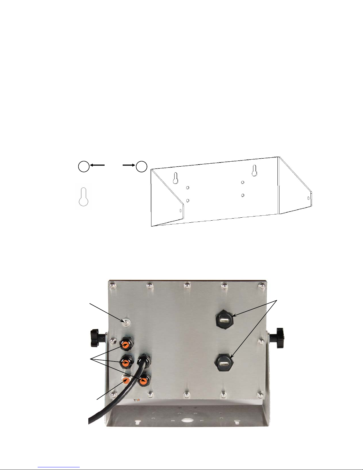
The Model 210 Indicator is housed in a Stainless Steel wall or desk-mount enclosure. The
gimbal may be mounted on a desktop or other smooth, flat, horizontal surface or may be
mounted on a wall. Refer to Figure No. 1 for a layout of wall-mounting bolts.
+
6.00"
+
Clearance for
#10 size screw
Figure No. 1
If wall mounted, make certain the mounting surface is strong enough to support the indicator.
The mounting location should be where the display is easily viewed while being close enough
to provide the operator easy access to the keypad. Carefully lay out the mounting hole
locations, then drill and install the anchor bolts. Attach the gimbal to the wall and securely
tighten the retaining bolts.
Calibration
Switch
Access
Optional
2XX-USBA
Connectors
Screw
I/O
(Serial,
Isolated
Inputs or
Outputs
and USB
Interface)
Load Cells
8200-M585-O1 Rev D 210 Installation & Technical 7
Figure No. 2
Page 14
INSTALLATION, CONT.
Load Cell Cable Connection for RFI Suppression
WARNING! Disconnect any external load cell power supply before
connecting load cells to the indicator. Failure to do so will result in
permanent damage to the indicator.
The load cell cable should be routed through the special metallic gland connector and the
shield wire must be connected to this gland connector for grounding and to eliminate RFI.
Refer to Figure No. 2 and Figure No. 3 for the appropriate gland connector.
1. Remove the 12 acorn nuts securing the back
panel to main housing.
2. Loosen and remove the metal gland
connector nut and remove the plastic insert.
3. Route the load cell cable through the nut and
plastic insert and into the enclosure.
4. With the load cell cable routed into the
enclosure, remove approximately 18 to 20
inches of the outer insulating jacket from the
cable exposing the internal wires.
5. Cut the shield wire so that it extends past the
outer jacket approximately 3/4 inch.
6. Remove 1/4" of insulation from the end of
each of the 4 wires (without sense leads) or 6
wires with sense leads (refer to figure No. 4).
7. Connect each of the wires to terminal block
P15 referring to labels on circuit board for
terminal connections. Refer to Figure No. 15
for terminal block location.
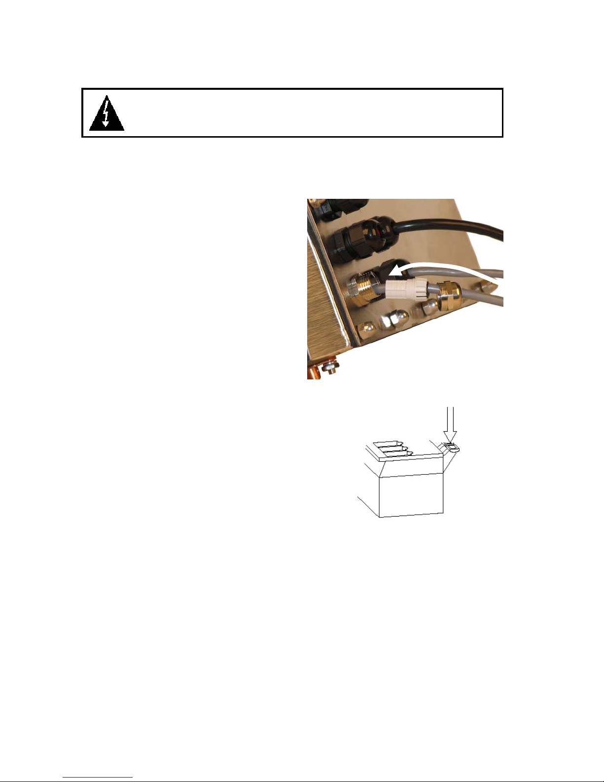
8. To terminate a wire, press down on release
bar for the terminal, insert wire into terminal
opening then allow release bar to return to its
original position, locking wire in place.
Repeat procedure until all wires are in place.
9. Route load cell cable wires through the two
cable clips provided on upper and left sides
of enclosure interior.
LOAD CELL TERMINAL BLOCK P15
TERMINAL NO. Function TERMINAL NO. Function
1 – +EXC + EXCITATION 5 – -SIG - SIGNAL
2 – +SEN + SENSE
6 – -SEN - SENSE
3 – +SIG + SIGNAL 7 – -EXC - EXCITATION
4 – SHLD SHIELD (Not used, load cell cable shield wire is connected to the
special metallic gland connector).
NOTE: If the sense leads are NOT used, you must install plug-in jumpers at J6 and J9
adjacent to the terminal block. These jumpers attach the sense leads to the excitation
leads. If sense leads ARE used (as in motor truck scales), these plug-in jumpers should be
positioned on one plug-in pin only or removed and stored for later use (see Figure No. 15).
Figure No. 3
Figure No. 4
8200-M585-O1 Rev D 210 Installation & Technical 8
Page 15

INSTALLATION, CONT.
Load Cell Cable Shield Wire Connection for RFI Suppression
1. After all terminations have been made,
remove the excess cable from the enclosure.
2. Referring to Figure No. 5, fold the shield wire
back over the plastic insert and then insert the
plastic insert (with the shield wire) into the
gland connector.
3. The shield wire is secured when tightening the
gland connector nut.
4. Do not over-tighten the connector but make
certain it is snug.
5. DO NOT USE TOOLS! Finger-tighten only!
Load Cell Cable Connection (Standard Gland Connector)
The following instructions describe the load cell connection should it be desired to route the
load cell cable through a standard gland connector.
1. Remove the 12 acorn nuts securing the back panel to main housing, and then loosen a
gland connector for the load cell cable. Refer to Figure No. 2 for illustration of connector
layout.
2. Slip the single cable from the load cell or load cell junction box through the gland connector
and into the enclosure.
3. Remove 3" of the outer insulation jacket then remove 1/4" of insulation from each of the 4
wires and shield (without sense leads) or 6 wires and shield (with sense leads). Refer to
Figure No. 4.
4. Connect each of the wires to terminal block P15 referring to labels on circuit board for
terminal connections. Refer to Figure No. 15 for terminal block location.
5. To terminate a wire, first press down on release bar for the terminal, insert wire into
terminal opening then allow release bar to return to its original position, locking wire in
place. Repeat procedure until all of wires are in place.
6. Route load cell cable through the two cable clips provided on upper and left sides of
enclosure interior.
LOAD CELL TERMINAL BLOCK P15
TERMINAL NO. Function TERMINAL NO. Function
1 – +EXC + EXCITATION 5 – -SIG - SIGNAL
2 – +SEN + SENSE
6 – -SEN - SENSE
3 – +SIG + SIGNAL 7 – -EXC - EXCITATION
4 – SHLD SHIELD (Connect the load cell cable shield wire here).
NOTE: If the sense leads are NOT used, you must install plug-in jumpers at J6 and J9
adjacent to the terminal block. These jumpers attach the sense leads to the excitation
leads. If sense leads ARE used (as in motor truck scales), these plug-in jumpers should be
positioned on one plug-in pin only or removed and stored for later use (see Figure No. 15).
Load Cell Connections with Over 30 Feet of Cable
For installations with over 30 feet of cable between the indicator and the load cells, sense
wires should be used. The sense wires must be connected between the +SENS, -SENS
terminals on the indicator and the +EXCITATION, -EXCITATION wires of the load cells or the
+SENS, -SENS terminals of the load cell trim board or the section seal trim board.
Figure No. 5
8200-M585-O1 Rev D 210 Installation & Technical 9
Page 16
INSTALLATION, CONT.
Serial I/O Cable Installation
The 210 indicator may be connected to a printer to record weight and associated data or it may
be connected to a remote display or to a computer for transmission of weight data. The weight
data may be transmitted on demand (pressing the PRINT key or on receipt of a command from
the computer). Refer to the Setup, SIO Serial I/O section of this manual.
1. Remove the 12 acorn nuts securing rear panel to main housing and then loosen a gland
connector for the serial cable. Refer to Figure No. 2 for illustration of connector layout.
2. Slip the serial cable through the gland connector and into the enclosure.
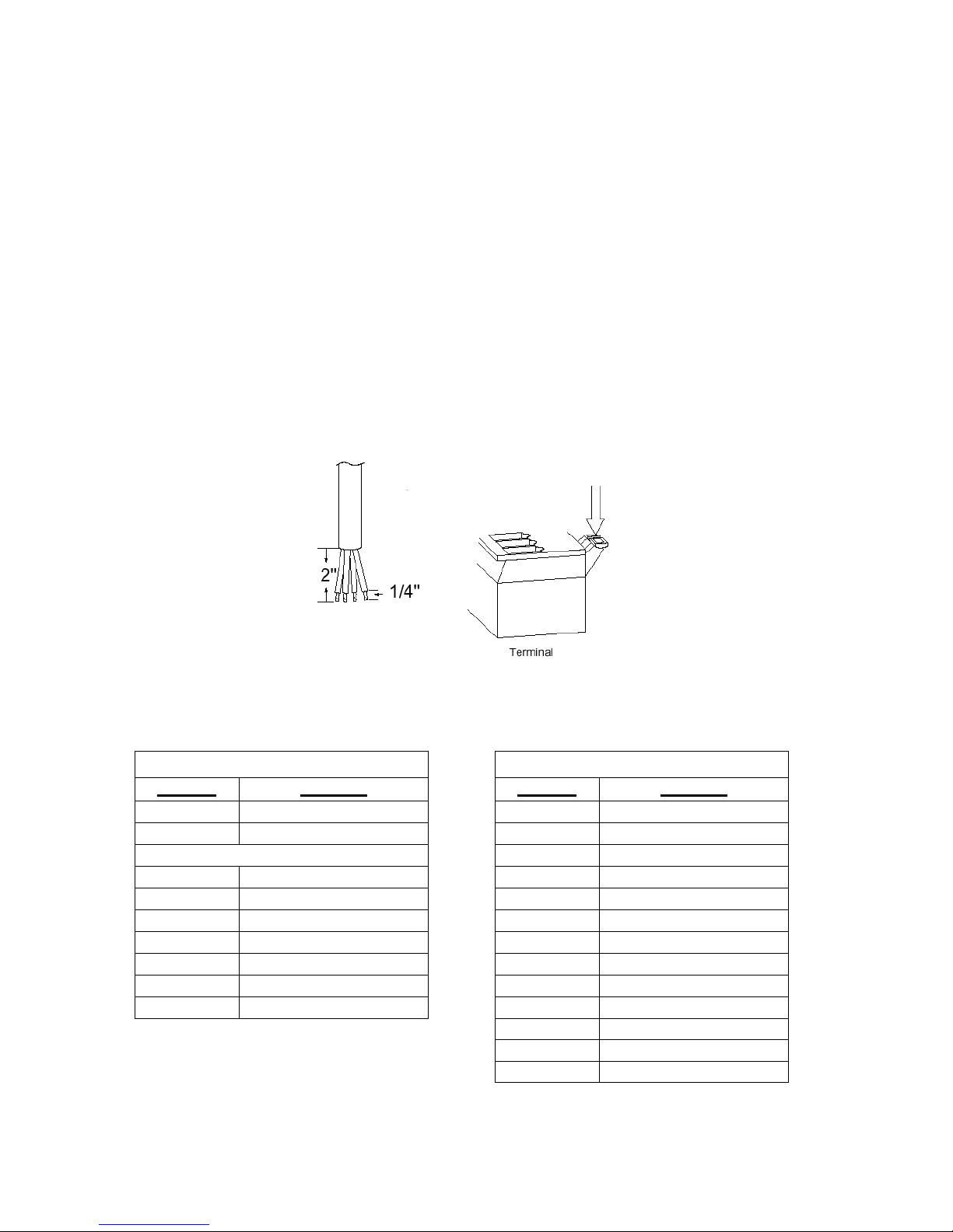
3. Remove 2" of the outer insulation jacket then remove 1/4" of insulation from each of the
wires (refer to the Figure No. 6).
4. Connect each of the wires to the Serial Data terminal block (P13 and P14) referring to
Figure No. 15 for terminal block locations.
5. To terminate, first press down on the release bar for the terminal, insert the wire into the
opening then allow the release bar to return to its original position, locking the wire in place.
Repeat the procedure until all of the wires are in place.
Figure No. 6
BI-DIRECTIONAL SERIAL INTERFACE
TERMINAL (P14) TERMINAL (P13)
PIN NO. Function PIN NO. Function
1
2
3
4 TxD2-RS232 4 RxD0-20mA-
5
6
7
8
9
11 TxD0-RS232
TxD1-RS232
RxD1-RS232
GND
RxD2-RS232
GND
TxD3-RS232
RxD3-RS232
GND
1
2
3
5
6
7
8
9
10
12
13
+20mA SRC
RxD0-SRC
RxD0-20mA+
TxD0-SRC
TxD0-20mA+
TxD0-20mA-
TxD1-20mA+
TxD1-20mA-
RxD0-RS232
GND
GND
8200-M585-O1 Rev D 210 Installation & Technical 10
Page 17
INSTALLATION, CONT.
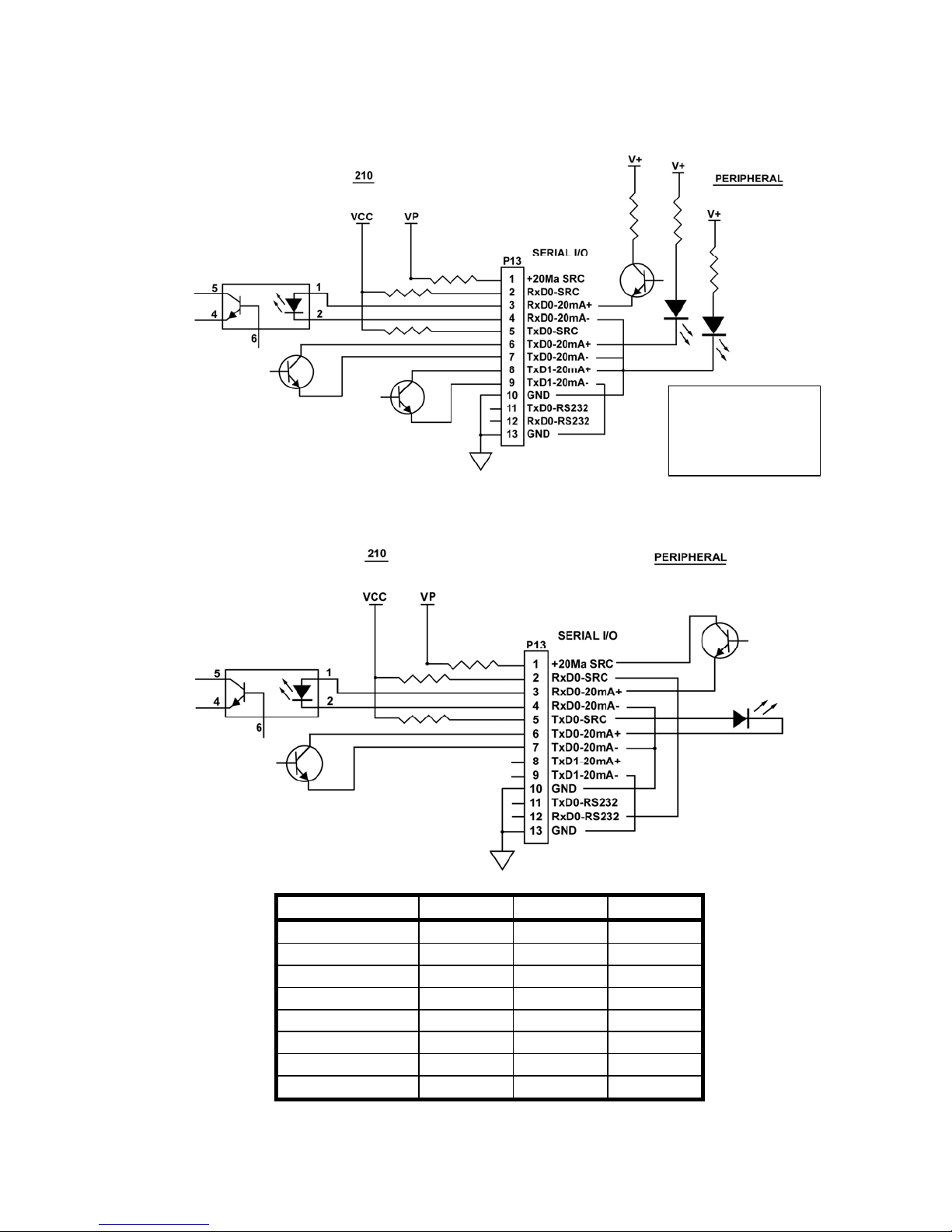
Interconnect Wiring for 20mA Current Loop Operation
Peripheral Device has ACTIVE END of Current Loop.
Figure No. 7
Interconnect Wiring for 20mA Current Loop Operation
Peripheral Device has PASSIVE END of Current Loop.
IMPORTANT!
A jumper MUST be
installed between P13
terminals 5 & 12 to
enable RxD0-20mA.
Figure No. 8
TXD0
RXD0
TXD1
RXD1
TXD2 X
RXD2
TXD3
RXD3
* Mutually exclusive
** Mutually exclusive
8200-M585-O1 Rev D 210 Installation & Technical 11
PORT RS-232 20mA USB
X X
X X
X X
X
X
*X *X
**X **X
Page 18
INSTALLATION, CONT.
USB Interface
The 210 indicator USB Interface is a standard full speed (12Mbps) USB 2.0 device port. It can
be connected to a USB 2.0 host, with the Cardinal Scale 8200-B163-0A USB CABLE or a
industry standard USB 2.0 cable, to be used as the COM3 serial I/O port set to 8 bit data, 1
stop bit, no parity, 9600 to 115.2k baud. Refer to the Setup, SIO Serial I/O section of this
manual.
The USB port is enabled with jumpers J4 and J5 (see Figure No. 15) set to the USB position
(utilizing the indicator COM3 serial port) and the USB PWR jumper, J10 (see Figure No. 15),
set to the BUS position to be powered by the USB host or to the VCC position to be powered
by the 210 indicator main PC board. Follow the “Driver Installation Instructions for Indicator’s
USB Port” in conjunction with the usb2ser.inf file located on the 210 Indicator Installation and
Technical Manual CD.
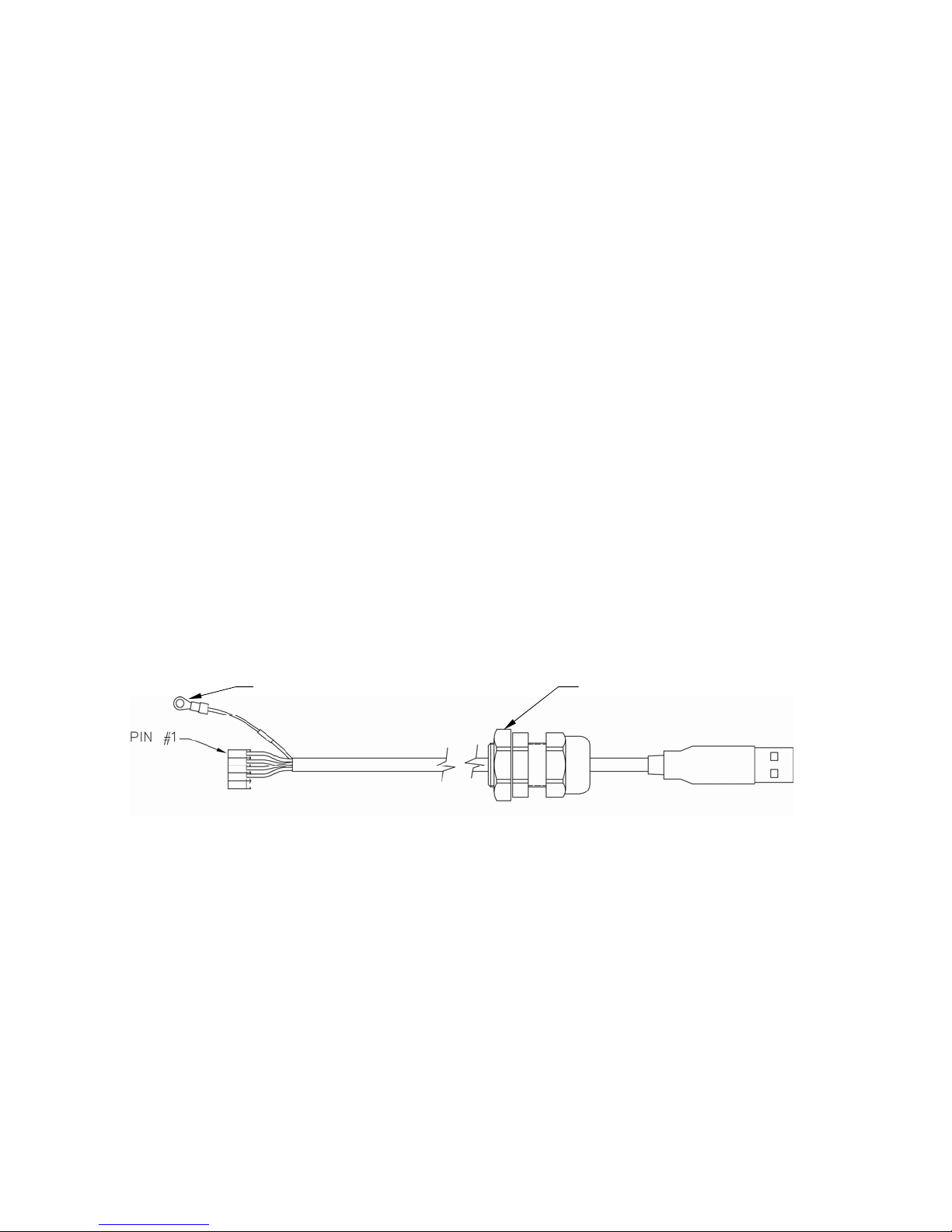
8200-B163-0A Water Tight USB Cable Installation
1. Remove the 12 acorn nuts securing the back panel to main housing.
2. Remove a gland connector from the back panel. Refer to Figure No. 2 for illustration of
connector layout.
3. Loosen the gland connector nut from the 8200-B163-0A cable/gland assembly (see
Figure No. 9) and slip off over the 5-pin cable connector and ground wire.
4. Insert the 5-pin connector and ground wire through the rear panel.
5. Slip the gland connector nut back over the 5-pin connector and ground wire and tighten on
the gland connector on the rear panel.
6. Pull the USB cable through the gland to reach P4, the USB-B header.
7. Plug the USB cable connector onto the USB-B, P4 header, referring to Figure No. 15 for
the location of P4. Tighten the gland cable nut on the USB cable.
GROUND WIRE REMOVE THIS NUT
Figure No. 9
8. To attach the ground wire (see Figure No. 9); remove a 6-32 nut and washer from the
corner of the main board.
9. Connect the ground wire from the USB cable by placing the ring terminal over the 6-32
threaded stud.
10. Reinstall the washer and 6-32 nut and tighten.
Standard USB Cable Installation
1. Remove the 12 acorn nuts securing the back panel to main housing.
2. Remove a gland connector from the back panel. Refer to Figure No. 2 for illustration of
connector layout.
3. Slip the cable through the hole in the rear panel and into the enclosure.
4. Plug the USB cable into the USB-B connector P6. See Figure No. 15 for the location of P6.
8200-M585-O1 Rev D 210 Installation & Technical 12
Page 19
INSTALLATION, CONT.
Main PC Board I/O Functions Table
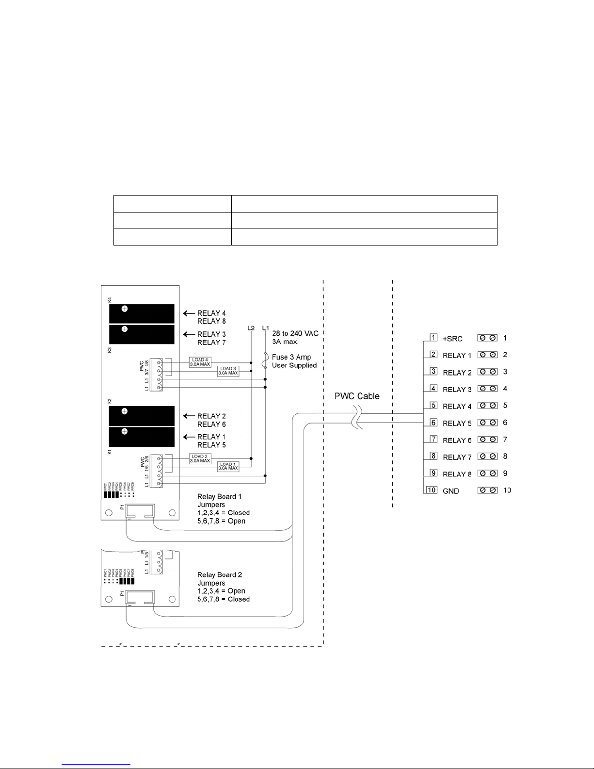
Refer to Figure No. 10 for the AC Input Relay board, Figure No. 11 for the AC Output Relay
board, Figure No. 13 for the RB4C Relay board and Figure No. 15 for the Main PCB.
INPUTS
PWC CHECKWEIGHER DFC
P3 FUNCTION P2 Presets Check 3 Fill 1 Fill 2
2 GROSS/NET 2 PWC 1 UNDER Fill Fast
3 PRINT 3 PWC 2 ACCEPT Slow
4 ZERO 4 PWC 3 OVER Dump
5 TARE 5 PWC 4
6
7 UNITS 7 PWC 6
8 START 8 PWC 7
9 STOP 9 PWC 8
6 PWC 5
OUTPUTS
RB4/RB8 Relay Box Cable Wire Number to Relay Number Table
The relay box cable wire numbers correspond to the indicator main PC board remote input
(P3) and output (P2) terminal connection pins.
CABLE WIRE
NUMBER
1 +SRC (For AC Input Relays) 6 5
2 1 7 6
3 2 8 7
4 3 9 8
5 4 10 GND
RELAY NUMBER
(Set Proper Jumpers)
CABLE WIRE
NUMBER
RELAY NUMBER
(Set Proper Jumpers)
8200-M585-O1 Rev D 210 Installation & Technical 13
Page 20
INSTALLATION, CONT.
Optically Isolated Remote Inputs
Included with the I/O are 4 programmable inputs that may be used to remotely (up to 100 feet)
initiate various functions within the indicator. These inputs are accessed via a terminal block
(P3) on the back of the PC board (see Figure No. 15). The 8 inputs are defined as follows:
TERMINAL NO.
1 SRC 12-24VDC
2 Gross
3 Print
4 Zero
5 Tare
6 *
7 UNITS
8 START
9 STOP
10 GND
NOTE: The input must be momentarily connected to GND to initiate the function.
AC Input Relay Board(s)
The AC Input Relay Board(s) are mounted in an external junction box for use with the 210
Indicator. The RB4-ACIN (115 VAC) or RB4-ACINV (230 VAC) contain one board and
supports 4 inputs (jumper selectable). The RB8-ACIN (115 VAC) or RB8-ACINV (230 VAC)
contain two boards and supports eight inputs that are jumper selectable. The relay board used
in the 115 VAC versions is Cardinal p/n 8200-C324-0A. The 230 VAC version uses relay
board Cardinal p/n 8200-C324-1A. Connect the devices as shown in Figure No. 10.
INPUT RELAY TYPE IAC-5 90 to 140 VAC @ 6mA maximum for each plug-in relay
Function
INPUT RELAY TYPE IAC-5A 180 to 280 VAC @ 6mA maximum for each plug-in relay
OUTPUT 5VDC @ 12mA from the 210 main pc board assembly P3
12VDC @ 12mA maximum from external source
CONNECTION Removable plug-in screw terminals for up to 14 AWG wire
8200-M585-O1 Rev D 210 Installation & Technical 14
Page 21
INSTALLATION, CONT.
AC Input Relay Board(s), Cont.
210 Indicator – P3
225 Indicator – P17
Relay Box Assembly RB4-ACIN or RB8-ACIN
Relay Box Assembly RB4-ACINV or RB8-ACINV
Relay Box Assembly RB4-ACIN or RB8-ACIN
IMPORTANT! AC INPUT RELAYS ARE VOLTAGE DEPENDENT. A DIFFERENT
RELAY IS REQUIRED FOR 115 VAC AND 230 VAC!
Figure No. 10
Figure No. 8
Figure No. 5
8200-M585-O1 Rev D 210 Installation & Technical 15
Page 22

INSTALLATION, CONT.
Preset Weight Comparator/Checkweigher Logic Level Output
If you so choose, you may use the logic level outputs from your Model 210 indicator’s preset
weight comparators or checkweigher to control peripheral devices used to manage the flow of
material or signal when the weight is within preset limits. Note that these outputs are at logic
level and cannot drive external devices directly, with the exception of the Cardinal 2XX-OU
Checkweigher Light Bar. Solid-state relays can be used to accept the logic level output from
the 210 and in turn, drive other external devices.
J7 (VP/VCC) - REMOTE OUT SRC (SOURCE) JUMPER
The Remote Output SRC jumper J7, when connected, allows the 210 indicator to supply
(source) VP (15VDC) or VCC (5vdc) to a solid-state relay or other load of 200 ohms or greater.
The positive connection from the relays must be connected to the PWC connector pins and the
negative wire from the relays to the GND pin. See Figure No. 15 for jumper and REMOTE
OUTPUTS connector location.
For completely isolated outputs, J7 must be open (positioned on one plug-in pin only or
removed) and the user must provide 12 to 24 VDC to the SRC pin and a ground return to the
load. The load must still be 200 ohms or greater.
To connect the control cable to the preset weight comparator/checkweigher logic level output
connector P2:
1. If the rear panel of the indicator has been removed, proceed to step 2. Otherwise, remove
the 12 acorn nuts securing the rear panel to main housing
2. Loosen the gland connector for the cable. Refer to Figure No. 2 for the gland connector
layout.
3. Slip the cable through the gland connector and into the enclosure.
4. Remove 2 inches of the outer insulation jacket
5. Next, remove 1/4 inch of insulation from each of the wires.
6. Connect each of the wires to the REMOTE OUTPUTS terminal block (P10) referring to
Figure No. 15 for terminal block locations.
7. To terminate a wire, use a small flat blade screwdriver and press down on the release bar
for the terminal. Insert the wire into the terminal opening. Remove the screwdriver,
allowing the release bar to return to its original position, locking the wire in place.
8. Repeat procedure until all wires are in place.
8200-M585-O1 Rev D 210 Installation & Technical 16
Page 23
INSTALLATION, CONT.
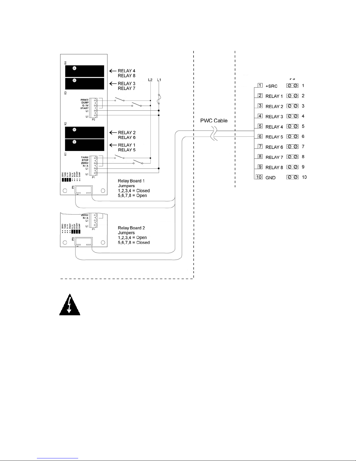
AC Output Relay Board(s)
The AC Output Relay Boards are mounted in an external junction box for use with the 210
Indicator and can be purchased from Cardinal. The RB4-ACOUT contains one board and
supports four outputs (jumper selectable). The RB8-ACOUT contains two boards and
supports eight outputs. The relay board used in both is (Cardinal p/n 8539-C062-0A).
Connect the devices to be controlled as shown in Figure No. 11.
The individual relays can be configured to be on (closed) or off (open) at weights under the
preset weight then switch at the preset weight from on-to-off or off-to-on by setting the under
weight condition to on or off during setup and calibration or setup review.
OUTPUT (closed) 28-240VAC @ 3A maximum for each plug-in relay
CONTROL INPUT 5VDC @ 12mA from the 210 main pc board assembly P2
CONNECTION Removable plug-in screw terminals for up to 14 AWG wire
NOTE: All relays are the normally-open type that will open when power to the indicator is lost.
210 Indicator – P2
Relay Box Assembly RB4-ACOUT or RB8-ACOUT
8200-M585-O1 Rev D 210 Installation & Technical 17
Figure No. 11
Page 24
INSTALLATION, CONT.
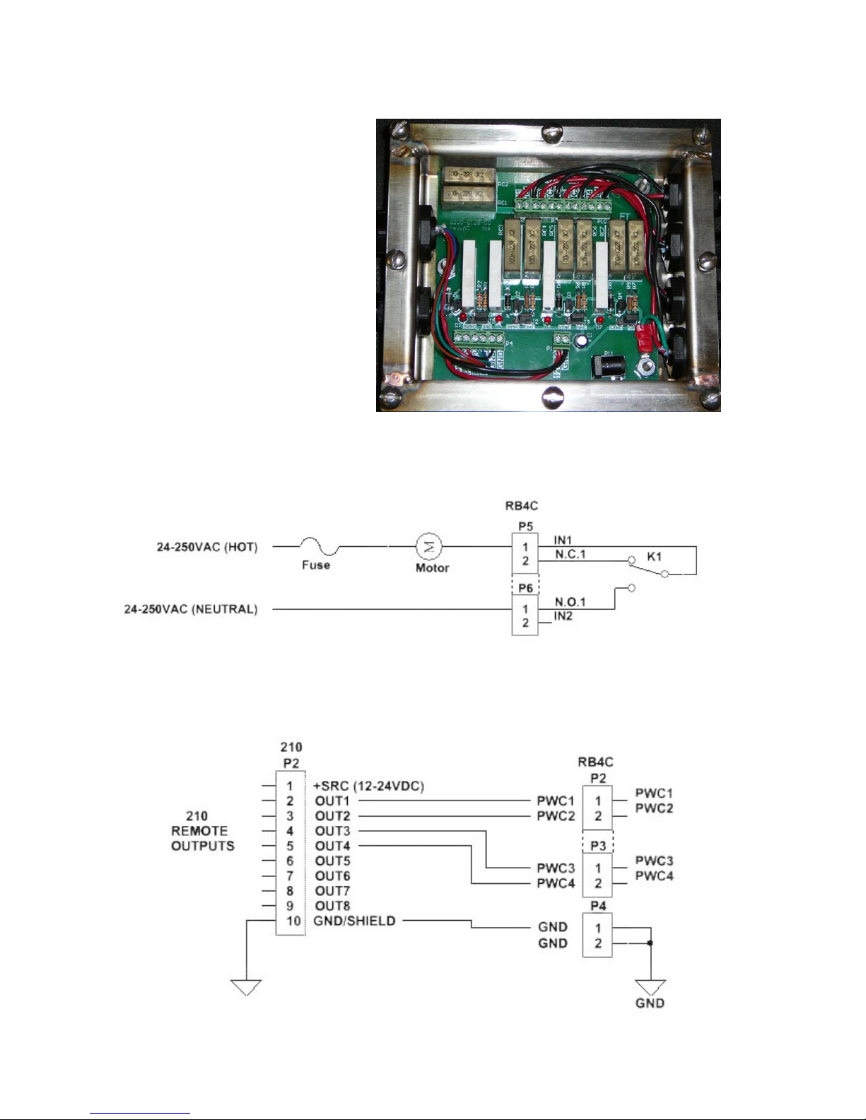
RB4C Relay J-BOX
The RB4C provides four FORM-C,
SPDT (one normally open and one
normally closed), 24-250 volt (AC or
DC), 3A mechanical relays to control
external devices from a digital weight
indicator equipped with output control.
The output control can be 5-15VDC,
1mA source or 20mA current sink.
The source (SRC) or sink (SINK) type
is selected with the Relay Control
Source Type Jumpers, J1, J2, J3, and
J4 (see Figure No. 12), one for each
relay.
RB4C Output Relay Wiring Example
J1
J2
J3
J4
Figure No. 12
(Relay Control Source Type Jumpers)
Figure No. 13
RB4C Control Circuit Wiring Example
Figure No. 14
8200-M585-O1 Rev D 210 Installation & Technical 18
Page 25
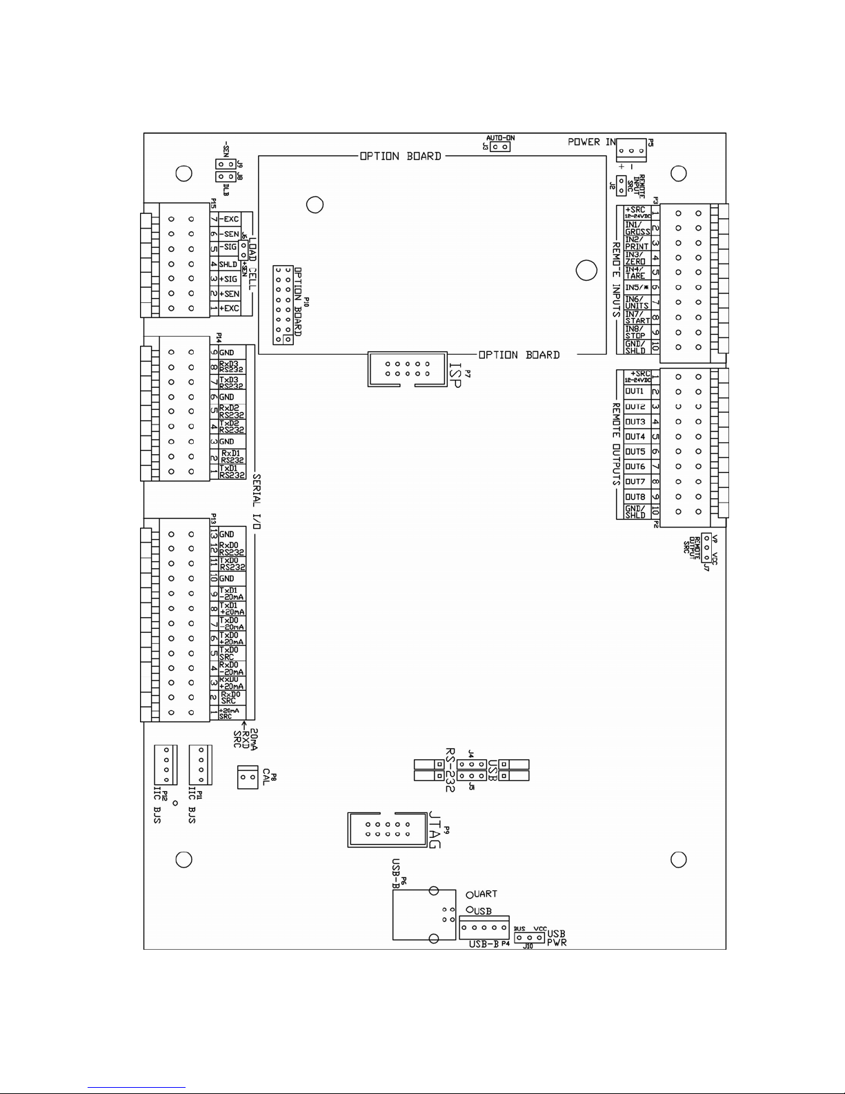
Main PCB
INSTALLATION, CONT.
8200-M585-O1 Rev D 210 Installation & Technical 19
Figure No. 15
Page 26

INSTALLATION, CONT.
Main PCB Jumpers
J2 – REMOTE INPUT SRC (SOURCE)
The Remote Input SRC jumper J2, when connected, allows the 210 indicator to supply
(source) 12-24VDC to a solid-state relay or other load of 200 ohms or greater. The positive
connection from the relays must be connected to the remote input connector pins and the
negative wire from the relays to the GND/SHLD pin.
J3 – AUTO-ON JUMPER
The AUTO-ON jumper J3, when connected, will cause the indicator to power on automatically
whenever power is applied to the power input connector. If power is lost momentarily and then
reapplied, the indicator will turn on without pressing the ON/OFF key.
J4 AND J5 – RS-232/USB PORT
These jumpers control whether COM3 is RS-232 and uses Serial I/O P14 (pins 7, 8, & 9) or
USB and uses the USB-B header, P4 or USB-B port, P6.
J6 (+SEN) AND J9 (-SEN) – SENSE JUMPERS
If the sense leads are NOT used, you must install plug-in jumpers at J6 and J9 adjacent to the
terminal block. These jumpers attach the sense leads to the excitation leads. If sense leads
ARE used (as in motor truck scales), these plug-in jumpers should be positioned on one plugin pin only or removed and stored for later use.
J8 – DLB (DEAD LOAD BOOST JUMPER)
For very low dead loads (less than 10% of the combined load cell capacity) connect the dead
load boost jumper J8 on the printed circuit board.
J7 – REMOTE OUTPUT SRC (SOURCE)
The Remote Output SRC jumper J7, when connected, allows the 210 indicator to supply
(source) VP (15VDC) or VCC (5vdc) to a solid-state relay or other load of 200 ohms or greater.
The positive connection from the relays must be connected to the remote output connector
pins and the negative wire from the relays to the GND/SHLD pin.
J10 – USB PWR
The USB PWR jumper J10, selects whether the USB power is provided by the USB Host (set
to BUS position) or by the 210 indicator (set to VCC position).
Re-Installing the Rear Panel
After all terminations have been made;
1. Remove the excess cable from the instrument enclosure and securely tighten each of
the cable gland connectors.
Do not over-tighten these connectors but make certain they are snug.
DO NOT USE TOOLS! Finger-tighten only!
2. Ensure any unused gland connectors are plugged and replace the rear panel.
3. Secure the rear panel with the 12 acorn nuts removed earlier.
4. Follow a diagonal pattern when tightening the acorn nuts.
8200-M585-O1 Rev D 210 Installation & Technical 20
Page 27
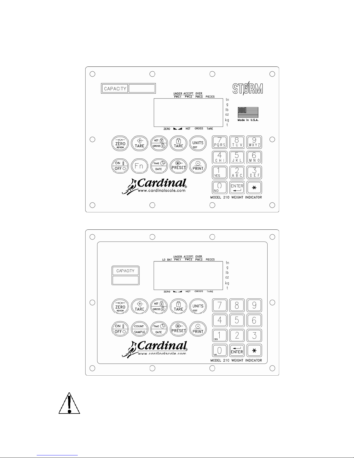
KEYPAD FUNCTIONS
The Model 210 is equipped with a 22-key keypad. The keypad is used to enter commands
and data into the indicator. This section describes each key along with its normal function. It is
helpful to refer to the actual indicator while reading this section.
Figure No. 16 (Updated Keypad)
Figure No. 17 (Legacy Keypad)
DO NOT operate the keypad with pointed objects (pencils, pens, etc).
Damage to keypad resulting from this practice is NOT covered under warranty.
8200-M585-O1 Rev D 210 Installation & Technical 21
Page 28

KEYPAD FUNCTIONS, CONT.
ZERO/REVIEW KEY
This key performs two functions. In normal operation, pressing this key will cause an
immediate zeroing of the weight display up to the selected limit of 4% or 100% of the scale’s
capacity. Note that this selection is made during the setup and calibration of the indicator.
Pressing this key after the key will enter the Review mode of Setup and Calibration. Refer
to description of key and the Setup Review section of this manual for details.
TARE KEY (with diamond "T" symbol)
This is a dual function key. Pressing the TARE key alone (Pushbutton Tare mode) will store
the current gross weight as a new tare weight and cause the weight display to change to the
net weight display mode (Net annunciator turns on). Pressing it key after entering a numeric
value (Keypad Tare) will cause the value entered to be accepted as a new tare weight.
NOTE: Tare weights equal to or greater than scale capacity cannot be entered. In addition,
keypad tare weight division value must be same as scale division value. For example, a unit
with .005 lb as division value will display Error if you enter 1.003 for tare weight.
NET/GROSS KEY
This key is used to toggle between Net and Gross weight modes. The selected mode is
indicated by turning on the appropriate annunciator on the display. Note that if no valid tare
weight has been entered, pressing this key will cause a momentary “notArE” display error
and the indicator will remain in the Gross weight mode.
TARE KEY (with weight "T" symbol)
Pressing this key will display the current tare weight for three seconds.
UNITS/TEST KEY
This key performs two functions. In normal operation, it is used to select the units in which
the weight is to be displayed. The available units of measure ("unit1" and "unit2") are
enabled or disabled in setup. The available units include tons, pounds only, pound-ounces,
ounces only, tonnes (metric tons), kilograms, and grams. Note that not all combinations are
supported. Pressing this key after the key will enter the Test mode. The Test mode is
used to conduct a test of all display elements. Refer to description of key for details.
ON/OFF KEY
This key performs two functions. Pressing it when the indicator is off will apply power to the
indicator. If the indicator is already on, pressing this key will turn the indicator off.
Fn KEY (Legacy COUNT/SAMPLE Key)
This key is used to perform numerous functions. Note that the various functions of this key
are dependent upon the selected Mode of Operation setting. Those functions are as follows:
oPEr= 0 Normal Scale Operation
This key performs two functions. The first time it is pressed, the indicator will count (unless
piece weight is 0). The second time it is pressed (or if pct=0 on the first press) will show
the prompt ADD=5 on the display. Continued pressing of the Fn key will toggle between the
ADD=5, 10, 25, 50, 75 prompts to select a sample size. When desired sample size is
displayed, press the ENTER key OR with ADD= (5, 10 etc.) displayed, using the numeric
keypad, key-in any desired sample value, then press the ENTER key. Press the key to
abort the input operation. To exit the count function and display weight, press the
NET/GROSS key.
8200-M585-O1 Rev D 210 Installation & Technical 22
Page 29

KEYPAD FUNCTIONS, CONT.
oPEr= 1 ID Storage
This key initiates a weigh-in or weigh-out operation.
Press the Fn key and enter the ID at the id= prompt. To store/modify a permanent ID,
press the key followed by the Fn key, then enter the desired ID at the id= prompt.
oPEr= 2 Digital Fill Control
This key will start or pause a digital fill.
1. With the DFC in an idle state, press the Fn key to start the fill.
2. While filling, press the Fn key to pause the fill.
3. While paused, press the Fn key to resume or abort the fill. The indicator will prompt
whether or not to continue filling (cont= yes/no).
If the DFC is setup for manual dumping, press the Fn key to initiate a dump after a fill is
completed.
oPEr= 6 Livestock Weig he r
This key will allow you to input a head count (CoUnt=) for the next ticket to be printed.
Once prompted, press the ENTER key to display the current head count. Use the numeric
keys to select the new head count (1-255) and then press the ENTER key to accept it. The
value you entered will appear on the next ticket that is printed.
TIME/DATE KEY
This key is used to enter the clock mode to program the time, date and consecutive number.
Pressing the TIME/DATE key will enter the clock mode with the 210 displaying HoUr=.
12-Hour Format Selected In Setup (td=12)
1. With the display showing HoUr=, press the ENTER key.
2. If the time displayed is correct, press the ENTER key and proceed to step 4.
3. If the displayed time is incorrect, use the numeric keys to enter the correct time and
press the ENTER key.
4. The display will change to A=. Press the ENTER key.
5. The display will show YES.
If the time is before noon (12:00 PM), press the ENTER key.
If the time is after noon (12:00 PM), press the 0/NO key, then press the ENTER key.
6. The display will show dAtE=. Press the ENTER key.
7. If the date displayed is correct, press the ENTER key to proceed to the consecutive
number prompt, CnC n=.
8. If the date displayed is incorrect, use the numeric keys to enter the correct date and
press the ENTER key to proceed to the consecutive number prompt. Remember to
enter the date in the same format (month-day-year or day-month-year) as selected by
the USA setup parameter. Note that with the USA=YES setting, the date format is
month-day-year.
8200-M585-O1 Rev D 210 Installation & Technical 23
Page 30

KEYPAD FUNCTIONS, CONT.
24-Hour Format Selected In Setup (td=24)
1. With the display showing HoUr=, press the ENTER key.
2. If the time displayed is correct, press the ENTER key and proceed to step 4.
3. If the displayed time is incorrect, use the numeric keys to enter the correct time and
press the ENTER key. Note that with the 24-hour format selected, entering all times
after noon (12:00 PM), you must add 12 to the time, i.e. 3 PM would be 1500.
4. The display will show dAtE=. Press the ENTER key.
5. If the date displayed is correct, press the ENTER key to proceed to the consecutive
number prompt, CnC n=.
6. If the date displayed is incorrect, use the numeric keys to enter the correct date and
press the ENTER key to proceed to the consecutive number prompt. Remember to
enter the date in the same format (month-day-year or day-month-year) as selected by
the USA setup parameter. Note that with the USA=YES setting, the date format is
month-day-year.
Consecutive Number
Consecutive Number is a printable number (see PRINT TABS in SETUP AND
CALIBRATION section) corresponding to the number of consecutive weighments that have
been printed. The consecutive number is incremented (if not set to “0”) every time a weight
is printed. The consecutive number will be reset to the number entered at the CnC n=
prompt.
If the consecutive number displayed is correct, press the ENTER key to resume normal
operation. If the consecutive number displayed is incorrect, use the numeric keys to enter
the correct consecutive number (up to 6 digits) and press the ENTER key to resume normal
operation.
PRESET KEY
This key is used to perform numerous functions. Note that the various functions of this key
are dependent upon the selected Mode of Operation setting. Those functions are as follows:
ID Storage (oPER=1)
If the setup parameter ALAr? is YES, the ALrRt prompt will be displayed. Press the
ENTER key and the alarm weight value will be displayed. If the value is acceptable, press
the ENTER key, otherwise, use the numeric keys to enter the new alarm weight value and
press the ENTER key.
The ALrti prompt will be displayed, press the ENTER to display the number of seconds
that the alarm output (PWC1) is to be turned on when the scale weight exceeds the alarm
weight. The alarm time can be from 0 to 99 seconds.
8200-M585-O1 Rev D 210 Installation & Technical 24
Page 31

KEYPAD FUNCTIONS, CONT.
Digital Fill Control (oPER=2)
If Stor is enabled (Stor=YES), you will first be prompted for the stored preset ID
(Stor=). Press the ENTER key to see the current ID. If it is correct then press the ENTER
key, otherwise enter the desired stored preset ID to be recalled from memory and press the
ENTER key.
Single Speed operation: (SPEED=1)
The FiLL= prompt is displayed, press the ENTER key. The fill weight value is displayed, if
the value is acceptable, press the ENTER key, otherwise, use the numeric keys to enter the
new fill weight value and press the ENTER key.
The Trin= prompt is displayed, press the ENTER key. The trim weight value is displayed,
if the value is acceptable, press the ENTER key, otherwise, use the numeric keys to enter
the new trim weight value and press the ENTER key.
Two Speed operation: (SPEED=2)
The FASt= prompt is displayed, press the ENTER key. The fast weight value is displayed,
if the value is acceptable, press the ENTER key, otherwise, use the numeric keys to enter
the new fast weight value and press the ENTER key.
The SLo= prompt is displayed, press the ENTER key. The slow weight value is displayed, if
the value is acceptable, press the ENTER key, otherwise, use the numeric keys to enter the
new slow weight value and press the ENTER key.
The Trin= prompt is displayed, press the ENTER key. The trim weight value is displayed,
if the value is acceptable, press the ENTER key, otherwise, use the numeric keys to enter
the new trim weight value and press the ENTER key.
If the GATE sequence is set to 3 (chatter-gate), the Ct on= prompt will be displayed; press
the ENTER key. The chatter-gate on time is displayed, if the value is acceptable, press the
ENTER key, otherwise, use the numeric keys to enter the new chatter-gate time and press
the ENTER key.
If Stor is enabled (Stor=YES), you can store/modify a permanently stored preset ID by
pressing the key followed by the PRESET key, then enter the desired stored preset ID
tor=?) then press the ENTER key.
(S
Preset Weight Comparator (oPEr=3)
If the Preset Weight Comparator mode of operation (oPEr =3) was selected, the PSEt1=
prompt will be displayed. Press the ENTER key and the currently stored weight value for
PRESET #1 will be displayed. If the value displayed is acceptable, pres the ENTER key,
otherwise, use the numeric keys to enter the new preset value and press the ENTER key.
The setup parameter oPEr=3, p out=, determines the number of preset weight
comparators that will be displayed and prompted for.
There can be up to 8 Preset weight comparators.
8200-M585-O1 Rev D 210 Installation & Technical 25
Page 32

KEYPAD FUNCTIONS, CONT.
Checkweigher (oPEr=4)
If the Checkweigher feature was selected and the PRESET key pressed, the ACCEPT and
UNDER annunciators will flash and the preset value for the minimum acceptable weight will
be displayed. Press the ENTER key if the displayed value is correct or use the numeric
keys and enter the new value and press the ENTER key. The ACCEPT and OVER
annunciators will now flash and the display will show the minimum value of weight over the
accepted range. As before, if the value shown is correct, press the ENTER key. If the value
is incorrect, enter the new value and press the ENTER key to save it. Note that this value
must be greater than the accept value. Remember that both the preset weight comparators
and checkweigher functions operate on the absolute value of weight ignoring the polarity.
After the second preset value is entered, the indicator will return to normal operation.
PRINT KEY
Pressing this key will initiate the transmission of weight and other data via the selected printer
output port (see Port= under Print menu). The first gross or net weight printed after the
gross weight has returned to “zero” will be added to the associated accumulator, and the
consecutive number will be incremented.
If the id= (ID Prompt) has been enabled during setup, when the PRINT key is pressed, the
indicator will prompt for an ID to be printed on the ticket.
If the A clr= is set to 1 (Yes), input up to 6 digits for the ID and then press the ENTER key
to complete the transaction. Upon pressing the ENTER key, the print function will occur.
If the A clr= is set to 0 (no), press the ENTER key to display the current ID. If ID
displayed is acceptable, press the ENTER key again to complete transaction. Otherwise,
input up to 6 digits for ID then press the ENTER key to complete the transaction. The print
function will occur after the ENTER key is pressed.
Note that the indicator will not respond to the Print command unless the weight display is
stable. If displaying gross weight, the only weight printed is gross weight. If displaying net
weight, the gross, tare, and net weights are printed.
The 210 includes support for visual tickets. Visual
tickets are designed by the PC based programs
Visual Print or nControl, then downloaded to the
indicator. Two programmable formats in addition to
the standard print tab settings are allowed.
Print formats are selected by using the and PRINT
keys in combination (refer to the key, and
PRINT key section for details).
NOTE: When the PRINT key is pressed, the
indicator looks for the selected format. If a visual
ticket is not found it reverts to the print tab settings.
#2
10:19 12/13/2012
100.00 lb G
20.00 lb T
80.00 lb N
0.00 lb GROSS ACCUM
272.00 lb NET ACCUM
TICKET EXAMPLE
8200-M585-O1 Rev D 210 Installation & Technical 26
Page 33

KEYPAD FUNCTIONS, CONT.
0 THROUGH 9, A THROUGH Z KEYS
These keys are used to enter alphanumeric data during the
setup and calibration as well as during normal operation of the
indicator.
NOTE: The 1 and 0 keys have dual functions. They are used to
enter numeric data during setup and calibration as well as
during normal operations and are also used to answer yes (1 =
YES) or no (0 = NO) to various prompts.
Where allowed, (ID entry), letters
key in succession until the desired letter is displayed. This is
similar to the way a cell phone keypad operates. (Ex: If you
want to enter the letter C, you would need to press the 2 key
four times).
A special seven segment font is used for the display of the letters as follows:
A, a; B, b C, c D, d E, e F, f G, g H, h I, i J, j
are entered by pressing the
K, k L, l M, m N, n O, o P, p Q, q R, r S, s, T, t U, u V, v W, w X, x Y, y Z, z
ENTER KEY
This key serves two purposes. First, when reviewing setup parameters, pressing the ENTER
key will display the current setting of the parameter. Second, the ENTER key is used to
signal completion of the entry of data and causes the indicator to process the data entered.
8200-M585-O1 Rev D 210 Installation & Technical 27
Page 34

KEYPAD FUNCTIONS, CONT.
(ASTERISK) KEY
This key is used for several functions. During Setup, when a setup parameter (not a
parameter value) is displayed, pressing it key will "backup" to the previous prompt.
In normal operation, pressing the key will display FUnCt=. Pressing the associated key
listed below will enable additional features. These features and their associated key
combinations are as follows:
AND ZERO/REVIEW KEY
This combination will enter the Review mode of Setup and Calibration. Refer to
Setup Review section of this manual for details.
AND NET/GROSS KEY
This combination will display the Net accumulator.
AND NET/GROSS KEY, PRINT KEY
This combination will print the Net accumulator.
AND NET/GROSS KEY, ZERO KEY
This combination will zero (clear) the Net accumulator.
AND NET/GROSS KEY, NET/GROSS KEY
This combination will display the Gross accumulator.
AND NET/GROSS KEY, NET/GROSS KEY, PRINT KEY
This combination will print the Gross accumulator.
AND NET/GROSS KEY, NET/GROSS KEY, ZERO KEY
This combination will zero (clear) the Gross accumulator.
AND UNITS KEY
This combination will enter the Test mode. The Test mode is used to test of all the
display elements. It consists of five (5) cycles, each lasting about one (1) second:
1. All horizontal segments will turn on (no annunciators).
2. All vertical segments and decimal points will turn on (no annunciators).
3. All annunciators will turn on.
4. All display elements off.
5. The model number (210) and the software version X.X.
6. The calibration numbers (C1 to C4).
AND PRINT KEY
This combination is used to change the selected print ticket format. Pressing the
key then the PRINT key will display a prompt “Prt=”. Press the ENTER key to show
the current value. If the setting displayed is acceptable, press the ENTER key again
to save it. Otherwise, using the numeric keys enter the new setting, then press the
ENTER key to save it. Allowable values are:
0 = print tab settings 1 = visual ticket format 1 2 = visual ticket format 2
In addition to using the key, PRINT key combination to change the print ticket
format, the operator (just prior to printing the ticket) can change the print ticket format
at the end of the weighing operation. This is accomplished by performing the normal
weighing operation, then pressing the desired format number (0, 1 or 2), followed by
pressing the PRINT key.
NOTE: When a print format is selected (by either method), it will remain active
until changed by the operator.
8200-M585-O1 Rev D 210 Installation & Technical 28
Page 35

ANNUNCIATORS
Annunciators are turned on to indicate that the display is in the mode corresponding to the
annunciator label or that the status indicated by the label is active. The annunciators flash on
and off to indicate that the indicator is waiting for input from the keypad for the mode indicated
by the flashing annunciator. Refer to Figure No.10 for location of the annunciators.
ZERO
This annunciator is turned on to indicate that the weight displayed is within +/- 1/4 division of
the center of zero.
(STABLE)
This annunciator is turned on when the weight display is stable. When off, it means that the
change in successive weight samples is greater than the motion limits selected during setup.
NET
This annunciator is turned on to show that the displayed weight is the net weight (gross
weight less tare weight).
GROSS
This annunciator is turned on to show that gross weight is displayed. Gross weight will be
displayed when no tare weight is stored.
TARE
This annunciator is turned on to show that the displayed weight is the tare weight.
UNDER/PWC1
This annunciator is used to signal that the displayed weight is less than the minimum value of
acceptable weight used in the Checkweigher feature. Note that this annunciator is active
only when the Checkweigher feature is enabled.
The PWC1 annunciator is turned on to indicate that the displayed weight is equal to or
greater than the weight value stored as preset number 1. Note that this annunciator is active
only when the Preset Weight Comparator feature has been enabled.
ACCEPT/PWC2
This annunciator is used to signal that the displayed weight is within the acceptable weight
limits for the Checkweigher feature. That is, it is equal to or greater than the minimum
acceptable weight and equal to or less than the maximum acceptable weight. Note that this
annunciator is active only when the Checkweigher feature has been enabled.
The PWC2 annunciator is turned on to indicate that the displayed weight is equal to or
greater than the weight value stored as preset number 2. Note that this annunciator is active
only when the Preset Weight Comparator feature has been enabled.
OVER/PWC3
This annunciator is used to signal that the displayed weight is equal to or greater than the
minimum value of over weight used in the Checkweigher feature. Note that this annunciator
is active only when the Checkweigher feature has been enabled.
The PWC3 annunciator is turned on to indicate that the displayed weight is equal to or
greater than the weight value stored as preset number 3. Note that this annunciator is active
only when the Preset Weight Comparator feature has been enabled.
NOTE: PWC’s 4 thru 8 do not have display annunciators.
8200-M585-O1 Rev D 210 Installation & Technical 29
Page 36

ANNUNCIATORS, CONT.
PIECES
This annunciator shows that the display is in the Count mode and the value displayed is the
count quantity and not weight.
tn
This annunciator is located to the right of the weight display and is turned on to show that the
displayed weight unit is tons.
g
This annunciator is located to the right of the weight display and is used to indicate that the
displayed unit of weight measurement is grams.
lb
This annunciator is located to the left of the weight display and is turned on to show that the
displayed weight unit is pounds.
oz
This annunciator is located to the right of the weight display and is turned on to show that the
displayed weight unit is ounces.
kg
This annunciator is located to the left of the weight display and is used to indicate that the
displayed unit of weight measurement is kilograms.
t
This annunciator is located to the right of the weight display and is used to indicate that the
displayed unit of weight measurement is tonnes (metric tons).
8200-M585-O1 Rev D 210 Installation & Technical 30
Page 37

SETUP AND CALIBRATION
Your Model 210 indicator has been
thoroughly tested and calibrated before
being shipped to you. If you received the
indicator attached to a scale, calibration
is not necessary. If the indicator is being
connected to a scale for the first time or
recalibration is necessary for other
reasons, proceed as indicated.
The calibration switch is located on a
bracket on the inside of the enclosure
rear panel. You may gain access to this
switch simply by removing the calibration
switch access screw on the rear panel.
Refer to Figure No. 18.
During the setup and calibration process it is necessary to enter operational parameters via
the indicator’s keypad. Pressing the ENTER key without
current setting and advance to the next prompt. To change a setting, enter a new value and
press the ENTER key. This will save the new value and advance to the next prompt.
Pressing the key will "backup" to the previous prompt.
DO NOT operate the keypad with pointed objects (pencils, pens, etc).
Damage to keypad resulting from this practice is NOT covered under warranty.
Enter Setup Mode
To enter the setup mode, with the indicator ON, insert a small screwdriver or other tool through
the calibration switch access hole on the rear panel. Press and release the calibration switch.
The menu SetUP will be displayed. Continue to press and release the switch to rotate
through the beginning point for entering the setup mode.
Setup Menus
SEtUP Setup Mode (starts at USA prompt)
A-d Analog to Digital Filtering (starts at dFLt= prompt)
CAL Calibration (starts at CAL1 prompt)
SSt Setup Guardian Scale (starts at tLoU prompt)
oPER Mode of Operation (starts at Oper= prompt)
Sio Serial Input/Output (starts at Sio O? prompt)
Print Print Tab Settings (starts at POrt prompt)
F SPAn Fine Span Adjustment
Hi rES Display high-resolution weight mode
LoCoUt Key lock out function
option Option Card Configuration (only displayed when option card is installed)
Access
Screw
Figure No. 18
entering a new value will retain the
8200-M585-O1 Rev D 210 Installation & Technical 31
Page 38

SETUP AND CALIBRATION, CONT.
If you press the ENTER key at the SetUP prompt, you may proceed through to the next
section (up to and including f SPAn) by pressing the ENTER key.
If you press the ZERO key, dFLtS? is displayed. This allows all setup parameter values to be
replaced with predetermined defaults.
IMPORTANT! Setup may be interrupted at any time. ALL data previously
entered and finalized with the ENTER key will be retained in the non-volatile
memory.
Pressing the calibration switch at any prompt will return you to the SEtUP menu. To exit
setup, press the key with any of the above menu selections displayed or cycle power at any
time (press the ON/OFF key twice).
NOTE: With the exception of the SEtUP prompt, the prompts displayed for each section
are different if you push the calibration switch instead of pressing the ENTER key to
proceed through the section. For example, if you press the calibration switch with the
SEtUP displayed, the next prompt displayed will be A-d. If you step through the setup
prompts by pressing the ENTER key, the next prompt displayed will be A-d?. In addition,
at a prompt with the ? displayed, you must press the ENTER key, the 1/YES key then the
ENTER key again to proceed with that section. To skip the section and advance to the next
menu selection, press the ENTER key twice.
SEtUP
USA= (Domestic or International)
With SEtUP displayed, press the ENTER key. The display will change to USA=. Press the
ENTER key to show the current value. If the setting displayed is acceptable, press the ENTER
key again to save it. Otherwise, using the numeric keys, 0/NO or 1/YES, enter the new setting,
then press the ENTER key to save it.
USA=1 (Domestic) USA=0 (International)
Date = mm/dd/yy Date = dd/mm/yy
Trl = no Trl = yes
Cap + 4% to OC Cap + 9 grads to OC
PT printed with tare
If you selected USA= 0 (International), an additional prompt, PASS= will be displayed.
If you selected USA= 1 (Domestic) proceed to LFt= (Legal For Trade).
PASS (Password Y/N)
The PASS (Password Y/N) prompt determines whether a password is required to enter Setup
and Calibration on indicators programmed for international use. Note that this prompt is only
displayed when USA = 0 (International) is selected.
With the display showing PASS, press the ENTER key to show the current value. If the setting
displayed is acceptable, press the ENTER key again to save it. Otherwise, using the numeric
keys, 0/NO or 1/YES, enter the new setting, then press the ENTER key to save it.
Lamp test on power up
PASS (No) PASS (Yes)
Password protection is not needed.
Setup advances to the LFt= prompt
Password protection is desired. The
next prompt will be PASS=
8200-M585-O1 Rev D 210 Installation & Technical 32
Page 39

SETUP AND CALIBRATION, CONT.
Press the ENTER key to see the current password value. If the password displayed is
acceptable, press the ENTER key again to save it. Otherwise, using the numeric keys enter
the new password (up to 6 digits) and then press the ENTER key to save it.
Password Operation
With the PASS prompt enabled (set to YES), anytime the operator tries to enter Setup, the
display will show the PASS= prompt requiring the operator to enter the correct password. If
the wrong password is entered the indicator displays ERROR momentarily and returns to the
weight mode. Note that the password is not displayed when the operator is entering it.
It is recommended to write the password down and store it in a secure
password is forgotten or lost and a change to the indicator setup is required, the indicator
must be reprogrammed. WARNING! Reprogramming the indicator will erase all
contents of the Nov-Ram and memory.
LFt= (Legal For Trade)
Press the ENTER key to show the current value. If the setting displayed is acceptable, press
the ENTER key again to save it. Otherwise, using the numeric keys, 0/NO or 1/YES, enter the
new setting, then press the ENTER key to save it.
LFt=1 LFt=0
Interval Settings (Int=) allowed
are: 1, 2, 5, 10 , 20, 50
NOTE: When both
Scale must have between 100 and 10,000 divisions
Tra = .5 or 0 to 3
Inhibit serial data during input
Disables counting function in Normal Scale mode of operation (oPEr=0)
Date = mm/dd/yy
Trl = no
Cap + 4% to OC
Display will show Accnud momentarily whenever the Gross or Net
accumulator is updated
NOTE: When
Uns = 1
Date = dd/mm/yy
Trl = yes
Cap + 9 grads to OC
PT printed with tare
Lamp test on power up
Display will show Accnud momentarily whenever the Gross or Net
accumulator is updated
Unit1= (Weighing Unit 1)
Press the ENTER key to show the current value. If the setting displayed is acceptable, press
the ENTER key again to save it. Otherwise, using the numeric keys enter the new setting,
then press the ENTER key to save it. Allowable values are:
0 = none 4 = oz (ounces)
1= tn (tons) 5 = kg (kilograms)
2= g (grams) 6 = tonnes (metric tons)
3 = lb (pounds) 7 = lb/oz (pounds/ounces)
LFt=1
LFt=1
and
and
USA=1
USA=0
, the followings results occur:
Interval Setting (Int=) is
selectable from 1 to 99.
, the followings results occur:
location. If the
the
8200-M585-O1 Rev D 210 Installation & Technical 33
Page 40

SETUP AND CALIBRATION, CONT.
int= (Interval Setting)
Press the ENTER key to show the current value.
If LFt = 1 (Legal For Trade = YES), using the numeric keys enter the new setting, then
press the ENTER key to save it. Allowable values are: 1, 2, 5, 10, 20 or 50.
If LFt=0 (Legal For Trade = NO), using the numeric keys enter the new setting, then press
the ENTER key to save it. Allowable values are: 1 through 99.
In either case, if the setting displayed is acceptable, press the ENTER key again it.
dPP= (Decimal Point Setting)
Press the ENTER key to show the current value. If the setting displayed is acceptable, press
the ENTER key again to save it. Otherwise, using the numeric keys enter the new setting,
then press the ENTER key to save it. Allowable values are: 0, 1, 2 or 3.
0 = X X X X X X 2 = X X X X . X X
1= X X X X X . X 3 = X X X . X X X
CAP= (Capacity)
Press the ENTER key to show the current value. If the setting displayed is acceptable, press
the ENTER key again to save it. Otherwise, using the numeric keys enter the new setting,
then press the ENTER key to save it. Allowable values are: 1 through 999,999.
NOTE: Capacity cannot exceed 999,999.
Unit2= (Weighing Unit 2)
Press the ENTER key to show the current value. If the setting displayed is acceptable, press
the ENTER key again to save it. Otherwise, using the numeric keys enter the new setting,
then press the ENTER key to save it. Allowable values are:
0 = none 4 = oz (ounces)
1= tn (tons) 5 = kg (kilograms)
2= g (grams) 6 = tonnes (metric tons)
3 = lb (pounds) 7 = lb/oz (pounds/ounces)
NOTE: The selection for Unit2 can
dependent upon the selection for Unit1 and the interval and decimal point settings,
not all unit combinations are available.
trA= (Zero Tracking Range)
Press the ENTER key to show the current value. If the setting displayed is acceptable, press
the ENTER key again to save it. Otherwise, using the numeric keys enter the new setting,
then press the ENTER key to save it. Allowable values are: 0 (disables Zero Tracking), .5, or 1
through 9.
trL= (4% Zero Range)
Press the ENTER key to show the current value. If the setting displayed is acceptable, press
the ENTER key again to save it. Otherwise, using the numeric keys, 0/NO or 1/YES, enter the
new setting, then press the ENTER key to save it.
trL=1 (Yes) trL=0 (No)
4% of scale capacity Full capacity (no limit)
not be the same as Unit1. In addition,
8200-M585-O1 Rev D 210 Installation & Technical 34
Page 41

SETUP AND CALIBRATION, CONT.
PUO= (Power-Up Zero Feature)
Press the ENTER key to show the current value. If the setting displayed is acceptable, press
the ENTER key again to save it. Otherwise, using the numeric keys, 0/NO or 1/YES, enter the
new setting, then press the ENTER key to save it.
PUO=1 (Yes) PUO=0 (No)
Automatic Re-Zero on Power-Up No Re-Zero on Power-Up
td = (12 or 24 Time Format)
Press the ENTER key to show the current value. If the setting displayed is acceptable, press
the ENTER key again to save it. Otherwise, use the numeric keys to select the format (12 or
24 hour) of the Model 210 clock operation, then press the ENTER key to save it. Note that in
the 24 hour format, 12 is added to all times after noon, i.e. 3 PM would be 1500.
td = 12 td = 24
12 hour clock (3PM displays 3:00) 24 hour clock (3PM displays 15:00)
SLEEP= (Sleep Mode Feature)
The Sleep Mode feature conserves power when the indicator remains unused for a selected
period of time. With the feature enabled, the load cell excitation will be reduced and the
display will be blank.
Press the ENTER key to show the current status of this feature. If a number other than 0 is
shown, this feature is selected and the number shown corresponds to the number of minutes
of a stable zero weight reading before the indicator enters the sleep mode. If the setting
displayed is acceptable, press the ENTER key again to save it. Otherwise, use the numeric
keys to enter a new value (0 to 10) then press the ENTER key to store the new setting. Note
that entry of a 0 disables this feature.
A oFF= (Auto Shutoff)
The Automatic Shutoff feature will automatically turn the indicator off (when it is not in use)
after a predetermined period of inactivity to conserve power. To turn the indicator back on you
must press the ON/OFF key.
Press the ENTER key to show the current status for this feature. A number other than 0
indicates that the auto shutoff feature is enabled and the displayed number corresponds to the
number of minutes of stable weight displayed before the indicator is turned off automatically.
Note that a 0 indicates the feature has been turned off. If the setting displayed is acceptable,
press the ENTER key again to save it. Otherwise, use the numeric keys to enter a new value
(0 to 10) then press the ENTER key to store the new setting.
CLtAr= (Clear Tare)
The Clear Tare feature allows the indicator to clear the Stored Tare weight when the Net
weight goes below a value greater than 1/2 the stored tare weight or goes below zero (a
negative net weight after display of a positive net weight). With this feature enabled, the
operator must re-set the tare after completion of a transaction when the load (container plus
item) is removed from the scale.
Press the ENTER key to show the current value. If the setting displayed is acceptable, press
the ENTER key again to save it. Otherwise, using the numeric keys, 0/NO or 1/YES, enter the
new setting, then press the ENTER key to save it.
CLtAr=1 (Yes) CLtAr=0 (No)
Automatically clears Stored Tare
when Net weight goes below zero
Stored Tare is not cleared when
Net weight goes below zero
8200-M585-O1 Rev D 210 Installation & Technical 35
Page 42

SETUP AND CALIBRATION, CONT.
sCale= (Scale ID)
The Scale ID is used with the 2XX-USBA Option Card to identify the scale/indicator in the
Transaction Storage file. Note that up to 99 scale/indicator can be indentified.
Press the ENTER key to view the current setting. If the displayed value is acceptable, press
the ENTER key to save it. Otherwise, use the numeric keys to enter the new Scale ID and
then press the ENTER key to save the new setting. Allowable values are: 0 through 99.
8200-M585-O1 Rev D 210 Installation & Technical 36
Page 43

SETUP AND CALIBRATION, CONT.
A - d (A - d?) – Analog to Digital Filtering
SErSCL – (REMOTE INDICATOR SETUP)
If the indicator is to function as a remote indicator, press the YES key at the SErSCL prompt. If
not then press the NO key at the prompt.
LrP= (Local/Remote Port)
NOTE: This will only be displayed if
Press the ENTER key to show the current value. If the setting displayed is acceptable, press
the ENTER key again to save it. Otherwise, using the numeric keys enter the new setting
and then press the ENTER key to save it. Allowable values are: 0, 1, 2 or 3 (for port 0
through port 3) and 4 for the optional 2xx-RS232 card (if installed).
Refer to the LOCAL/REMOTE SETUP section of this manual for more information and
interconnect wiring diagrams.
dFLt= (Digital Filtering)
With A - d (A - d?) displayed, press the ENTER key. The display will change to dFLt=.
Press the ENTER key to show the current value.
If the setting displayed is acceptable, press the ENTER key to save it. Otherwise, using the
numeric keys enter the new setting, then press the ENTER key to save it. Allowable values
are: 0, 1, 2 or 3. Note, that if you select 3 (Custom Filtering) two additional prompts will be
displayed.
F= (Filter Level)
Press the ENTER key to show the current setting for the filter level. The filter level is a number
from 0 to 99 that corresponds to the level of filtering with 99 being the greatest filtering and 1
the least.
To accept the value displayed, press the ENTER key, otherwise, use the numeric keys to enter
a new value then press the ENTER key to save it. Note that entry of a 0 disables this feature.
IMPORTANT! If a 200, 205, 210 or 215 indicator is to be used as the LOCAL and
as the REMOTE, then both indicators MUST have Rev 2.6.3 or greater software
installed.
If a combination of 200, 205, 210 or 215 and a 225 indicator are to be used in a
LOCAL/REMOTE configuration, then the remote 200, 205, 210 or 215 indicator
MUST have Rev 2.6.1 or greater software installed, and the 225 indicator MUST
have Rev 1.0.K or greater software installed.
SERSCL was set to YES
dFLt=
0 Disabled – NO Filtering
1 MINIMAL FILTERING (sample rate = 2)
2 MODERATE FILTERING (sample rate = 1)
3 CUSTOM FILTERING
NOTE: The prompts, F= (Filter Level), h= (High Frequency Filter Value) and b= (Break
Range) will only
Filtering) prompt.
be displayed if you selected 3 (Custom Filtering) for the dFLt= (Digital
8200-M585-O1 Rev D 210 Installation & Technical 37
Page 44

SETUP AND CALIBRATION, CONT.
b= (Break Range)
Press the ENTER key to show the current setting for the break range. The break range is a
number from 1 to 255 that corresponds to the number of division change to break out of the
filtering.
Press the ENTER key to keep the displayed value or use the numeric keys to enter a new
value and press the ENTER key to save the new setting. Note that entry of a 0 disables this
feature.
h= (High Frequency Filter Value)
Press the ENTER key to show the current setting for the high frequency filter level. The filter
level is a number from 0 to 99 that corresponds to the level of filtering with 99 being the
greatest filtering and 1 the least.
To accept the value displayed, press the ENTER key, otherwise, use the numeric keys to enter
a new value then press the ENTER key to save it. Note that entry of a 0 disables this feature.
P= (Preliminary Filter)
Press the ENTER key to show the current setting for the preliminary filter. The preliminary
filter is a number from 0 to 99 that corresponds to the number of weight samples that will be
filtered without breaking (regardless of what b= is set to). This filter is ideal for fast paced
Filling operations.
To accept the value displayed, press the ENTER key, otherwise, use the numeric keys to enter
a new value and then press the ENTER key to save it. Note that entry of a 0 or 1 disables this
feature.
Sr= (Sample Rate)
Press the ENTER key to show the current setting for the sample rate. The value displayed is
the sample rate in samples per second.
Press the ENTER key to save the displayed value or use the numeric keys to enter a new
value (1 to 100) and press the ENTER key to save it.
UnS= (Motion Range)
Press the ENTER key to view the current setting for the range of motion detection. If the
displayed value is acceptable, press the ENTER key to save it. Otherwise, use the numeric
keys to enter the new range (the number of divisions of change permitted before indicating
unstable), then press the ENTER key to save the new setting. Allowable range values are: 0
through 99 divisions.
SC= (Stable Count)
Press the ENTER key to view the current setting for the number of consecutive stable weight
readings before indicating stable weight. This helps filter weight readings for stability for use
with Auto Print on Balance, or and anything trying to capture stable weight.
If the displayed value is acceptable, press the ENTER key to save it. Otherwise, use the
numeric keys to enter a new value and press the ENTER key to save the new setting.
Allowable values for the stable count are: 3 through 255.
8200-M585-O1 Rev D 210 Installation & Technical 38
Page 45

SETUP AND CALIBRATION, CONT.
FILTER SETTING RECOMMENDATIONS
Non Critical Sample Rate
If the sample rate is not critical, as in static weighing, set dFLt= to “0” (no filtering),
dFLt= “1” (F=6, b=12, Sr= 2/Sec), or dFLt= “2” (F=6, b=8, Sr= 1/Sec).
Critical Sample Rate
If the sample rate is critical, as in a filling operation, use the Custom Filtering (set dFLt= to
“3”).
1. Sr= SAMPLE RATE (1 to 100 samples/second) determination:
Set the sample rate as close as possible to produce a display graduation change for
every graduation of material added to the scale.
Material Flow Rate (lbs/second)
Resolution
EXAMPLE: 100lbs/sec
10lbs
2. b= BREAK RANGE (1 to 255 graduations) determination:
Turn the filtering off by setting the dFLt= setting to “0”. Operate the system as it will be
normally used and, by observation, determine the number of grads of instability that
needs to be filtered out. Set the break range (b=) to that value.
= b
Graduation Value
EXAMPLE: 20,000 x 10lb capacity scale with 800lb variation in the weight display.
800
10
Weight Change
= b = 80
3. F= FILTER SETTING (1 to 99) determination: Set to desired results.
4. If stability is unacceptable with any setting of F=, reduce the sample rate and/or
increase the break range, b= setting for increased filtering.
=
= 10s/s = Sr
8200-M585-O1 Rev D 210 Installation & Technical 39
Page 46

8200-M585-O1 Rev D 210 Installation & Technical 40
Page 47

SETUP AND CALIBRATION, CONT.
CAL (CAL?) - Calibration
With CAL (CAL?) displayed, press the ENTER key. The display will change to show the
current setting No. If calibration is desired, press the 1/YES key, then press the ENTER key to
continue to the CAL1= setting, otherwise press the ENTER key to advance to the Sio menu.
CALIBRATION MODES
The 210 indicator has five modes that can be used to perform calibration. Three of the modes
require a test load or test weights, one requires the scale to be empty (and at zero) and the
last uses the calibration “C” numbers from a previous calibration. The modes are as follows:
1. Dual-Point with Zero (First Zero)
This is a standard calibration method requiring one weight, an empty scale and has one
conversion factor. This method uses two calibration points (CAL1= and CAL2=) to
establish a zero (no load) calibration value and to span the indicator. The two points
correspond to zero weight and the test load or test weight and can be applied in any order.
This method should be used for first-time calibration and complete recalibration.
2. Dual-Point without Zero (False Zero)
This calibration method requires one test weight and establishes a new conversion factor
only. It is used to establish a false (temporary zero) zero without affecting the zero
calibration value stored during the last calibration. This is particularly useful in tank
weighing applications, where it may be impractical or impossible to completely empty the
tank. This method uses two calibration points, CAL1= and CAL2=. The value of the test
weight is entered when CAL1= is displayed and the NET/GROSS key is pressed when
CAL2= is displayed.
3. Single-Point for Span Only (Last Zero)
This calibration method requires one test weight and establishes a new conversion factor
(span) without affecting the zero calibration value stored during the last calibration. This
minimizes placing and removing test weights and is especially useful when checking high
capacity scales. This method uses two calibration points, CAL1= and CAL2=. The value
of the test weight is entered when CAL1= is displayed and the ZERO key is pressed when
CAL2= is displayed.
4. Single-Point for Zero Only (Only Zero)
This calibration method requires no test weight, an empty scale and establishes a new
zero without affecting the conversion factor (span). This is useful to regain the full range of
zero limit when the dead load of the scale has changed. This would occur for example, if a
guard rail has been added to the scale platform. This method uses two calibration points,
CAL1= and CAL2=. The ENTER key is pressed when CAL1= is displayed and the ZERO
key is pressed when CAL2= is displayed.
5. Calibration “C” Numbers
The calibration “C” numbers (C1, C2, C3 and C4) are displayed only during the Test mode
operation and are shown at the end of the test. Each number is displayed for
approximately 4 seconds, allowing you to record them. These numbers correspond to the
calibration setting of the indicator. The numbers may be up to three digits in length. By
recording these numbers you will be able to return the indicator to its present calibration
settings without using test weights simply by entering the “C” numbers. Refer to the
Calibration "C" Number section of this manual for instructions on viewing the “C” numbers.
8200-M585-O1 Rev D 210 Installation & Technical 41
Page 48

SETUP AND CALIBRATION, CONT.
Dual-Point with Zero (First Zero) Calibration
CAL1= – First Calibration Weight
The display will show CAL1=0. This is the first of two calibration weights. This weight
could be ZERO (NO LOAD) or the TEST WEIGHTS / TEST LOAD.
If the first calibration weight is to be ZERO (NO LOAD), press the ENTER key.
If the first calibration weight is to be the TEST WEIGHTS / TEST LOAD, use the
numeric keys to input the value of the calibrated test weights. NOTE: When entering
values for CAL1=, the digits start displaying on the right side of the display and
proceed to the left. When large values are used (more than 3 digits), the CAL1=
prompt will automatically scroll off the left side of the display to show the additional
digits on the right as they are entered.
Place the weights on the scale platform, then press the ENTER key.
Starting at the left and advancing right, a series of dashes will appear on the display.
The dashes will stay on the display momentarily, then disappear, after which the display
will show: CAL2=.
CAL2= - Second Calibration Weight
The display will show CAL2=0. This is the second of two calibration weights. This
weight could be ZERO (NO LOAD) or the TEST WEIGHTS / TEST LOAD.
If the second calibration weight is to be ZERO (NO LOAD), press the ENTER key.
If the second calibration weight is to be the TEST WEIGHTS / TEST LOAD, use the
numeric keys to input the value of the calibrated test weights. NOTE: When entering
values for CAL2=, the digits start displaying on the right side of the display and
proceed to the left. When large values are used (more than 3 digits), the CAL2=
prompt will automatically scroll off the left side of the display to show the additional
digits on the right as they are entered.
Place the weights on the scale platform, then press the ENTER key.
Starting at the left and advancing right, a series of dashes will appear on the display.
The dashes will stay on the display momentarily, then disappear, after which the display
will show: Sio?.
8200-M585-O1 Rev D 210 Installation & Technical 42
Page 49

SETUP AND CALIBRATION, CONT.
Dual-Point without Zero (False Zero) Calibration
CAL1= – First Calibration Weight
The display will show CAL1=0. This is the first of two calibration steps. This weight is
the TEST WEIGHTS / TEST LOAD.
Place the weights on the scale platform.
Using the numeric keys, input the value of the calibrated test weights / test load, then
press the ENTER key. NOTE: When entering values for CAL1=, the digits start
displaying on the right side of the display and proceed to the left. When large values
are used (more than 3 digits), the CAL1= prompt will automatically scroll off the left
side of the display to show the additional digits on the right as they are entered.
Starting at the left and advancing right, a series of dashes will appear on the display.
The dashes will stay on the display momentarily, then disappear, after which the
display will show: CAL2=.
CAL2= - Second Calibration Weight
The display will show CAL2=0. This is the second of two calibration steps.
Remove the weights on the scale platform and then press the NET/GROSS key.
Starting at the left and advancing right, a series of dashes will appear on the display.
The dashes will stay on the display momentarily, then disappear, after which the display
will show: Sio?.
Single-Point for Span Only (Last Zero) Calibration
CAL1= – First Calibration Weight
The display will show CAL1=0. This is the first of two calibration steps. This weight is
the TEST WEIGHTS / TEST LOAD.
Zero the scale and then place the weights on the scale platform.
Using the numeric keys, input the value of the calibrated test weights / test load, then
press the ENTER key. NOTE: When entering values for CAL1=, the digits start
displaying on the right side of the display and proceed to the left. When large values
are used (more than 3 digits), the CAL1= prompt will automatically scroll off the left
side of the display to show the additional digits on the right as they are entered.
Starting at the left and advancing right, a series of dashes will appear on the display.
The dashes will stay on the display momentarily, then disappear, after which the
display will show: CAL2=.
CAL2= - Second Calibration Weight
The display will show CAL2=0. This is the second of two calibration steps.
Remove the weights on the scale platform, and then press the ZERO key.
The display will advance to Sio?.
8200-M585-O1 Rev D 210 Installation & Technical 43
Page 50

SETUP AND CALIBRATION, CONT.
Single-Point for Zero Only (Only Zero) Calibration
CAL1= – First Calibration Weight
The display will show CAL1=0. This is the first of two calibration steps.
Insure the scale is empty.
Press the ENTER key.
Starting at the left and advancing right, a series of dashes will appear on the display.
The dashes will stay on the display momentarily, then disappear, after which the
display will show: CAL2=.
CAL2= - Second Calibration Weight
The display will show CAL2=0. This is the second of two calibration steps.
Press the ZERO key.
The display will advance to Sio?.
Calibration “C” Numbers
1. With CAL1= displayed, press the UNIT key.
2. At the C1= prompt, press the ENTER key to show the current value of the C1 number.
3. If the C1= number displayed is acceptable, press the ENTER key again to save it.
4. Otherwise, use the numeric keys to enter a new C1= number, then press the ENTER key.
5. Repeat steps 2 through 4 for C2=, C3= and C4=.
NOTE: If any components have been changed that affect calibration and/or
your scale is used in a commercial application and must be "Legal for Trade"
you cannot use the “C” numbers to re-calibrate.
8200-M585-O1 Rev D 210 Installation & Technical 44
Page 51

SETUP AND CALIBRATION, CONT.
Sst? Setup Guardian Scale
If a GUARDIAN scale is connected to the indicator, at the SST? prompt press the YES key.
The tLo= prompt will be displayed. This is the low end of the range of weight that requires
adjusting. For example, if after performing linearization testing, the displayed weight is 5 lbs
low between 10,000 lbs and 15,000 lbs, the value for the tweak low weight is 10000.
Input the tweak low weight value and then press the ENTER key.
The tHi= prompt will be displayed. This is the high end of the range of weight that requires
adjusting. Using the example above, the value for the tweak high weight is 15000.
Input the tweak high weight value and then press the ENTER key.
The tUAL= prompt will be displayed. This is the amount of weight that needs to be added
(or subtracted) from the range of weight to bring the displayed weight into tolerance. Again,
using the example above, the Tweak Weight value would be 5.
Input the tweak weight value (pressing the NET key will change the sign) and then press the
ENTER key to save it and advance to the Oper? menu.
OPER? (Mode of Operation)
With OPER? displayed, press the ENTER key. The display will change to show the current
setting No. If Mode of Operation is desired, press the 1/YES key and then press the ENTER
key to continue to the Oper= prompt. Otherwise press the ENTER key to advance to the
Sio menu.
Use the numeric keys to select the new mode of operation.
Normal Scale
oPEr =
5 Axle Weigher
oPEr = 0 (Normal Scale)
id= (ID Prompt)
The id= prompt enables an ID prompt before printing a ticket.
With the display showing id=, press the ENTER key to show the current value. If the
setting displayed is acceptable, press the ENTER key again to save it. Otherwise, using the
numeric keys, 0/NO or 1/YES, enter the new setting, then press the ENTER key to save it.
id=1 (Yes) id=0 (No)
id= will be displayed when PRINT key is
pressed and printed on the ticket.
If you selected id=1 (Yes, ID Prompt), an additional prompt, "a clr=" will be displayed.
If you selected id=0 (No ID Prompt) proceed to A-d (A-d?) Analog to Digital Filtering.
0
ID Storage
1
Digital Fill Control
2
Preset Weight Comparator
3
Checkweigher
4
Livestock Weigher
6
Normal print operation (no ID prompt) will
occur.
8200-M585-O1 Rev D 210 Installation & Technical 45
Page 52

SETUP AND CALIBRATION, CONT.
A cLr= (Auto Clear ID)
The a clr= (Auto Clear ID) prompt determines whether the ID is automatically cleared
after printing the ticket. Note that it is only displayed when id= YES is selected.
With the display showing a clr=, press the ENTER key to show the current value. If the
setting displayed is acceptable, press the ENTER key again to save it. Otherwise, using the
numeric keys, 0/NO or 1/YES, enter the new setting, then press the ENTER key to save it.
A clr=1 (Yes) a clr=0 (No)
Automatically clears the ID after the
ticket has printed.
oPEr = 1 (ID Storage)
ALAr? (Weight Alarm)
The Weight Alarm will energize PWC1 for a selected time when the weight exceeds a
threshold weight.
If the setting displayed is acceptable, press the ENTER key to save it. Otherwise, using the
numeric keys, 0/NO or 1/YES, enter the new setting, then press the ENTER key to save it.
h oUt= (High State Before Cutoff)
If the comparator outputs are to be High before cutoff, answer YES to this prompt.
oPEr = 2 (Digital Fill Control)
SPEEd=X (Single or Two Speed Filling)
X=1 Single speed filling
X=2 Two speed filling
G SEQ=X (Gate Sequence for Two Speed Filling)
X=1 AB->B
When filling begins both the “A” (fast) and “B” (slow) outputs will be on until the weight
reaches the FAST weight value. The “A” output is turned off and the “B” output remains
on until the SLOW weight value is reached.
X=2 A->B
When filling begins the “A” (fast) output will be on until the weight reaches the FAST
weight value. The “A” output is turned off and the “B” output is turned on. The “B” output
remains on until the SLOW weight value is reached.
X=3 CHATTER-GATE
When filling begins the “A” (fast) output will be turned on, when the FAST weight value is
reached the “A” output will pulse on/off until the SLOW weight is reached.
Atri= (Auto Trim Weight Compensation)
YES After the target weight minus the trim weight is reached and the scale stabilizes,
the trim weight will be automatically adjusted. The adjustment is based on the
difference between the target weight and the actual weight filled.
NO No trim weight adjustment will be made at the completion of a filling operation.
APrnt= (Automatic Print)
YES The time, date, and weight will be automatically printed at the conclusion of the fill.
NO No automatic print at the conclusion of the fill.
ID is not cleared when ticket prints
and can be used for next transaction.
8200-M585-O1 Rev D 210 Installation & Technical 46
Page 53

SETUP AND CALIBRATION, CONT.
oPEr = 2 (Digital Fill Control), Cont.
dGATE= (Dump Gate Enable)
YES The dump gate is enabled.
NO The dump gate is disabled.
AdiSC= (Auto Discharge – If Dump Gate Enabled)
YES At the conclusion of a fill, the hopper will automatically be discharged.
NO No automatic discharge of the hopper at the conclusion of the fill. However,
pressing the remote discharge pushbutton or pressing the ASTERISK- Fn keys
will cause the hopper discharge gate to open.
dGTnr=(Dump Gate Timer – If Dump Gate Enabled)
The dump gate timer is used to control the amount of time (in seconds) the dump gate is
left open after the weight falls below the zero tolerance weight value.
Press the ENTER key to view the current setting. If the displayed value is acceptable,
press the ENTER key to save it. Otherwise, use the numeric keys to enter a new value for
the Dump Gate Timer and then press the ENTER key to save the new setting. Allowable
values are: 0 through 99.
AtArE= (Automatic Tare)
YES When the filling operation starts the Gross weight will automatically be stored as
the Tare weight the display will switch to the Net weight display mode and the
filling will continue until the Net target weight is reached.
NO No automatic Tare operation.
STOR?= (Enable storage)
YES
ASTERISK-Fn
At the id= prompt, key in the ID. If the ID exists in memory, then the Fill/Fast, Slow
and Trim weight values will be retrieved.
ASTERISK-PRESET
At the id= prompt, enter the ID. The Fill/Fast, Slow, and Trim weight values will be
displayed and can be changed, these settings will be stored under the enter ID for
later recall.
NO
No ID printing, or storage of filling parameters is allowed.
YES Filling parameters may be stored and recalled by entering an ID
NO No Fill control storage.
h oUt= (High State Before Cutoff)
If the comparator outputs are to be High before cutoff, answer YES to this prompt.
8200-M585-O1 Rev D 210 Installation & Technical 47
Page 54

SETUP AND CALIBRATION, CONT.
oPEr = 3 (Preset Weight Comparator)
P oUt= (Number of comparators)
The number of weight comparators can be from 1 to 8.
h oUt= (High state before cutoff)
If the comparator outputs are to be High before cutoff, answer YES to this prompt.
P-bAL= (Print-On-Balance)
With only one Preset selected (P oUt=1), an additional prompt P-bAL= (automatic Print
on Balance) will be displayed. If selected (P-bAL=YES), when the weight is above or
equals the preset value and all motion stops, weight will be printed (if a printer is attached).
Note that the weight must
can be performed.
If the setting displayed is acceptable, press the ENTER key to save it. Otherwise, using the
numeric keys, 0/NO or 1/YES, enter the new setting, then press the ENTER key to save it.
P-bAL=1 (Yes) P-bAL= 0 (No)
Automatic Print on Balance Enabled Automatic Print on Balance Disabled
id= (ID Prompt)
The id= prompt enables an ID prompt before printing a ticket.
With the display showing id=, press the ENTER key to show the current value. If the
setting displayed is acceptable, press the ENTER key again to save it. Otherwise, using the
numeric keys, 0/NO or 1/YES, enter the new setting, then press the ENTER key to save it.
id=1 (Yes) id=0 (No)
id= will be displayed when PRINT key is
pressed and printed on the ticket.
If you selected id=1 (Yes, ID Prompt), an additional prompt, "a clr=" will be displayed.
If you selected id=0 (No ID Prompt) proceed to A-d (A-d?) Analog to Digital Filtering.
A cLr= (Auto Clear ID)
The a clr= (Auto Clear ID) prompt determines whether the ID is automatically cleared
after printing the ticket. Note that it is only displayed when id= YES is selected.
With the display showing a clr=, press the ENTER key to show the current value. If the
setting displayed is acceptable, press the ENTER key again to save it. Otherwise, using the
numeric keys, 0/NO or 1/YES, enter the new setting, then press the ENTER key to save it.
A clr=1 (Yes) a clr=0 (No)
Automatically clears the ID after the
ticket has printed.
go below 50% of the preset value before another print operation
Normal print operation (no ID prompt) will
occur.
ID is not cleared when ticket prints
and can be used for next transaction.
8200-M585-O1 Rev D 210 Installation & Technical 48
Page 55

SETUP AND CALIBRATION, CONT.
oPEr = 4 (Checkweigher)
h oUt= (High State Before Cutoff)
If the comparator outputs are to be High before cutoff, answer YES to this prompt.
P-bAL= (Print-On-Accept)
With Checkweigher selected, an additional prompt P bAL, Print on Balance, (automatic
print on accept) will be displayed. If selected (P-bAL=YES), when the scale weight is
stable and in the accept range of the checkweigher, the weight will be printed (if a printer is
attached).
If the setting displayed is acceptable, press the ENTER key to save it. Otherwise, using the
numeric keys, 0/NO or 1/YES, enter the new setting, then press the ENTER key to save it.
P-bAL=1 (Yes)
Automatic Print on Accept Enabled Automatic Print on Accept Disabled
id= (ID Prompt)
The id= prompt enables an ID prompt before printing a ticket.
With the display showing id=, press the ENTER key to show the current value. If the
setting displayed is acceptable, press the ENTER key again to save it. Otherwise, using the
numeric keys, 0/NO or 1/YES, enter the new setting, then press the ENTER key to save it.
id=1 (Yes) id=0 (No)
id= will be displayed when PRINT key is
pressed and printed on the ticket.
If you selected id=1 (Yes, ID Prompt), an additional prompt, "a clr=" will be displayed.
If you selected id=0 (No ID Prompt) proceed to A-d (A-d?) Analog to Digital Filtering.
A cLr= (Auto Clear ID)
The a clr= prompt determines whether the ID is automatically cleared after printing the
ticket. Note that it is only displayed when id= YES is selected.
With the display showing a clr=, press the ENTER key to show the current value. If the
setting displayed is acceptable, press the ENTER key again to save it. Otherwise, using the
numeric keys, 0/NO or 1/YES, enter the new setting, then press the ENTER key to save it.
A clr=1 (Yes) a clr=0 (No)
Automatically clears the ID after the
ticket has printed.
P-bAL=0 (No)
Normal print operation (no ID prompt) will
occur.
ID is not cleared when ticket prints
and can be used for next transaction.
8200-M585-O1 Rev D 210 Installation & Technical 49
Page 56

SETUP AND CALIBRATION, CONT.
oper = 5 (Axle Weigher)
id= (ID Prompt)
The id= prompt enables an ID prompt before printing a ticket.
With the display showing id=, press the ENTER key to show the current value. If the
setting displayed is acceptable, press the ENTER key again to save it. Otherwise, using the
numeric keys, 0/NO or 1/YES, enter the new setting, then press the ENTER key to save it.
id=YES id=no
id= will be displayed when PRINT key is
pressed and printed on the ticket.
If you selected id=1 (Yes, ID Prompt), an additional prompt, "a clr=" will be displayed.
If you selected id=0 (No ID Prompt) proceed to A-d (A-d?) Analog to Digital Filtering.
A cLr= (Auto Clear ID)
The a clr= prompt determines whether the ID is automatically cleared after printing the
ticket. Note that it is only displayed when id= YES is selected.
With the display showing a clr=, press the ENTER key to show the current value. If the
setting displayed is acceptable, press the ENTER key again to save it. Otherwise, using the
numeric keys, 0/NO or 1/YES, enter the new setting, then press the ENTER key to save it.
A clr=YES a clr=no
Automatically clears the ID after the
ticket has printed.
aUto?= (Automatic Axle Weigher)
The aUto?= (Automatic Axle Weigher) prompt determines whether the scale will be an
automatic axle weigher or will function as a standard axle weigher, using the PRINT and
(asterisk) and PRINT key functions
With the display showing aUto?=, press the ENTER key to show the current value. If the
setting displayed is acceptable, press the ENTER key again to save it. Otherwise, using the
numeric keys, 0/NO or 1/YES, enter the new setting, then press the ENTER key to save it.
aUto?=YES aUto?=no
Scale will be an automatic axle weigher Scale will be a standard axle weigher
aPAd?= (Axle Pads)
The aPAd?= (Axle Pads) prompt determines whether the indicator is connected to axle
pads or a full length truck scale to acquire axle weights.
With the display showing aPAd?=, press the ENTER key to show the current value. If the
setting displayed is acceptable, press the ENTER key again to save it. Otherwise, using the
numeric keys, 0/NO or 1/YES, enter the new setting, then press the ENTER key to save it.
aPAd?=YES aPAd?=no
Indicator is connected to axle pads Indicator is connected to full length
NOTE: The difference between the APAD = YES and APAD = NO is if the user is using a
full length truck scale to acquire axle weights, or if they are using axle pads. If using a full
length truck scale the indicator will tare the gross weight after printing each axle. So the first
weight will be a gross weight, all remaining axles will be in net weight. If using axle pads all
weights will be gross weight.
Normal print operation (no ID prompt) will
occur.
ID is not cleared when ticket prints
and can be used for next transaction.
truck scale
8200-M585-O1 Rev D 210 Installation & Technical 50
Page 57

SETUP AND CALIBRATION, CONT.
oper = 5 (Axle Weigher), Cont.
thShLd= (Threshold Weight)
With Axle Weigher selected, an additional prompt thshld=, Threshold Weight will be
displayed.
The user can enter a one to six digit number. This value will be the threshold weight or trip
point above which the system will consider a truck to be on the scale. This value will also
be used for the change in weigh required to recognize a new axle.
Press the ENTER key to show the current value. If the setting displayed is acceptable,
press the ENTER key again to save it. Otherwise, use the numeric keys to enter a new
value for the threshold weight or enter a zero (0) to disable the traffic light and then press
the ENTER key to save it.
If thShLd=0, then an additional prompt SdLY=, Stoplight Delay will be displayed.
SdLY= (Stoplight Delay)
This value is the number of seconds the stop light will stay on (RED) before turning back
to GREEN following a printing, to allow the user to proceed to the next axle.
Press the ENTER key to show the current value. If the setting displayed is acceptable,
press the ENTER key again to save it. Otherwise, use the numeric keys to enter a new
value for the stoplight delay and then press the ENTER key to save it. Allowable values
for the stoplight delay are 1 to 99 seconds.
When AUTO=YES, then an additional prompt tdLY=, Total Delay will be displayed.
tdLY= (Total Delay)
The Total Delay is the (duration in seconds for a total print to occur after the stop delay
timer has expired). Allowable values for the total delay are 1 to 99 seconds.
NOTE: The Total Delay timer will start after the Stoplight Delay timer expires.
8200-M585-O1 Rev D 210 Installation & Technical 51
Page 58

SETUP AND CALIBRATION, CONT.
oper = 6 (Livestock Weigher)
id= (ID Prompt)
The id= prompt enables an ID prompt before printing a ticket.
With the display showing id=, press the ENTER key to show the current value. If the
setting displayed is acceptable, press the ENTER key again to save it. Otherwise, using the
numeric keys, 0/NO or 1/YES, enter the new setting, then press the ENTER key to save it.
id=1 (Yes) id=0 (No)
id= will be displayed when PRINT key is
pressed and printed on the ticket.
If you selected id=1 (Yes, ID Prompt), an additional prompt, "a clr=" will be displayed.
If you selected id=0 (No ID Prompt) proceed to A-d (A-d?) Analog to Digital Filtering.
A cLr= (Auto Clear ID)
The a clr= (Auto Clear ID) prompt determines whether the ID is automatically cleared
after printing the ticket. Note that it is only displayed when id= YES is selected.
With the display showing a clr=, press the ENTER key to show the current value. If the
setting displayed is acceptable, press the ENTER key again to save it. Otherwise, using the
numeric keys, 0/NO or 1/YES, enter the new setting, then press the ENTER key to save it.
A clr=1 (Yes) a clr=0 (No)
Automatically clears the ID after the
ticket has printed.
Setup your desired ticket format using the print tabs in the setup menu. Below is the list of
selectable print tabs along with a brief print tab description.
hoUr= Prints the current time
dAtE= Prints the current date
id= Prints the keyed ID
CnC n= Prints the consecutive number (ticket number)
GroSS= Prints the stable Gross weight
G ACC= Prints the Gross weight accumulator
CoUnt= Prints the keyed animal head count
AErG= Prints the average animal weight if there’s a stored head count
CrLF= Select YES to append a LF to each printed line
EoP= Number of new lines to append at the end of a ticket
Normal print operation (no ID prompt) will
occur.
ID is not cleared when ticket prints
and can be used for next transaction.
8200-M585-O1 Rev D 210 Installation & Technical 52
Page 59

SETUP AND CALIBRATION, CONT.
Sio (Sio?) - Serial Input/Output
With Sio (Sio?) displayed, press the ENTER key. The display will change to show the
current setting no. To skip configuring the Sio (serial input/output) and proceed to the
Print? menu, press the ENTER key again. To configure the Sio, press the numeric key
1/YES (display will change to YES) and then press the ENTER key. After pressing the ENTER
key, the display will change to
Sio 0? (Setup Serial Port 0)
Press the ENTER key. The display will change to show the current setting no. To skip
configuring the Sio Port 0 (serial input/output) and proceed to the Sio 1? menu, press
the ENTER key again. To configure the Sio 0, press the numeric key 1/YES (display will
change to YES) and then press the ENTER key.
bAUd0= (Serial Port 0 Baud Rate)
Press the ENTER key to show the current value. If the setting displayed is acceptable, press
the ENTER key again to save it. Otherwise, use the numeric keys to enter a new baud rate for
the serial ports, then press the ENTER key to save it. Allowable values are:
12 = 1200 Baud 24 = 2400 Baud 48 = 4800 Baud
96 = 9600 Baud 14 = 14.4k Baud 19 = 19.2k Baud
28 = 28.8k Baud 38 = 38.4k Baud 57 = 57.6k Baud
76 = 76.8k Baud 11 = 115.2k Baud 23 = 230.4k Baud
Prty0= (Serial Port 0 Parity)
Press the ENTER key to show the current value. If the setting displayed is acceptable, press
the ENTER key again to save it. Otherwise, using the numeric keys enter the new setting,
then press the ENTER key to save it. Allowable values are: 0, 1, or 2.
0 = NONE (No Parity) 1 = Odd Parity 2 = Even Parity
bitS0= (Serial Port 0 Data Bits)
Press the ENTER key to show the current value. If the setting displayed is acceptable, press
the ENTER key again to save it. Otherwise, using the numeric keys enter the new setting,
then press the ENTER key to save it. Allowable values are: 7 or 8.
StoP0= (Serial Port 0 Stop Bits)
Press the ENTER key to show the current value. If the setting displayed is acceptable, press
the ENTE
then press the ENTER key to save it. Allowable values are: 1 or 2.
Cont0= (Continuous Output Serial Port 0)
Press the ENTER key to show the current value. If the setting displayed is acceptable, press
the ENTER key again to save it. Otherwise, using the numeric keys, 0/NO or 1/YES, enter the
new setting, then press the ENTER key to save it.
R key again to save it. Otherwise, using the numeric keys enter the new setting,
Cont0= YES Cont0= no
Continuous Output No Continuous Output
If Cont0= YES (Continuous Output) is selected, an additional prompt, tYPE0=
will be displayed.
If Cont0= no (No Continuous Output) is selected, proceed to the Weight On
Demand section.
8200-M585-O1 Rev D 210 Installation & Technical 53
Page 60

SETUP AND CALIBRATION, CONT.
tyPE0= (Continuous 0 Output Format)
Press the ENTER key to show the current value. If the setting displayed is acceptable, press
the ENTER key again to save it. Otherwise, using the numeric keys enter the new setting,
then press the ENTER key to save it. Allowable values are:
0 = SMA 1 = SB-400 2 = SB-200
3 = Rice Lake IQ355 4 = AnDFV 5 = WI110
6 = Number Only 7 = Toledo Long/Short 8 = SB500 with Traffic Light
9 = Ranger 5000 Format A
If tYPE0=7 (Toledo Long/Short) is selected, an additional prompt, tShort will
be displayed.
tShort= (Toledo Short)
Press the ENTER key to show the current value. If the setting displayed is acceptable, press
the ENTER key again to save it. Otherwise, using the numeric keys, 0/NO or 1/YES, enter the
new setting, then press the ENTER key to save it.
tShort= YES tShort= no
Toledo Short Output Format Toledo Long Output Format
SMA – (Type = 0)
If SMA is selected, the data will be transmitted in the following format:
<lf><s><r><n><m><f><xxxxxx.xxx><uuu><cr>
Where:
lf = Line Feed
s = Flags Z= center of Zero, O = Overcap, E = zero Error,
e = weight not currently being displayed
r = Range 1, 2, 3, ...
n = Mode G = Gross, T = Tare, N = Net
m = Motion M = Motion, " "(blank) = no motion
f = Custom Custom flag
xxxxxx.xxx = Weight Six digits with decimal point
uuu = Units ton, lb , l/o, oz , t , kg , g
cr = Carriage Return (hex 0D)
SB-400 – (Type = 1)
If SB-400 or Computer is selected, the data will be transmitted in the f o ll o w i n g format:
<s><xxxxxx><d><uu><m><cc><cr>
Where:
s = Sign "-" = negative, " " (blank) = positive
xxxxxx.xxx = Weight Six digits
d = Decimal point Added to string if enabled in setup
uu = Units tn, lb, l/o, oz, t, kg, g
m = Mode G = Gross, N = Net
cc = Weight Status OC = overcap
CZ = center of zero
MO = motion
ee = weight not currently being displayed
cr = Carriage Return (hex 0D)
The SB-80, SB-300 (multiple displays not supported) and WinVRS use the SB-400 format.
8200-M585-O1 Rev D 210 Installation & Technical 54
Page 61

SETUP AND CALIBRATION, CONT.
SB-200 – (Type = 2)
If SB-200 is selected, the data will be transmitted in the following format:
<cr><s><xxxxxx><d><c><uu><m> ETX
Where:
cr = Carriage Return (hex 0D)
s = Sign "-" = negative, " " (blank) = positive
xxxxxx.xxx = Weight (with leading zeros)
d = Decimal point
c = status m = motion
uu = Units tn, lb, l/o, oz, t, kg, g
m = Mode G = Gross, N = Net
ETX = End of TeXt (hex 03) MUST terminate ALL serial commands
Rice Lake IQ355 – (Type = 3)
If Rice Lake IQ355 is selected, the data will be transmitted in the following format:
<stx><s>xxxxxxx<u><m><s><cr><lf>
AnDFV – (Type = 4)
If AnDFV is selected, the data will be transmitted in the following format:
<hdr1>,xxxxx<uu><cr><lf>
WI110 – (Type = 5)
If WI110 is selected, the data will be transmitted in the following format:
<m><sp><s>xxxxx<sp><uu><cr><lf>
Number Only – (Type = 6)
If number only is selected, the data will be transmitted in the following format:
xxxxxx<cr><lf>
Toledo Short – (Type = 7)
If Toledo Short is selected, the data will be transmitted in the following format:
<stx><swa><swb><swc>xxxxxx<cr><sum>
Embedded into weight (after weight dpp=0)
o = overcap
e = weight not currently being displayed
Where:
stx = Start of TeXt (hex 02)
swa =, swb=, swc= Status Bytes
xxxxxx= Displayed Weight, Gross or Net Weight (Six Digits)
cr = Carriage Return (hex 0D)
sum= Checksum Character
8200-M585-O1 Rev D 210 Installation & Technical 55
Page 62

SETUP AND CALIBRATION, CONT.
Toledo Long – (Type=7)
If Toledo Long is selected, the data will be transmitted in the following format:
<stx><swa><swb><swc>xxxxxxyyyyyy<cr><sum>
Where:
stx = Start of TeXt (hex 02)
swa =, swb=, swc= Status Bytes
xxxxxx= Displayed Weight, Gross or Net Weight (Six Digits)
yyyyyy= Tare Weight (Six Digits)
cr = Carriage Return (hex 0D)
sum= Checksum Character
SB500 (with Traffic Light) – (Type = 8)
If SB500 (with Traffic Light) is selected, the data will be transmitted in the following format:
%NDDDDDDDDDT<CR>
Where:
N = Panel number for a daisy chain configuration
D = Byte of data to display at respective location on the scoreboard
T = Control character for the traffic light. Valid characters for T are:
G = Turn on Green light
R = Turn on Red light
" "(space) = no lights on
<CR> = Carriage Return
Ranger 5000 Format A – (Type = 9)
In setup, after selecting type 9 for the Ranger 5000 Format A:
At the StArtb prompt, enter the decimal value for the start character.
Valid entry is 0 to 126.
At the Endb 1 prompt, enter the decimal value for the first end character.
Valid entry is 0 to 126.
At the Endb 2 prompt, enter the decimal value for the second end character.
Valid entry is 0 to 126.
If the above items are ‘0’ then the character will not be included in the data stream.
If Ranger 5000 Format A is selected, the data will be transmitted in the following format:
<StArtb>Sign WeightA(7) Status
Where:
Sign = The sign of the weight (‘ ‘ for positive, ‘-‘ for negative)
WeightA = A seven character string containing the current weight including the decimal
point. If there is no decimal point, then the first character is a space.
Leading zero blanking applies.
Status = Provides information on the weight reading. The characters G/N/U/O/M/E
represent Gross/Net/Underload/Overload/Motion/Error respectively.
8200-M585-O1 Rev D 210 Installation & Technical 56
Page 63

SETUP AND CALIBRATION, CONT.
Weight On Demand
If continuous output has not been selected for Serial Port 0 (Cont0=NO), the 210 indicator will
respond to a weight request (ENQ).
The host device (computer) sends:
ENQ - (hex 05)
The 210 will respond:
<s><xxxxxx><d><uu><m><cc><cr>
Where:
s = Sign "-" = negative, " " (blank) = positive
xxxxxx.xxx = Weight Six digits
d = Decimal point Added to string if enabled in setup
uu = Units tn, lb, l/o, oz, t, kg, g
m = Mode G = Gross, N = Net
cc = Weight Status OC = overcap
CZ = center of zero
MO = motion
ee = weight not currently being displayed
cr = Carriage Return (hex 0D)
Sio 1? (Setup Serial Port 1)
Press the ENTER key. The display will change to show the current setting no. To skip
configuring the Sio Port 1 (serial input/output) and proceed to the Sio 2? menu, press
the ENTER key again. To configure the Sio 1, press the numeric key 1/YES (display will
change to YES) and then press the ENTER key.
bAUd1= (Serial Port 1 Baud Rate)
Press the ENTER key to show the current value. If the setting displayed is acceptable, press
the ENTER key again to save it. Otherwise, use the numeric keys to enter a new baud rate for
the serial ports, then press the ENTER key to save it. Allowable values are:
12 = 1200 Baud 24 = 2400 Baud 48 = 4800 Baud
96 = 9600 Baud 14 = 14.4k Baud 19 = 19.2k Baud
28 = 28.8k Baud 38 = 38.4k Baud 57 = 57.6k Baud
76 = 76.8k Baud 11 = 115.2k Baud 23 = 230.4k Baud
Prty1= (Serial Port 1 Parity)
Press the ENTER key to show the current value. If the setting displayed is acceptable, press
the ENTER key again to save it. Otherwise, using the numeric keys enter the new setting,
then press the ENTER key to save it. Allowable values are: 0, 1, or 2.
0 = NONE (No Parity) 1 = Odd Parity 2 = Even Parity
bitS1= (Serial Port 1 Data Bits)
Press the ENTER key to show the current value. If the setting displayed is acceptable, press
the ENTER key again to save it. Otherwise, using the numeric keys enter the new setting,
then press the ENTER key to save it. Allowable values are: 7 or 8.
StoP1= (Serial Port 1 Stop Bits)
Press the ENTER key to show the current value. If the setting displayed is acceptable, press
the ENTER key again to save it. Otherwise, using the numeric keys enter the new setting,
then press the ENTER key to save it. Allowable values are: 1 or 2.
8200-M585-O1 Rev D 210 Installation & Technical 57
Page 64

SETUP AND CALIBRATION, CONT.
Cont1= (Continuous Output Serial Port 1)
Press the ENTER key to show the current value. If the setting displayed is acceptable, press
the ENTER key again to save it. Otherwise, using the numeric keys, 0/NO or 1/YES, enter the
new setting, then press the ENTER key to save it.
Cont1= YES Cont1= no
Continuous Output No Continuous Output
If Cont1= YES (Continuous Output) is selected, an additional prompt, tYPE1=
will be displayed.
If Cont1= no (No Continuous Output) is selected, proceed to the Weight On
Demand section.
tyPE1= (Continuous 1 Output Format)
Press the ENTER key to show the current value. If the setting displayed is acceptable, press
the ENTER key again to save it. Otherwise, using the numeric keys enter the new setting,
then press the ENTER key to save it. Allowable values are:
0 = SMA 1 = SB-400 2 = SB-200
3 = Rice Lake IQ355 4 = AnDFV 5 = WI110
6 = Number Only 7 = Toledo Long/Short 8 = SB500 with Traffic Light
9 = Ranger 5000 Format A
If tYPE1=7 (Toledo Long/Short) is selected, an additional prompt, tShort will
be displayed.
tShort= (Toledo Short)
Press the ENTER key to show the current value. If the setting displayed is acceptable, press
the ENTER key again to save it. Otherwise, using the numeric keys, 0/NO or 1/YES, enter the
new setting, then press the ENTER key to save it.
tShort= YES tShort= no
Toledo Short Output Format Toledo Long Output Format
Sio 2? (Setup Serial Port 2)
Press the ENTER key. The display will change to show the current setting no. To skip
configuring the Sio Port 2 (serial input/output) and proceed to the Sio 3? menu, press
the ENTER key again. To configure the Sio 2, press the numeric key 1/YES (display will
change to YES) and then press the ENTER key.
bAUd2= (Serial Port 2 Baud Rate)
Press the ENTER key to show the current value. If the setting displayed is acceptable, press
the ENTER key again to save it. Otherwise, use the numeric keys to enter a new baud rate for
the serial ports, then press the ENTER key to save it. Allowable values are:
12 = 1200 Baud 24 = 2400 Baud 48 = 4800 Baud
96 = 9600 Baud 14 = 14.4k Baud 19 = 19.2k Baud
28 = 28.8k Baud 38 = 38.4k Baud 57 = 57.6k Baud
76 = 76.8k Baud 11 = 115.2k Baud 23 = 230.4k Baud
8200-M585-O1 Rev D 210 Installation & Technical 58
Page 65

SETUP AND CALIBRATION, CONT.
Prty2= (Serial Port 2 Parity)
Press the ENTER key to show the current value. If the setting displayed is acceptable, press
the ENTER key again to save it. Otherwise, using the numeric keys enter the new setting,
then press the ENTER key to save it. Allowable values are: 0, 1, or 2.
0 = NONE (No Parity) 1 = Odd Parity 2 = Even Parity
bitS2= (Serial Port 2 Data Bits)
Press the ENTER key to show the current value. If the setting displayed is acceptable, press
the ENTER key again to save it. Otherwise, using the numeric keys enter the new setting,
then press the ENTER key to save it. Allowable values are: 7 or 8.
StoP2= (Serial Port 2 Stop Bits)
Press the ENTER key to show the current value. If the setting displayed is acceptable, press
the ENTER key again to save it. Otherwise, using the numeric keys enter the new setting,
then press the ENTER key to save it. Allowable values are: 1 or 2.
Cont2= (Continuous Output Serial Port 2)
Press the ENTER key to show the current value. If the setting displayed is acceptable, press
the ENTER key again to save it. Otherwise, using the numeric keys, 0/NO or 1/YES, enter the
new setting, then press the ENTER key to save it.
Cont2= YES Cont2= no
Continuous Output No Continuous Output
If Cont2= YES (Continuous Output) is selected, an additional prompt, tYPE2=
will be displayed.
If Cont2= no (No Continuous Output) is selected, proceed to the Weight On
Demand section.
tyPE2= (Continuous 2 Output Format)
Press the ENTER key to show the current value. If the setting displayed is acceptable, press
the ENTER key again to save it. Otherwise, using the numeric keys enter the new setting,
then press the ENTER key to save it. Allowable values are:
0 = SMA 1 = SB-400 2 = SB-200
3 = Rice Lake IQ355 4 = AnDFV 5 = WI110
6 = Number Only 7 = Toledo Long/Short 8 = SB500 with Traffic Light
9 = Ranger 5000 Format A
If tYPE2=7 (Toledo Long/Short) is selected, an additional prompt, tShort will
be displayed.
tShort= (Toledo Short)
Press the ENTER key to show the current value. If the setting displayed is acceptable, press
the ENTER key again to save it. Otherwise, using the numeric keys, 0/NO or 1/YES, enter the
new setting, then press the ENTER key to save it.
tShort= YES tShort= no
Toledo Short Output Format Toledo Long Output Format
8200-M585-O1 Rev D 210 Installation & Technical 59
Page 66

SETUP AND CALIBRATION, CONT.
Sio 3? (Setup Serial Port 3)
Press the ENTER key. The display will change to show the current setting no. To skip
configuring the Sio Port 3 (serial input/output), and proceed to the Print? menu, press
the ENTER key again. To configure the Sio 3, press the numeric key 1/YES (display will
change to YES) and then press the ENTER key.
bAUd3= (Serial Port 3 Baud Rate)
Press the ENTER key to show the current value. If the setting displayed is acceptable, press
the ENTER key again to save it. Otherwise, use the numeric keys to enter a new baud rate for
the serial ports, then press the ENTER key to save it. Allowable values are:
12 = 1200 Baud 24 = 2400 Baud 48 = 4800 Baud
96 = 9600 Baud 14 = 14.4k Baud 19 = 19.2k Baud
28 = 28.8k Baud 38 = 38.4k Baud 57 = 57.6k Baud
76 = 76.8k Baud 11 = 115.2k Baud 23 = 230.4k Baud
Prty3= (Serial Port 3 Parity)
Press the ENTER key to show the current value. If the setting displayed is acceptable, press
the ENTER key again to save it. Otherwise, using the numeric keys enter the new setting,
then press the ENTER key to save it. Allowable values are: 0, 1, or 2.
0 = NONE (No Parity) 1 = Odd Parity 2 = Even Parity
bitS3= (Serial Port 3 Data Bits)
Press the ENTER key to show the current value. If the setting displayed is acceptable, press
the ENTER key again to save it. Otherwise, using the numeric keys enter the new setting,
then press the ENTER key to save it. Allowable values are: 7 or 8.
StoP3= (Serial Port 3 Stop Bits)
Press the ENTER key to show the current value. If the setting displayed is acceptable, press
the ENTER key again to save it. Otherwise, using the numeric keys enter the new setting,
then press the ENTER key to save it. Allowable values are: 1 or 2.
Cont3= (Continuous Output Serial Port 3)
Press the ENTER key to show the current value. If the setting displayed is acceptable, press
the ENTER key again to save it. Otherwise, using the numeric keys, 0/NO or 1/YES, enter the
new setting, then press the ENTER key to save it.
Cont3= YES Cont3= no
Continuous Output No Continuous Output
If Cont
will be displayed.
If Cont3= no (No Continuous Output) is selected, proceed to the Weight On
Demand section.
3= YES (Continuous Output) is selected, an additional prompt, tYPE3=
8200-M585-O1 Rev D 210 Installation & Technical 60
Page 67

SETUP AND CALIBRATION, CONT.
tyPE3= (Continuous 3 Output Format)
Press the ENTER key to show the current value. If the setting displayed is acceptable, press
the ENTER key again to save it. Otherwise, using the numeric keys enter the new setting,
then press the ENTER key to save it. Allowable values are:
0 = SMA 1 = SB-400 2 = SB-200
3 = Rice Lake IQ355 4 = AnDFV 5 = WI110
6 = Number Only 7 = Toledo Long/Short 8 = SB500 with Traffic Light
9 = Ranger 5000 Format A
If tYPE3=7 (Toledo Long/Short) is selected, an additional prompt, tShort will
be displayed.
tShort= (Toledo Short)
Press the ENTER key to show the current value. If the setting displayed is acceptable, press
the ENTER key again to save it. Otherwise, using the numeric keys, 0/NO or 1/YES, enter the
new setting, then press the ENTER key to save it.
tShort= YES tShort= no
Toledo Short Output Format Toledo Long Output Format
thrs= (Threshold Weight)
If any of the Serial Ports have been configured for continuous SB-500 with Traffic Light output,
this prompt will be displayed.
Press the ENTER key to show the current value. If the setting displayed is acceptable, press
the ENTER key again to save it. Otherwise, use the numeric keys to enter a new value for the
threshold weight or enter a zero (0) to disable the traffic light and then press the ENTER key to
save it.
The threshold weight is used to automatically toggle between the RED and GREEN lights.
When the scale gross weight is less than the threshold weight, the GREEN light will be on,
otherwise the RED light will turn on and stay on until the weight goes below the threshold
weight or a ticket is printed.
When a ticket is printed, the GREEN light will turn on and stay on until the scale gross
weight goes below and back above the threshold weight and then the RED light will turn on.
NOTE: If you enter a zero (0) for the threshold weight (THRS=0), the traffic light feature
will be disabled (turned off).
8200-M585-O1 Rev D 210 Installation & Technical 61
Page 68

8200-M585-O1 Rev D 210 Installation & Technical 62
Page 69

SETUP AND CALIBRATION, CONT.
Print (Print?) - Print T ab Settings
With Print (Print?) displayed, press the ENTER key. The display will change to show the
current setting no. To skip configuring the Print Tab Settings and proceed to the FSPAn?
menu, press the ENTER key again. To configure Print Tab Settings, press the numeric key
1/YES (display will change to YES) and then the ENTER key. After pressing the ENTER key
the display will change to Port=.
The general format for the input is A = YY.XX where A is the
character identifying the data printed, YY is the number of lines
down and XX is the number of spaces to the right.
NOTE: Enter 00 in either the YY or XX location to
disable the data from printing.
Port= (Select Port for Printer)
Press the ENTER key to show the current value. If the setting
displayed is acceptable, press the ENTER key again to save it.
Otherwise, use the numeric keys to enter a new setting and then press the ENTER key to
save it. Allowable values are: 0, 1, 2 or 3 (for port 0 through port 3) and 4 for the optional
2xx-RS232 card (if installed).
HoUr= (Time Print Location)
Press the ENTER key to show the current setting for the location of time printing. If the setting
displayed is acceptable, press the ENTER key again to save it. Otherwise, use the numeric
keys to enter a new location and then press ENTER to save it.
dAtE= (Date Print Location)
Press the ENTER key to show the current setting for the location of date printing. If the setting
displayed is acceptable, press the ENTER key again to save it. Otherwise, use the numeric
keys to enter a new location and then press ENTER to save it.
id= (ID Prompt Print Location)
Press the ENTER key to show the current setting for the location of ID prompt printing. If the
setting displayed is acceptable, press the ENTER key again to save it. Otherwise, use the
numeric keys to enter a new location and then press ENTER to save it.
CnC n= (Consecutive Number Print Location)
Press the ENTER key to show the current setting for the location of consecutive number
printing. If the setting displayed is acceptable, press the ENTER key again to save it.
Otherwise, use the numeric keys to enter a new location and then press ENTER to save it.
GroSS= (Gross Weight Print Location)
Press the ENTER key to show the current setting for the location of Gross weight printing. If
the setting displayed is acceptable, press the
numeric keys to enter a new location and then press ENTER to save it.
tArE= (Tare Weight Print Location)
Press the ENTER key to show the current setting for the location of Tare weight printing. If the
setting displayed is acceptable, press the ENTER key again to save it. Otherwise, use the
numeric keys to enter a new location and then press ENTER to save it.
ENTER key again
to save it. Otherwise, use the
8200-M585-O1 Rev D 210 Installation & Technical 63
Page 70

SETUP AND CALIBRATION, CONT.
nEt= (Net Weight Print Location)
Press the ENTER key to show the current setting for the location of Net weight printing. If the
setting displayed is acceptable, press the ENTER key again to save it. Otherwise, use the
numeric keys to enter a new location and then press ENTER to save it.
G ACC= (Gross Weight Accumulator Print Location)
Press the ENTER key to show the current setting for the location of Gross weight accumulator
printing. If the setting displayed is acceptable, press the ENTER key again to save it.
Otherwise, use the numeric keys to enter a new location and then press ENTER to save it.
n ACC= (Net Weight Accumulator Print Location)
Press the ENTER key to show the current setting for the location of Net weight accumulator
printing. If the setting displayed is acceptable, press the ENTER key again to save it.
Otherwise, use the numeric keys to enter a new location and then press ENTER to save it.
CoUnt= (Count "number of pieces on the scale" Print Location)
Press the ENTER key to show the current setting for the location of Count (number of pieces
on scale) printing. If the setting displayed is acceptable, press the ENTER key again to save it.
Otherwise, use the numeric keys to enter a new location and then press ENTER to save it.
EACH= (Piece Weight Print Location)
Press the ENTER key to show the current setting for the location of Piece weight printing. If
the setting displayed is acceptable, press the ENTER key again to save it. Otherwise, use the
numeric keys to enter a new location and then press ENTER to save it.
CrLF= (Carriage Return Line Feed) - Data Format Termination
Data transmitted from the serial I/O port can be terminated with a single carriage return and
either no line feed or a single line feed command. Press the ENTER key to view the current
setting. A YES on the display means the data will be terminated with a carriage return AND a
line feed while a no on the display means the data will be terminated with a single carriage
return only.
If the setting displayed is acceptable, press the ENTER key again to save it. Otherwise, using
the numeric keys, 0/NO or 1/YES, enter the new setting, then press the ENTER key to save it.
EoP= (End-Of-Print Line Feeds)
At the end of a data transmission to a printer, the indicator can transmit a pre-selected number
of line feed commands to space the paper in the printer to the desired position for withdrawal
or for the next print.
Press the ENTER key to view the current setting. If the displayed value is acceptable, press
the ENTER key to save it. Otherwise, use the numeric keys to enter the new the number of
End-Of-Print linefeeds, then press the ENTER
0 through 99.
are:
key to save the new setting. Allowable values
8200-M585-O1 Rev D 210 Installation & Technical 64
Page 71

SETUP AND CALIBRATION, CONT.
F SPAn (FSPAn?) – Fine Span Adjustment
NOTE: The FSPAn and Hi rES modes require a load of 10% of Capacity be on
the scale before adjustments can be made.
With the
With FSPAn? displayed, press the ENTER key. The display will change to show the current
setting no. To skip the Fine Span Adjustment and return to the SEtUP menu, press the
ENTER key again. To perform the Fine Span Adjustment, place a calibrated test weight on
the scale, press the numeric key 1/YES (display will change to YES) and then the ENTER
key.
After pressing the ENTER key, the display will change to show the amount of the test weight
and the annunciators will alternately flash off and on i.e. (all ON, weighing unit off, then all
OFF, weighing unit ON). Press the 1/YES to increase the span OR press the 0/NO key to
decrease the span. Press the key to return to the previous prompt or press the ENTER
key to exit FSPAn? and return to the SEtUP menu.
With the
With F SPAn displayed, place a calibrated test weight on the scale and press the ENTER
key. After pressing the ENTER key, the display will change to show the amount of the test
weight and the annunciators will alternately flash off and on (all ON, weighing unit off, then
all OFF, weighing unit ON). Press the 1/YES to increase the span OR press the 0/NO key
to decrease the span. Press the key to return to the previous prompt or press the
ENTER key to exit F SPAn and return to the SEtUP menu.
Hi rES – Display High Resolution Weight
With Hi rES on the display, pressing the ENTER key will show the active weight in "high
resolution" mode (in 1/10 interval). Press the PRINT key to print the weight (followed by the
text TEST) via the selected printer output port enabled during setup and calibration. Press the
ENTER key to return to the Hi rES prompt. To exit the Hi rES mode, press the calibration
switch or cycle power (press the ON/OFF key twice).
LoCoUt – Key Lock Out Function
With LoCoUt on the display, pressing any key will display LoCd (locked) or UnLoCd
(unlocked) for the current key state. Pressing a locked key during normal operation will results
in a 1/2 second display LoCd and the key will be ignored. To exit the LoCoUt function, press
the calibration switch or cycle power (press the ON/OFF key twice).
option – Option Card Configuration
This prompt will ONLY be displayed when a 2XX Option Card is installed in the indicator.
Refer to the manual for the 2XX option card installed for setup instructions.
F SPAn?
F SPAn
prompt displayed after pressing the ENTER key at the last Print prompt:
prompt displayed after pressing the Calibration switch:
NOTE: The menu selections Hi rES and LoCoUt can only be selected using
the calibration switch.
8200-M585-O1 Rev D 210 Installation & Technical 65
Page 72

8200-M585-O1 Rev D 210 Installation & Technical 66
Page 73

SETUP REVIEW
The 210 indicator allows several operational parameters to be reviewed and changed without
breaking the calibration seal. These operational parameters are:
Power Up Zero Reset Enable/Disable
Time Format
Sleep Mode Feature Enable/Disable
Auto Shutoff Feature Enable/Disable
Serial Input / Output Configuration
Baud Rate
Parity
Number of Data Bits
Number of Stop Bits
Continuous Output Port 1
Continuous Output Format
Continuous Output Port 2
Continuous Output Format
Print Tab Settings
Printer Port Selection
Time
Date
Consecutive Number
Gross Weight
Tare Weight
Net Weight
Gross Weight Accumulator
Net Weight Accumulator
Count
Piece Weight
To enable the Setup Review feature, with the indicator ON:
1. Press the key. The indicator will respond by showing the FUnCt= (Function) prompt
and alternately flashing off and on (all ON, weighing unit off, then all OFF, weighing unit
ON) the annunciators.
2. Press the ZERO/REVIEW key. The display will change to the prompt for the selection of
power-up zeroing (PUO=).
3. Using the same procedure as described in the Setup and Calibration section of this
manual, make the required changes.
4. Press the key to return to the previous prompt.
5. To exit Setup Review, press the ENTER key to step the remaining prompts OR at
anytime, cycle the power (press the ON/OFF key twice).
8200-M585-O1 Rev D 210 Installation & Technical 67
Page 74

8200-M585-O1 Rev D 210 Installation & Technical 68
Page 75

CALIBRATION “C” NUMBERS
The “C” numbers are displayed only during the Test mode operation by pressing the key
then the UNITS/TEST key. The "C" numbers are shown at the end of the test operation and
each number is displayed for approximately 4 seconds, allowing you to record them. Each
number may be up to three (3) digits in length. By recording these numbers you will be able to
return the indicator to its present calibration settings without using test weights simply by
entering the “C” numbers.
1. With CAL1= displayed, press the UNIT key.
2. At the C1= prompt, press the ENTER key to show the current value of the C1 number.
3. If the C1= number displayed is acceptable, press the ENTER key again to save it.
4. Otherwise, use the numeric keys to enter a new C1= number, then press the ENTER key.
5. Repeat steps 2 through 4 for C2=, C3= and C4=.
NOTE: If any components have been changed that affect calibration and/or
your scale is used in a commercial application and must be "Legal for Trade"
you cannot use "C" numbers to re-calibrate.
8200-M585-O1 Rev D 210 Installation & Technical 69
Page 76

8200-M585-O1 Rev D 210 Installation & Technical 70
Page 77

ACCUMULATORS
To view the NET accumulator:
1. Press the key then the NET/GROSS key.
2. Press the key to return to normal operation.
To print the NET accumulator:
1. Press the key, the NET/GROSS key, then the PRINT key
2. The indicator will return to normal operation when printing has been completed.
To clear (zero) the NET accumulator:
1. Press the key, the NET/GROSS key, then the ZERO key
2. Press the key to return to normal operation.
To view the Gross accumulator:
1. Press the key then the NET/GROSS key twice.
2. Press the key to return to normal operation.
To print the Gross accumulator:
1. Press the key, the NET/GROSS key twice, then the PRINT key
2. The indicator will return to normal operation when printing has been completed.
To clear (zero) the Gross accumulator:
1. Press the key, the NET/GROSS key twice, then the ZERO key
2. Press the key to return to normal operation.
To view the Count accumulator:
1. Press the key then the COUNT/SAMPLE key.
2. Press the key to return to normal operation.
To print the Coun
1. Press the key, the COUNT/SAMPLE key, then the PRINT key
2. The indicator will return to normal operation when printing has been completed.
To clear (zero) the Count accumulator:
1. Press the key, the COUNT/SAMPLE key, then the ZERO key
2. Press the key to return to normal operation.
t accumulator:
8200-M585-O1 Rev D 210 Installation & Technical 71
Page 78

8200-M585-O1 Rev D 210 Installation & Technical 72
Page 79

TROUBLESHOOTING
Error Codes
The 210 indicator is equipped with software that indicates when an error in the operation takes
place. The following lists the error codes displayed by the 210 along with their meaning.
Should you encounter an error code, please refer to this list for the cause.
CALbtn (Calibration button)
CALbtn will be displayed (until the condition changes), on power-up if the calibration switch
is pressed in by the operator, the calibration access screw is the wrong length and is
depressing the switch, the switch is disconnected from the PC board, or the switch is
defective.
CORRECTIVE ACTION
fillister head) was installed for the calibration access screw. Referring to Figure No. 6, make
sure calibration switch cable is plugged into P7 on the PC board. Replace calibration switch
assembly. Consult your scale service provider.
ConFiG (Configuration)
2
PROM checksum failure. Indicates improper stored calibration data, calibration is
E
necessary.
CORRECTIVE ACTION
Error (Error)
An invalid keypad entry was attempted:
A. PRINT key pressed with a negative weight.
B. TARE key pressed to enter a push button tare value of a negative value.
C. ENTER key pressed to enter a tare weight value that exceeds the scale capacity.
D. ENTER key pressed to enter a tare weight value that is inconsistent with the scale
division value (i.e. attempt to enter a tare of 123 with scale divisions of 5).
E. ZERO key pressed when the gross weight is outside the scale zero weight range.
F. lb/kg key pressed to change to kg when the kg tare weight value exceeds 4 digits in
length.
CORRECTIVE ACTION
and take the appropriate corrective action.
ErrAh (Error Analog high)
1. The load cell input is above the range of the indicator.
CORRECTIVE ACTION
of 1 to 40mV.
2. Load cell or circuit failure.
CORRECTIVE ACTION
ErrAL (Error Analog Low)
1. The load cell input is below the range of the indicator.
CORRECTIVE ACTION
2. Load cell or circuit failure.
CORRECTIVE ACTION
: Release the switch. Insure correct screw (#10 x ½ Stainless Steel
: Recalibrate with calibrated test weight.
: Determine which of the reasons for the error display is applicable
: Check for improper load cell wiring, excessive load, and for output
: Consult your scale service provider.
: Check for improper load cell wiring and for output of 1 to 40mV.
: Consult your scale service provider.
8200-M585-O1 Rev D 210 Installation & Technical 73
Page 80

TROUBLESHOOTING, CONT.
Error Codes, Cont.
EEFAiL (External EEPROM memory write/read failure)
ID storage will not operate correctly. Occurs once at Start-Up.
CORRECTIVE ACTION
storage is not used. Consult your scale service provider.
EE Err (External EEPROM memory retention error)
ID storage will not operate correctly. Occurs once at Start-Up.
CORRECTIVE ACTION
storage is not used. Consult your scale service provider.
–EE– (External EEPROM memory is being initialized/erased)
Displayed momentarily at Start-Up, for about 2 seconds, if previous initialization was
unsuccessful.
CORRECTIVE ACTION
HuH? (HuH?)
UNITS key pressed in an attempt to perform a unit conversion that is not allowed.
CORRECTIVE ACTION
appropriate corrective action.
iiCErr (IIC bus failure)
Functions that use the IIC bus will not operate correctly. Occurs once at Start-Up.
CORRECTIVE ACTION
notArE (no tArE)
NET key pressed with no stored tare weight value.
CORRECTIVE ACTION
appropriate corrective action.
oCAP (over Capacity)
The load on the scale exceeds the scale capacity plus nine (9) divisions.
CORRECTIVE ACTION
indicate miscalibration.
-oF- (overflow)
The indicator is attempting to display a positive number greater than six (6) digits in length
or a negative number of more than five (5) digits.
CORRECTIVE ACTION
indicate miscalibration.
toobiG (too big)
UNITS key pressed in an attempt to perform a unit conversion where the interval would
have been greater than 50.
CORRECTIVE ACTION
appropriate corrective action.
: Press any key to continue. No other action is necessary if ID
: Press any key to continue. No other action is necessary if ID
: No action is necessary.
: Determine the reason for the error display and take the
: Press any key to continue. Consult your scale service provider.
: Determine the reason for the error display and take the
: Remove the over capacity load from the scale platform. May
: Return to Gross Weight mode and review Tare value. May
: Determine the reason for the error display and take the
8200-M585-O1 Rev D 210 Installation & Technical 74
Page 81

TROUBLESHOOTING, CONT.
Error Codes, Cont.
UnStb (Unstable)
Motion is present when trying to perform a print function.
CORRECTIVE ACTION
performing any of this operation.
: Wait for a stable weight display (STABLE annunciator on) before
8200-M585-O1 Rev D 210 Installation & Technical 75
Page 82

TROUBLESHOOTING, CONT.
Before You Call For Service
The 210 has been designed to provide you with years of trouble-free operation. However,
should you experience a problem, please refer to the troubleshooting guide below before you
call for service. The following describes several types of symptoms along with suggested
remedies.
PROBLEM
Display does not turn on AC operation:
POSSIBLE SOLUTIONS
Is the AC power cord fully inserted into the wall receptacle?
Check wall receptacle for proper AC power. Try another
electrical appliance in the same receptacle, does it work? Check
the circuit breaker. Has there been power failure?
Incorrect weight
displayed
Indicator will not
display weight
The printer prints but
does not use the Print
Tab Settings or prints a
test ticket
Has the indicator been calibrated? Insure that the scale platform
isn't touching an adjacent object. Check the load cell connector
wiring. If using four (4) wire load cells, insure the sense lead
jumpers (J6 & J9) are installed. Have proper operation
procedures been followed?
Refer to Error Codes section and make certain that the oCAP
message is not displayed. If so, and scale is not loaded, perform
the calibration sequence.
The print tab setting or visual ticket format must be selected prior
to beginning the weighing operation or just prior to printing the
ticket.
To select the ticket format prior to beginning the weighing
operation:
1. Press the key then the PRINT key. The display will change
to the “Prt=”.
2. Press the ENTER key to show the current value.
3. If the value displayed is acceptable, press the ENTER key
again to save it.
4. If the displayed value is incorrect (or another ticket format is
desired), use the numeric keys to enter the new value, then
press the ENTER key to save it.
To select the ticket format just prior to printing the ticket:
1. Press the desired format number.
2. Pressing the PRINT key.
Allowable values for ticket formats are:
0 = print tab settings
1 = visual ticket format 1
2 = visual ticket format 2
NOTE: When a print format is selected (by either method), it will
remain active until changed by the operator.
8200-M585-O1 Rev D 210 Installation & Technical 76
Page 83

TROUBLESHOOTING, CONT.
Diagnostic Test Mode
To Start Diagnostic Test Mode
1. Remove calibration access screw.
2. Press ON/OFF key to turn indicator ON.
3. Insert a small screwdriver or other tool into the access hole and press the CAL switch.
4. Display will change to SETUP.
5. Press UNITS/TEST key.
6. Display will change to tESt=.
7. Press ENTER key to show current test function value (which will be 0, test feature off).
8. Using the numeric keys, enter test function value and then press ENTER key.
4 = raw A/D readings
16 = display milliVolts
9. Display will change to SETUP.
10. Press key to begin test.
11. Display will change to show test data.
To Change Diagnostic Test Mode
1. With indicator displaying test data, insert a small screwdriver or other tool into the
access hole and press the CAL switch.
2. Display will change to SETUP.
3. Press UNITS/TEST key.
4. Display will change to tESt=.
5. Press ENTER key to show current test function value.
6. Using the numeric keys, enter test function value and then press ENTER key.
4 = raw A/D readings
16 = display milliVolts
7. Display will change to SETUP.
8. Press key to begin test.
9. Display will change to show test data.
To Stop Diagnostic Test Mode
1. With indicator displaying test data, insert a small screwdriver or other tool into the
access hole and press the CAL switch.
2. Display will change to SETUP.
3. Press UNITS/TEST key.
4. Display will change to tESt=.
5. Press ENTER key to show current test function value.
6. Using the numeric keys, enter a 0 for the test function value (0 = test feature off) and
then press ENTER key.
7. Display will change to SETUP.
8. Press key to stop test and reset indicator.
9. The indicator is now ready for normal operation.
IMPORTANT! Once Diagnostic Test Mode has been enabled, the indicator will
power on with TEST on the display. Operator must press ENTER key to stay in
Diagnostic Test Mode or press key to disable Diagnostic Test Mode.
8200-M585-O1 Rev D 210 Installation & Technical 77
Page 84

CALIBRATION SEAL INSTALLATION
If your Model 210 Weight Indicator is used in a commercial application it must be tested and
sealed by your local weights and measurements official. The 210 is designed to accept a lead
and wire security seal to prevent unauthorized access to the calibration adjustments. Refer to
Figure No. 19 for details on the installation of the seal.
Figure No. 19
8200-M585-O1 Rev D 210 Installation & Technical 78
Page 85

ID STORAGE OPERATION
The ID Storage feature has been designed to control three different types of transactions and
weighing operations. The first type of transaction assigns a permanent ID string, has a stored
tare weight, and accumulates net weight totals for the ID. The second type assigns a
permanent ID string and accumulates net weight totals for the ID, but does not have a
permanent stored weight. The third type temporarily assigns an ID string (while weighing in)
and does not accumulate any net weight totals for the ID.
PERMANENT
Single Pass Transaction (One-Step Operation)
The first type of permanent transaction is a "single pass" transaction and is used to weigh
loaded containers with a permanent ID string and a previously stored tare weight. The
stored tare weight requires weighing the empty container in advance or if the weight of the
empty container is known, by entering that value as a manual tare weight. The single pass
transaction completes a ticket and accumulates the net weight for the ID associated with the
container with a "one-step" weighing operation.
Two Pass Transaction (Two Step Operation)
The second type of permanent transaction is a "two pass" transaction and is used to weigh
the loaded container once when it is empty and once when it is loaded. A permanent ID
string and a previously stored zero (0) tare weight is required. In the two pass transaction,
the zero tare weight is replace by the new tare weight after the first pass and returned to
zero after the second pass when the transaction has been completed. The two pass
transaction requires a "two-step" weighing operation. On the first step, the incoming weight
will be stored and an interim ticket will be printed. On the second step, during the outgoing
transaction, a complete ticket will be printed and the net weight for the ID associated with
the container will be added to the accumulator.
TEMPORARY
Two Pass Transaction (Two Step Operation)
The third type is a temporary "two pass" transaction that also requires a "two-step"
operation. However, the ID string is only in memory while the container is weighed in and
out and the net weight will not be accumulated. In this type of transaction, on the first pass,
the container will be placed on the scale and an ID will be selected either by the operator
entering an ID string or by the indicator automatically assigning the ID string. The weight will
be stored and an interim ticket will be printed. On the second pass, the ID string is entered
and the stored weight is recalled for printing the complete ticket. After the ticket has printed,
the ID number and the stored weight will be removed from memory.
Gross Weight Alarm
If ALAr?=YES was selected setup, then when the PRESET key is pressed the ALr t prompt
is displayed. Press the ENTER key, the current weight value is displayed, if this value is
acceptable press the ENTER key, otherwise, use the numeric keys to enter a new alarm
weight and press the ENTER key.
NOTE: The gross weight must fall below 1/2 the preset weight before the alarm is rearmed.
The ALr ti prompt is displayed, press the ENTER key and the alarm time on value in
seconds will be displayed. If the value is acceptable, press the ENTER key, otherwise, use the
numeric key to enter a new alarm time value and press the ENTER key. The alarm time may
be from 0 to 99 seconds.
NOTE: If the alarm time setting is zero, then the alarm is disabled.
8200-M585-O1 Rev D 210 Installation & Technical 79
Page 86

ID STORAGE OPERATION, CONT.
Permanent Identification (ID) Strings
To Add A Permanent ID String
1. With the indicator in normal operations mode, press the key. The display will change
FUnCt=, press the Fn key.
2. Enter up to a 6-digit alphanumeric ID string and press the ENTER key.
3. The display will show tArE=, press the ENTER key. A 0 stored tare weight will be
displayed, if the displayed weight is acceptable press the ENTER key, otherwise, use the
numeric keys to enter the new tare weight and press ENTER, or press the NET key to
store the current Gross weight as the new stored tare weight.
4. The display will change to ACCU=, press the ENTER key to show a zero value for the
accumulator associated with this ID.
5. If a zero value is correct, press the ENTER key to save it. Otherwise, using the numeric
keys enter the accumulator value and then press the ENTER key to save it.
6. The display will change to LoAdS=, press the ENTER key to show a zero value for the
number of loads associated with this ID.
7. If a zero value is correct, press the ENTER key to save it. Otherwise, using the numeric
keys enter the number of loads and then press the ENTER key to save it.
8. The indi cator will return to normal operation.
To Edit or View A Permanent ID String
1. With the indicator in normal operations mode, press the key. The display will change
FUnCt=, press the Fn key.
2. Enter up to a 6-digit alphanumeric ID string and press the ENTER key.
3. The display will show tArE=, press the ENTER key. The stored tare weight will be
displayed. If the displayed weight is acceptable press the ENTER key, otherwise, use the
numeric keys to enter the new tare weight and press ENTER, or press the NET key to
store the current Gross weight as the new stored tare weight.
4. The display will change to ACCU=, press the ENTER key to show the current accumulator
weight that is associated with this ID.
5. If the accumulator value is correct, press the ENTER k
numeric keys enter a new accumulator value and then press the ENTER key to save it.
6. The display will change to LoAdS=, press the ENTER key to show the current number of
loads that are associated with this ID.
7. If the number of loads is correct, press the ENTER key to save it. Otherwise, using the
numeric keys enter the new number of loads and then press the ENTER key to save it.
8. The indi cator will return to normal operation.
ey to save it. Otherwise, using the
8200-M585-O1 Rev D 210 Installation & Technical 80
Page 87

ID STORAGE OPERATION, CONT.
Permanent Identification (ID) Strings, Cont.
To Delete A Permanent ID String
1. With the indicator in normal operations mode, press the key. The display will change
FUnCt=, press the Fn key.
2. Enter up to a 6-digit alphanumeric ID string and press the Fn key.
3. The dELid prompt will be displayed, to delete the ID press the 1/YES key. The ID and its
associated tare, accumulator, and loads will be deleted.
NOTE: To abort the delete operation, press the 0/NO key.
4. If the entered ID does not exist, the notFnd message will be displayed.
To Print A Permanent ID String
1. With the indicator in normal operations mode, press the key. The display will change
FUnCt=, press the Fn key.
2. Enter up to a 6-digit alphanumeric ID string and press the PRINT key.
3. The Prtid prompt will be displayed, to print the ID press the 1/YES key. The ID and its
associated tare, accumulator, and loads will be printed.
NOTE: To abort the print operation, press the 0/NO key.
4. If the entered ID does not exist, the notFnd message will be displayed.
To Delete All Permanent ID Strings
1. With the indicator in normal operations mode, press the key. The display will change
FUnCt=, press the Fn key.
2. At the id= prompt, press the Fn key.
3. The dELALL prompt will be displayed, to delete all of the IDs press the 1/YES key. The
IDs and their associated tare, accumulator, and loads will be deleted.
NOTE: To abort the print operation, press the 0/NO key.
4. The indicator will return to normal operation.
To Print All ID Strings
1. With the indicator in normal operations mode, press the key. The display will change
FUnCt=, press the Fn key.
2. At the id=
3. The PrtALL prompt will be displayed, to print all of the IDs press the 1/YES key. The
IDs and their associated tare, accumulator, and loads will be printed.
NOTE: To abort the print operation, press the 0/NO key.
4. The indicator will return to normal operation.
prompt, press the PRINT key.
8200-M585-O1 Rev D 210 Installation & Technical 81
Page 88

ID STORAGE OPERATION, CONT.
To Print All ID Strings, Cont.
SAMPLE PRINTOUT: ID PRINTALL (PRTALL)
ID REPORT
08:45 1/17/2013
ID= 1
STORED WGHT= 100 lb K
ACCUMULATOR= 9143 lb
NO OF LOADS=1
ID= 2
STORED WGHT= 100 lb K
ACCUMULATOR= 9143 lb
NO OF LOADS=1
ID= 3
STORED WGHT= 1000 lb K
ACCUMULATOR= 8242 lb
NO OF LOADS=1
ID= 4
STORED WGHT= 1000 lb K
ACCUMULATOR= 8242 lb
NO OF LOADS=1
ID= 5
STORED WGHT= 100 lb K
ACCUMULATOR= 0 lb
NO OF LOADS=1
ID= 7
STORED WGHT= 100 lb K
ACCUMULATOR= 0 lb
NO OF LOADS=0
ID= 8
STORED WGHT= 100 lb K
ACCUMULATOR= 0 lb
NO OF LOADS=0
8200-M585-O1 Rev D 210 Installation & Technical 82
Page 89

ID STORAGE OPERATION, CONT.
To Print All ID Strings, Cont.
IN-PROCESS (Temporary ID) REPORT
ID= 11
WEIGHT= 9242 lb
ID= A
WEIGHT= 9242 lb
ID= D
WEIGHT= 9242 lb
ID= G
WEIGHT= 9242 lb
ID= J
WEIGHT= 9242 lb
ID= M
WEIGHT= 9242 lb
8200-M585-O1 Rev D 210 Installation & Technical 83
Page 90

ID STORAGE OPERATION, CONT.
PERMANENT ID
Single Pass Transaction (One-Step Operation)
The single pass transaction (one-step operation) is used to weigh LOADED containers with a
permanent ID string and a previously stored tare weight associated with that ID string. This
requires weighing the empty container in advance or if the empty weight is known, by entering
that value as a manual tare weight when adding the permanent ID.
(Loaded Container)
1. With the indicator in normal operations mode, place the loaded container on the scale.
2. Press the Fn key. The display will change to show id=. Press the ENTER key.
3. Enter up to a 6-digit alphanumeric ID string and press the PRINT key.
4. The Net weight will be added to the accumulator of the entered ID and the ticket printed
will show the TIME, DATE, ID, the Gross, Tare, and Net weights. Also, the number of
loads for the ID will be incremented.
Two Pass Transaction (Two-Step Operation)
The two pass transaction is a two-step operation used to weigh the container once when it is
empty and once when it is loaded. A permanent ID string and a previously stored zero tare
weight associated with that ID string is required.
In the two pass transaction, the zero tare weight will be replaced by the new tare weight after
the first pass and the stored weight will return to zero after the second pass.
On the first step, the incoming weight will be stored and an interim ticket will be printed. On
the second step, during the outgoing transaction, a complete ticket will be generated and the
net weight will be added to the permanent ID string accumulator. Also, the number of loads
will be incremented. .
(Empty or Loaded Container)
Step 1
1. With the indicator in normal operations mode, place the empty/loaded container on the
scale.
2. Press the Fn key. The display will change to show id=. Press the ENTER key.
3. Enter up to a 6-digit alphanumeric ID string and press the ENTER key.
NOTE: If a ticket is desired, press the PRINT key to store the weight and print the ticket.
4. The display will momentarily show PASS1 and then return to the Gross weight display.
Step 2
1. With the indicator in normal operations mode, place the loaded/empty container on the
scale.
2. Press the Fn key. The display will change to show id=. Press the ENTER key.
3. Enter up to a 6-digit alphanumeric ID string and press the PRINT key.
4. The display will momentarily show PASS 2 and then return to the Gross weight display.
5. The Net weight will be added to the accumulator and the number of loads will be
incremented for the entered ID and the ticket printed will show the TIME, DATE, ID, and
TIME/DATE of Stored Tare weight, the Gross, Tare, and Net weights.
8200-M585-O1 Rev D 210 Installation & Technical 84
Page 91

ID STORAGE OPERATION, CONT.
TEMPORARY ID
Two Pass Transaction (Two-Step Operation)
NOTE: If the ID string entered already exists, the display will show idnUSE momentarily and
the indicator will return to normal operation.
(Store a Temporary ID String and Print)
First Pass
1. With the indicator in normal operations mode, place the empty/loaded container on the
scale.
2. Press the Fn key. The display will change to show id=, press the ENTER key.
3. Enter up to a 6-digit alphanumeric ID string and press the ENTER key to store the
weight.
NOTE: If a ticket is desired, press the PRINT key to store the weight and print the ticket.
4. The display will momentarily show PASS1 and then return to the Gross weight display
Second Pass
1. With the indicator in normal operations mode, place the loaded/empty container on the
scale.
2. Press the Fn key. The display will change to show id=, press the ENTER key.
3. Enter up to a 6-digit alphanumeric ID string and press the PRINT key.
4. The display will momentarily show PASS 2 and the ticket printed will show the TIME,
DATE, ID, the Gross, Tare, and Net weights, and then return to the Gross weight
display.
Automatically Assign A Temporary ID String
First Pass
1. With the indicator in normal operations mode, place the empty/loaded container on the
scale.
2. Press the Fn key. The display will change to show id=, press the ENTER key.
3. Press the PRINT key, a ticket is printed with the automatically assigned ID.
4. The display will momentarily show PASS1 and then return to the Gross weight display
Second Pass
1. With the indicator in normal operations mode, place the loaded/empty container on the
scale.
2. Press the Fn key. The display will change to show id=, press the ENTER key.
3. Use the numeric keys to enter the ID printed on the first pass ticket and press the PRINT
key.
4. The display will momentarily show PASS 2 and the ticket printed will show the TIME,
DATE, ID, the Gross, Tare, and Net weights, and then return to the Gross weight
display.
To Delete
1. Press the Fn key twice. The display will change to show DELALL.
2. Press the ENTER key. The display will change to show no.
3. Press the 1/YES key.. The display will change to show YES.
4. Press the ENTER key.
5. ALL temporary ID’s are deleted.
ALL Temporary (IN PROCESS) ID Strings
8200-M585-O1 Rev D 210 Installation & Technical 85
Page 92

8200-M585-O1 Rev D 210 Installation & Technical 86
Page 93

DIGITAL FILL CONTROL MODE OPERATION
The Digital Fill Control (DFC) feature has been designed to control the filling or discharge of
material automatically using relays in an external enclosure. The DFC adds a number of
operation features to the indicator. Those features include:
Start Validation
Pressing the Fn key changes the display to StArt?, press the ENTER key and the display
changes to YES. To start the fill, press the ENTER key. To abort the fill, press the 0/NO key
and then the ENTER key.
Single or Two Speed or Two Speed Operation
The single speed operation provides a single output control. The two speed operation
provides a two relay (fast and slow) output control.
The two speed operation without chatter gate control, depending on the gate sequence
(G SEQ=1, 2, or 3) setting at setup, can begin the fill operation with one or two relay output
controls (fast and slow) on until the weight reaches the FAST= value. At that weight, the fast
output will be turned off and only the slow output will remain on until the SLO= weight less the
TRin= weight value is reached.
Two Speed Operation with Chatter Gate
The two speed with Chatter Gate operation uses only the fast relay control output. It will begin
the fill operation with the fast relay control output on and cycle the fast relay from continuous
on to chatter when the weight reaches the FAST= weight value. At that weight, the fast relay
will be turned on for the preset chatter time (Ct on=) 0.1 to 99.9 seconds and then turned off.
When the weight reading becomes stable, the weight value will be compared to the SLO=
value less the TRin= value. If the weight is less than the preset SLO= value less the TRin=
value the fast relay will again be turned on for the preset chatter time (Ct on=) 0.1 to 99.9
seconds and then turned off. This will be repeated until the container weight is equal to or
greater than the SLO= value less the TRin= value.
Dump Gate (Auto Discharge or Manual Discharge)
If dGAtE=YES and AdiSC=YES, the completed fill operation will immediately discharge and
PWC3 annunciator will be on indicating that dumping is taking place. The discharge will
continue until the scale weight returns to zero within the O TOL=XX value. At this point the
dump gate timer will turn on and maintain the gate open until the timer has expired at which
time the gate will close.
If AdiSC=No, the indicator will halt after filling and will wait for the DUMP key to be pressed
(or a remote manual dump command) before the material is discharged and the next fill
started.
8200-M585-O1 Rev D 210 Installation & Technical 87
Page 94

DIGITAL FILL CONTROL MODE OPERATION, CONT.
Auto Trim
Auto Trim option is a feature that will automatically adjust the trim weight value, after every
completed fill operation, to achieve accurate fill weights. For example, if the preset SLO=
weight is set at 5000 lbs and the TRin= is set at 100 lbs, the cut-off will be at 4900 lbs. If
the actual weight of the trim is 50 lbs, the total weight of the material discharged will be 4950
lbs, not 5000. With Auto Trim enabled, starting with the next operation, the TRin= value will
be gradually adjusted until the 5000 lbs preset weight total is achieved. Depending on how
much difference there is between the programmed trim and the actual trim, it may take several
operations before the full preset weight amount is reached.
Auto Print
This feature, when enabled, produces an automatic print of the delivered net or gross weight at
the end of each fill operation. The following is an example of the information printed.
14:54 12/13/2012
#53
12000 lb G
00 lb T
12000 lb N
SINGLE SPEED OPERATION
USING STORED ID DFC SETTINGS:
To recall the stored settings from memory (setup parameter StOr?=YES), press the PRESET
key. The display will show StOr=, press the ENTER key, the current ID (if any) will be
displayed. If the displayed ID is correct, press the ENTER key, otherwise, enter the desired ID
and press ENTER. If a new ID was entered, the Fill weight and trim weight will be retrieved
from memory.
The display will change to show FiLL=, press the ENTER key and the current fill weight will
be displayed. If this value is acceptable press the ENTER key, otherwise, use the numeric
keys to enter a new fill weight and press the ENTER key.
The display will change to show TRin=, press the ENTER key and the current trim weight will
be displayed. If this value is acceptable press the ENTER key, otherwise, use the numeric
keys to enter a new trim weight and press the ENTER key.
NOTE: If the Fill or trim values are changed, they will NOT be saved to the ID in memory.
If the dGAtE=YES, then the display will change to 0toL=. Press the ENTER key and the
current zero tolerance weight will be displayed. If this value is acceptable press the ENTER
key, otherwise, use the numeric keys to enter a new zero tolerance weight and press the
ENTER key.
The current Gross/Net weight will be displayed.
8200-M585-O1 Rev D 210 Installation & Technical 88
Page 95

DIGITAL FILL CONTROL MODE OPERATION, CONT.
To Start a Fill Operation
1. Press the Fn key. If the gross weight is within the zero tolerance weight (dGAtE=YES), the
indicator will tare off the gross weight and display zero net weight (if AtArE=YES) and the
display will show StArt?.
NOTE: If the Gross weight is not within the zero tolerance weight, C2ERO will be displayed
momentarily.
2. Press the ENTER key to start the fill operation, or press the NO key and then the ENTER
key to abort the operation.
3. The PWC1 annunciator will turn on and the PWC1 output control will turn on.
4. When the displayed weight reaches the FILL=XXXXXX value (minus the Trin=XXXXXX
value), the PWC1 output control is switched off and the PWC1 annunciator is turned off.
5. If the fill control parameters were retrieved from memory, then the filled weight will be
added to the accumulator and the count will be incremented, and saved to the ID.
6. When all motion stops, the weight will be printed (if a printer is attached and APrnt=YES).
The following is an example of the information printed.
14:54 12/13/2008
#53
12000 lb G
00 lb T
12000 lb N
7. If Atri=YES was selected in setup, the trim weight will be recalculated and stored in
memory and the displayed weight value added to the PRESET and GROSS or NET
accumulators.
8. If dGAtE=YES and AdiSC=YES were selected in setup, then the completed fill operation
will immediately begin to discharge and PWC3 annunciator and output control are turned
on. The weight display will change from net to gross. The discharge will continue until the
scale weight returns to zero within the 0TOL=XX value.
9. If dGAte=YES and AdiSC=NO were selected in setup, then the completed fill operation
will wait for the Fn key or the optional START pushbutton to be pressed for the discharge
to begin (PWC3 annunciator and output control are turned on). The weight display will
change from net to gross. The discharge will continue until the scale weight returns to zero
within the 0TOL=XX value.
8200-M585-O1 Rev D 210 Installation & Technical 89
Page 96

DIGITAL FILL CONTROL MODE OPERATION, CONT.
To Suspend (Pause) or Stop (Abort) a Fill Operation in Progress
The fill operation can be suspended (paused) or stopped (aborted) by the operator if needed.
1. To pause the filling operation, press the Fn key or press the optional START pushbutton.
2. The fill operation will be suspended (paused) and the PAUSEd message will flash on the
display.
3. To continue the fill operation, press the Fn key. If the optional START pushbutton is
pressed go to step 7.
4. The Cont ? prompt will be displayed, press the ENTER key, the no prompt will be
displayed.
5. To stop (abort) the fill operation, press the ENTER key.
6. To continue the fill, press the 1/YES key or the optional START pushbutton.
7. The 210 will return to normal operation, displaying the Gross weight on the scale.
NOTE: If dGAtE=YES, the fill operation cannot be restarted after a STOP if the material
weight is above the zero tolerance.
NOTE: If the optional STOP pushbutton is pressed, the fill operation will immediately be
aborted.
8200-M585-O1 Rev D 210 Installation & Technical 90
Page 97

DIGITAL FILL CONTROL MODE OPERATION, CONT.
TWO SPEED OPERATION
USING STORED ID DFC SETTINGS:
To recall the stored settings from memory (setup parameter StOr?=YES), press the PRESET
key. The display will show StOr=, press the ENTER key, the current ID (if any) will be
displayed. If the displayed ID is correct, press the ENTER key, otherwise, enter the desired ID
and press ENTER. If a new ID was entered, the Fill weight and Trim weight will be retrieved
from memory.
The display will change to show FASt =, press the ENTER key and the current fast weight
will be displayed. If this value is acceptable press the ENTER key, otherwise, use the numeric
keys to enter a new fast weight and press the ENTER key.
The display will change to show SLo =, press the ENTER key and the current slow weight will
be displayed. If this value is acceptable press the ENTER key, otherwise, use the numeric
keys to enter a new slow weight and press the ENTER key.
NOTE: The slow weight is the target weight and MUST be greater than the fast weight.
The display will change to show trin =, press the ENTER key and the current trim weight
will be displayed. If this value is acceptable press the ENTER key, otherwise, use the numeric
keys to enter a new trim weight and press the ENTER key.
NOTE: If the Fast, SLow, or trim values are changed, they will NOT be saved to the ID in
memory.
If the dGAtE=YES, then the display will change to 0toL=. Press the ENTER key and the
current zero tolerance weight will be displayed. If this value is acceptable press the ENTER
key, otherwise, use the numeric keys to enter a new zero tolerance weight and press the
ENTER key.
If the Chatter-Gate operation (G SEq=3) was selected in setup, then the Ct on= prompt will
be displayed. Press the ENTER key and the current time on setting will be displayed. If the
time is acceptable the press the ENTER key, otherwise, use the numeric keys to enter a new
time and press the ENTER key. The valid range is 0.00 to 99.9 seconds.
The current Gross/Net weight will be displayed.
8200-M585-O1 Rev D 210 Installation & Technical 91
Page 98

DIGITAL FILL CONTROL MODE OPERATION, CONT.
To Start a Fill Operation
1. Press the Fn key. If the gross weight is within the zero tolerance weight (dGAtE=YES), the
indicator will tare off the gross weight and display zero net weight (if AtArE=YES) and the
display will show StArt?.
NOTE: If the Gross weight is not within the zero tolerance weight, C2ERO will be displayed
momentarily.
2. Press the ENTER key to start the fill operation, or press the NO key and then the ENTER
key to abort the operation.
3. The PWC1 annunciator will turn on and the PWC1 output control will turn on.
If the G SEQ=1 (AB->B) then the PWC2 annunciator will turn on and the PWC2 output
control will turn on.
4. When the displayed weight reaches the FASt=XXXXXX value (minus the Trin=XXXXXX
value), the PWC1 output control is switched off and the PWC1 annunciator is turned off.
5. If G SEQ=2 (A->B) then the PWC2 annunciator and output control will be turned on.
6. If G SEQ=3 (Chatter-gate), then the PWC1 annunciator and output control will be turned
on for the Ct on time.
7. If G SEQ=2 (A->B), then PWC2 annunciator and output control will stay on until the weight
reaches the SLo-Trin weight.
8. If G SEQ=3 (Chatter-gate), then the PWC1 annunciator and output will pulse on and off
until the weight reaches the SLo-Trin weight.
9. If the fill control parameters were retrieved from memory, then the filled weight will be
added to the accumulator and the count will be incremented, and saved to the ID.
10. When all motion stops, the weight will be printed (if a printer is attached and APrnt=YES).
The following is an example of the information printed.
14:54 12/13/2012
#53
12000 lb G
00 lb T
12000 lb N
11. If Atrin=YES was selected in setup, the trim weight will be recalculated and stored in
memory and the displayed weight value added to the PRESET and GROSS or NET
accumulators.
12. If dGAtE=YES and AdiSC=YES were selected in setup, then the completed fill operation
will immediately begin to discharge and PWC3 annunciator and output control are turned
on. The weight display will change from net to gross. The discharge will continue until the
scale weight returns to zero within the 0 TOL=XX va
13. If dGAte=YES and AdiSC=NO were selected in setup, then the completed fill operation
will wait for the Fn key or the optional START pushbutton to be pressed for the discharge
to begin (PWC3 annunciator and output control are turned on). The weight display will
change from net to gross. The discharge will continue until the scale weight returns to zero
within the 0 TOL=XX value
lue.
8200-M585-O1 Rev D 210 Installation & Technical 92
Page 99

DIGITAL FILL CONTROL MODE OPERATION, CONT.
To Suspend (Pause) or Stop (Abort) a Fill Operation in Progress
The fill operation can be suspended (paused) or stopped (aborted) by the operator if needed.
1. To pause the filling operation, press the Fn key or press the optional START pushbutton.
2. The fill operation will be suspended (paused) and the PAUSEd message will flash on the
display.
3. To continue the fill operation, press the Fn key. If the optional START pushbutton is
pressed go to step 7.
4. The Cont ? prompt will be displayed, press the ENTER key, the no prompt will be
displayed.
5. To stop (abort) the fill operation, press the ENTER key.
6. To continue the fill, press the 1/YES key or the optional START pushbutton.
7. The 210 will return to normal operation, displaying the Gross weight on the scale.
NOTE: If dGAtE=YES, the fill operation cannot be restarted after a STOP if the material
weight is above the zero tolerance.
NOTE: If the optional STOP pushbutton is pressed, the fill operation will immediately be
aborted.
8200-M585-O1 Rev D 210 Installation & Technical 93
Page 100

8200-M585-O1 Rev D 210 Installation & Technical 94
 Loading...