

Cardinal 190 Series, 190-DAC, 190DC, 190A Installation, Technical And Operation Manual

Model 190 Indicator
Installation, Technical
and Operation Manual
Includes Models 190DC, 190A, 190-DAC and Options:
BP190, 190-RS232, 190-IP, 190-WIFI and 190-USB

Model 190 Installation, Technical and Operation
Page I
PRECAUTIONS
Before using this indicator, read this manual and pay special
attention to all “NOTIFICATION” symbols:
ELECTRICAL STATIC
IMPORTANT WARNING SENSITIVE
Introduction
Thank you for selecting and purchasing the Cardinal Model 190 Weight Indicator. The
Model 190 indicator was built with quality and reliability and incorporates the latest in
digital technology and innovative features for the weighing industry. Configuration and
upgrades can easily be performed in the field, while still maintaining the rigid control the
most demanding installations require. This flexibility insures the Model 190 will be able
to meet your weight indicating needs for years to come.
The purpose of this manual is to provide you with a guide through installation, setup and
operation of your new Model 190 Weight Indicator. Please read it thoroughly before
attempting to install your indicator and keep it handy for future reference
Copyright
All rights reserved. Reproduction or use, without expressed written permission, of
editorial or pictorial content, in any manner, is prohibited. No patent liability is assumed
with respect to the use of the information contained herein.
While every precaution has been taken in the preparation of this manual, the Seller
assumes no responsibility for errors or omissions. Neither is any liability assumed for
damages resulting from use of the information contained herein. All instructions and
diagrams have been checked for accuracy and ease of application; however, success
and safety in working with tools depend to a great extent upon the individual accuracy,
skill and caution. For this reason the Seller is not able to guarantee the result of any
procedure contained herein. Nor can they assume responsibility for any damage to
property or injury to persons occasioned from the procedures. Persons engaging the
procedures do so entirely at their own risk.
Disclaimer
8400-M022-O1 Rev J

Model 190 Installation, Technical and Operation
Page II
FCC Compliance Statement
This equipment generates uses and can radiate radio frequency and if not installed
and used in accordance with the instruction manual, may cause interference to radio
communications. It has been tested and found to comply with the limits for a Class A
computing device pursuant to Subpart J of Part 15 of FCC rules, which are designed
to provide reasonable protection against such interference when operated in a
commercial environment. Operation of this equipment in a residential area may cause
interference in which case the user will be responsible to take whatever measures
necessary to correct the interference.
You may find the booklet “How to Identify and Resolve Radio TV Interference
Problems” prepared by the Federal Communications Commission helpful. It is
available from the U.S. Government Printing Office, Washington, D.C. 20402. Stock
No. 001-000-00315-4.
Proper Disposal
When this device reaches the end of its useful life, it must be properly disposed of. It
must not be disposed of as unsorted municipal waste. Within the European Union, this
device should be returned to the distributor from where it was purchased for proper
disposal. This is in accordance with EU Directive 2002/96/EC. Within North America,
the device should be disposed of in accordance with the local laws regarding the
disposal of waste electrical and electronic equipment.
It is everyone’s responsibility to help maintain the environment and to
reduce the effects of hazardous substances contained in electrical and
electronic equipment on human health. Please do your part by making
certain that this device is properly disposed of. The symbol shown to
the right indicates that this device must not be disposed of in unsorted
municipal waste programs.
8400-M022-O1 Rev J

Model 190 Installation, Technical and Operation
Page III
TABLE OF CONTENTS
1. SPECIFICATIONS ...................................................................................................... 1
1.1 Standard Features ............................................................................................... 2
1.2 Optional Features ................................................................................................ 2
1.3 European Declaration of Conformity .................................................................... 3
2. PRECAUTIONS .......................................................................................................... 5
2.1 Static Electricity .................................................................................................... 5
2.2 Batteries ............................................................................................................... 5
3. INSTALLATION .......................................................................................................... 7
3.1 Site Preparation Requirements ............................................................................ 7
3.1.1 Environmental .............................................................................................. 7
3.1.2 Electrical Power ........................................................................................... 8
3.1.3 Electrical Noise Interference ........................................................................ 9
3.1.4 Transient Suppression ................................................................................. 9
3.2 Mounting ............................................................................................................ 10
3.3 Load Cell Connections ....................................................................................... 11
3.4 Load Cell Connections with Over 30 Feet of Cable ........................................... 13
3.5 Sense and Deal Load Jumpers .......................................................................... 13
3.6 Serial and I/O Cable Installation ......................................................................... 14
3.7 P3 I/O Interconnections ..................................................................................... 15
3.8 P2 Power Connections ...................................................................................... 15
3.9 Re-Installing the Front Panel.............................................................................. 16
4. INDICATOR SETUP ................................................................................................. 17
4.1 Calibration Inhibit Jumper .................................................................................. 17
4.2 Calibration Data Entry ........................................................................................ 19
4.3 Accessing Setup ................................................................................................ 21
4.4 Settings .............................................................................................................. 23
4.5 Analog to Digital Filtering ................................................................................... 31
4.5.1 Filter Setting Recommendations ................................................................ 33
8400-M022-O1 Rev J

Model 190 Installation, Technical and Operation
Page IV
4.6 Calibration .......................................................................................................... 35
4.6.1 Dual-Point with Zero (First Zero) Calibration ............................................. 37
4.6.2 Dual-Point without Zero (False Zero) Calibration ....................................... 39
4.6.3 Single-Point for Span Only (Last Zero) Calibration .................................... 41
4.6.4 Single-Point for Zero Only (Only Zero) Calibration .................................... 43
4.6.5 Multi-Point Calibration................................................................................ 45
4.6.6 Calibration “C” Numbers ............................................................................ 49
4.7 Set Gravity Constant .......................................................................................... 51
4.8 Serial Input/Output ............................................................................................. 53
4.9 Print Tab Settings .............................................................................................. 57
4.10 Fine Span Adjustment ...................................................................................... 61
4.11 Display High Resolution Weight ....................................................................... 63
4.12 Key Lockout Feature ........................................................................................ 65
4.13 Options Setup .................................................................................................. 69
4.14 Function Setup ................................................................ ................................. 71
4.15 Display Backlight Color Setup .......................................................................... 75
5. KEYPAD ................................................................................................................... 77
5.1 Standard Key Functions ..................................................................................... 77
5.2 Fn/ Key Functions .......................................................................................... 81
5.3 Fn/ Key Combination Features ....................................................................... 83
6. ANNUNICATORS ..................................................................................................... 85
6.1 Annunicators ...................................................................................................... 85
6.2 Battery Status .................................................................................................... 88
7. INDICATOR SETUP REVIEW .................................................................................. 89
7.1 Accessing Setup Review ................................................................................... 89
8400-M022-O1 Rev J

Model 190 Installation, Technical and Operation
Page V
8. OPERATION ............................................................................................................. 91
8.1 Ticket Format Selection ..................................................................................... 91
8.2 Preset Weight Comparators ............................................................................... 93
8.3 Hold Function ..................................................................................................... 95
8.4 Count Function ................................................................................................... 97
8.5 Time and Date Functions ................................................................................... 99
8.6 Peak Hold Function .......................................................................................... 101
8.7 Checkweigher .................................................................................................. 103
8.8 Live Weight Function ....................................................................................... 107
8.9 Accumulated Weight Function ......................................................................... 109
8.10 Touch Key Lock Out Function ........................................................................ 111
8.11 ASCII Commands .......................................................................................... 113
9. ERROR MESSAGES .............................................................................................. 119
9.1 Before You Call Service ................................................................................... 119
9.2 Error Codes...................................................................................................... 121
10. EVENT COUNTERS ............................................................................................. 123
10.1 Event Counters .............................................................................................. 123
10.2 Accessing the Event Counters ....................................................................... 123
11. TEST MODE/ DIAGNOSTICS............................................................................... 125
11.1 Test Mode/Diagnostics Features ................................................................... 125
11.2 Accessing Test Mode/Diagnostics ................................................................. 125
12. PARTS IDENTIFICATION .................................................................................... 126
12.1 Front Sub-Assembly ...................................................................................... 126
12.2 Rear Sub-Assembly ....................................................................................... 128
12.3 190 Power Supply Sub-Assy. ......................................................................... 129
12.4 AC Wiring Detail ............................................................................................. 130
12.5 P2 Wiring Detail ............................................................................................. 130
12.6 190DC Rear Sub-Assembly ........................................................................... 131
12.7 190DC Power Supply Sub-Assy. ................................................................... 132
12.8 190DC Wiring Detail ...................................................................................... 133
12.9 190DC POWER OPTIONS (not shown) ........................................................ 133
8400-M022-O1 Rev J

Model 190 Installation, Technical and Operation
Page VI
13. APPENDIX A – BP190 Optional Battery Pack ................................................... 135
13.1 BP190 Contents: ............................................................................................ 135
13.2 BP190 Specifications: .................................................................................... 135
13.3 Installing the BP190 ....................................................................................... 136
14. APPENDIX B – Model 190A ................................................................................ 139
14.1 Traffic Control ................................................................................................ 139
14.2 Axle Weighing Mode ...................................................................................... 140
14.3 Standard Axle Weighing Operation ................................................................ 143
14.4 Auto Axle Weighing Operation ....................................................................... 145
14.5 Wiring ............................................................................................................. 146
14.6 Scoreboard Interconnections ......................................................................... 147
15. APPENDIX C – 190-RS232 Option ...................................................................... 149
15.1 Specifications ................................................................................................. 149
15.2 Onboard Status/Diagnostic LED’s .................................................................. 149
15.3 Setup ............................................................................................................. 150
15.4 190-RS232 Wiring .......................................................................................... 152
15.5 190-RS232 Operation .................................................................................... 152
16. APPENDIX D – 190-IP Option ............................................................................. 153
16.1 Features ......................................................................................................... 153
16.2 Onboard Status/Diagnostic LED’s .................................................................. 153
16.3 Setup ............................................................................................................. 154
16.4 Ethernet Cable Installation ............................................................................. 155
16.5 IP Address Setup ........................................................................................... 155
16.6 190-IP Operation ............................................................................................ 155
16.7 XPORT Connector Status LED’s ................................................................... 156
17. APPENDIX E – 190-WiFi Option ......................................................................... 157
17.1 Specifications ................................................................................................. 157
17.2 Onboard Status/Diagnostic LED’s .................................................................. 158
17.3 Setup ............................................................................................................. 159
17.4 Network Configuration ................................................................................... 161
17.5 WiFi Operation ............................................................................................... 167
8400-M022-O1 Rev J

Model 190 Installation, Technical and Operation
Page VII
18. APPENDIX F – 190-DAC Option ......................................................................... 169
18.1 Specifications ................................................................................................. 169
18.2 Onboard Status/Diagnostic LED’s .................................................................. 170
18.3 Setup ............................................................................................................. 171
18.4 DAC Wiring .................................................................................................... 173
19. APPENDIX G – 190-USB Option ......................................................................... 175
19.1 Features ......................................................................................................... 175
19.2 Onboard Status/Diagnostic LED’s .................................................................. 175
19.3 Setup ............................................................................................................. 176
19.4 190-USB Operation ........................................................................................ 178
8400-M022-O1 Rev J


Page 1
Power Requirements:
100 to 240 VAC (50/60 Hz) at 0.4A Max.
Enclosure Type:
Thermoplastic IP69K wall or desk-mount
Enclosure Size:
9.4” W x 6.4” H x 3.7" D
(239mm W x 163mm H x 93mm D)
Operating Environment:
Temperature: 14 to 104 ºF (-10 to +40 ºC)
Humidity: 90% non-condensing (maximum)
Display:
Six digit, seven segment, 1.0" high Backlit LCD
Transducer Excitation:
5.15 VDC
Signal Input Range:
0.5 mV min. to 40 mV max. (with dead load boost)
Number of Load Cells:
6 each, 350 OHM minimum resistance
Load Cell Cable Length:
1500 feet maximum.
30 feet maximum without sense lines
Consult factory for other requirements
Division Value:
1, 2, or 5 x 10, 1, 0.1, 0.01, 0.001 commercial
0 to 99, non-commercial
Sensitivity:
NON-COMMERCIAL
NTEP
CANADA
0.15 uV/e
0.5uV/e (Class III/IIIL)
0.5uV/e (Class III/IIIHD)
Scale Divisions:
NON-COMMERCIAL
NTEP
CANADA
100 to 240,000
100 to 10,000 (Class III/IIIL)
100 to 10,000 (Class III/IIIHD)
Internal Resolution:
1 part in 16,777,216
Tare Capacity:
Scale Capacity
Sample Rate:
1 to 100 samples per second, selectable
Auto Zero Range:
0.5 or 1 through 9 divisions
Weighing Units:
Pounds, Ounces, Kilograms, Grams
Keypad:
Color Coded Capacitive Touch type, 7 keys
Standard I/O:
(1) bi-directional RS232
1. SPECIFICATIONS
Model 190 Installation, Technical and Operation
8400-M022-O1 Rev J

Model 190 Installation, Technical and Operation
Page 2
1.1 Standard Features
Push button tare function
Gross, tare, net conversion
Selectable key lockout
Hi-Resolution mode
StableSENSE
Gross and Net accumulators
Single serial port
Remote input line for Zero, Tare, Gross and Print (1000
feet maximum)
Programmable print format using Visual Print or nControl
(1 Visual Ticket available)
SMA level 2 compliant serial communications (For more
information see http://www.scalemanufacturers.org)
Field re-programmable via PC interconnection
Test feature (performs display and internal tests)
Auto Shutoff and Sleep modes
Battery operation (Requires additional hardware and
includes additional documentation)
® 1
adjustable digital filtering
1.2 Optional Features
Additional Serial Port (190-RS232)*, Ethernet TCP/IP (190-IP) *,
WiFi Wireless Ethernet TCP/IP (190-WIFI) *, Analog Output
(190-DAC) * Special Filtering, and Column Mounting
*This feature requires additional hardware.
1
StableSENSE® is a digital filter utilizing proprietary software
algorithms to remove or greatly reduce changes in the weight
display resulting from movement on the scale platform.
StableSENSE® can be used with livestock and single animal
scales to lessen the effects of the animal’s movement on the
scale or it can be used with vehicle scales to lessen the effects of
wind and vehicle vibration. Any application affected by vibration
or movement on the scale platform can benefit using
StableSENSE®.
8400-M022-O1 Rev J

Model 190 Installation, Technical and Operation
Page 3
1.3 European Declaration of Conformity
Manufacturer: Cardinal Scale Manufacturing Company
PO Box 151
203 East Daugherty
Webb City, Missouri 64870 USA
Telephone No. 417 673 4631
Fax No. 417 673 5001
Product: Non-automatic Weight Indicating Instrument
Model Numbers 190EU
Serial Number EXXXYY-ZZZ
where XXX = day of year
YY = last two digits of year
ZZZ = sequential number
The undersigned hereby declares, on behalf of Cardinal Scale
Manufacturing Company of Webb City, Missouri, that the abovereferenced product, to which this declaration relates, is in conformity with
the provisions of:
Council Directive 2006/95/EC Low Voltage Directive
Test Report Number 0206-1 Cardinal Scale Mfg. Co.
Council Directive 90/384/EEC (20 June, 1990) on the Harmonization
of the Laws of Member States relating to non-automatic Weighing
Systems as amended by:
Council Directive 93/68/EEC (22 July, 1993)
Certificate of EU Type Approval Number: DK 0199.299
The Technical Construction File required by this Directive is maintained at
the corporate headquarters of Cardinal Scale Manufacturing Company,
203 East Daugherty, Webb City, Missouri.
_____________________
Mark Levels
Quality Assurance Administrator
8400-M022-O1 Rev J

Model 190 Installation, Technical and Operation
Page 4
8400-M022-O1 Rev J
Page 5
2. PRECAUTIONS
2.1 Static Electricity
Model 190 Installation, Technical and Operation
CAUTION! This device contains static sensitive circuit cards
and components. Improper handling of these devices or
printed circuit cards can result in damage to or destruction of
the component or card. Such actual and/or consequential
damage IS NOT covered under warranty and is the
responsibility of the device owner. Electronic components
must be handled only by qualified electronic technicians who
follow the guidelines listed below.
ATTENTION! ALWAYS use a properly grounded wrist strap
when handling, removing or installing electronic circuit cards or
components. Make certain that the wrist strap ground lead is
securely attached to an adequate ground. If you are uncertain
of the quality of the ground, you should consult a licensed
electrician.
2.2 Batteries
ALWAYS handle printed circuit card assemblies by the
outermost edges.
NEVER touch the components, component leads or
connectors.
ALWAYS observe warning labels on static protective bags
and packaging and never remove the card or component from
the packaging until ready for use.
ALWAYS store and transport electronic printed circuit cards
and components in anti-static protective bags or packaging.
CAUTION: RISK OF EXPLOSION IF BATTERY IS REPLACED BY AN
INCORRECT TYPE. DISPOSE OF USED BATTERIES ACCORDING
TO THE INSTRUCTIONS.
ATTENTION: RISQUE D'EXPLOSION SI LA BATTERIES EST
REMPLACE'E PAR UN TYPE INCORRECT. REJETEZ LES
BATTERIES UTILISE'ES SELON LES INSTRUCTIONS.
8400-M022-O1 Rev J

Model 190 Installation, Technical and Operation
Page 6
8400-M022-O1 Rev J
Page 7
3. INSTALLATION
3.1 Site Preparation Requirements
The Cardinal Model 190 indicator is a precision weight-measuring
instrument. As with any precision instrument, it requires an acceptable
environment to operate at peak performance and reliability. This section
is provided to assist you in obtaining such an environment.
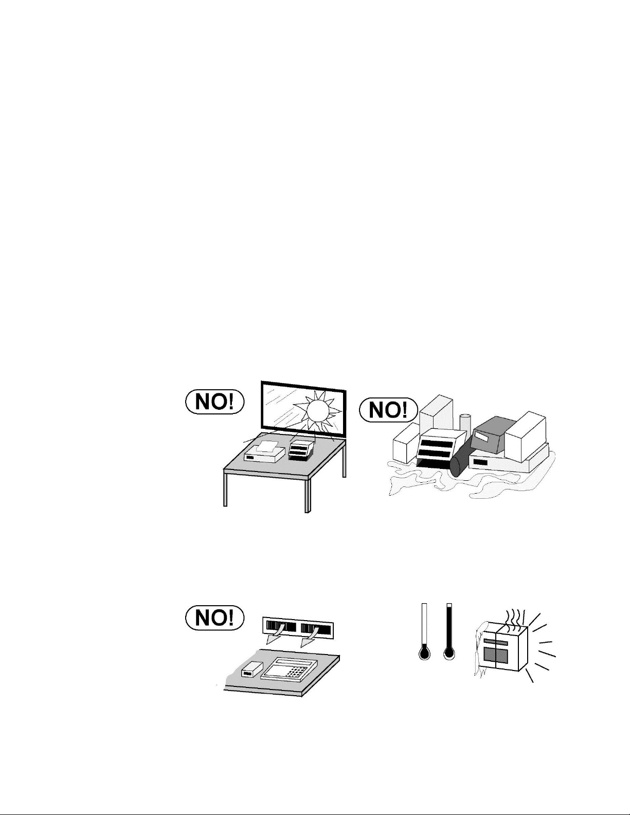
3.1.1 Environmental
The 190 indicator meets or exceeds all certification requirements within a
temperature range of 14 to 104 °F (-10 to +40 °C).
In order to keep cooling requirements to a minimum, the indicator should
be placed out of direct sunlight and to provide adequate air circulation,
keep the area around the indicator clear.
Model 190 Installation, Technical and Operation
Make certain the indicator is not directly in front of a heating or cooling
vent. Such a location will subject the indicator to sudden temperature
changes, which may result in unstable weight readings.
8400-M022-O1 Rev J
Model 190 Installation, Technical and Operation
Page 8
Insure that the indicator has good, clean AC power and is properly
grounded. In areas subject to lightning strikes, additional protection
to minimize lightning damage, such as surge suppressors, should
be installed.
3.1.2 Electrical Power
The 190 has been designed to operate from 100 to 240 VAC @
0.4A Max. at 50/60 Hz. Note that a special order is not required for
operation at 230/240 VAC.
WARNING! - To avoid electrical hazard and
possible damage to the indicator, DO NOT, under
any circumstance, cut, remove, alter, or in any
way bypass the power cord grounding prong.
The socket-outlet supplying power to the indicator should be on
a separate circuit from the distribution panel and dedicated to
the exclusive use of the indicator.
The socket-outlet shall be installed near the equipment and
shall be easily accessible. Note that the power cord on the 190
serves as the power disconnect.
The wiring should conform to national and local electrical codes
and ordinances and should be approved by the local inspector
to assure compliance.
For outdoor operations, the socket-outlet must provide GFCI
(ground fault circuit interrupter) protection.
On installations requiring 230/240 VAC power, it is the
responsibility of the customer to have a qualified electrician
install the proper power cord plug that conforms to national
electrical codes and local codes and ordinances.
8400-M022-O1 Rev J

Model 190 Installation, Technical and Operation
Page 9
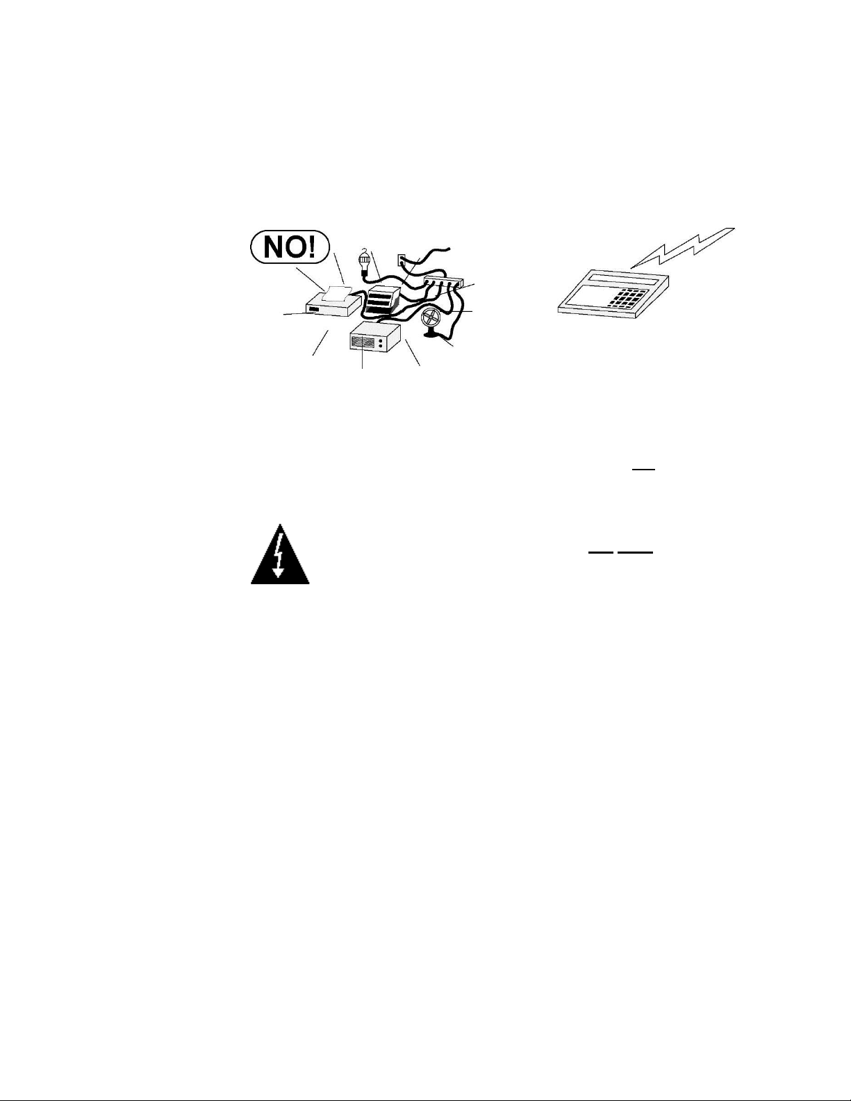
3.1.3 Electrical Noise Interference
To prevent electrical noise interference, make certain all other wall outlets
for use with air conditioning and heating equipment, lighting or other
equipment with heavily inductive loads, such as welders, motors and
solenoids are on circuits separate from the indicator. Many of these
disturbances originate within the building itself and can seriously affect the
operation of the instrument. These sources of disturbances must be
identified and steps must be taken to prevent possible adverse effects on
the instrument. Examples of available alternatives include isolation
transformers, power regulators, uninterruptible power supplies, or simple
line filters.
3.1.4 Transient Suppression
The following recommendations will help to reduce transients:
Always use shielded cables to connect signal wires to the weight
indicator.
Secure the cables in the cable clips provided inside the indicator.
Connect the cable shield (indicator end only) to a ground point
inside the indicator. Keep wires that extend beyond the shield as
short as possible.
Do not run load cell or signal cables from the weight indicator
alongside or parallel to wiring carrying AC power. If unavoidable,
position the load cell and signal cables a minimum of 24" away
from all AC wiring.
Always use arc suppressors across all AC power relay contacts (see
recommendations at www.panconcorp.com/PDFs/capacitors/QRLQuencharc.pdf).
Use zero voltage switching relays, optically isolated if possible.
8400-M022-O1 Rev J
Model 190 Installation, Technical and Operation
Page 10
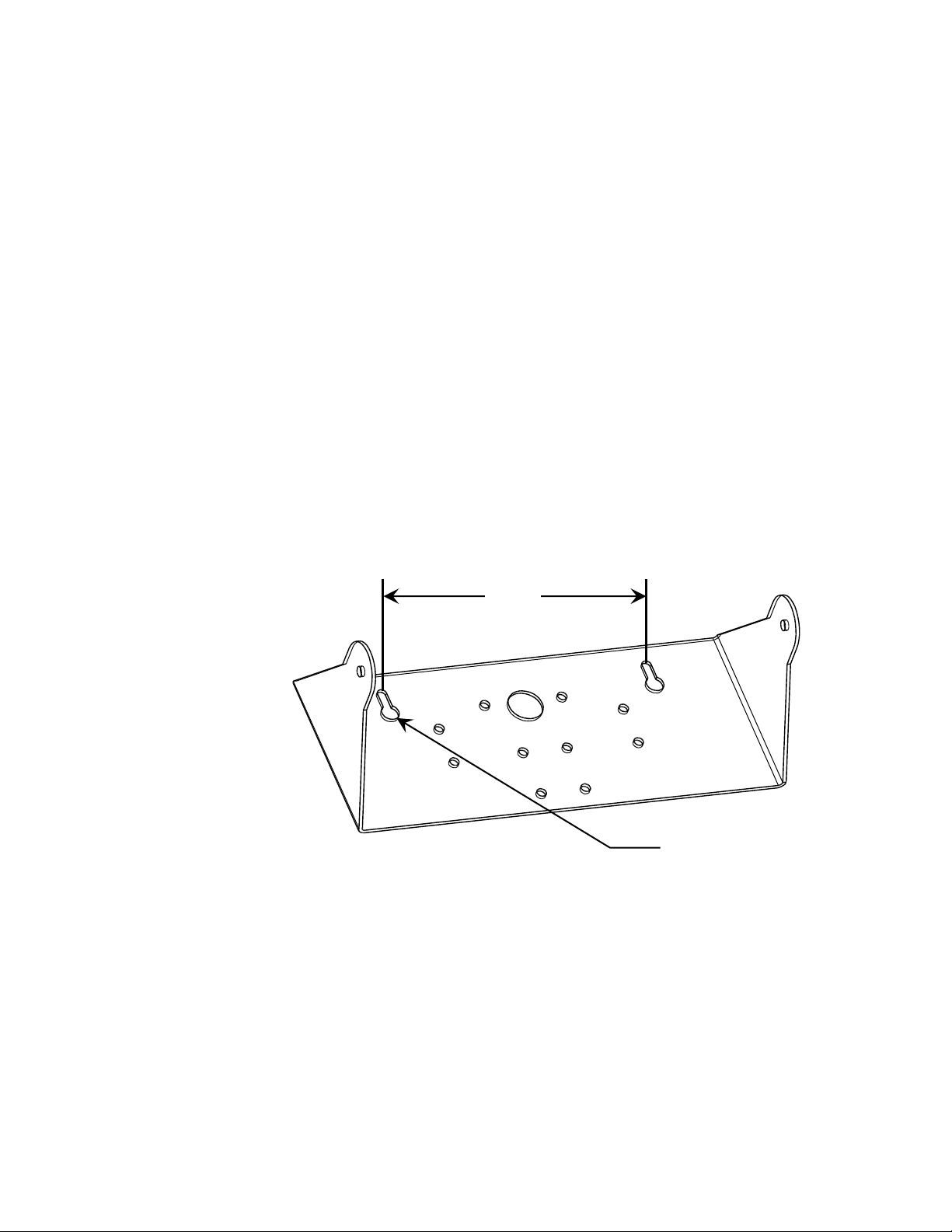
6.00"
Clearance for
#10 size screw
3.2 Mounting
Before beginning installation of your Model 190 Indicator, make
certain that it has been received in good condition. Carefully
remove it from the shipping carton and inspect it for any evidence
of damage (such as exterior dents or scratches) that may have
taken place during shipment. Keep the carton and packing material
for return shipment if it should become necessary. It is the
responsibility of the purchaser to file all claims for any damages or
loss incurred during transit.
NOTE: Should your Model 190 indicator come already installed on
a scale, the following information describing the installation of the
indicator does not apply.
The Model 190 indicator is housed in a Thermoplastic IP69K wall or
desk-mount enclosure. The gimbal may be mounted on a desktop
or other smooth, flat, horizontal surface or may be mounted on a
wall. Refer to Figure No. 1 for a layout of wall-mounting bolts.
Figure No. 1
If wall mounted, make certain the mounting surface is strong
enough to support the indicator. The mounting location should be
where the display is easily viewed while being close enough to
provide the operator easy access to the keypad. Carefully lay out
the mounting hole locations, then drill and install the anchor bolts.
Attach the gimbal to the wall and securely tighten the retaining
bolts.
8400-M022-O1 Rev J
Model 190 Installation, Technical and Operation
Page 11
CAUTION! Disconnect any external load cell
power supply before connecting load cells to the
indicator. Failure to do so will result in permanent
damage to the indicator.
AC Power
100-240 VAC
0.4 Amp
Scale
I/O
(Serial, Isolated
Inputs/Outputs)
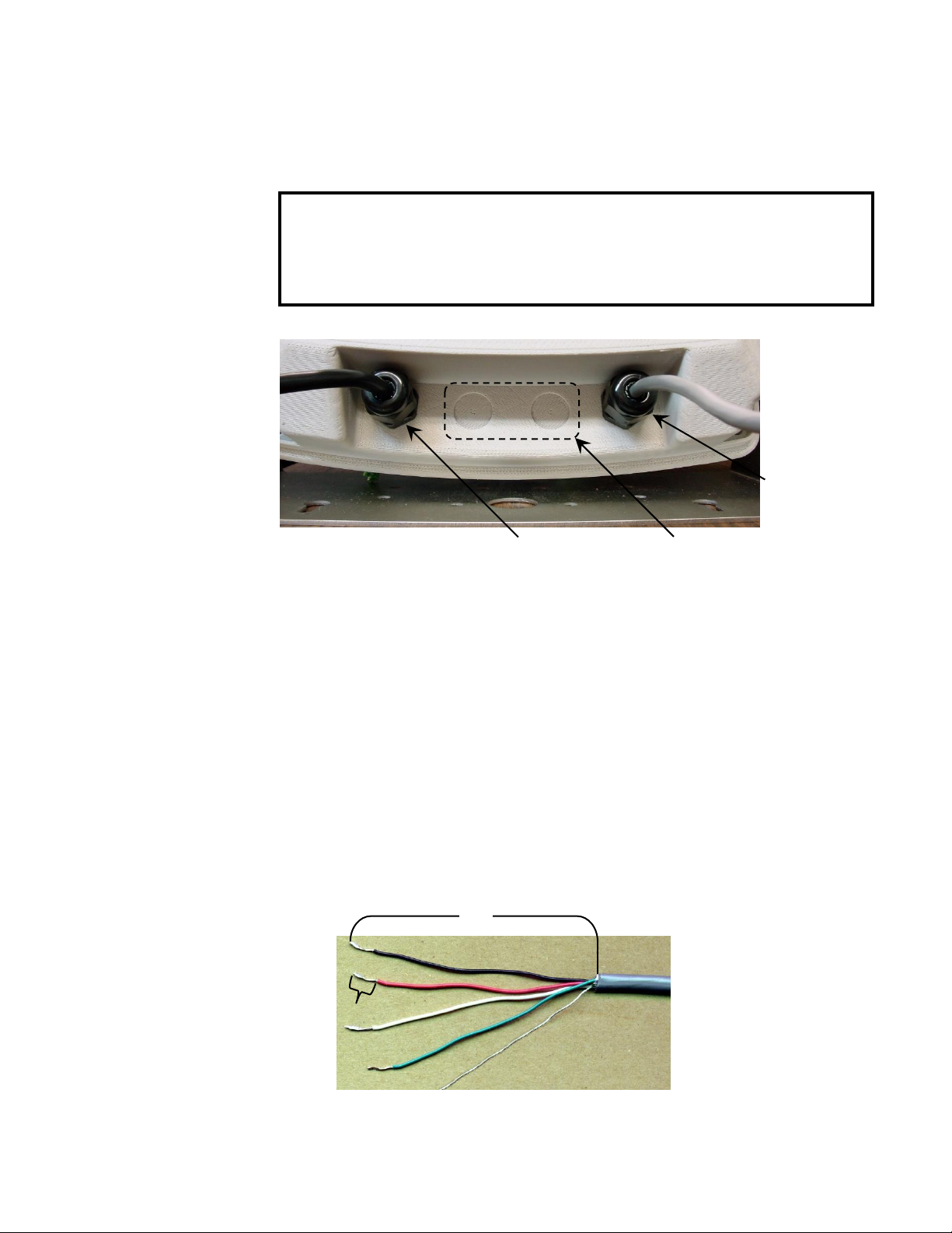
Figure No. 3
1/4”
3”
3.3 Load Cell Connections
Figure No. 2
3.3.1. Loosen the 4 Captive screws securing the rear housing to the front
housing assembly.
3.3.2. Referring to Figure No. 2, choose a gland connector for the load cell
cable and loosen it.
3.3.3. Slip the single cable from the load cell or load cell junction box
through the gland connector and into the enclosure.
3.3.4. Referring to Figure No. 3, remove 3 inches of the outer insulation
jacket.
3.3.5. Next, remove 1/4 inch of insulation from each of the six wires and
shield (with sense leads) or four wires and shield (without sense
leads).
8400-M022-O1 Rev J
Model 190 Installation, Technical and Operation
Page 12
P5 Load Cell Wiring Table
P5 Board Label
Function
P5 Board Label
Function
+EXC
+ EXCITATION
-SIG
- SIGNAL
+SEN
+ SENSE
-SEN
- SENSE
+SIG
+ SIGNAL
-EXC
- EXCITATION
SHLD
SHIELD (Connect the load cell cable shield wire here).
Insert wire
and tighten
screw.
Load Cell
Shield Wire
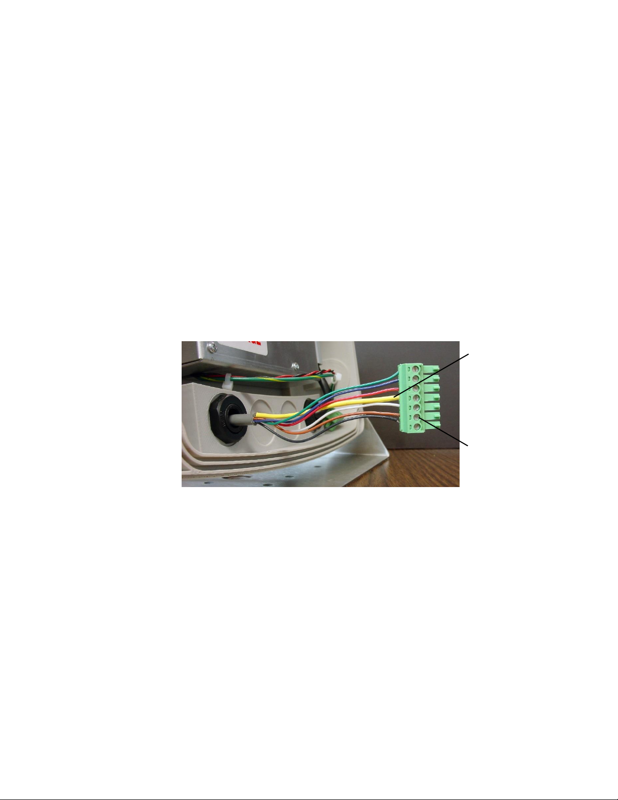
3.3.6. Remove the 7-connector terminal block connector from P5
on the 190 mainboard. Grasp the terminal block connector
and lift straight up away from the board.
3.3.7. Referring to the table below and the labels on the circuit
board for terminal connections, connect each wire to the
terminal block.
3.3.8. To terminate a wire, loosen the screws in the terminal block
and then insert the wire into the terminal opening. Tighten
the screw to secure the wire in place. See Figure No. 4.
Figure No. 4
3.3.9. Repeat the procedure until all wires are in place.
3.3.10. After all terminations have been made, remove the excess
cable from the enclosure.
8400-M022-O1 Rev J
Model 190 Installation, Technical and Operation
Page 13
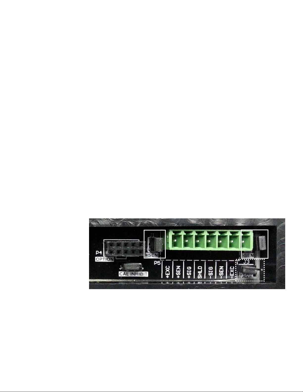
J2
J1
3.4 Load Cell Connections with Over 30 Feet of Cable
For installations with over 30 feet of cable between the indicator and the
load cells, sense wires should be used. The sense wires must be
connected between the +SENS, -SENS terminals on the indicator and the
+EXCITATION, -EXCITATION wires of the load cells or the +SENS, SENS terminals of the load cell trim board or the section seal trim board.
3.5 Sense and Deal Load Jumpers
J1 (+SEN) and J2 (-SEN) – Sense Jumpers
If the sense leads are NOT used, you must install the +SEN and -SEN
jumpers at J1 and J2 (near the P5 terminal block). These jumpers
connect the sense leads to the excitation leads. If sense leads ARE used
(as in motor truck scales or installations with over 30 feet between the
indicator and load cells), these jumpers should be open (on one pin only)
or removed.
J3 (DEAD LOAD) – Dead Load Boost Jumper
For scales with very low dead loads (less than 10% of the combined load
cell capacity), connect the DEAD LOAD (dead load boost) jumper J3 (near
the P5 terminal block).
Figure No. 5
8400-M022-O1 Rev J
Model 190 Installation, Technical and Operation
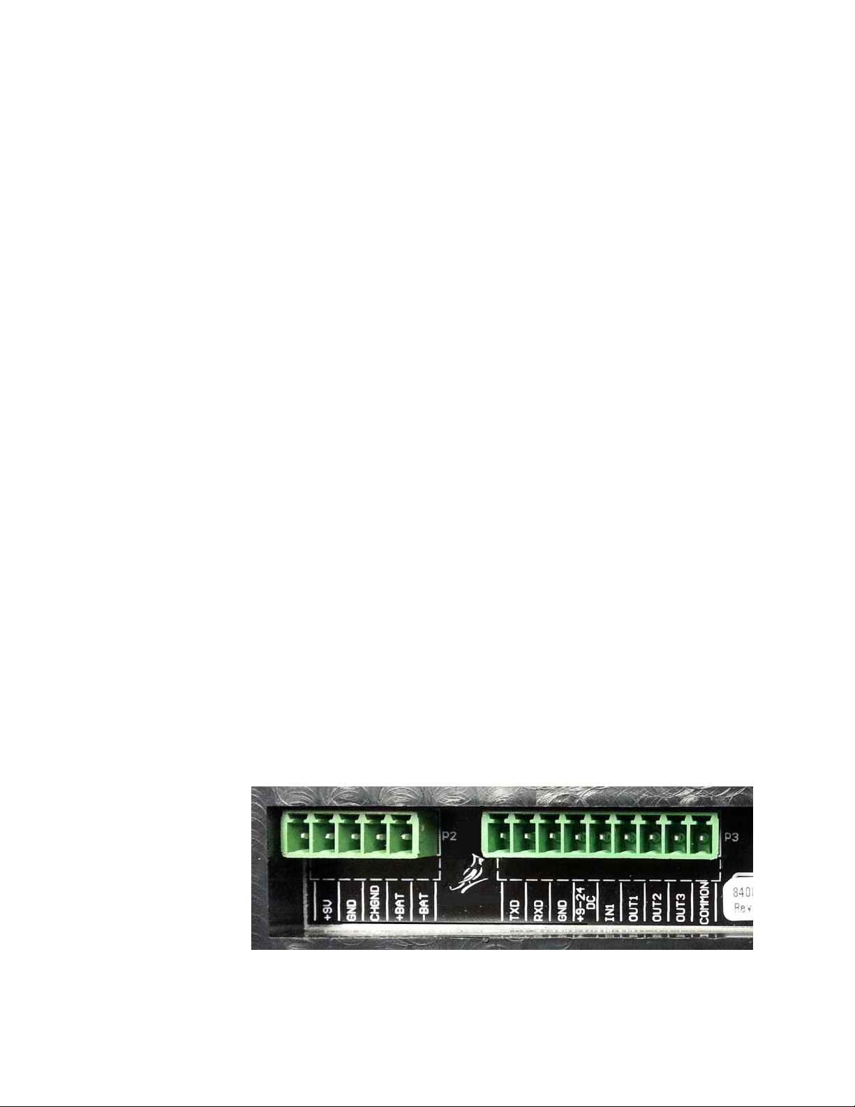
Page 14
SERIAL INTERFACE
INPUT/OUTPUTS
P3 Board Label
Function
P3 Board Label
Function
TXD
Transmit
IN1
Input 1
RXD
Receive
OUT1
Output 1
GND
Ground
OUT2
Output 2
+9-24 DC
9VDC to 24VDC
OUT3
Output 3
COMMON
Common
P3
3.6 Serial and I/O Cable Installation
3.6.1. Loosen the 4 Captive screws securing the rear housing to
the front housing assembly and then loosen a gland
connector for the serial cable. Refer to Figure No. 2 for an
illustration of the connector layout.
3.6.2. Slip the serial cable through the gland connector and into
the enclosure.
3.6.3. Remove 3" of the outer insulation jacket then remove 1/4"
of insulation from each of the wires (refer to Figure No. 3).
3.6.4. Remove the 9-connector terminal block connector from P3
on the 190 mainboard. Grasp the terminal block
connector and lift straight up away from the board.
3.6.5. Referring to the table below and the labels on the circuit
board for terminal connections, connect each wire to the
terminal block.
3.6.6. To terminate a wire, loosen the screws in the terminal
block and then insert the wire into the terminal opening.
Tighten the screw to secure the wire in place.
3.6.7. Repeat the procedure until all wires are in place.
3.6.8. After all terminations have been made, remove the excess
cable from the enclosure.
Figure No. 6
8400-M022-O1 Rev J

Model 190 Installation, Technical and Operation
Page 15
P2 Board Label
Function
+9V
VDC
GND
Ground
CHGND
Chassis Ground
+BAT
+ (Plus) Battery
-BAT
- (Minus) Battery
P2
Figure No. 7
3.7 P3 I/O Interconnections
3.8 P2 Power Connections
Figure No. 8
8400-M022-O1 Rev J

Model 190 Installation, Technical and Operation
Page 16
3.9 Re-Installing the Front Panel
3.9.1. After all terminations have been made, remove the excess
cable from the indicator enclosure and securely tighten
each of the cable gland connectors.
3.9.2. Use a wrench to insure the gland connectors are tight (to
maintain a water-tight seal) but do not over-tighten them.
3.9.3. Make certain no cables or wires are exposed between the
rear housing and front housing assembly and then place
the front housing assembly onto the rear housing.
3.9.4. Secure by tightening the 4 Captive screws loosened
earlier.
8400-M022-O1 Rev J
Page 17
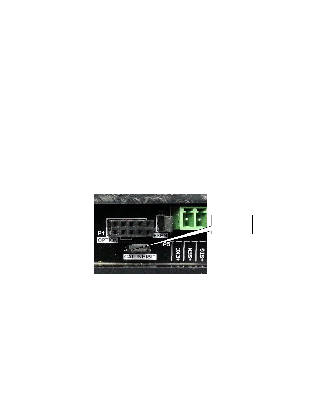
CAL Inhibit
Jumper J4
J4
4. INDICATOR SETUP
4.1 Calibration Inhibit Jumper
Your Model 190 indicator has been thoroughly tested and calibrated
before being shipped to you. If you received the indicator attached to a
scale, calibration is not necessary. If the indicator is being connected to
a scale for the first time or recalibration is necessary for other reasons,
proceed as indicated.
Calibration and Setup of the indicator is accomplished entirely by the
keypad. However, it may require changing the position of the calibration
inhibit jumper depending on the method of sealing required by your local
metrology laws.
The calibration inhibit jumper (J4) is located on the main printed
circuit board and can only be accessed by removing the front panel
of the indicator.
Model 190 Installation, Technical and Operation
Figure No. 9
8400-M022-O1 Rev J

Model 190 Installation, Technical and Operation
Page 18
USA
Domestic or International
LFt
Legal For Trade
Unit1
Weighing Units 1 (Primary Units)
Int
Interval Setting
dPP
Decimal Point Precision
CAP
Capacity
Unit2
Weighing Units 2 (Secondary Units)
trA
Zero Tracking Range
trL
4% Zero Limit
PU0
Power Up Zero
dFLt
Digital Filter Number
F
Filter Level Amount
B
Filter Break Range
Sr
Sample Rate
UnS
Motion Range
SC
Stable Count
IMPORTANT! The following setup parameters CAN NOT
be changed with the calibration inhibit jumper (J4)
installed:
8400-M022-O1 Rev J
Model 190 Installation, Technical and Operation
Page 19
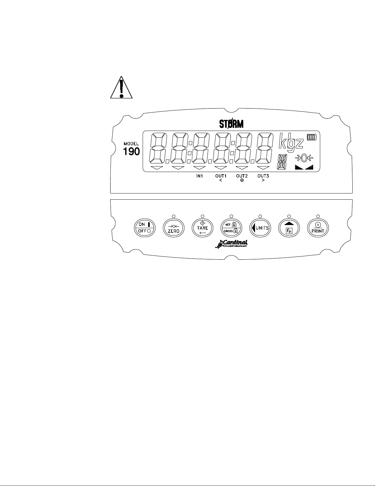
4.2 Calibration Data Entry
The Model 190 uses a capacitive touch keypad that requires a
“finger touch” to function. The keypad will not operate with
other items such as pen, pencil or tools.
Figure No. 10
During the indicator setup and calibration process it will be necessary to
enter operational parameters via the 190 keypad.
Pressing the TARE key will cause the data entered or displayed
to be retained and the 190 to advance to the next prompt.
The functions of numeric keys are replaced by using the UNITS/
and the Fn/ keys.
The cursor location is identified by the blinking character and can
be advanced to the left to the next position by pressing the
UNITS/ key.
Pressing the Fn/ key will change the blinking character to the next
value or setting. Continue to press this key to "toggle" between the
different available values or settings for the setup parameter.
Pressing the Fn/ key when a setup parameter (not a parameter
value or setting) is displayed, will "backup" to the previous
parameter prompt.
8400-M022-O1 Rev J

Model 190 Installation, Technical and Operation
Page 20
8400-M022-O1 Rev J
 Loading...