

Page 1

Technical Support: Ph: 866-254-8261 v techsupport@cardet.com
Waist-High
Dial Physician Scale
Models 090 and 090KG
Operating Instructions
CARDINAL SCALE MFG. CO.
0044-M323-O1 Rev B
PO Box 151 v Webb Cit
y
, MO 64870
07/06
Ph: 417-673-4631 v Fax: 417-673-5001
Printed in USA
www.detectoscale.com
Page 2

Page 3
SPECIFICATIONS
Capacity
Model 090
300 lb x 1 lb
Model 090KG
150 kg x .5 kg
UNPACKING INSTRUCTIONS
v
Remove scale from the carton by lifting up with equal
force on the column and platform base of the scale.
v
Check for any damage incurred in shipping. If the
scale has been damaged, place a claim with the
carrier. If the scale must be returned, use the original
carton and packing material.
v
Remove all plastic wrapping, banding and packing
material from the scale, as well as the cardboard
between the levers, and foam block inside the scale
base. The scale will not function properly if any of the
plastic wrap, the banding on the base, the cardboard
between the levers or foam block is still in place.
v
Set the scale on a flat, level floor or low cut carpet.
OPERATING INSTRUCTION
Zeroing the Scale
v
Rotate the zero adjust knob at the back edge of the dial
head to adjust the pointer until the “0” reading is obtained.
Weighing Procedure
v
Step onto the scale, position both feet firmly on the
platform. The pointer will indicate the current weight.
v
Step off the scale and re-zero the scale if necessary.
CARE AND CLEANING
v
DO NOT spray; water directly on the scale. The scale may be cleaned using a damp, soft
cloth and mild detergeant. NOTE! Some types of paper towels may scratch the dial lens.
v
DO NOT use acetone, alcohol, or other volatile solvents for cleaning.
v
DO NOT oil any parts of the scale.
Date of Purchase ________________
Purchased From _________________
_______________________________
_______________________________
Retain this information for future use.
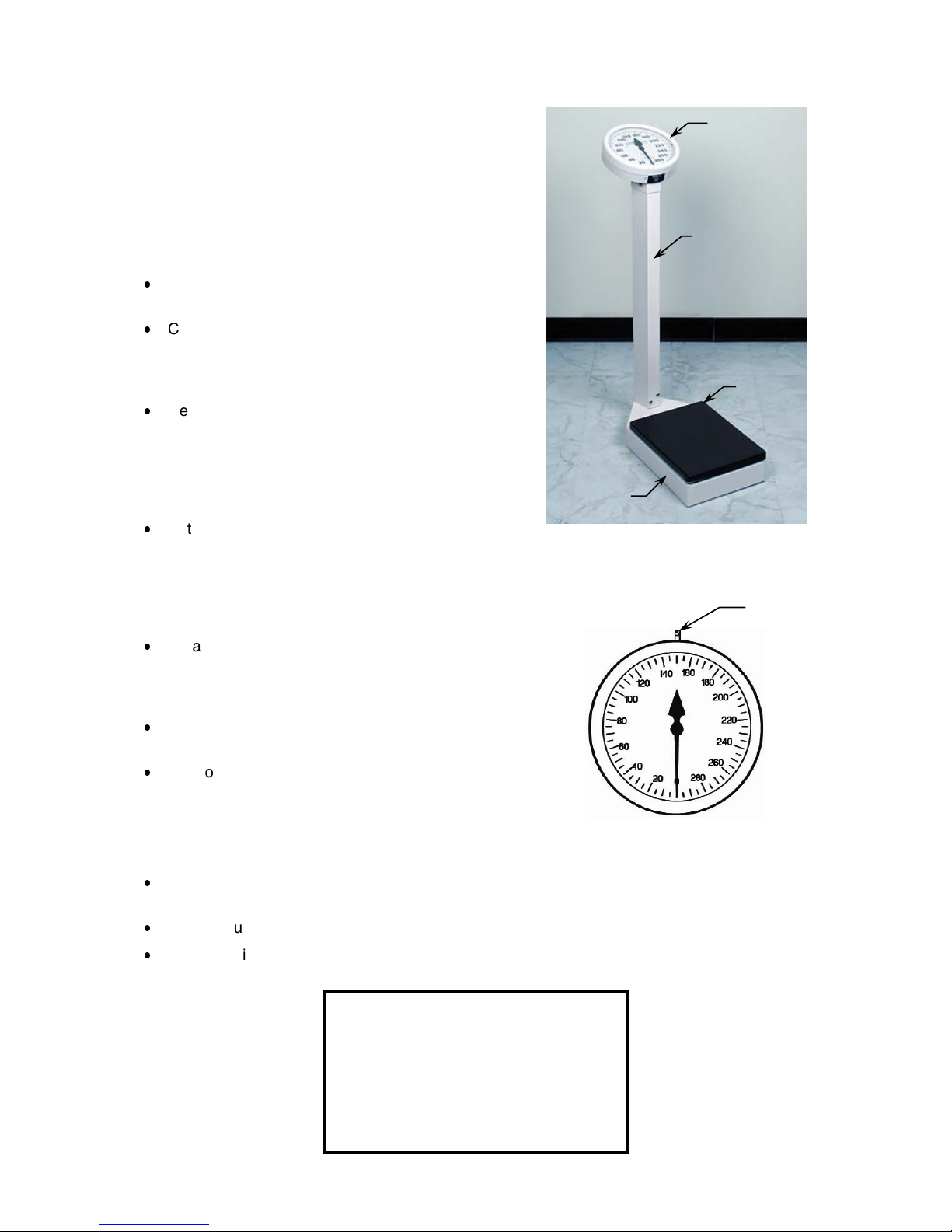
Column
Dial Head
Platform
Platform
Base
Zero
Adjust
Knob
DIAL HEAD
1
Page 4

OPTIONAL WHEELS
How to setup the Detecto Waist-High
Dial Physican Scale with roller wheels.
1. Remove the two lower screws in
the back of the column.
2. Place the wheel bracket against
the back of the column and align
the holes in the bracket with the
holes in the column.
3. Install the two screws removed
in step 1, securing the wheel
bracket to the column.
OPTIONAL HEIGHT ROD
Optional Height Rod Installation
1. Remove the height rod from the box.
2. If not already installed, insert the two hex head screws from the hardware pack into the
holes in the front of the column and tighten them with the included wrench until the hex
heads are 1/8" from the column.
3. Place both height rod brackets over the two pre-installed hex head screws and pull down.
4. Use the included wrench to tighten both hex head screws. Do not overtighten the screws.
Height Rod Operating Guide
1. Before the person steps onto the scale platform, the spoon should be rotated to the
horizontal position, and raised well above the person’s apparent height.
2. The person may now step onto the scale platform. The spoon should be held horizontal
and above the person’s head.
3. Carefully lower the spoon, while keeping it horizontal, until it rests gently upon the top of
the person’s head. If the person is shorter than 3' 4" (101.5 cm), push the latch to the right,
while simultaneously pushing down on the spoon, until the spoon rests horizontally upon
the top of the person’s head.
4. Read the height of the person as follows:
If the back of the spoon points to the outer height rod, then it points to the correct height.
If the back of the spoon points to the inner height rod, then the correct height is read at
the top of the outer height rod (see “Read” arrow on the outer height rod).
5. While holding the spoon horizontally, raise the spoon above the person’s head. The
person may now step off of the scale platform. Hold the spoon horizontal until the person
is clear of the height rod.
6. Rotate the spoon back to the vertical position and adjust the height rod back to the rest
position (i.e. the spoon should be locked in place within the inner height rod and the inner
rod should be at its lowest position).
Screws and
wheels bracket
2
Page 5
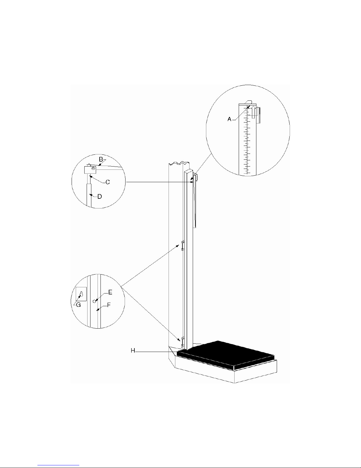
OPTIONAL HEIGHT ROD, Cont.
A = “Read” line
B = Spoon
C = Inner height rod
D = Outer height rod
E = Hex head screw
F = Column
G = Mounting bracket
H = Height rod sits on top of the scale base
3
Page 6

PARTS IDENTIFICATION
ITEM QTY PART NUMBER DESCRIPTION
1 1 3P1001X Base Weldment
2 1 430XG3R800 Column Weldment
3 1 3P2011X Platform Weldment
4 1 3P8068 Platform Cover
5 1 *0033-D203-0A Height Rod Assembly
6 4 6021-1629 Sheet Metal Screw #10 X 1/2”
7 2 6021-1058 THM Scw, #10-32 x .375
8 1 0044-C304-0A Pinion Assembly
9 1 3P8002X Long Lever Assembly
10 1 3P8003X Short Lever Assembly
11 1 0044-B294-08 Steelyard Rod
12 2 3P60 Check Plate
13 1 0044-C292-08 Column Top Adapter
14 8 6021-1423 THMS 1/4”-20 x 0.50
15 2 6013-0045 Hex Nut 1/4”-20
16 6 6021-2058 FHM Scw, Wht Nylon #6-32 x .5
17 6 6021-2043 RHM Scw, #6-32 x .25
18 2 0044-B172-08 Standoff
19 1 3P122 Bumper
20 2 6021-0985 Hex Washer Head Scw #10 X 1/2”
21 4 3P8059 Hanger
22 1 2U58 Center Loop
23 4 3P2087 Platform Load Bearing
24 1 0044-C305-0A Zero Adjust Assembly
25 6 6024-0047 Lock Washer 1/4”
26 4 63K1038 Base Leg
27 1 0044-C204-08 Bezel Ring
28 1 0044-B194-08 Friction Cap
29 4 6021-0622 RHM Scw, #8-32 x .25 Phil Drive
30 A/R 6560-0021 Locite #222-31
31 1 0044-C125-208 Lens
32 2 6024-1000 Internal Star Washer #8
33 1 0044-B223-08 Sash Mounting Plate
34 1 0044-C295-08 Base Plate
35 2 0044-D129-08 Sash Ring Half
36 1 0044-C321-08 Dial Chart for 090
37 1 0044-C322-08 Dial Chart for 090KG
38 1 0044-B141-08 Sash Ring Bracket
39 1 0044-C312-0A Driveline Assembly
40 1 0044-B151-08 Decal, Sash Button
41 1 6021-1836 PHM Scw, #8-32 x 3/16” Phil Drive
* Optional, Brackets Not Shown
4
Page 7

PARTS IDENTIFICATION, Cont.
5
Page 8
 Loading...