

Cardiac 20100, 20300, 20002 User manual
오적
SNOISIAZY
L
A
yl
akla
1
mr
я
TE
で
mr
で
afer
Г
ῃ
(HSVI4IWOMJI
ABZL
48131-00000
ae
art
я
or
+
E
κ.
と
я
Е
È
ος
=
}
ši
=
ero
or
Η
É
E
EG
E
EY
5
HE
E
“e
s
à
EM
-.
moa
ss
dde
35
la:
pe
cause
#8
NYHS
NEC
р
ee
=
č
SH
x
È
a
seu
DE
È
和
ceca
ne
seu
soso
Je
È
μα
s
p
se
|
zem
leee
ή
个
nce
P
τ
αν
ΤΝ
DI
sere
scena
www
|
Tarn
Os
se
ー
HE
o»
I
©
Е
시
A
이
AA
NELERE
+
oe
новые
anti
o
|
el
me
È
A
ml
es
H
"m
do
TE
fomos
[fr
my
キダ
Mo
ni
3
ADO
Se
mr
©
4
:
sc
x
м
=
09
P
a
και»
ma”,
Pi
È
Pp
dü
UR
HE
E
À
=
$
Я
È
Em
—
00009
89
mond
«а:
.
>
に
|
“arti,
5
35
e
>
σσ
A)
<a>
FI
세타
p“
b
Β
399308v2
MOS
=
14
1188
Sp
SDA
x
M8
FF
ES
TOTS
мой
Fw
i
이
Ея
Ея
fas
BEZİ
E
DE
des
foo
き
E
x
e
s
“Ek
s
E
E
的
EN
Ελ
ES
wehbe
©
Е
a"
Cam
$
È
se
E
A
RE
R
=
8
He
»
스노
우지
ει)
}
ㅠ
~
.
ο
E
a
Tempos
qadoags
JSUWINIO
SSI
ο
=
dj
ー
mndino
onto
HES
3-6
seipieo
ep
/
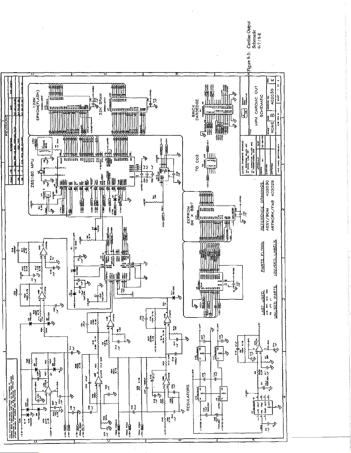
2-6
:£-6
MB
회
no
Te
Duvm3Hos
OVIAYVD
ΡΕ
WAI
-=
lee-*o-co
τινα
~
の
о
ES
оно
Rs
Same
so
como
no!
И
de
м
.
=
N
=
NROTI
SISVI
IS
ГУТ
a
spon
FT
т
ww
mak
y
Ti
ocozor
cu
L I
E
ems]
amoo]
0$020%
GZOZOd
9V3/MNOMLUV
WOS/ASSY
I
SANTI
$1599
Eso
LO
E
DIS
ia
sin
い
I
>
změ
mem
á
기
a

Cardiac
Output
Board
MIDE
352100-0102A
352100-0103A
352100-0104A
352100-0150А.
352100-0474А.
352400-0106А.
354000-0106А.
1354000-0317A
356000-0026А,
364000-0109А.
364000-0110A
364000-0208A
1364000-0237A
364000-0246A
364000-0273A
364000-0274A
|364000-0278A
364000-0288A
|364000-0289A
364000-0290A
364000-0292A
364000-0293A
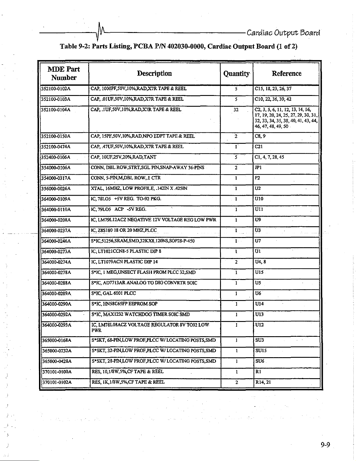
Table
Part
9-2:
Parts
Listing,
CAP,
1000PF,50V,10%,RAD,X7R
CAP,
.01UF,50V,10%,RAD,X7R
CAP,
.1UF,50V,10%,RAD,X7R
CAP,
15PF,50V,10%,RAD,NPO
CAP,
47UF,50V,10%,RAD,X7R
CAP,
10UF,25V,20%,RAD,
CONN,
DBL
CONN,
5-PIN,M,DBL
XTAL,
16MHZ,
1С,
78105
+5У
1C,79LO5
IC,
IC,
S*IC,51256,SRAM,SMD,32KX8,120NS,SOP28-P-450
IC;
IC,
S*IC, | MEG,UNSECT
S*IC,
S*IC,
S*IC,
S*IC,
IC,
ACP
LM79L12ACZ
Z8S180
18
LT1021CCN8-5
LT1079ACN
AD7713AR
GAL
6001
HN58C65FP
MAX1232
EMT8LOSACZ
PCBA
Description
ROW,STRT,SGL
ROW,.E
LOW
PROFILE,
ВЕС.
ТО-92
-5V
REG.
NEGATIVE
OR
20
MHZ,PLCC
PLASTIC
PLASTIC
FLASH
ANALOG
PLCC
EEPROM
WATCHDOG
VOLTAGE
TANT
РКС.
DIP
DIP
TO
SOP
P/N
402030-0000,
TAPE & REEL
TAPE © REEL
TAPE & REEL
EDPT
TAPE & REEL
TAPE & REEL
PIN,SNAP-AWAY
CTR
.142IN X .425IN
`
12V
VOLTAGE
8
14
PROM
PLCC
DIG
CONVRTR
TIMER
SOIC
REGULATOR
36-PINS
REG
32,SMD
SOIC
SMD
8V
TO92
LOW
LOW.
Cardiac
Quantity
PWR
Output
5
5
32
2
г
5
2
1
1
1
1
1
1
1
1
2
1
1
1
1
1
1
Board
C15,
18,
cio,
22,
C2,
3,
5, 6,
17,
19,
32, 33,
46,
47,
C8,
9
cal
Cl,
4,
7,
JP1
P2
U2
010
Ul
U9
U3
UT
Ul
U4,
8
U15
US
U6
1014
U13
912
(1
of
2)
Reference
23,
26,
37
36,
39,
42
11,
12,
24,
45
25,
38,
50
13,
27,
40,
20,
34, 35,
48, 49,
28,
14,
29,
30,
41,
43,
16,
31,
44,
365000-0168А
363000-0232A
363000-0428A
370101-0100A
370101-0102Α.
S*SKT,
68-PIN,LOW
S*SKT,
32-PIN,LOW
S*SKT,
28-PIN,LOW
RES,
10,1/8W,5%,CF
RES,
1K,1/8W,5%,CF
PROF,PLCC
PROF,PLCC
PROF,PLCC
TAPE & REEL
TAPE & REEL
W/
W/
W/
LOCATING
LOCATING
LOCATING
POSTS,SMD
POSTS,SMD
POSTS,SMD
1
1
1
1
2
SU3
SUIS
SU6
.
RI
R14,
21
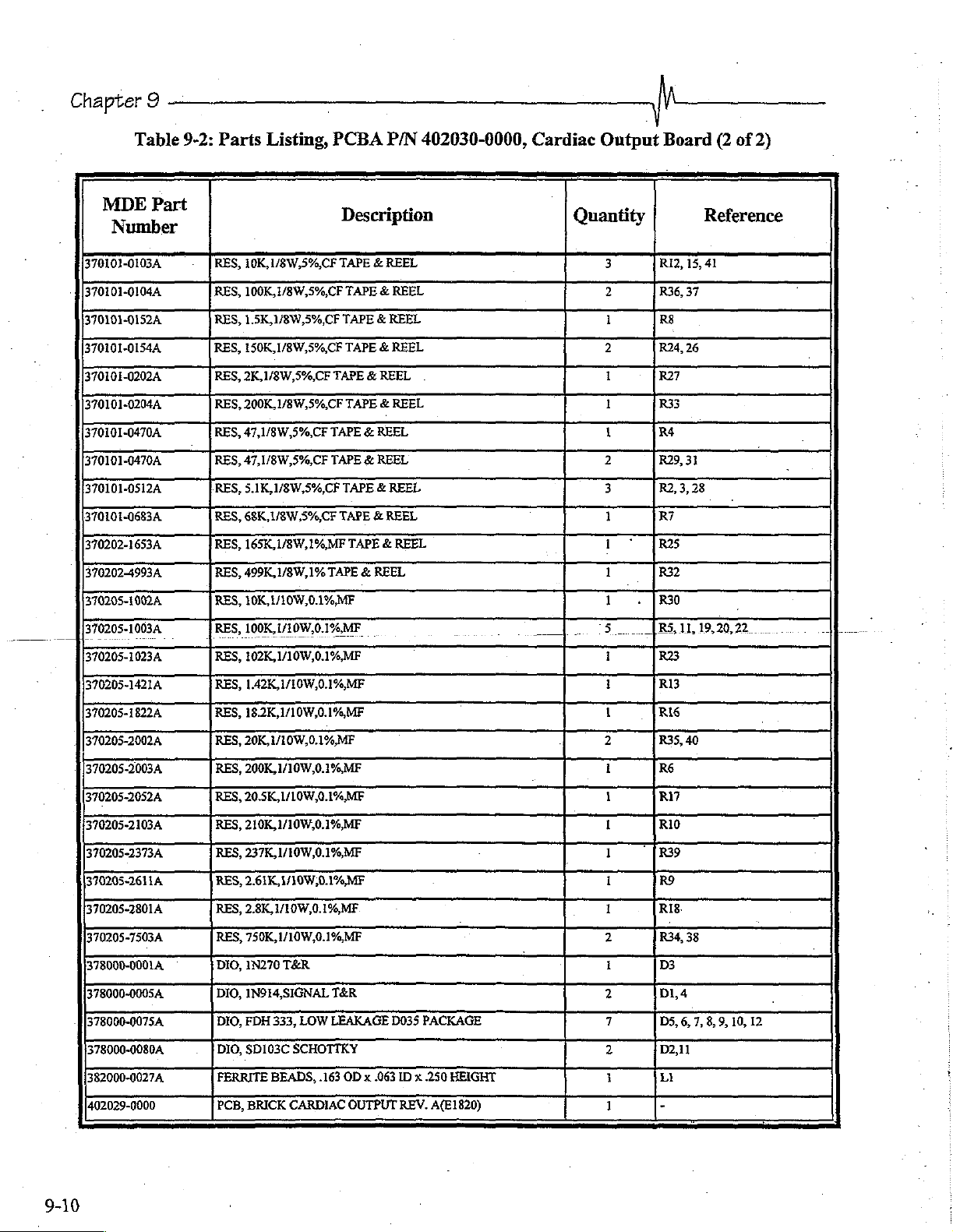
Chapter
9
Table
MDE
370101-0103A
370101-0104A
370101-0152A
370101-0154A
370101-0202A
370101-0204A
370101-0470A
370101-0470А
370101-0512A
370101-0683A
[370202-1653A
370202-4993A
370205-1002A
370205-1003A
370205-1023A
320205-1421A
37020518224
370205-2002A
370205-2003A
370205-2032A
370205-2103A
370205-2373A
390205-2611A
370205-2801A
370205-7503A
378000-0001À
378000-0005A
378000-0075A
378000-0080A
382000-0027A
402029-0000
bart
9-2:
Parts
RES,
RES,
RES,
RES,
RES,
RES,
RES,
RES,
RES,
RES,
RES,
RES,
RES,
RES,
RES,
RES,
RES,
RES,
RES,
RES,
RES,
RES,
RES,
RES,
RES,
DIO,
DIO,
DIO,
DIO,
FERRITE
PCB,
Listing,
10K,1/8W,5%,CF
100K,1/8W,5%,CF
1.5K,1/8W,5%,CF
150K,1/8W,5%,CF
2K,
1/8W,5%,CF
200K,1/8W,5%,CF
47,1/8W,5%,CF
47,1/8W,5%,CF
5.1K,1/8W,5%,CF
68K,
1/8W,5%,CF
165K,1/8W,1%,MF
499K,1/8W,1%
10K,1/10W,0.1%,MF
100K,1/10W,0.1%,MF.
102K,1/10W,0.1%,MF
1.42K,1/10W,0.1%,MF
18.2K,1/10W,0.1%,MF
20K,1/10W,0.1%,MF
200K,
1/10W,0.1%MF
20.5K,1/10W,0.1%ME
210K,1/10W,0.1%,MF
237K,
1/10W,0.1%,MF
2.61K,1/10W,0.1%,
2.8K,1/10W,0.1%,MF
750K,
1/10W,0.1%MF
1N270
TER
IN914,SIĞNAL
FDH
333,
SD103C
BEADS,
BRICK
PCBA
Description
TAPE & REEL
TAPE & REEL
TAPE & REEL
TAPE
TAPE & REEL
TAPE & REEL
TAPE & REEL
TAPE & REEL
TAPE & REEL
TAPE & REEL
TAPE & REEL
TAPE & REEL
MF
TER
LOW LEAKAGE
SCHOTTKY
.163
OD x 063
CARDIAC
OUTPUT
de
P/N
402030-0000,
REEL
D035
PACKAGE
ID x 250
REV.
HEİGHT
A(E1820)
Cardiac
ーー
Output
Quantity
3
2
1
2
1
1
1
2
3
1
1
1
1
5
1
1
1
2
I
1
I
1
1
1
2
1
2
7
2
1
Board
Riz,
R36,
R$
R24,26
R27
R33
R4
R29,
R2,
R7
R25
R32
R30
(RS,11,19,20,22.
R23
RI3
RI6
R35,
R6
R17
RIO
R39
R9
RIB.
RE
D3
DL4
DS,
D2,11
LI
(2
Reference
15,41
37
31
3,
28
40
6, 7,
8,
9,
of
|
10,
12
2)
9-10
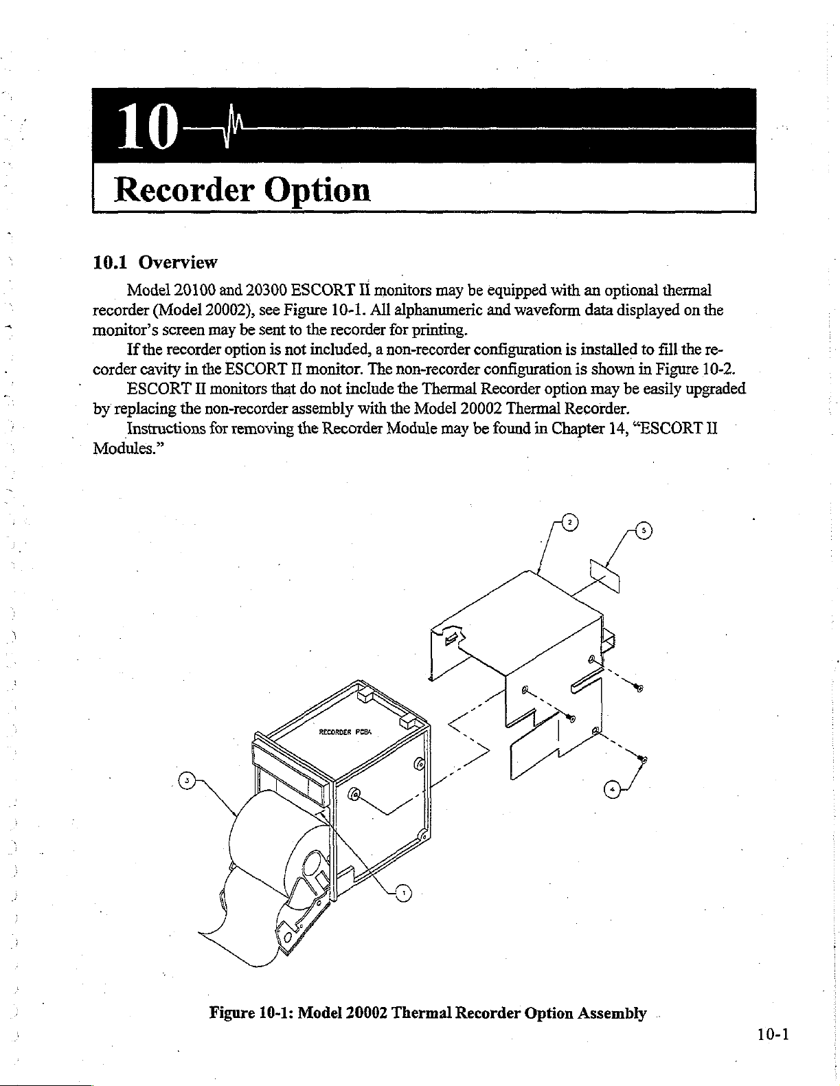
Recorder
Option
10.1
Model
recorder
monitor’s
If
corder
°
ESCORT
by
replacing
Instructions
Modules.”
Overview
20100
(Model
screen
the
recorder
cavity
in
the
Il
the
and
20300
20002),
may
be
option
ESCORT
monitors
non-recorder
for
removing
see
Figure
sent
is
not
that
to
ESCORT
II
do
assembly
the
II
monitors
10-1.
All
the
recorder
included, a non-recorder
monitor.
not
include
Recorder
The
with
Module
for
the
may
alphanumeric
printing.
non-recorder
the
Thermal
Model
20002
may
be
equipped
and
configuration
configuration
Recorder
Thermal
be
found
with
waveform
option
in
Chapter
an
optional
data
displayed
is
installed
is
shown
may
be
Recorder.
14,
“ESCORT
thermal
to
fill
the
in
Figure
easily
on
the
re-
10-2.
upgraded
II
A
JTS
Figure
A
10-1:
Model
A
20002
Thermal
Recorder
Option
Assembly
.
10-1

Chapter
10
-
|
10-2
Figure
10-2:
Model
20100/20300
Non-Recorder
Assembly
y
Recorder
Option
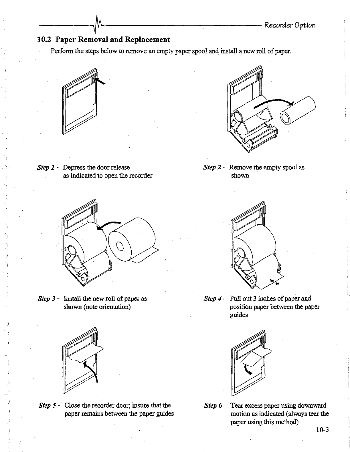
10.2
Step 1 -
Paper
Perform
Removal
the
steps
Depress
as
the
indicated
below
door
to
open
and
Replacement
to
remove
release
the
recorder
an
empty
paper
spool
and
install a new
shown
roll
of
paper.
Step 3 -
Step
5-
Install the
shown
Close
paper
new
(note
orientation)
the
recorder
remains
roll
of
paper
door;
between
as
.
insure
the
paper
that
the
guides
Step.4 - Pull
position
guides
Step 6-
Tear
motion
paper
out 3 inches
paper
between
excess
paper
as
indicated
using
this
method)
of
paper
using
(always
and
the
paper
downward
tear the
10-3
Chapter
MID
358100-01334
360600-0018A
366000-0008A
366000-0015A
378000-0036A
399100-0010А.
401682-0000
401978-0000
10
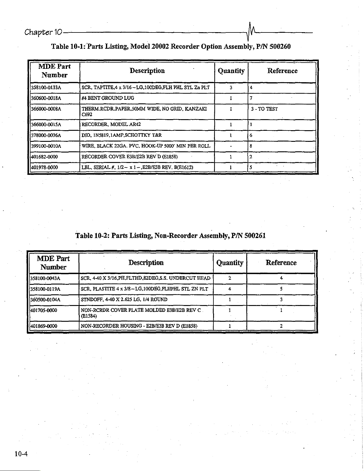
Table
Part
10-1:
Parts
SCR,
TAPTITE,4 x 3/16—LG,100DEG,FLH
#4
BENT
THERM.RCDR
RECORDER,
DIO,
1N5819,1AMP,SCHOTTKY
WIRE,
BLACK
RECORDER
LBL,
SERIAL
Listing,
GROUND
MODEL
COVER
#,
Model
Description
LUG
PAPER,
SOMM
AR42
22GA.
PVC,
E3B/E2B
1/2~ x 1~,E2B/E3B
20002
WIDE,
T&R
HOOK-UP
REV D (E1858)
Recorder
PHL
NO
GRID,
5000’
REV.
B(E1612)
STL
KANZAKI
MIN
PER
Option
Zn
PLT
ROLL
Assembly,
Quantity
3
1
1
1
1
-
1
1
1
P/N
Reference
4
7
3-
TO
TEST
1
6
8
2
5
500260
MDE
358100-0043A
358100-0119A
360500-0104A,
401705-0000
401869-0000
Part
Table
10-2:
Parts
SCR,
4-40 X 3/16,PH.ELTHD,82DEG,S.S.
SCR,
PLASTITE 4 x
STNDOFF,
NON-RCRDR
(81584)
NON-RECORDER
4-40
COVER
]
Listing,
Description
3/8~LG,100DEG,FLHPHL
X 2.625
LG,
PLATE
HOUSING - E2B/E3B
Non-Recorder
1/4
ROUND
MOLDED
Assembly,
UNDERCUT
E3B/E2B
REV D (E1858)
STL
REV
HEAD
ZN
C.
PLT
P/N
500261
Quantity
2
4
1
1
1
Reference
4
5
3
a
2
10-4
Recorder
Option
|
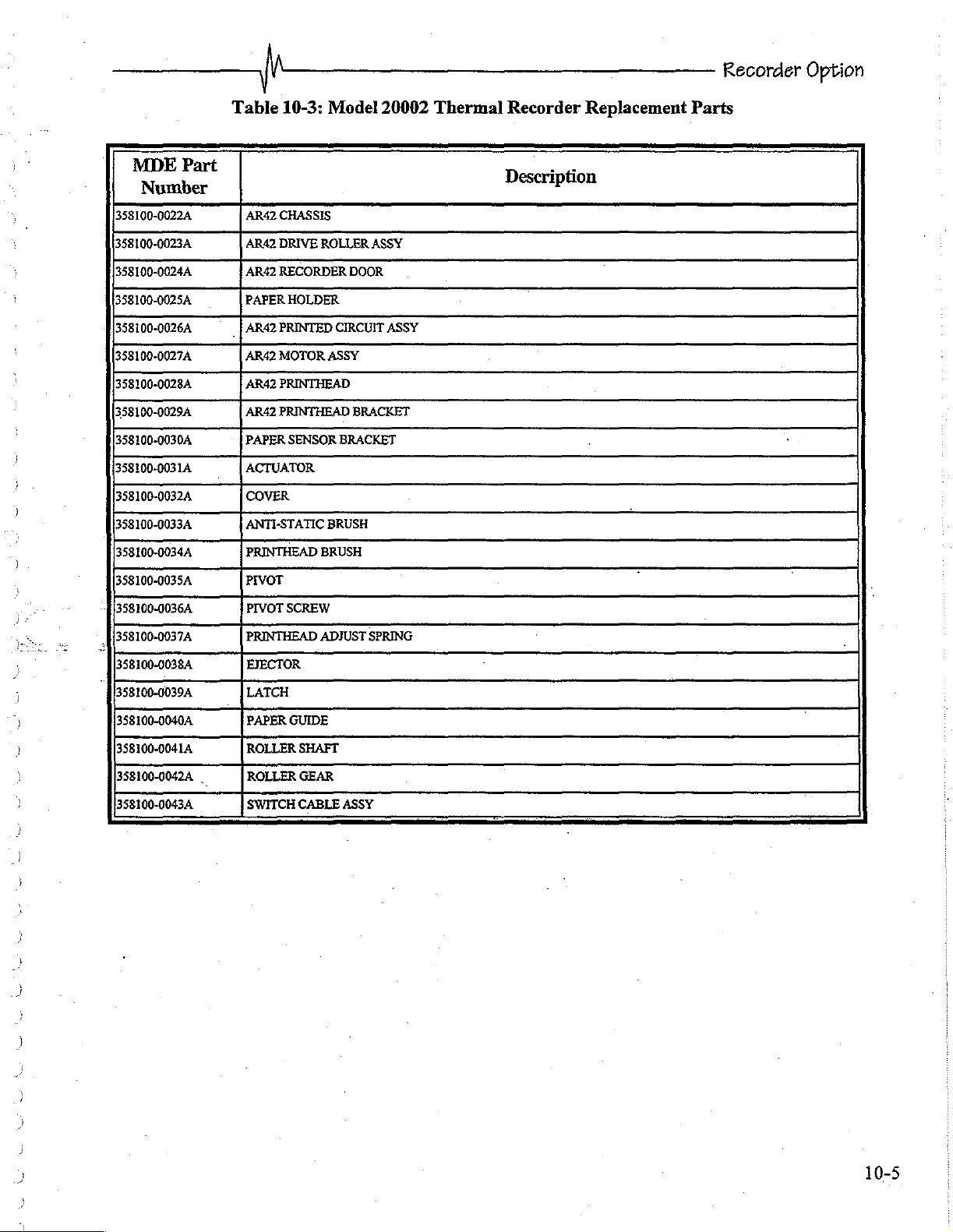
Table
10-3:
Model
20002
Thermal
Recorder
Replacement
Parts
MDE
358100-00224
358100-0023A
358100-0024A
358100-0025А
358100-0026A
358100-0027A
358100-0028A
358100-0029A
358100-0030A
358100-0031A
358100-0032A
358100-0033A
358100-0034A
358100-0035А
Å|358100-0036A
和
558100-0037A
‘[[558100-0038a
35810-00394
35810-00404
358100-0041A
358100-0042A | ROLLER
358100-0043A
Part
Number
AR42
CHASSIS
AR42
DRIVE
ROLLER
AR42
RECORDER
PAPER
HOLDER
_|
AR42
PRINTED
AR42
MOTOR
AR42
PRINTHEAD
AR42
PRINTHEAD
PAPER
SENSOR
ACTUATOR
COVER
ANTI-STATIC
PRINTHEAD
PIVOT
PIVOT
PRINTHEAD
EJECTOR
LATCH
PAPER
ROLLER
SWITCH
BRUSH
SCREW
ADJUST
GUIDE
SHAFT
GEAR
CABLE
ASSY
DOOR
CIRCUIT
ASSY
BRACKET
BRACKET
BRUSH
SPRING
ASSY
ASSY
Description
10-5
Chapter
10
10-6
Mechanical
Disassembly
11.1
Module
Chapter
11.2
holder
voltage
mended
Overview
This
Fuse
The
to
setting
sary.
chapter
and
10
WARNING:
provides
Recorder
for
the
Recorder.
Options
Holder/Voltage
fuse
holder
replace
that
qualified
fuses
can
be
contains
or
read
technical
the
information
will
not
High
voltages
electrical
cians
personal
Read
removal
parts
should
safety
all
disassembly
of
parts.
Selector
the
fuses
to
configure
through
service
the
the
necessary
be
discussed
may
and
wear a grounding
and
to
disassemble
in
detail
be
present!
assemblies
to
avoid
instructions
and
Fuse
and
the
voltage
voltage
small
rectangular
personnel
selector
selection
replace
the
here, refer
Use caution
as
injury
wrist
or
ankle
possible
damage
prior
to
Replacement
for
the
block
(i.e.,115
window
fuses
on
or
change
the
Prism
monitor.
to
Chapter 5 for
when
handling
could
occur.
strap
to
the
to
performing
monitor.
door
the
Open
VAC
or
of
the
voltage
The
Multiparameter
the
MPM
Techni-
increase
monitor.
any
the
door
230
VAC).
holder.
It is
selection
and
of
this
The
present
recom-
when
neces-
.
.
3
0.25A
ing
defective
itlocks
power,
WARNING:
The
Prism
fuses
fuses.
Carefully
fuse
snugly
requires
for
220
with
into
For
same
two
VAC
operation.
open
the
one
of
the
its
original
protection
type
and
identical
door
same
place.
slow
Ensure
of
the
type
After
fuse
and
against
rating.
blow
0.5A
that the
holder
rating.
the
fuse
fire,
replace
fuses
AC
power
with a short
Noting
replacement,
orientation,
for
cord
1/8"
the
fuse
115
only
with
VAC
operation,
has
been
flat
screwdriver.
gently
monitor
may
one
of
the
or
two
disconnected
Replace
slide
the
fuse
holder
be
connected
slow
blow
before
the
blown
back
to
AC
replac-
or
until
11-1
Chapter
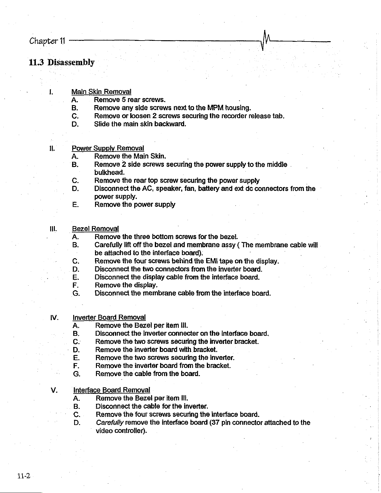
11.3
11
Disassembly
說
1.
Il
ill.
Main
Skin
A.
B
C.
D
Power
w>
Do
m
Bezel
WP
.
QaAMNMOO
Removal
Remove 5 rear
Remove
Remove
Slide
Supply
Remove
Remove 2 side
bulkhead.
Remove
Disconnect
power
Remove
any
or
the
main
Removal
the
the
supply.
the
loosen 2 screws
the
Removal
Remove
Carefully
be
Remove
Disconnect
Disconnect
Remove
Disconnect
the
lift
attached
the
the
off
to
the
the
the
screws.
side
screws
skin
backward.
Main
Skin.
screws
rear top
AC,
speaker,
power
three
four
supply
bottom
the
bezel
the
interface
screws
two
connectors
display
display.
membrane
next
securing
screw
screws
and
behind
cable
to
the
securing
.
the
securing
fan,
battery
for
membrane
board):
the
from
from
the
cable
from
MPM
housing.
the
recorder
power
the
EMI
the
power
and
the
bezel.
assy ( The
tape
inverter
supply
interface
the
interface
release
to
supply
ext
dc
on
the
board.
board.
tab.
the
middle
connectors
membrane
display.
board.
from
cable
the
will
-
11-2
IV.
V.
Inverter
onmuouP
interface
Remove
Disconnect
Remove
Remove
Remove
Remove
Remove
Remove
Disconnect
Remove
Carefully
pom?
©
video
Board
Removal!
the
the
the
the
the
the
Board
Removal
the
the
remove
controller).
Bezel
the
inverter
two
screws
inverter
two
screws
inverter
cable
Bezel
the
cable
four
screws
the
per
item
connecter
securing
board
securing
board
from
the
per
item
for
interface
Ili.
with
bracket.
from
the
board.
Ill.
the
inverter.
securing
board
on the
the
inverter
the
inverter.
bracket.
the
interface
(37
interface
pin
board.
bracket.
board.
connector
attached
to
the
y
Mechanical
Disassembly
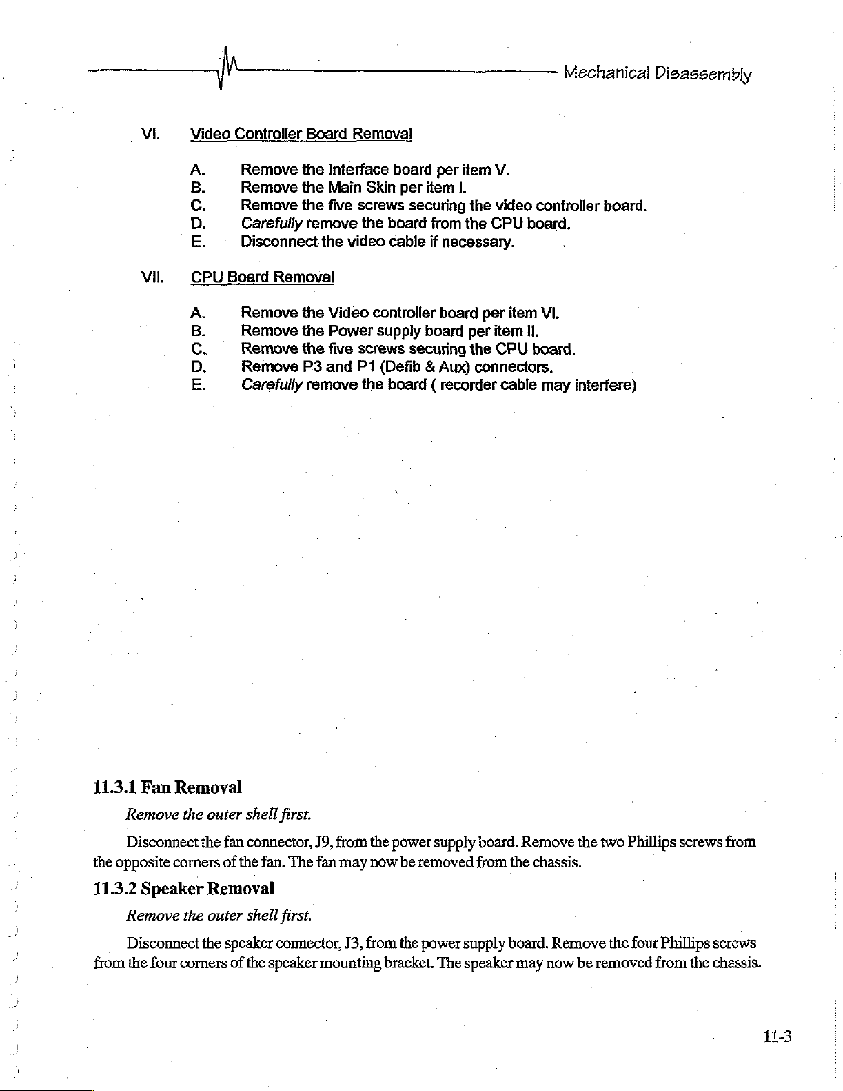
VI
VII.
Video
A.
B.
C.
D.
E.
CPU
A.
B.
C.
D.
E.
Controller
Remove
Remove
Remove
Carefully
Disconnect
Board
Removal
Remove
Remove
Remove
Remove
Carefully
Board
the
Interface
the
Main
the
five
remove
the
the
Video
the
Power
the
five
P3
and
remove
Removal
board
Skin
per item
screws
the
video
screws
P1
the
securing
board
cable
controller
supply
securing
(Defib & Aux)
board ( recorder
per
item
|.
the
from
the
if
necessary.
board
board
per
the
connectors.
V.
video
CPU
per
item
CPU
cable
controller
board.
item
VI.
II.
board.
may
board.
interfere)
41.3.1
Remove
Disconnect
the
opposite
11.3.2
Remove
Disconnect
from
the
Fan
Removal
the
corners
Speaker
the
four
corners
outer
shell
the
fan
connector,
of
the
Removal
outer
shell
the
speaker
of
the
first.
J9,
fan.
The
fan
first.
connector,
speaker
mounting
from
may
J3,
the
power
now
be
from
the
bracket,
supply
removed
power
The
supply
speaker
board.
from
the
board.
may
Remove
chassis.
Remove
now
the
two
be
removed
Phillips
the
four
screws
Phillips
from
screws
the
chassis.
from
11-3
Chapter
11
de
eres
BATTERY
>
OXF
CONNECIOR
: 1
À
x
i
2
4
42
FROM
VE
EK
Ay
CHE
3
|
ETS
>
usati
5
ge
paja
トー
ee
。
EE
1
3
I
了
gif
a
al
WU
Ps
CAG
E
ES
BET
一
A
CHASSIS
sp
rca
srt
SAR
iş
ASSEMBLY
asse
%
1997
|
11-4
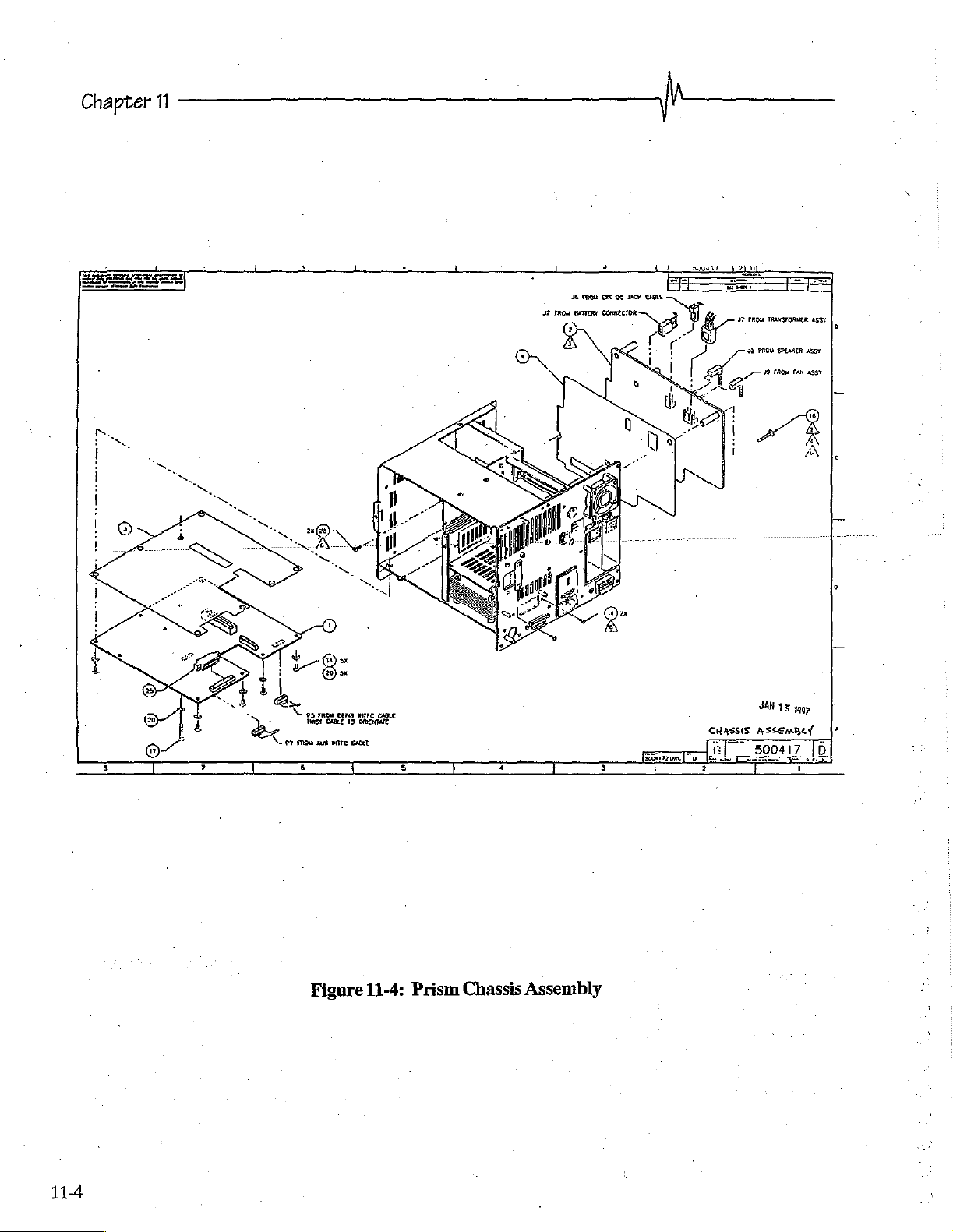
Figure
11-4:
Prism
Chassis
Assembly
|
Mechanical
Disassembly
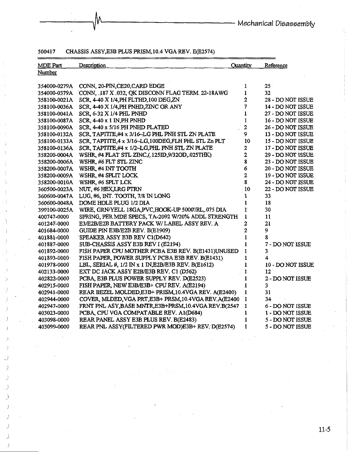
500417
MDE
Number
354000-0279A
354000-0379A
358100-0021A
358100-0036A
358100-0041A
358100-0087A
358100-0090A
358100-0132A
358100-0133A
358100-0136A
358200-0004A
358200-0006A - WSHR,
358200-0007A
358200-0009A
338200-0010A
360500-0023A . NUT,
360600-0047A
360600-0048A
399100-0025A
400747-0000
401247-0000
401684-0000
401331-0000
401887-0000
401892-0000
401893-0000
401978-0000
402133-0000
402822-0000
402915-0000
402941-0000
402944-0000
402947-0000
403023-0000
403098-0000
403099-0000
Part
CHASSIS
ASSY,E3B
Description,
CONN,
“CONN,
SCR,
SCR,
SCR,
SCR,
SCR,
SCR,
SCR,
SCR,
WSHR,
WSHR,
WSHR,
WSHR,
LUG,
DOME
WIRE,
SPRING,
E3/E2B/E2B
GUIDE
SPEAKER
SUB-CHASSIS
FISH
FISH
LBL,
EXT
PCBA,
FISH
REAR
COVER,
FRNT
PCBA,
REAR
REAR
PLUS
PRISM,
20-PIN,CE20,CARD
.187 X .032,
4-40 X 1/4,PH
4-40 X 1/4,PH
6-32 X 1/4
4-40x 1 IN,PH
4-40 x 5/16
TAPTITE,#4 x 3/16~LG
TAPTITE,4 x 3/16~LG,100DEG,FLH
TAPTITE,#4 x 1/2~LG,PHL
#4
FLAT
#6
FLT
#4
INT
#4
SPLIT
#6
SPLT
#6
HEX,LRG
#6,
INT.
HOLE
GRN/YELL
PER
BATTERY
PIN
E3B/E2B
ASSY
PAPER
PAPER,
SERIAL
DC
JACK
E3B
PLUS
PAPER,
BEZEL
QK
FLTHD,100
PNHD,ZINC
PHL
PNHD
PNHD
PH
PNHD
STL
ZINC,(.1251D,9/320D,.025THK)
STL
ZINC
TOOTH
LOCK
LCK
PTRN
TOOTH,
PLUG
MDE
CPU
1/2
18GA,PVC,HOOK-UP
SPECS,
REV.
E3B
REV
ASSY
E3B
MOTHER
POWER
#,
1/2
IN x 1
ASSY
E2B/E3B
POWER
NEW
E3B/E3B+
MOLDED,E3B+
MLDED,VGA
PNL
ASY,BASE
CPU
VGA
COMPATABLE
PANEL
PNL
ASSY
E3B
ASSY(FILTERED
10.4
VGA
EDGE
DISCONN
PLATED
7/8
INLONG
DIA
PACK
B(E1909)
C1(D642)
FLAG
DEG,ZN
OR
PHL
PNH
PNH
TA-2092
W/
LABEL
REV I (E2194)
PCBA
E3B
SUPPLY
PCBA
IN,E2B/E3B
REV.
SUPPLY
CPU
REV.
REV.
PRISM,10.4VGA
PRT,E3B+
PRSM,10.4VGA
MNTR,E3B+PRSM,10.4VGA
REV,
PLUS
REV.
PWR
MOD)E3B+
REV.
E(E2574)
TERM.
ANY
STL
ZN
PHL
STL
STL
ZN
PLATE
5000'7RL,.075
W/20%
C1
ADDL
ASSY
REV.
E3B
REV.
REV.
B(E1612)
(D562)
B(E1431)UNUSED
D(E2523)
A(E2194)
A1(D684)
B(E2483)
Quantity
22-18AWG
PLATE
Zn
PLT
DIA
STRENGTH
REV.
A
B(E1431)
REV.
A(E2400)
REV.A(E2400
REV.B(2547
REV.
D(E2574)
Reference
1
1
2
7
1
1
.
2
9
10
2
2
8
6
2
0
25
32
28 - DO
14 - DO
27 - DO
16 - DO
26 - DO
13 - DO
15 - DO
17 - DO
29 - DO NOT
23 - DO
20 - DO
19 - DO
24 - DO
22 - DO
33
18
30
11
2
9
8
7 - DO
3
4
10 - DO
12°
2-
3
31
34
6 - DO
1-
5 - DO
5 - DO NOT
DO
DO
NOT
NOT
NOT
NOT
NOT
NOT
NOT
NOT
NOT
NOT
NOT
NOT
NOT
NOT
NOT
NOT
NOT
NOT
NOT
ISSUE
ISSUE
ISSUE
ISSUE
ISSUE
ISSUE
ISSUE
ISSUE
ISSUE
ISSUE
ISSUE
ISSUE
ISSUE
ISSUE
ISSUE
ISSUE
ISSUE
ISSUE
ISSUE
ISSUE
ISSUE
11-5
 Loading...