

Page 1

Carbon Cortex-M3 Model
User Guide for
SoC Designer Plus
Carbon Model Version 4.0.0
For the ARM Cortex-M3 Processor
Silicon Version: r2p0
The Trusted Path to
The information contained in this document is confidential information of Carbon Design Systems, Inc.,
and may not be duplicated or disclosed to unauthorized and/or third parties.
Accuracy
™
Page 2

Copyright
Copyright © 2003-2013 Carbon Design Systems, Inc. All rights reserved.
Files, documents or portions thereof presented on the Carbon Design Systems Internet server “Publication”, permits persons to view, copy, and print the Publication subject to the following conditions:
• The Publication are to be kept strictly confidential
• Copies of the Publication will not be distributed
• Copies of the Publication must include the Carbon Design Systems copyright notice
• Carbon Design Systems logos may only be used with Carbon's expressed written permission, including but not limited to: linking through hyperlinks, electronic display, and print format.
Disclaimer of Warranty
This publication is provided “as is” without warranty of any kind, either expressed or implied, including, but not limited
to, the implied warranties of merchantability, fitness for a particular purpose, or non-infringement. Carbon Design Systems assumes no responsibility for errors or omissions in this publication or other documents which are referenced by or
linked to this publication.
References to corporations, their services and products, are provided “as is” without warranty of any kind, either
expressed or implied. In no event shall Carbon Design Systems be liable for any special, incidental, indirect or consequential damages of any kind, or any damages whatsoever, including, without limitation, those resulting from loss of
use, data or profits, whether or not advised of the possibility of damage, and on any theory of liability , arising out of or in
connection with the use or performance of this information.
This publication may include technical or other inaccuracies or typographical errors. Carbon Design Systems may make
improvements and/or changes in the product(s) and/or the program(s) described in this publication and in the publication
itself at any time.
Trademarks
© 2003-2013 Carbon Design Systems, Inc. All rights reserved. Carbon Design Systems, the Carbon Design Systems
logo, Carbon Model Studio, Replay, OnDemand, SoC Designer, Software Before Silicon, SOC-VSP, Swap & Play, VSP,
The Answer to Validation, and The Trusted Path to Accuracy are trademarks or registered trademarks of Carbon Design
Systems, Incorporated in the United States and/or other countries.
ARM, AMBA and RealView ar e registered trademarks of ARM Limited. AHB, APB and AXI are trademarks of ARM
Limited. “ARM” is used to represent ARM Holdings plc ; its operating company ARM Limited; and the regional subsidiaries ARM INC.; ARM KK; ARM Korea Ltd.; ARM T aiwan; ARM France SAS; ARM Consulting (Shanghai) Co.
Ltd.; ARM Belgium N.V.; ARM Embedded Technologies Pvt. Ltd.; and ARM Physical IP, Inc.
Microsoft, Windows 2000, and Wi ndows XP are trademarks or registered trademarks of Microsoft Corporation in the
United States and/or other countries.
SystemC is a trademark of the Open SystemC Initiative.
All other trademarks, registered trademarks, and products referenced herein are the property of their respective owners.
Carbon Design Systems, Inc. Confidential
Page 3

Technical Support
If you have questions or problems concerning Carbon software, contact Technical Support.
Phone Support Hours: Monday–Friday
9:00 am–5:00 pm EST
Carbon Design Systems, Inc.
125 Nagog Park
Acton, MA 01720
Voice: +1-978-264-7399
Asia: +81-3-5524-1288
Fax: +1-978-264-9990
Email: [email protected]
Web: www.carbondesignsystems.com
Voice mail is available after hours. You may also access our on-line feedback form any time from the Support page of
the Carbon web site.
Document revised August 2013.
Page 4

Carbon Design Systems, Inc. Confidential
Page 5

Contents
Chapter 1.
Using the Model Kit Component in SoC Designer Plus
Cortex-M3 Functionality . . . . . . . . . . . . . . . . . . . . . . . . . . . . . . . . . . . . . . . . . . . . . . . . . . . .1-1
Fully Functional and Accurate Features . . . . . . . . . . . . . . . . . . . . . . . . . . . . . . . . . . . . .1-2
Fully Functional and Approximate Features . . . . . . . . . . . . . . . . . . . . . . . . . . . . . . . . . .1-2
Hardware Features not Implemented . . . . . . . . . . . . . . . . . . . . . . . . . . . . . . . . . . . . . . . .1-2
Differences from the ARM RVML Model . . . . . . . . . . . . . . . . . . . . . . . . . . . . . . . . . . .1-3
Features Additional to the Hardware . . . . . . . . . . . . . . . . . . . . . . . . . . . . . . . . . . . . . . . .1-4
Adding and Configuring the SoC Designer Plus Component . . . . . . . . . . . . . . . . . . . . . . . .1-4
Carbon SoC Designer Plus Component Files . . . . . . . . . . . . . . . . . . . . . . . . . . . . . . . . .1-4
Adding the Carbon Model to the Component Library . . . . . . . . . . . . . . . . . . . . . . . . . .1-5
Adding the Component to the SoC Designer Canvas . . . . . . . . . . . . . . . . . . . . . . . . . . .1-6
Available Component ESL Ports . . . . . . . . . . . . . . . . . . . . . . . . . . . . . . . . . . . . . . . . . . . . . .1-6
Transaction Ports . . . . . . . . . . . . . . . . . . . . . . . . . . . . . . . . . . . . . . . . . . . . . . . . . . . . . . .1-8
Clock Ports . . . . . . . . . . . . . . . . . . . . . . . . . . . . . . . . . . . . . . . . . . . . . . . . . . . . . . . . . . .1-9
Setting Component Parameters . . . . . . . . . . . . . . . . . . . . . . . . . . . . . . . . . . . . . . . . . . . . . . .1-9
Debug Features . . . . . . . . . . . . . . . . . . . . . . . . . . . . . . . . . . . . . . . . . . . . . . . . . . . . . . . . . .1-12
Register Information . . . . . . . . . . . . . . . . . . . . . . . . . . . . . . . . . . . . . . . . . . . . . . . . . . .1-12
Run To Debug Point Feature . . . . . . . . . . . . . . . . . . . . . . . . . . . . . . . . . . . . . . . . . . . . .1-19
Memory Information . . . . . . . . . . . . . . . . . . . . . . . . . . . . . . . . . . . . . . . . . . . . . . . . . . .1-20
Disassembly View . . . . . . . . . . . . . . . . . . . . . . . . . . . . . . . . . . . . . . . . . . . . . . . . . . . . .1-20
Available Profiling Data . . . . . . . . . . . . . . . . . . . . . . . . . . . . . . . . . . . . . . . . . . . . . . . . . . . 1-21
Hardware Profiling . . . . . . . . . . . . . . . . . . . . . . . . . . . . . . . . . . . . . . . . . . . . . . . . . . . .1-21
Software Profiling . . . . . . . . . . . . . . . . . . . . . . . . . . . . . . . . . . . . . . . . . . . . . . . . . . . . .1-21
Carbon Design Systems, Inc. Confidential
Page 6

vi Contents
Carbon Design Systems, Inc. Confidential
Page 7

A Carbon Model component is a library developed from ARM intellectual property (IP)
that is generated through Carbon Model Studio™. The model then can be used within a
virtual platform tool, for example, Carbon SoC Designer Plus.
About This Guide
This guide provides all the information needed to configure and use the Carbon Cortex-
M3 Model in Carbon SoC Designer Plus.
Audience
This guide is intended for experienced hardware and software developers who create com-
ponents for use with Carbon SoC Designer Plus. You should be familiar with the follow-
ing products and technology:
• Carbon SoC Designer Plus
• Hardware design verification
• Verilog or VHDL programming language
Preface
Carbon Design Systems, Inc. Confidential
Page 8

viii Preface
Conventions
This guide uses the following conventions:
Convention Description Example
courier
Commands, functions,
variables, routines, and
code examples that are set
apart from ordinary text.
italic New or unusual words or
phrases appearing for the
first time.
bold Action that the user per-
forms.
<text> Values that you fill in, or
that the system automatically supplies.
[ text ] Square brackets [ ] indicate
optional text.
[ text1 | text2 ] The vertical bar | indicates
“OR,” meaning that you
can supply text1 or text 2.
Also note the following references:
sparseMem_t SparseMemCreateNew();
Transactors provid e the entry and exit
points for data ...
Click Close to close the dialog.
<platform>/ represents the name of
various platforms.
$CARBON_HOME/bin/modelstudio
[ <filename> ]
$CARBON_HOME/bin/modelstudio
[<name>.symtab.db |
<name>.ccfg ]
• References to C code implicitly apply to C++ as well.
• File names ending in .cc, .cpp, or .cxx indicate a C++ source file.
Carbon Design Systems, Inc. Confidential
Page 9

Preface ix
Further reading
This section lists related publications by Carbon and by third parties.
Carbon SoC Designer Plus Documentation
The following publications provide information that relate directly to SoC Designer Plus:
• Carbon SoC Designer Plus Installation Guide
• Carbon SoC Designer Plus User Guide
• Carbon SoC Designer Plus Standard Model Library Reference Manual
• Carbon SoC Designer Plus AHBv2 Protocol Bundle User Guide
External publications
The following publications provide reference information about ARM® products:
• Cortex-M3 Technical Reference Manual
• AMBA 3 AHB-Lite Overview
• AMBA Specification (Rev 2.0)
• AMBA AHB Transaction Level Modeling Specification
• Architecture Reference Manual
• ARM RealView Model Debugger User Guide
See http://infocenter.arm.com/help/index.jsp for access to ARM documentation.
The following publications provide additional information on simulation:
• IEEE 1666™ SystemC Language Reference Manual, (IEEE Standards Association)
• SPIRIT User Guide, Revision 1.2, SPIRIT Consortium.
Carbon Design Systems, Inc. Confidential
Page 10

x Preface
Glossary
AMBA Advanced Microcontr oller Bus Ar chitectur e. Th e ARM open standard on- chip
bus specification that describes a strategy for the interconnection and management of functional blocks that make up a System-on-Chip (SoC).
AHB Advanced High-performance Bus. A bus protocol with a fixed pipeline
between address/control and data phases. It only supports a subset of the functionality provided by the AMBA AXI protocol.
APB Advanced Peripheral Bus. A simpler bus protocol than AXI and AHB. It is
designed for use with ancillary or general-purpose peripherals such as timers,
interrupt controllers, UARTs, and I/O ports.
AXI Advanced eXtensible Interface. A bus protocol that is targeted at high perfor-
mance, high clock frequency system designs and includes a number of features that make it very suitable for high speed sub-micron interconnect.
Carbon Model A software object created by the Carbon Model Studio (or Carbon compiler)
from an RTL design. The Carbon Model contains a cycle- and register-accurate model of the hardware design.
Carbon Model
Studio
CASI ESL API Simulation Interface, is based on the SystemC communication
CADI ESL API Debug Interface, enables reading and writing memory and register
CAPI ESL API Profiling Interface, enables collecting historical data from a compo-
Component Building blocks used to create simulated systems. Components are connected
ESL Electronic System Level. A type of design and verification methodology that
HDL Hardware Description Language. A language for formal description of elec-
RTL Register Transfer Level. A high-level hardware description language (HDL)
SoC Designer The full name is Carbon SoC Designer Plus. A high-performance, cycle accu-
Carbon’s graphical tool for generating, validating, and executing hardwareaccurate software models. It creates a Carbon Model, and it also takes a Car-
bon Model as input and generates a Carbon component that can be used in
SoC Designer Plus, Platform Architect, or OSCI SystemC for simulation.
library and manages the interconnection of components and communication
between components.
values and also provides the interface to external debuggers.
nent and displaying the results in various formats.
together with unidirectional transaction-level or signal-level connections.
models the behavior of an entire system using a high-level language such as C
or C++.
tronic circuits, for example, Verilog or VHDL.
for defining digital circuits.
rate simulation framework which is targeted at System-on-a-Chip hardware
and software debug as well as architectural exploration.
SystemC SystemC is a single, unified design and verification language that enables ver-
ification at the system level, independent of any detailed hardware and software implementation, as well as enabling co-verification with RTL design.
Transactor Transaction adaptors. You add transactors to your Carbon component to con-
nect your component directly to transaction level interface ports for your particular platform.
Carbon Design Systems, Inc. Confidential
Page 11

Chapter 1
Using the Model Kit Component in
SoC Designer Plus
This chapter describes the functionality of the Model component, and how to use it in
Carbon SoC Designer Plus. It contains the following sections:
• Cortex-M3 Functionality
• Adding and Configuring the SoC Designer Plus Component
• Available Component ESL Ports
• Setting Component Parameters
• Debug Features
• Available Profiling Data
1.1 Cortex-M3 Functionality
The Cortex-M3 processor is a low-power processor that features low gate count, low inter-
rupt latency, and low-cost debug. It is intended for deeply embedded applications that
require fast interrupt response features. The processor implements the ARMv7-M archi-
tecture.
This section provides a summary of the functionality of the model compared to that of the
hardware, and the performance and accuracy of the model. For details of the functionality
of the hardware that the model simulates, see the Cortex-M3 Technical Reference Manual.
• Fully Functional and Accurate Features
• Fully Functional and Approximate Features
• Hardware Features not Implemented
• Differences from the ARM RVML Model
• Features Additional to the Hardware
Carbon Design Systems, Inc. Confidential
Page 12

1-2 Using the Model Kit Component in SoC Designer Plus
1.1.1 Fully Functional and Accurate Features
The following features of the Cortex-M3 hardware are fully implemented in the Cortex-
M3 model:
• Cortex-M3 Integer Core
• NVIC – Nested Vectored Interrupt Controller
• WIC – Wakeup Interrupt Controller
• AHB-Lite: ICode, DCode, and System Bus Interfaces
• APB v3.0 interface for accessing the external Private Peripheral Bus
• FPB – Flash Patch and Debug
• DWT – Debug Watchpoint and Trace
• MPU – Memory Protection Unit
• BusMatrix (including Unaligned and Bit-Banding)
•ROM Table
1.1.2 Fully Functional and Approximate Features
The following features of the Cortex-M3 hardware are implemented in the Cortex-M3
model, but the exact behavior of the hardware implementation is not accurately repro-
duced because some approximations and optimizations have been made for simulation
performance:
• ROM Table. The ROM Table contains entries for ITM, TPIU, and ETM, even though
these components are not modeled.
• FAULT Handling. All faults are functionally handled, but there may be cycle inaccuracies.
Note on Clock-gating.
The Cortex-M3 supports architectural clock-gating only. This is controlled by setting the
CLKGATE_PRESENT parameter to 1 in the default.conf configuration file before creating
the Model. See the Cortex-M3 Configuration and Sign-off Guide for more information.
The Carbon Model does not currently support RTL clock-gating.
1.1.3 Hardware Features not Implemented
The following features of the Cortex-M3 hardware are not implemented in the Cortex-M3
model:
• SW/JTAG-DP
•ITM
• ETM
• TPIU
• AHB-AP
Carbon Design Systems, Inc. Confidential
Page 13

Cortex-M3 Functionality 1-3
• Current Priority Output
• RTL clock-gating
• The following registers are not available to be read / written via debug transactions —
for example, in the SoC Designer Plus Registers window, or by accessing them
directly from RealView Debugger:
– Core register: PRI_ISR, PRIMASK, BASEPRI, FAULTMASK, CONTROL,
CURRPRI
– NVIC register: CprAccess, SoftwareInt
– Debug register: DebugCoreRegisterTransferSelector
– Pipeline register: not supported
– Stats register: not supported
The functionality of these registers, however, does exist and can be accessed by soft-
ware running on the virtual platform.
1.1.4 Differences from the ARM RVML Model
The following differences exist between the Carbon Model and the older ARM® RealV iew® Model Library model.
• The Carbon model uses the AHB-Lite v2 port interface instead of the AHB v1 interface used by the RVML model.
• No software profiling is available.
• When using semihosting you must use the semihost component from Carbon. This
“CarbonSemihost” component is included in the Carbon SoC Designer Plus Standard
Model Library , version 3.0 or greater. The ARM R VML semihost component will not
work with the Carbon Model.
• Differences in component ports:
– The RVML component treats the systickClkIn port like a clock and defines it as a
clock input. Based on the Cortex-M3 Technical Reference Manual, this should not
be a clock, so the Carbon Model treats it like a slave port.
– The following ports are not available in the Carbon Model: WAKEUP,
WAKEUPEN, WICSENSE, and semihostbus.
– The following ports have been added to the Carbon Model: extSemi.
• Differences in component parameters:
– The following parameters are not available in the Carbon Model: CodeSpace
block size, SystemSpace block size, external PPB block size, enable tracing,
enable WIC, SemiHosting parameters, LvlWidth, NumIRQ, profiling ALU/LSU
CPI, Tracing parameters, and use MME parameters.
– The following parameters have been added to the Carbon Model: DNOTITRANS,
Enable PC Tracing, and PC Tracing File.
• Only the Core Events profiling stream is supported; all other streams from the RVML
model are not profiled.
Carbon Design Systems, Inc. Confidential
Page 14

1-4 Using the Model Kit Component in SoC Designer Plus
1.1.5 Features Additional to the Hardware
The following features that are implemented in the Cortex-M3 model to enhance usability
do not exist in the Cortex-M3 hardware:
• Semihosting Support. Semihosting enables the target application to communicate with
the host operating system. This is used for external time synchronization, file handling
operations, console input/output, and similar functionality.
• Debug and Profiling. For more information about debug and profiling features, refer
to the sections Debug Features and Available Profiling Data, respectively.
• The “run to debug point” feature has been added. This feature forces the debugger to
advance the processor to the debug state instead of having the model get into a nondebuggable state. See “Run To Debug Point Feature” on page 1-19 for more informa-
tion.
1.2 Adding and Configuring the SoC Designer Plus Component
The following topics briefly describe how to use the component. See the Carbon SoC
Designer Plus User Guide for more information.
• Carbon SoC Designer Plus Component Files
• Adding the Carbon Model to the Component Library
• Adding the Component to the SoC Designer Canvas
1.2.1 Carbon SoC Designer Plus Component Files
The component files are the final output from the Carbon Model Studio compile and are
the input to SoC Designer Plus. There are two versions of the component; an optimized
release version for normal operation, and a debug version.
On Linux, the debug version of the component is compiled without optimizations and
includes debug symbols for use with gdb. The release version is compiled without debug
information and is optimized for performance.
On Windows, the debug version of the component is compiled referencing the de bug runtime libraries so it can be linked with the debug version of SoC Designer Plus. The release
version is compiled referencing the release runtime library. Both release and debug versions generate debug symbols for use with the Visual C++ debugger on Windows.
Carbon Design Systems, Inc. Confidential
Page 15

Adding and Configuring the SoC Designer Plus Component 1-5
The provided component files are listed below:
Table 1-1 Carbon SoC Designer Plus Component Files
Platform File Description
Linux maxlib.lib<model_name>.conf
lib<component_name>.mx.so
lib<component_name>.mx_DBG.so
Windows maxlib.lib<model_name>.windows.conf
lib<component_name>.mx.dll
lib<component_name>.mx_DBG.dll
SoC Designer Plus configuration file
SoC Designer Plus component runtime file
SoC Designer Plus component debug file
SoC Designer Plus configuration file
SoC Designer Plus component runtime file
SoC Designer Plus component debug file
Additionally, this User Guide PDF file and a ReadMe text file are provided with the component.
1.2.2 Adding the Carbon Model to the Component Library
The compiled Carbon Model component is provided as a configuration file (.conf). To
make the component available in the Component Window in SoC Designer Canvas, perform the following steps:
1. Launch SoC Designer Canvas.
2. From the File menu, select Preferences.
3. Click on Component Library in the list on the left.
4. Under the Additional Component Configuration Files window, click Add.
5. Browse to the location where the SoC Designer Plus model is located and select the
component configuration file:
–
maxlib.lib<model_name>.conf (for Linux)
–
maxlib.lib<model_name>.windows.conf (for Windows)
6. Click OK.
7. To save the preference s permanently, click the OK & Save button.
The component is now available from the SoC Designer Plus Component Window.
Carbon Design Systems, Inc. Confidential
Page 16
1-6 Using the Model Kit Component in SoC Designer Plus
1.2.3 Adding the Component to the SoC Designer Canvas
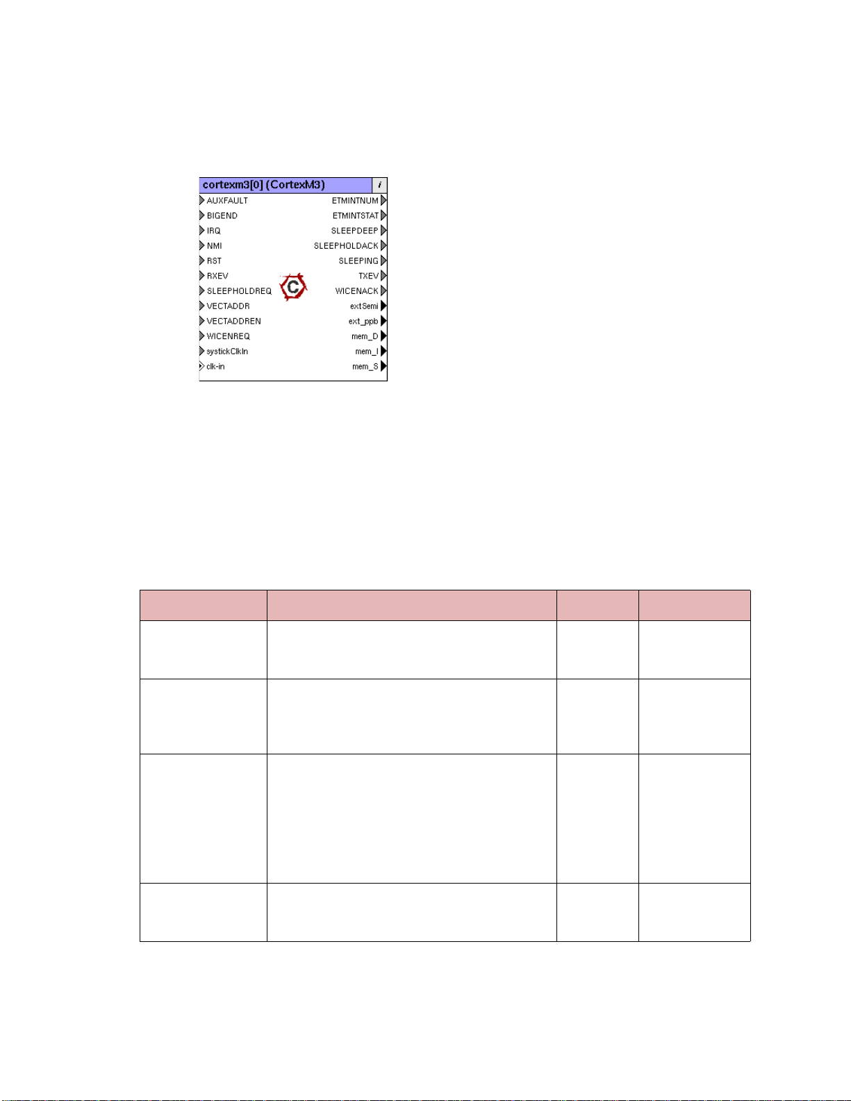
Locate the component in the Component Window and drag it out to the Canvas. It will
appear as shown in Figure 1-1.
Figure 1-1 Cortex-M3 Components in SoC Designer Plus
Additional ports are provided depending on the model RTL configuration file,
default.conf, used to create the Model.
1.3 Available Component ESL Ports
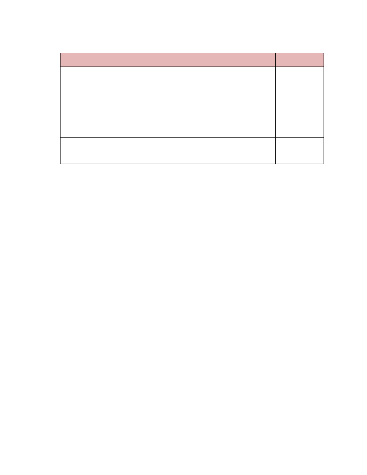
Table 1-2 describes the ESL ports that are exposed in SoC Designer Plus. See the CortexM3 Technical Reference Manual for more information.
Table 1-2 ESL Component Ports
ESL Port Description Direction Type
AUXFAULT Auxiliary fault status information. It is the input to
AFSR (Auxiliary Fault Status Register in NVIC),
where value = fault number (0-31).
BIGEND This port indicates the endianness; where 1=big
endian and 0=little endian. It changes the BIG-
END component parameter value. Note that this
configuration is only latched during core reset.
IRQ This port connects to external interrupt signals. It
can be anywhere from 1 to 240 bits wide based on
the configuration used to create the Model.
The value must indicate the interrupt number
[NumIRQ..0] and the *extValue must indicate
whether the IRQ line is asserted (*extValue=1) or
deasserted (*extValue=0).
NMI Non-maskable interrupt input to the NVIC; where
1 is used to assert NMI, and 0 is used to deassert
NMI request.
Input Signal slave
Input Signal slave
Input Signal slave
Input Signal slave
Carbon Design Systems, Inc. Confidential
Page 17

Available Component ESL Ports 1-7
Table 1-2 ESL Component Ports (Continued)
ESL Port Description Direction Type
RST This port is the core input reset. *extValue indi-
cates the type of reset:
*extValue=1 indicates a PORESET
*extValue=0 indicates a SYSRESET.
value is the signal value on the reset line. Note
value is active high (instead of active low reset
used in the hardware). Also note the reset request
is ignored if *extValue is NULL.
RXEV Causes a wakeup from a WFE instruction. Input Signal slave
SLEEPHOLDREQ Request to extend sleep mode. Input Signal slave
VECTADDR Reserved Input Signal slave
VECTADDREN Reserved Input Signal slave
WICENREQ Make SLEEPDEEP mode WIC mode sleep
request from PMU.
systickClkIn
clk-in Input Clock port. This port must be explicitly con-
ETMINTNUM The interrupt number of the current execution
System Tick Clock. See
page 1-9 for more information.
nected to a clock master.
context.
“Clock Ports” on
Input Signal slave
Input Signal slave
Input Signal slave
Input Clock Generator
Output Signal master
ETMINTSTAT Interrupt status of the current cycle:
000 - no status
001 - interrupt entry
010 - interrupt exit
011 - interrupt return
100 - vector fetch and stack push
SLEEPDEEP Indication of core going into SLEEPDEEP mode;
where 1 is used when going into SLEEPDEEP,
and 0 is used when the core is waken up.
SLEEPHOLDACK Acknowledges signal for SLEEPHOLDREQ that
the core will be held in sleep mode.
SLEEPING Indication that the core is going into SLEEP mode
(because of WFE/WFI). The value 1 is used when
the core goes into SLEEP mode, and 0 when the
core is waken up.
TXEV Event transmitted as a result of SEV instruction. Output Signal master
WICENACK Active high SLEEPDEEP is WICSLEEP
acknowledgement to PMU.
extSemi Semihosting can be enabled by connecting this
port to the SoC Designer Plus semihost compo-
nent, contained in the Carbon SoC Designer Plus
Standard Model Library (v3.0 or greater).
Output Signal master
Output Signal master
Output Signal master
Output Signal master
Output Signal master
Output Transaction mas-
ter
Carbon Design Systems, Inc. Confidential
Page 18
1-8 Using the Model Kit Component in SoC Designer Plus
Table 1-2 ESL Component Ports (Continued)
ESL Port Description Direction Type
ext_ppb Private Peripheral Bus Interface. This bus master
port implements the APB (v3.0) interface on the
Cortex-M3 for accessing peripherals mapped in
the external Private Peripheral Bus (PPB) region.
mem_D
DCode Interface. See
Master Ports”
mem_I
ICode Interface. See
Master Ports”
mem_S
System Bus Interface. See
tion Master Ports”
mation.
All pins that are not listed in this table have been either tied or disconnected for performance reasons.
Note: Some ESL component port values can be set using a component parameter. This
includes the BIGEND port. In those cases, the parameter value will be used whenever the ESL port is not connected. If the port is connected, the connection value
takes precedence over the parameter value.
1.3.1 Transaction Ports
“AHB-Lite Transaction
on page 1-8 for more information.
“AHB-Lite Transaction
on page 1-8 for more information.
“AHB-Lite Transac-
on page 1-8 for more infor-
Output APB Transaction
master
Output AHB-Lite Trans-
action master
Output AHB-Lite Trans-
action master
Output AHB-Lite Trans-
action master
1.3.1.1 AHB-Lite Transaction Master Ports
The mem_I, mem_D, and mem_S transaction master ports implement the AMBA AHBLite interface for the ICode, DCode, and System bus, respectively. These transaction master ports should be connected to AHBv2 slaves using either an MxAHBv2 bus component
(where one side is an AHB Lite Master and the other side is an AHB Lite Slave) or a
PL301 in between. See the SoC Designer Plus AHBv2 Protocol Bundle User Guide for
more information.
There are a few AHBv2 sideband signals defined specifically for the Cortex-M3. See the
AHBv2 Protocol Bundle User Guide for details on AHB Cortex-M3 extension signals.
1.3.1.2 ext_ppb Bus Master Port
The ext_ppb bus master port implements the APB v3.0 interface on the Cortex-M3 for
accessing peripherals mapped in the external Private Peripheral Bus (PPB) region. Data
accesses to an address mapped to the external PPB space (0xE0040000 to 0xE00FFFFF)
goes through this port, except for accesses to the ROM Table that is internal to the CortexM3 model.
Note: Address range seen by the ext_ppb port is fr om 0x40000 to 0xFEFF F (as opposed
to 0xE00FFFFF to 0xE00FEFFF), i.e., the upper 12 bits are unused. Consequently, when defining the address map for peripheral components in the external
peripheral space, the upper 12 bits of base address should be set to zero.
Carbon Design Systems, Inc. Confidential
Page 19
Setting Component Parameters 1-9
1.3.2 Clock Ports
clk_in is the clock port used to clock the core. The systickClkIn port can be used to c lock
the system tick timer. Note that the CLKSOURCE bit in the Systick control and status register of the NVIC has to be set to ‘1’ if the internal core clock is used to clock the system
tick timer, or ‘0’ if an external clock source is used. The reset value of CLKSOURCE bit
is ‘0’.
1.4 Setting Component Parameters
You can change the settings of all the component parameters in SoC Designer Canvas, and
of some of the parameters in SoC Designer Simulator. To modify the Carbon component’ s
parameters:
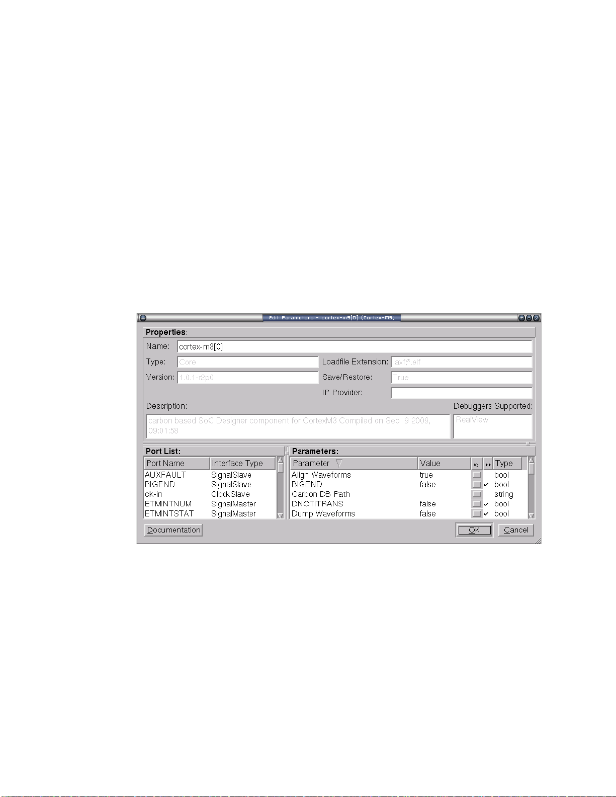
1. In the Canvas, right-click on the Carbon component and select Component Informa-
tion. You can also double-click the component. The Edit Parameters dialog box
appears.
Figure 1-2 Component Parameters Dialog Box
The list of available parameters will be slightly different depending on the settings that
you enabled in the configuration file (default.conf) when creating the component.
2. In the Parameters window, double-click the Value field of the parameter that you
want to modify.
Carbon Design Systems, Inc. Confidential
Page 20

1-10 Using the Model Kit Component in SoC Designer Plus
3. If it is a text field, type a new value in the Value field. If a menu choice is offered,
select the desired option. The parameters are described in Table 1-3.
Table 1-3 Component Parameters
Name Description
Align Waveforms When set to true, waveforms dumped
from the Carbon component are aligned
with the SoC Designer Plus simulation
time. The reset sequence, however, is not
included in the dumped data.
When set to false, the reset sequence is
dumped to the waveform data, however,
the Carbon component time is not
aligned with the SoC Designer Plus time.
BIGEND When set to true, configures the proces-
sor in big endian mode. Otherwise it
works in little endian mode (default).
Carbon DB Path Sets the directory path to the Carbon
database file.
DNOTITRANS When set to true, it disallows transac-
tions on the I and D interfaces at the
same time.
Dump Waveforms Determines whether SoC Designer Plus
dumps waveforms for this component.
Allowed
Values
true, false true No
true, false false Yes
Not Used empty No
true, false false Yes
true, false false Yes
Default Value
Runtime
1
Enable Debug
Messages
Enable PC Tracing Enables dumping a PC trace to disk con-
ext_ppb Enable
Debug Messages
ext_ppb PReady
Default High
mem_D Align Data Determines whether halfword and byte
mem_D Big Endian Determines whether AHB data is treated
mem_D Enable
Debug Messages
Determines whether debug messages are
logged for the component.
taining decode PCs and actual branch
PCs. See
page 1-21 for more information.
Determines whether debug messages are
logged for the ext_ppb port.
The transfer is extended if PREADY is
held low during an access phase.
transactions will align data to the transaction size for this port. By default, data
is not aligned.
as big endian for this port. By default,
data is not sent as big endian.
Determines whether debug messages are
logged for the mem_D port.
“Software Profiling” on
true, false false Yes
true, false false No
true, false false Yes
true, false true Yes
true, false false No
true, false false No
true, false false Yes
Carbon Design Systems, Inc. Confidential
Page 21

Setting Component Parameters 1-11
Table 1-3 Component Parameters (Continued)
Name Description
mem_I Align Data Determines whether halfword and byte
transactions will align data to the transaction size for this port. By default, data
is not aligned.
mem_I Big Endian Determines whether AHB data is treated
as big endian for this port. By default,
data is not sent as big endian.
mem_I Enable Debug
Messages
Determines whether debug messages are
logged for the mem_I port.
mem_S Align Data Determines whether halfword and byte
transactions will align data to the transaction size for this port. By default, data
is not aligned.
mem_S Big Endian Determines whether AHB data is treated
as big endian for this port. By default,
data is not sent as big endian.
mem_S Enable Debug
Messages
Determines whether debug messages are
logged for the mem_S port.
PC Tracing File When Enable PC Tracin g is enabled,
this is the file in which the PC trace
information is written. The data is written in binary format. The C++ file
pctracedump.cpp can be used to decode
the data.
Waveform File
2
Name of the waveform file. string CortexM3.fsdb No
Allowed
Values
Default Value
Runtime
true, false false No
true, false false No
true, false false Yes
true, false false No
true, false false No
true, false false Yes
Valid file
CortexM3PC.datNo
name
1
Waveform Timescale Sets the timescale to be used in the
waveform.
1. Yes means the parameter can be dynamically changed during simulation, No means it can be changed only
when building the system, Reset means it can be changed during simulation, but its new value will be taken
into account only at the next reset.
2. When enabled, SoC Designer Plus writes accumulated waveforms to the waveform file in the following situations: when the waveform buffer fills, when validation is paused and when validation finishes, and at the
end of each validation run.
Carbon Design Systems, Inc. Confidential
Many values
in drop-down
1 ns No
Page 22
1-12 Using the Model Kit Component in SoC Designer Plus
1.5 Debug Features
The Cortex-M3 model has a debug interface (CADI) that allows the user to view, manipulate, and control the registers and memory, and display disassembly for programs running
on the model in the SoC Designer Plus simulator or any d ebugger that supports CADI, for
example Model Debugger. A view can be accessed in SoC Designer Simulator by right
clicking on the model and choosing the appropriate menu entry.
• Register Information
• Run To Debug Point Feature
• Memory Information
• Disassembly View
1.5.1 Register Information
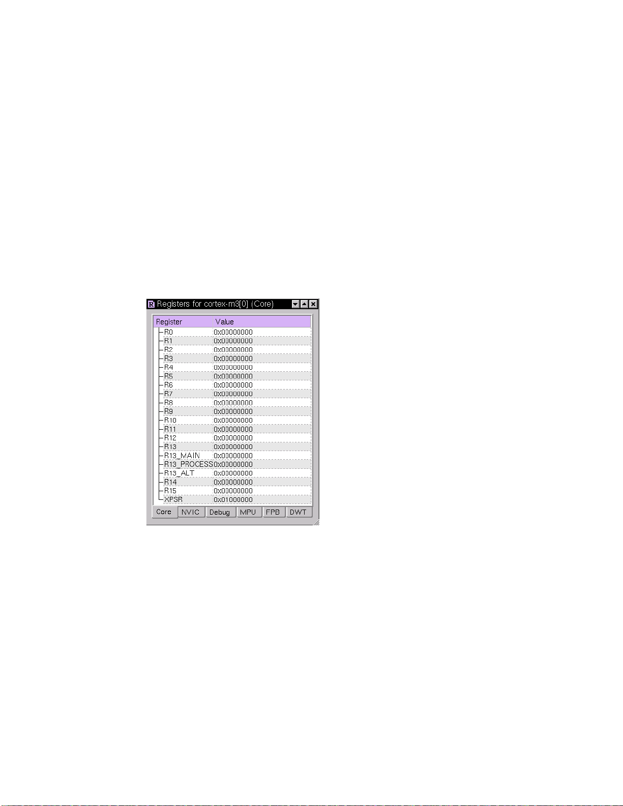
Figure 1-3 shows the Register view of the Cortex-M3 model in SoC Designer Simulator.
Figure 1-3 Cortex-M3 Registers View
The Cortex-M3 model has many sets of registers that are acc essible via the debug interface. Registers are grouped into sets according to functional area.
• Core Registers
• NVIC Registers
• Debug Registers
• MPU Registers
• FPB Registers
• DWT Registers
See the Cortex-M3 Technical Reference Manual for detailed descriptions of these regis-
ters.
Carbon Design Systems, Inc. Confidential
Page 23

Debug Features 1-13
1.5.1.1 Core Registers
The Core group contains the ARM Architectural registers.
Table 1-4 Core Registers
Name Description Type
R0 R0 register
R1 R1 register
R2 R2 register
R3 R3 register
R4 R4 register
R5 R5 register
R6 R6 register
R7 R7 register
R8 R8 register
R9 R9 register
R10 R10 register
R11 R11 register
R12 R12 register
R13 R13/Stack Pointer (SP) register
R13_MAIN R13_MAIN_MSP register
R13_PROCESS R13_PROCESS_PSP register
R13_ALT R13_ALT register
R14 R14/Link Register (LR)
R15 R15/PC (Program Counter) Register
read-write
read-write
read-write
read-write
read-write
read-write
read-write
read-write
read-write
read-write
read-write
read-write
read-write
read-write
read-write
read-write
read-write
read-write
read-write
XPSR Program Status Register read-write
1
1
1
1
1
1
1
1
1
1
1
1
1
1
1
1
1
1
1
1. Writeable at debuggable point only. Otherwise, a warning is printed.
Carbon Design Systems, Inc. Confidential
Page 24

1-14 Using the Model Kit Component in SoC Designer Plus
1.5.1.2 NVIC Registers
The NVIC group provides access to the interrupt controller state.
Table 1-5 NVIC Registers
Name Description Type
IntControlType Int Control Type register 0xE000E004 read-only
AuxControl Aux Control register 0xE000E008 read-write
SysTickControlAnd
Status
Sys Tick Control And Status register
0xE000E010
read-write
SysTickReloadValue Sys Tick Reload Value register 0xE000E014 read-write
SysTickCurrentValue Sys Tick Current Value register 0xE000E018 read-only
SysTickCalibration
Sys Tick Calibration Value register 0xE000E01C read-only
Value
SetEnable0_31 Set Enable0_31 register 0xE000E100 read-write (write does a
set enable)
SetEnable32_63
1
Set Enable32_63 register 0xE000E104 read-write (write does a
set enable)
SetEnable64_95
1
Set Enable64_95 register 0xE000E108 read-write (write does a
set enable)
SetEnable96_127
1
Set Enable96_127 register 0xE000E10C read-write (write does a
set enable)
1
SetEnable128_159
Set Enable128_159 register 0xE000E110 read-write (write does a
set enable)
1
SetEnable160_191
Set Enable160_191 register 0xE000E114 read-write (write does a
set enable)
1
SetEnable192_223
Set Enable192_223 register 0xE000E118 read-write (write does a
set enable)
1
SetEnable224_239
Set Enable224_239 register 0xE000E11C read-write (write does a
set enable)
ClearEnable0_31 Clear Enable0_31 register 0xE000E180 read-write (write does a
clear enable)
1
ClearEnable32_63
Clear Enable32_63 register 0xE000E184 read-write (write does a
clear enable)
1
ClearEnable64_95
Clear Enable64_95 register 0xE000E188 read-write (write does a
clear enable)
1
ClearEnable96_127
Clear Enable96_127 register 0xE000E18C read-wri te (write does a
clear enable)
1
ClearEnable128_159
Clear Enable128_159 register 0xE000E190 read-write (write does a
clear enable)
1
ClearEnable160_191
Clear Enable160_191 register 0xE000E194 read-write (write does a
clear enable)
Carbon Design Systems, Inc. Confidential
Page 25

Debug Features 1-15
Table 1-5 NVIC Registers (Continued)
Name Description Type
1
ClearEnable192_223
ClearEnable224_239
SetPend0_31 Set Pend0_31 register 0xE000E200 read-write (write does a
SetPend32_63
SetPend64_95
SetPend96_127
SetPend128_159
SetPend160_191
SetPend192_223
SetPend224_239
1
1
1
1
1
1
1
Clear Enable192_223 register 0xE000E198 read-write (write does a
clear enable)
1
Clear Enable224_239 register 0xE000E19C read-write (write does a
clear enable)
set pend)
Set Pend32_63 register 0xE000E204 read-write (write does a
set pend)
Set Pend64_95 register 0xE000E208 read-write (write does a
set pend)
Set Pend96_127 register 0xE000E20C read-write (write does a
set pend)
Set Pend128_159 register 0xE000E210 read-write (write does a
set pend)
Set Pend160_191 register 0xE000E214 read-write (write does a
set pend)
Set Pend192_223 register 0xE000E218 read-write (write does a
set pend)
Set Pend224_239 register 0xE000E21C read-write (write does a
set pend)
ClearPend0_31 Clear Pend0_31 reg ister 0xE000E280 read-write (write does a
clear pend)
ClearPend32_63
1
Clear Pend32_63 register 0xE000E284 read-write (write does a
clear pend)
ClearPend64_95
1
Clear Pend64_95 register 0xE000E288 read-write (write does a
clear pend)
ClearPend96_127
1
Clear Pend96_127 register 0xE000E28C read-write (write does a
clear pend)
1
ClearPend128_159
Clear Pend128_159 register 0xE000E290 read-write (write does a
clear pend)
1
ClearPend160_191
Clear Pend160_191 register 0xE000E294 read-write (write does a
clear pend)
1
ClearPend192_223
Clear Pend192_223 register 0xE000E298 read-write (write does a
clear pend)
1
ClearPend224_239
Clear Pend224_239 register 0xE000E29C read-write (write does a
clear pend)
ActiveBit0_31 Active Bit0_31 register 0xE000E300 read-only
ActiveBit32_63
ActiveBit64_95
1
1
Active Bit32_63 register 0xE000E304 read-only
Active Bit64_95 register 0xE000E308 read-only
Carbon Design Systems, Inc. Confidential
Page 26

1-16 Using the Model Kit Component in SoC Designer Plus
Table 1-5 NVIC Registers (Continued)
Name Description Type
ActiveBit96_127
ActiveBit128_159
ActiveBit160_191
ActiveBit192_223
ActiveBit224_239
1
Active Bit96_127 register 0xE000E30C read-only
1
Active Bit128_159 register 0xE000E310 read-only
1
Active Bit160_191 register 0xE000E314 read-only
1
Active Bit192_223 register 0xE000E318 read-only
1
Active Bit224_239 register 0xE000E31C read-only
Priority0_3 Priority Level Register 0-3 read-write
Priority4_7 Priority Level Register 4-7 read-write
Priority8_11 Priority Level Register 8-11 read-write
Priority12_15 Priority Level Register 12-15 read-write
CPUIDBase CPUID Base register 0xE000ED00 read-only
IntControlState Int Control State register 0xE000ED04 read-write
VectorTableOffset Vector Table Offset register 0xE000ED08 read-write
ApplicationInterrupt
ResetControl
Application Interrupt Reset Control register
0xE000ED0C
read-write
SystemControl System Control register 0xE000ED10 read-write
ConfigCtrl Config Control register 0xE000ED14 read-write
SysHandlerPri4_7 System Handlers 4-7 Priority register read-write
SysHandlerPri8_11 System Handlers 8-11 Priority register read-write
SysHandlerPri12_15 System Handlers 12-15 Priority register read-write
SystemHandlerControl
AndState
System Handler Control And State register
0xE000ED24
read-write
ConfigFSR Config FSR register 0xE000ED28 read-only
HFSR HFSR register 0xE000ED2C read-only
DebugStatus Debug Status register 0xE000ED30 read-only
MemManageAddress Memory Manage Address register 0xE000ED34 read-only
BusFaultAddress Bus Fault Address register 0xE000ED38 read-only
AuxFaultStatus Auxiliary Fault Status register 0xE000ED3C read-only
ProcessorFeature0 Processo r Feature 0 register 0xE000ED40 read-only
ProcessorFeature1 Processo r Feature 1 register 0xE000ED44 read-only
DebugFeature Debug Feature register 0xE000ED48 read-only
AuxiliaryFeature Auxiliary Feature register 0xE000ED4C read-only
MemoryModelFeature0 Memory Model Feature 0 register 0xE000ED50 read-only
MemoryModelFeature1 Memory Model Feature 1 register 0xE000ED54 read-only
Carbon Design Systems, Inc. Confidential
Page 27
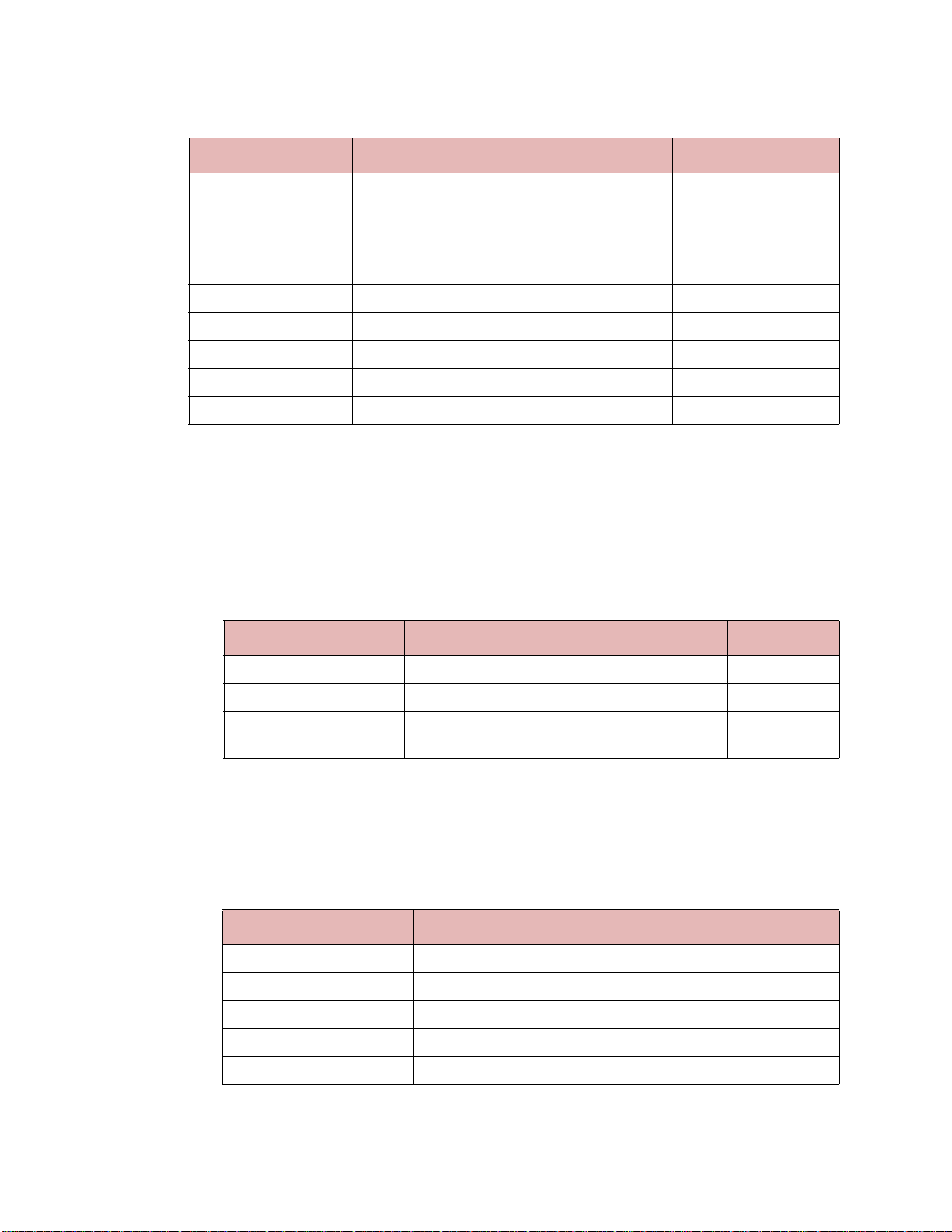
Debug Features 1-17
Table 1-5 NVIC Registers (Continued)
Name Description Type
MemoryModelFeature2 Memory Model Feature 2 register 0xE000ED58 read-only
MemoryModelFeature3 Memory Model Feature 3 register 0xE000ED5C read-only
ISAFeature0 ISA Feature 0 register 0xE000ED60 read-only
ISAFeature1 ISA Feature 1 register 0xE000ED64 read-only
ISAFeature2 ISA Feature 2 register 0xE000ED68 read-only
ISAFeature3 ISA Feature 3 register 0xE000ED6C read-only
ISAFeature4 ISA Feature 4 register 0xE000ED70 read-only
Nvic_PERIPHID[0-7] Nvic_PERIPHID 0 through 7 registers read-only
Nvic_PCELLID[0-3] Nvic_PCELLID 0 through 3 registers read-only
1. This register is available only if it was defined in the configuration when the model was built.
1.5.1.3 Debug Registers
The Debug group contains information about the control coprocessor register, CP15. This
register implements a range of control functions and provides status information for the
Cortex-M3 Multiprocessor.
Table 1-6 Debug Registers
Name Description Type
DebugControlStatus Debug Control Status register read-only
DebugCoreRegisterData Debug Core Register Data register read-write
DebugExceptionAnd
MonitorControl
1.5.1.4 MPU Registers
The MPU group contains registers for the Memory Protection Unit. It is only present if the
MPU is enabled.
Table 1-7 MPU Registers
Name Description Type
MPUT ype MPU Type register read-only
Debug Exception And Monitor Control register read-write
MPUControl MPU Control register read-write
MPURegionNumber MPU Region Number register read-write
MPUBaseAddr MPU Base Address register read-write
MPURegionAtribute MPU Region Attribute register read-write
Carbon Design Systems, Inc. Confidential
Page 28

1-18 Using the Model Kit Component in SoC Designer Plus
1.5.1.5 FPB Registers
The FPB group contains registers pertaining to the hardware breakpoints.
Table 1-8 FPB Registers
Name Description Type
FP_CTRL FP_CTRL register read-write
FP_REMAP FP_REMAP register read-write
FP_COMP[0-7] FP_COMP 0-7 Registers read-write
FPB_PERIPHID[0-7] FPB_PERIPHID 0-7 Registers read-write
FPB_PLCELLID[0-3] FPB_PCELLID 0-3 Registers read-write
1.5.1.6 DWT Registers
The DWT group contains registers pertaining to hardware watchpoints.
Table 1-9 DWT Registers
Name Description Type
DWT_CTRL DWT_CTRL register read-write
DWT_CYCCNT DWT_CYCCNT register read-write
DWT_CPICNT DWT_CPICNT register read-write
DWT_EXECNT DWT_EXECNT register read-write
DWT_SLEEPCNT DWT_SLEEPCNT register read-write
DWT_LSUCNT DWT_LSUCNT register read-write
DWT_FOLDCNT DWT_FOLDCNT register read-write
DWT_PCSR DWT_PCSR register read-write
DWT_COMP0 DWT Comparator 0 register read-write
DWT_MASK0 DWT Mask 0 register read-write
DWT_FUNCTION0 DWT Function 0 register read-write
DWT_COMP1 DWT Comparator 1 register read-write
DWT_MASK1 DWT Mask 1 register read-write
DWT_FUNCTION1 DWT Function 1 register read-write
DWT_COMP2 DWT Comparator 2 register read-write
DWT_MASK2 DWT Mask 2 register read-write
DWT_FUNCTION2 DWT Function 2 register read-write
DWT_COMP3 DWT Comparator 3 register read-write
DWT_MASK3 DWT Mask 3 register read-write
DWT_FUNCTION3 DWT Function 3 register read-write
Carbon Design Systems, Inc. Confidential
Page 29

Debug Features 1-19
Table 1-9 DWT Registers (Continued)
Name Description Type
DWT_PERIPHID0 DWT_PERIPHID0 register read-write
DWT_PERIPHID1 DWT_PERIPHID1 register read-write
DWT_PERIPHID2 DWT_PERIPHID2 register read-write
DWT_PERIPHID3 DWT_PERIPHID3 register read-write
DWT_PERIPHID4 DWT_PERIPHID4 register read-write
DWT_PERIPHID5 DWT_PERIPHID5 register read-write
DWT_PERIPHID6 DWT_PERIPHID6 register read-write
DWT_PERIPHID7 DWT_PERIPHID7 register read-write
DWT_PCELLID0 DWT_PCELLID0 register read-write
DWT_PCELLID1 DWT_PCELLID1 register read-write
DWT_PCELLID2 DWT_PCELLID2 register read-write
DWT_PCELLID3 DWT_PCELLID3 register read-write
The values shown for the DWT registers will only be valid if the Cortex-M3 is configured
with the DEBUG_LEVEL and TRACE_LEVEL values set to the highest value (3). These
values are set in the default.conf file when the Model was generated. Also, the DWT must
be enabled via the debug exception and monitor control register (TRCENA ).
If any of these conditions are false, the values shown should not be considered valid.
1.5.2 Run To Debug Point Feature
The “run to debug point” feature has been added to enh ance model debugging. The Cortex-M3 processor is a dual issue out of order completion machine. This means that while
the processor is running it does not present a coherent programmer’s view state; instructions in the pipeline may be in different execution states.
This feature forces the processor into a coherent state called “run to debug point”. When
debugging with the ARM RealView Development Suite (RVDS), the model is brought to
the debug point automatically whenever a software breakpoint is hit (including single
stepping). However, if a hardware breakpoint is reached, or the system is advanced by
cycles within SoC Designer Plus, the model can get to a non-debuggable state. In this
event, the run to debug point will advance the processor to the debug state. It does this by
stalling the instruction within the decode stage and allowing all earlier instructions to complete. Once that has been accomplished, the model will cause the system to stop simulating.
The run to debug point is available as a context menu item for the component within SoC
Designer Simulator. It is also available in the disassembler view.
Carbon Design Systems, Inc. Confidential
Page 30
1-20 Using the Model Kit Component in SoC Designer Plus
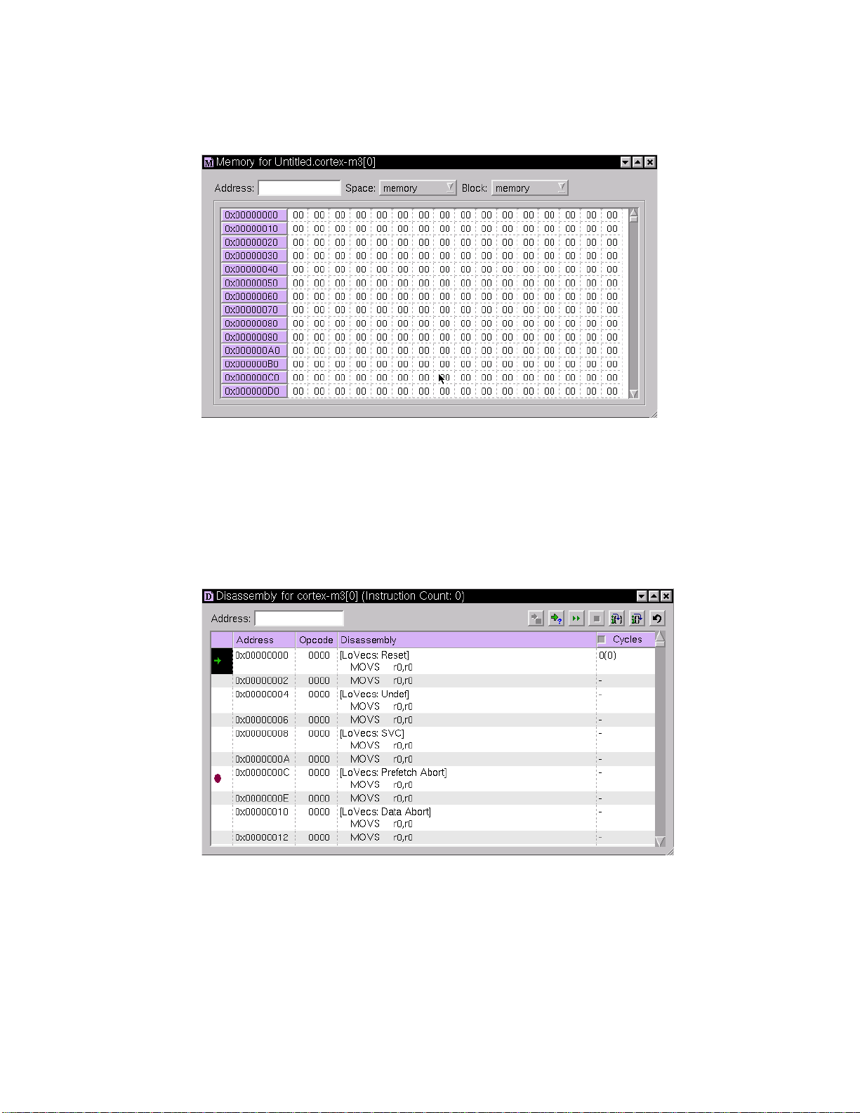
1.5.3 Memory Information
Figure 1-4 shows a Memory view of a Cortex-M3 model.
Figure 1-4 Cortex-M3 Memory View
1.5.4 Disassembly View
Figure 1-5 shows the disassembly view of a program running on the Cortex-M3 model in
SoC Designer Simulator. To display the disassembly view in the SoC Designer Simulator,
right-click on the Cortex-M3 model and select View Disassembly… from the context
menu.
Figure 1-5 Cortex-M3 Disassembly Window
All CADI windows support breakpoints – when double-clicking on the proper location a
red dot will indicate that a breakpoint is currently active. To remove the breakpoints simply double-click on the same location again.
Carbon Design Systems, Inc. Confidential
Page 31
Available Profiling Data 1-21
1.6 Available Profiling Data
Profiling data is enabled, and can be viewed using the Profiling Manager, which is accessible via the Debug menu in the SoC Designer Simulator. Both hardware and software
based profiling is available.
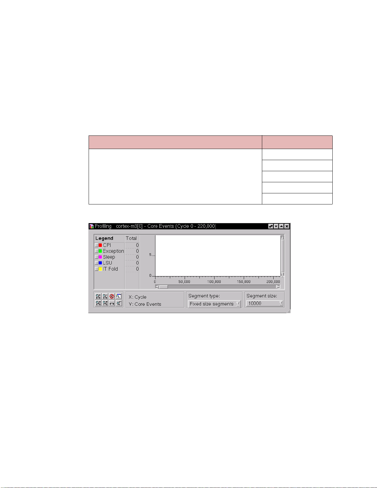
1.6.1 Hardware Profiling
Hardware profiling includes just the Core Events stream. The buckets supported by this
stream are shown in Table 1-10.
Table 1-10 Cortex-M3 Profiling Events
Stream Buckets
Core Events CPI
Exception
Sleep
LSU
IT Fold
An example of debug information for the Core Events stream is shown below.
Figure 1-6 Software Stream Debug Information
1.6.2 Software Profiling
Software-based profiling is provided by SoC Designer Plus. Profiling information is available in the SoC Designer Profiler. See the user guide for SoC or SoC Designer Profiler for
more information.
Carbon Design Systems, Inc. Confidential
Page 32

1-22 Using the Model Kit Component in SoC Designer Plus
Carbon Design Systems, Inc. Confidential
Page 33

Third Party Software Acknowledgement
Carbon acknowledges and thanks the respective owners for the following software that is
used by our product:
• ELF (Executable and Linking Format) Tool Chain Product
Copyright (c) 2006, 2008-2012 Joseph Koshy
All rights reserved.
Redistribution and use in source and binary forms, with or without modification, are permitted provided that the following conditions are met:
1. Redistributions of source code must retain the above copyright notice, this list of conditions and the following disclaimer.
2. Redistributions in binary form must reproduce the above copyright notice, this list of
conditions and the following disclaimer in the documentation and/or other materials
provided with the distribution.
THIS SOFTWARE IS PROVIDED BY THE AUTHOR AND CONTRIBUTORS ``AS
IS'' AND ANY EXPRESS OR IMPLIED WARRANTIES, INCLUDING, BUT NOT
LIMITED TO, THE IMPLIED WARRANTIES OF MERCHANTABILITY AND FITNESS FOR A PARTICULAR PURPOSE ARE DISCLAIMED. IN NO EVENT SHALL
THE AUTHOR OR CONTRIBUTORS BE LIABLE FOR ANY DIRECT, INDIRECT,
INCIDENTAL, SPECIAL, EXEMPLARY, OR CONSEQUENTIAL DAMAGES
(INCLUDING, BUT NOT LIMITED TO, PROCUREMENT OF SUBSTITUTE GOODS
OR SERVICES; LOSS OF USE, DATA, OR PROFITS; OR BUSINESS INTERRUPTION) HOWEVER CAUSED AND ON ANY THEORY OF LIABILITY, WHETHER IN
CONTRACT, STRICT LIABILITY, OR TORT (INCLUDING NEGLIGENCE OR OTHERWISE) ARISING IN ANY WAY OUT OF THE USE OF THIS SOFTWARE, EVEN
IF ADVISED OF THE POSSIBILITY OF SUCH DAMAGE.
Page 34

Carbon Design Systems, Inc. Confidential
 Loading...