

Page 1
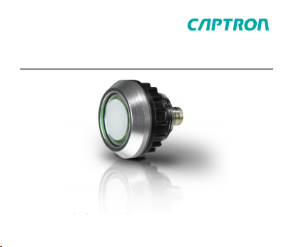
CHT1
CHT1
Original Operating Instructions
Original Operating Instructions
CHT1-1 / CHT1-5
CHT1-1 / CHT1-5
Page 2

This manual has been written for technicians/installers and operators
and should be kept for future reference. Read these operating
instructions carefully and make sure that you have fully understood
the contents before installing or working with the CHT1.
TIP
Metric and imperial measurements are used in drawings.
Imperial measurements are marked with [ ].
Safety
General safety
All work on electrical systems or operating equipment may only
be carried out by a specially qualified electrician according to the
applicable electrotechnical regulations.
The safety of the system in which the SENSORswitch is integrated is
the responsibility of the operator.
Page 3
Notes and symbols used
Warning notes in relation to personal injury / material damage are
formulated according to the "SAFE” principle. This means they
contain information on the type and source of the hazard, potential
consequences as well as how to avoid and avert danger. The
following hazard classifications apply in the safety notes:
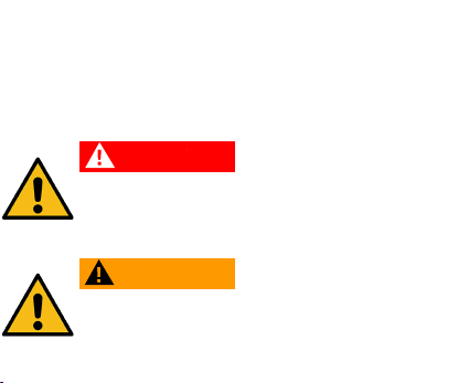
DANGER
Danger designates a hazardous situation, which, if
ignored, will lead to death or serious injury. The symbol
next to the warning indicates the type and source of the
danger.
WARNING
Warning designates a hazardous situation, which, if
ignored, may lead to death or serious injury. The symbol
next to the warning indicates the type and source of the
danger.
Page 4
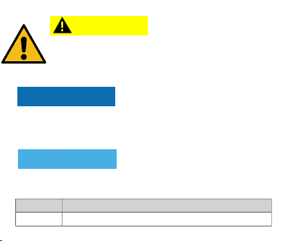
CAUTION
Caution designates a hazardous situation, which, if
ignored, may lead to injury. The symbol next to the
warning indicates the type and source of the danger.
NOTICE
Notice designates a situation, which may cause material
damages and impair the product’s function if attention is not
paid.
TIP
Tip provides additional useful information about the handling of
the product.
Symbol Meaning
4
Avoiding and adverting danger in the warning note
Page 5
Symbol Meaning
►
Instructions for action
All instructions to be followed within a procedure are
■
always listed in chronological order.
List
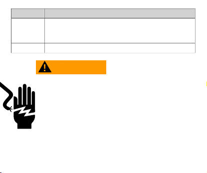
WARNING
Improper work on electrical systems!
Electric shock can result in death or life-threatening
injuries.
4
Before working on electrical systems, disconnect
them from their voltage supply and secure them
against being switched on again.
4
Work on electrical installations should be carried
out only by qualified personnel in compliance
with local and national electrical regulations and
specifications.
Page 6

Personnel qualifications
A qualified electrician is a person with suitable technical training,
expertise and experience as well as knowledge of relevant
standards, who can evaluate the work assigned to them
correspondingly and recognize potential risks.
Intended use
The SENSORswitch is intended for use in accordance with the items
listed here, the values from the “Technical specifications” chapter and
the product description.
■
Only connect the product to a limited energy source as per IEC
61010 or an NEC class 2 power supply unit.
■
Source current < 4 A at maximum operating voltage.
Reasonably foreseeable misuse
The switch is not suitable for:
Page 7
•
use as a safety component in accordance with Machinery
Directive 2006/42/EC.
•
use outdoors.
•
use in potentially explosive atmospheres.
Technical specifications
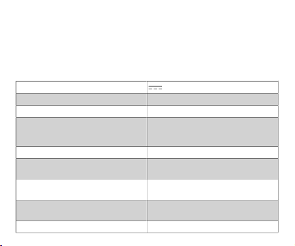
Operating voltage 10…30 V
Load current max. 400 mA
Output PNP-NO
Output pulse
optionally dynamic
CHT12
Reverse polarity protection Protection of all cables/lines
Short circuit protection Protected against short circuit and
Voltage drop
optionally dynamic
Power consumption Max. 20 mA at 24 V / Max. 20 mA at 24
Operating temperature -30...+70°C
Constant signal when actuated
approx. 300 ms
Toggle flip flop
overload
Max. 2 V at 400 mA
Max. 2 V at 200 mA
V
Page 8

Degree of protection IP Front IP69K
Type of actuation Capacitive
Actuation force No actuation force required
max. altitude 2000 m above sea level with "CSA
Relative air humidity Max. 95%, non-condensing
listing"
Connections
CHT1-_7_...
200 mm single strands with wire end ferrules
Wire end ferrules with plastic collars DIN 46228
Wire cross-section strands 0.15 mm
2
Page 9
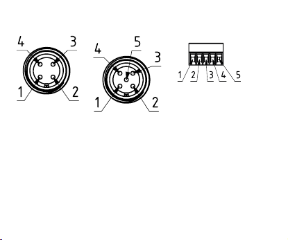
CHT1-_9_...
Plug M12, 4-pin
CHT1-_9_...
Plug M12, 5-pin
CHT1-_K_...
Terminal strip, 5-pin
CHT1-_5_...
Plug M8, 3-pin
CHT1-_5_...
Plug M8, 4-pin
CHT1-_5_...
Plug M8, 5-pin
Page 10
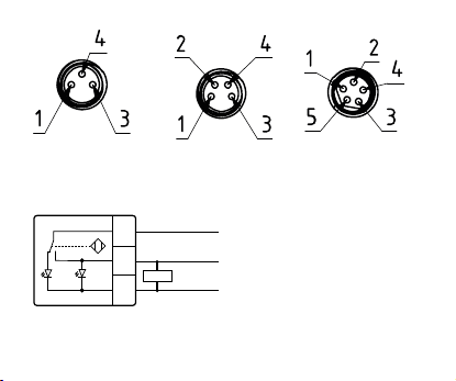
Connection plan
PNP-NO
+VDC
0V
3
4
1
brown
blue
black
LED1
LED2
Load
PNP-NO, 3-pin
Page 11
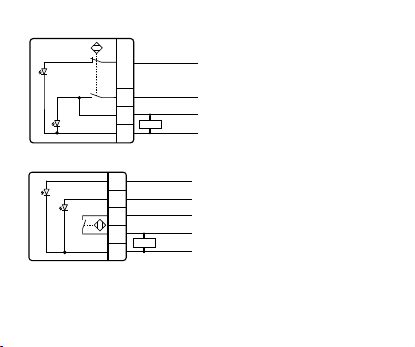
PNP-NO, 4-pin
3
4
2
1
+VDC / LED1
+VDC
0V
PNP-NO
white
brown
black
LED1
LED2
blue
Load
LED1
LED2
+VDC / LED2
+VDC / LED1
PNP-NO
0V
+VDC
3
4
5
1
2
white
grey
brown
black
blue
Load
PNP-NO, 5-pin
Dimensional drawing
Example representation plug, M8 4-pin
Page 12
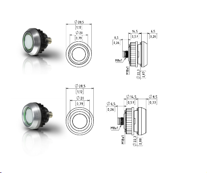
All dimensions in mm
CHT1-1_9
CHT1-5_9
Page 13
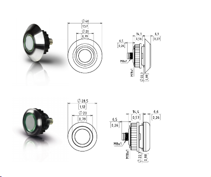
CHT1-1_8
CHT1-1_8/CPM20
Page 14
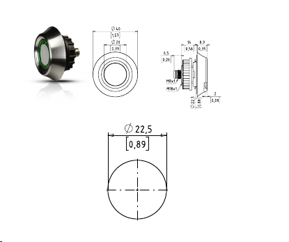
CHT1-6_8
Drilling pattern
Page 15
General description
The supplied switch can have options that differ from those shown in
this manual. This does not affect the function. The CHT1 is equipped
with two different colored LEDs. The LEDs are actuated differently
depending on the pin configuration.
Assembly
Requirements: Mounting surface is level and
clean.
► Disconnect the system from its voltage
supply and secure it against being
switched on again.
► Set the desired position of the
SENSORswitch and drill the hole
according to the drilling pattern.
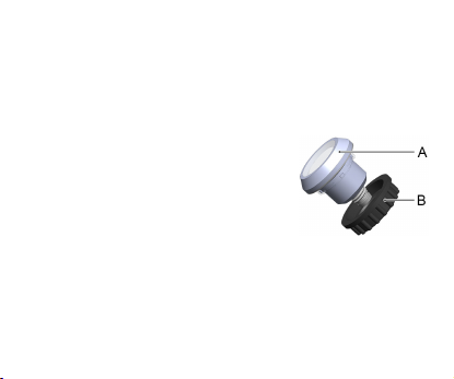
► Unscrew the lock nuts (B) from the
SENSORswitch (A).
► Insert the SENSORswitch into the
prepared hole and screw the lock nuts
(B) back on.
Page 16

► Position the SENSORSwitch (A) and
tighten the lock nuts with max. 1 Nm.
► Connect the SENSORswitch (A)
electrically according to the connection
plan.
Maintenance
Carry out the following maintenance operations at the specified
intervals.
Operation as needed annually
Clean the switch surface X
Check cable for integrity
Check screw connection for
tightness
X
X
Page 17

NOTICE
Solvents contained in cleaning agents can attack the plastic
of the button!
4
Clean the surface of the button with a neutral cleaning agent
or a damp microfiber cloth.
Disassembly
► Disconnect the system from its voltage supply and secure it
against being switched on again.
► Disconnect the electrical connection and remove the lock nuts.
Disposal
Different types of electrical and electronic components must be
recycled according to their type. All applicable statutory, state and
local laws and regulations must be complied with.
Page 18

Manual updates
CAPTRON reserves the right to make changes to the contents of this
manual as needed. The most current version can be found on our
website www.captron.com .
Imprint
The operating instructions have been authored and published by
CAPTRON Electronic GmbH
Johann-G.-Gutenberg-Straße 7
82140 Olching – Germany
Tel.: +49 (0)8142 - 44 88 - 160
www.captron.com
Copyright 2020
CHT1 ohne Relais 1.4
Page 19

Product description
 Loading...