

Page 1
TECHNICAL MANUAL
FOR
INSTALLATION, OPERATION
Effective Date: 11-04
AND MAINTENANCE
OF
THE CAPTIVE-AIRE
MODEL "C-ESP" SERIES
POLLUTION CONTROL UNITS
WITH CGPC-6000-ESP COMMAND CENTER
W ARNING
Improper installation, adjustment, alteration service or maintenance can cause property damage, injury or death. Read
the installation, operation and maintenance instructions thoroughly before installing or servicing this equipment. Only
trained and qualified service personnel should install or service this equipment.
CAPTIVE-AIRE SYSTEMS, INC.CAPTIVE-AIRE SYSTEMS, INC.
CAPTIVE-AIRE SYSTEMS, INC.
CAPTIVE-AIRE SYSTEMS, INC.CAPTIVE-AIRE SYSTEMS, INC.
360 NORTHBROOK DRIVE • YOUNGSVILLE, NC 27596 USA
PHONE: 919-554-2414 • TOLL FREE: 866-784-6900 • FAX: 919-554-9374
email:webhome@captiveaire.com • www.captiveaire.com
Page 2

TECHNICAL MANUAL
FOR
INSTALLATION, OPERATION
AND MAINTENANCE
OF
THE CAPTIVE-AIRE
MODEL “C-ESP” SERIES
POLLUTION CONTROL UNITS
WITH CGPC-6000-ESP COMMAND CENTER
Published by:
CAPTIVE-AIRE SYSTEMS, INC.
Y oungsville, North Carolina 27596
U.S.A.
First Printing: November , 2004
© Copyright 2004, Captive-Aire Systems, Inc.
ALL RIGHTS RESERVED. NO PART OF THIS BOOK MAY BE REPRODUCED, STORED IN A RETRIEVAL SYSTEM, OR TRANSMITTED IN ANY
FORM BY AN ELECTRONIC, MECHANICAL, PHOTOCOPYING, RECORDING MEANS OR OTHERWISE WITHOUT THE WRITTEN PERMISSION
OF CAPTIVE-AIRE SYSTEMS, INC. COPYRIGHT 2004.
The manufacturer reserves the right to modify the materials and specifications resulting from a continuing
program of product improvement or the availability of new materials.
The Captive-Aire C-ESP Unit is designed and engineered by
CAPTIVE-AIRE SYSTEMS, INC.
360 Northbrook Drive, Y oungsville, NC 27596.
Page 3

TABLE OF CONTENTS
INTRODUCTION.....................................................................................................5
SPECIFICATIONS ............................................................................................... 6-7
MODEL NUMBER EXPLANA TION ..........................................................................8
TYPICAL INST ALLA TION.........................................................................................9
SAMPLE C-ESP CONFIGURATIONS ..............................................................10-11
RECEIVING & INST ALLA TION ..............................................................................12
EQUIPMENT LIFTING PROCEDURE...................................................................13
ASSEMBLING C-ESP HOUSING ON UNITS SPLIT FOR SHIPMENT............ 14-15
SMOKE CONTROL .............................................................................................. 16
C-ESP FIRE MODE........................................................................................ 17-18
DAIL Y OPERA TION......................................................................................... 19-20
COMMAND CENTER INSTRUCTIONS .......................................................... 21-24
TIME CLOCK OPERA TION ..................................................................................25
DETERGENT PUMP OPERATION................................................................. 26-27
PREVENTIVE MAINTENANCE........................................................................ 28-29
CELL CONFIGURA TION.......................................................................................30
SPARE CELLS...................................................................................................... 31
TROUBLE-SHOOTING – ESP SECTION....................................................... 32-33
ODOR CONTROL .......................................................................................... 34-37
EXHAUST F AN SECTION ............................................................................... 38-39
RP DEVICE INITIAL ST ART UP ............................................................................40
TROUBLE-SHOOTING – GENERAL.............................................................. 41-44
DETERGENT PUMP PARTS................................................................................45
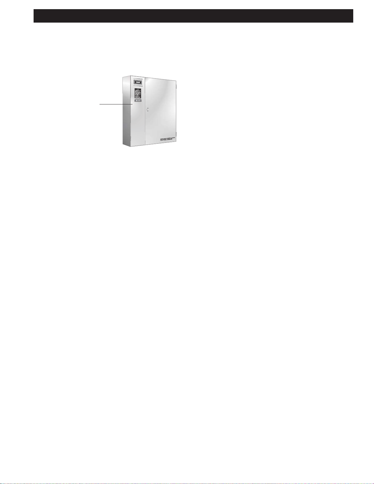
CONTROL CABINET ............................................................................................46
SUB P ANEL ..........................................................................................................47
NAMEPLA TE DA TA ......................................................................................... 48-49
TERMINAL VOL T AGES ................................................................................... 50-51
WIRING DIAGRAM ................................................................................................52
OPTIONAL CONNECTION INSTRUCTIONS......................................................... 53
PLC ST A TUS LIGHTS ............................................................................................ 54
DRAIN .................................................................................................................... 55
SPRAY ODOR WIRING ......................................................................................... 56
SPRA Y ODOR TERMINAL VOL T AGES ................................................................. 57
CGPC-6000-ESP SERIES CONTROL............................................................. 58,60
CGPC-6000-ESP COMPONENT SCHEDULE................................................. 59,61
POWER PACK PARTS.......................................................................................... 62
CELL PARTS ......................................................................................................... 63
MISCELLANEOUS P ARTS .................................................................................... 64
STARTUP INSTRUCTIONS ................................................................................... 65
INSPECTION REPORT ......................................................................................... 66
WARRANTY ..................................................................................Inside back cover
4
Page 4

INTRODUCTION
ir quality is a major concern in many large
A
cities world wide, particularly in America. As a result,
many commercial kitchens will require pollution control equipment in their exhaust systems to comply with the increasing
demands of environmental control agencies. In addition, pollution control equipment is being used for other reasons such as
kitchens in high-rise buildings to allow the exhaust to discharge
out the side of the structure saving the cost of running the duct
up many floors to the roof.
Smoke pollution control, in kitchen exhaust systems, has
typically been accomplished by any one of the following methods: gas fired incinerators, scrubbers, filtration units or electrostatic precipitators (C-ESP). Incinerators literally burn the
pollutants and, while effective, can be very costly and hazardous to operate. Scrubbers consist of a water bath and
extraction baffles to remove the pollutants and, though quite
effective on grease removal, they typically require the addition of high efficiency filters to abate smoke below control
agencies’ standards. Filtration units use a series of impingement filters to remove the pollutants and done properly can
be quite effective on both smoke and grease.
The Captive-Aire pollution control unit, model C-ESP , can be
manufactured with either electrostatic precipitation (C-ESP)
or Filtration (C-TPF). Captive-Aire has manufactured commercial kitchen exhaust systems since the early 1980's. When
initial cost is a greater concern the C-TPF unit is a sound
alternative.
The C-ESP unit is available in several configurations, as illustrated on the following pages, ranging in capacity from 1000
to 32,000 CFM (472 to 15,102 L/s). Most models can include
an optional exhaust fan and odor abatement equipment.
Basic Facts About Smoke
Smoke particles are extremely small and not visible to the
human eye unless thousands of them are grouped together
to form what we see as smoke. Individual particles are measured in units called microns and one micron equals 1/25,400
of an inch (1/64,516 of a cm).
Smoke generated by commercial cooking equipment has a
particulate size of between 0.3 and 0.8 microns and it is these
very small particles that smoke abatement equipment must
remove from the air stream. The amount of smoke being discharged from a kitchen exhaust duct is measured in terms of
its density , referred to as opacity - the degree to which emissions block light. A 100% opacity level would be solid black
and 0% would be perfectly clear. Control agencies that have
adopted smoke pollution ordinances are requiring an opacity
level of no more than 20%, which is a very light blue smoke.
Typically , heavy smoke producing cooking such as charbroiling, creates an opacity level of 60% to 70%. Opacity readings are taken by the human eye by viewing the smoke being
discharged and then assigning a percentage of opacity to
what is seen. Though this method is quite subjective, it is
the method practiced by control agency inspectors who are
trained and certified in determining opacity percentages. Other
more technical methods of determining opacity or particulate
density are achieved through the use of opacity meters and
cascade impactors. This level of analysis is usually referred
to as source testing. Control agencies occasionally require
this type of analysis and if so, the testing is conducted by
state certified contractors which can be quite costly and timeconsuming. The efficiency of a C-TPF is based on how well it
reduces the opacity level of a given airstream.The CaptiveAire unit will reduce the opacity level below 20%, thereby
meeting the requirements of environmental control agencies.
Basic Facts About Odor
Cooking odors (molecules) generated by the combustion of
animal and vegetable matter result in an extremely complex
mixture of reactive organic gases (ROG’s). A small percentage
of these odors may be absorbed by the grease particles but the
vast majority exist separately in the airstream. The ROG molecules are much too small to be removed by any type of filter and
therefore, other methods must be used. There are several methods with which to manage the odor. One method is to use a
media bed. The two most popular types of media bed are activated charcoal, which absorbs and retains the odor molecules,
and the use of an odor-oxidant media (potassium permanganate) which oxidizes the molecules to solids and then retains
them. The other method involves the use of a liquid delivered with
a finely atomized spray . This spray performs a similar function to
potassium permanganate in that it adsorbs or chemically neutralizes odors. This process has the benefit of the end user being
able to adjust the amount of spray and thus the effectiveness and
cost of the odor control.
The life of the media bed type of odor control is dependent
upon several factors such as how much media is used, type
of odor, amount of odor molecules, grease loading and air
temperature. Typically, any of the above mentioned types of
media can remove 85% - 90% of the molecules. Determining
the efficiency of odor control can be very subjective, as testing
is usually conducted by the human nose. More scientific testing is available through ROG analysis, but this involves considerable costs.
Grease Removal - The Important First Step
Grease particles are also measured in terms of microns and
grease generated by commercial cooking equipment has a
particulate size of 10 microns and up. Pollution control equipment is not limited to removing smoke particles, but will also
remove a majority of the grease particles remaining in the
airstream. Therefore, the grease extraction efficiency of the
exhaust hood plays an important role in the operation and
performance of pollution control equipment.
Removal of grease particles before they reach smoke and
odor control equipment will significantly increase the smoke
abatement efficiency and the life of the odor abatement media. It is highly recommended that a Captive-Aire Ventilator be
used with the unit as it has a grease extraction efficiency of
95%. Other high efficiency exhaust hoods and standard filter
type hoods may be used with the unit. Contact Captive-Aire
Systems for details.
5
Page 5

SPECIFICATIONS
General
Furnish one (1) Captive-Aire Pollution Control Unit model number C-ESP series as manufactured by Captive-Aire Systems,
Inc. of Youngsville, North Carolina in accordance with the
following:
The pollution control unit shall consist of a smoke control section, odor control section (optional) and an exhaust fan section
(optional) all built on a common base as an integral unit. Smoke
control shall be accomplished by electrostatic precipitation
(ESP). The unit shall be ETL listed and labelled.
Smoke Control Section
The smoke control section shall contain one or more electrostatic precipitator (ESP) cells to remove smoke particles
from the air stream to a level no higher than 20% opacity
when operated in accordance with the operation and maintenance guidelines. The ESP cells shall be of a floating plate
design to eliminate plate warpage during high heat operation. The cells shall be positioned on slide tracks so that
they may be easily removed through a hinged cell access
door(s). For ease of handling, individual cells shall weigh
less than 54 lbs. There shall be removable, cleanable debris
screens located immediately upstream of the ESP cells and
a moisture separator immediately downstream. An electrical panel mounted on the unit shall contain the high voltage
power pack assembly , safety disconnect switch, main disconnect switch, fuses and a magnetic starter for the exhaust fan when fan is included. The safety disconnect switch
shall interface with the electrical panel access door such
that when opened it will shut off service to the power pack(s)
and ground them to drain the residual electrical charge from
both the power pack(s) and ESP cells. The ESP cell access door shall interface with the electrical panel access
door so that it cannot be opened without first opening the
electrical panel access door . The high voltage power pack(s)
shall be self-limiting type and shall be self contained. The
electrical panel shall include indicating lights to monitor cell
and transformer voltage. The main disconnect switch for the
exhaust fan and control circuits shall lock the electrical panel
access door closed when in the “on” position. The unit shall
contain one or more wash manifold(s) with brass spray
nozzles to wash the ESP cells with hot detergent injected
water each time the exhaust fan is shut off.
Fire Detection
A thermost at, set at 250o F, shall also be located in the filter
section to shut down the exhaust fan in the event of a fire.
Optional Fire Damper for use in Canada
The unit shall include a UL listed fire damper , with a 280o F
fusible link, located downstream of the filters to prevent passage of fire to the duct downstream of the unit
Odor Control Options
Media bed of 50/50 Blend Potassium Permanganate
and Carbon Blend
The unit shall be provided with odor control utilizing a media
bed of 50% potassium permanganate 50% carbon blend. The
odor removal media shall be housed in slide out reusable steel
modules. There shall be a 30% pleated media after filter lo-
cated immediately downstream of the odor control media. Replaceable filters shall be mounted in filter slide tracks to prevent
air bypass around the ends of the installed filter bank. The odor
control media and after filters shall be removable through side
access doors with lift and turn latches.
Spray Odor Control
The unit shall be provided with a spray odor control system
utilizing an odor neutralizer chemical. The odor spray control
cabinet shall be mounted on the side of the unit and shall
contain a liquid spray compressor piped to the spray nozzle
in the fan plenum, adjustable delay timers with fuse protected circuitry factory wired to the unit electrical panel. The
cabinet shall include one 5 gallon container of Formula GS710 Odor Neutralizer. The cabinet shall contain a heater to
prevent freezing of the odor neutralizer.
Exhaust Fan Options
Exhaust Fan (Standard Centrifugal Fan)
The unit shall include a centrifugal exhaust fan. The exhaust
fan shall be an upblast arrangement with a non-overloading
wheel. The motor, drives, bearings and fan mounting base
shall be located out of the exhaust air stream as required by
the IMC (International Mechanical Code) and NFP A-96. The
fan shall be ETL Listed and shall be AMCA certified and bear
the AMCA seal for performance. The fan housing shall be constructed of heavy gauge steel. The fan bearings shall be heavy
duty pillow block type rigidly mounted on heavy structural steel
supports. The motor shall be ODP. The fan shall include a
disconnect switch.
Exhaust Fan (Optional Tubular Fan)
The unit shall include a tubular centrifugal exhaust fan. The
exhaust fan shall be an arrangement #10 with a non-overloading BI, AF wheel. The motor, drives, bearings and fan mounting
base shall be located out of the exhaust air stream as required
by the IMC (International Mechanical Code) and NFPA-96. The
fan shall be AMCA certified and bear the AMCA seal for performance. The fan housing shall be constructed of heavy gauge
steel. The fan bearings shall be heavy duty rigidly mounted on
heavy structural steel supports. The motor shall be ODP three
phase mounted on a common base with the fan and shall be
pre-wired to the electrical cabinet located on the unit. The electrical cabinet shall include a disconnect switch, motor starter ,
overloads and fuses. The factory provided drive assembly shall
be adjustable pitch on 5 HP and smaller and fixed pitch on 7.5
HP and larger . It shall also be sized for a minimum 1.5 service
factor. After final system balancing, fixed pitch sheaves shall be
provided and installed by the air balancing contractor to provide
proper flow at actual installed conditions.
Unit Construction
The unit housing shall be constructed of a minimum of 16
gauge G90 bright galvanized steel. The perimeter base shall
be 12 gauge formed channel with lifting lugs at each corner
and along the length as required. The internal housing shall
be externally welded liquid tight for compliance to the International Mechanical Code and NFPA-96 grease duct construction requirements.
6
Page 6
SPECIFICATIONS
Fire Extinguishing System Options
Specifier Note: NFP A-96 requires a fire extinguishing system for protection of the smoke and odor control sections
and protection of the duct down stream of any filters or dampers. Not all authorities having jurisdiction require protection.
Check with your AHJ. If required, specify one of the following systems.
Wet chemical system
Provide a complete factory mounted Ansul wet chemical fire
extinguishing system, including nozzles piping and detection runs. Pipe penetrating the unit cabinet shall use a UL
listed fitting. System shall be installed in accordance with
the systems listing and NFP A-96. The Ansul Automan cabinet shall be mounted on the side of the unit for easy access,
certification and service.
Water spray sprinkler fire system
Specifier Note: Units that are located indoors may be factory
pre-piped for a wet pipe building sprinkler system.
Provide a pre-piped water spray fire system installed in accordance with NFP A-96. The unit shall be piped with one pendent type sprinkler nozzle located in the smoke control section, one in the odor control section, if equipped with 50/50
media bed, and one in the exhaust fan section for interconnection to the building sprinkler system by the appropriate
trades. Pipe penetrating the unit cabinet shall use a UL listed
fitting. Nozzles shall be the bulb type rated at 325o F.
Check Out and Demonstration
Upon completion of installation, the entire pollution control
system, including the kitchen exhaust hoods, shall be commissioned by factory certified personnel. Start-up shall include checking all filters, filter monitoring station, odor control and exhaust fan. The appropriate maintenance personnel shall be given a technical manual and a complete demonstration of the system, including operation and maintenance procedures. Upon completion of the commissioning,
a detailed start-up report shall be made available to the architect and owner certifying proper system operation. Changes
required in fan drive components shall be performed by the air
balancing contractor under the direction of the factory certified person(s) performing the start-up.
ELECTROSTA TIC CELL
ISOMETRIC VIEW SIDE VIEW
7
Page 7
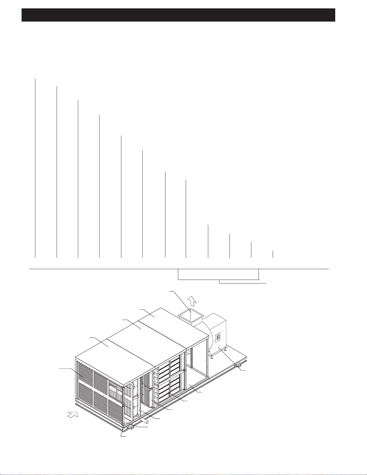
MODEL NUMBER EXPLANATION
The assigned model number of a C-ESP unit will indicate the number of Cell Banks and if it has spray odor control, single or
double pass odor control, if it has an exhaust fan plus other data. The following example shows the make-up of a model number .
The model number of your C-ESP unit along with other data can be found on the nameplate which is attached to the
electrical control panel on the unit. Refer to page 49.
Standard Prefix Series of C-ESP System (Remote Smoke Pollution Control)
1 ESP = Single Pass Electrostatic Cells
2 ESP = Double Pass Electrostatic Cells
ESP Cell Configuration (WxH) - 1x1, 2x1, 3x1, 2x2, 3x2, 4x2, 3x3, 4x3, 3x4, 4x4
Nominal FPM ESP Cell V elocity
250 FPM = Heavy and Extra Heavy Duty Cooking,
500 FPM = Light and Medium Duty Cooking
Number of Wash Banks
DW = Double Wash, Blank = Single Wash
Odor Control Option
SO = Single Pass Odor Control
DO = Double Pass Odor Control
SPO =Spray Odor
T otal CFM
Exhaust Fan Option
EFS = Exhaust Fan, unhoused, spring isolated
EFN = Exhaust Fan, unhoused, not spring isolated
EFHS = Exhaust Fan, housed, spring isolated
EFHN = Exhaust Fan, housed, not spring isolated
(BLANK) = No Exhaust Fan
Fan Type - C = Centrifual, T = Tubular
Fan Size
Fan Motor H.P .
Hand - R = Right Hand
L = Left Hand
C 1ESP - 3x2 - 500 - DW - DO - 9000 - EFN - C - 300 - 5 - R
Block 1 2 3 4 5 6 7 8 9 10 11
All Blank, if no exhaust fan
Exhaust Fan Section (EFN)
Plenum Section
Optional Spray Odor (SPO)
Odor Control (optional)
Section (SO, DO)
ESP section
ESP Cell
Configuration
(3 x 2)
Inlet Airflow
Plenum Access
Odor Media (DO shown)
Moisture Separator
ESP Cells Single Pass (1ESP)
Debris Screen
Hand (Right Hand Access)
Access Side, R or L, Determined by Facing
Unit with Inlet Airflow to back of head
Fan Type (Centrifual
or Tubular)
8
Page 8
TYPICAL INSTALLATION
9
Page 9
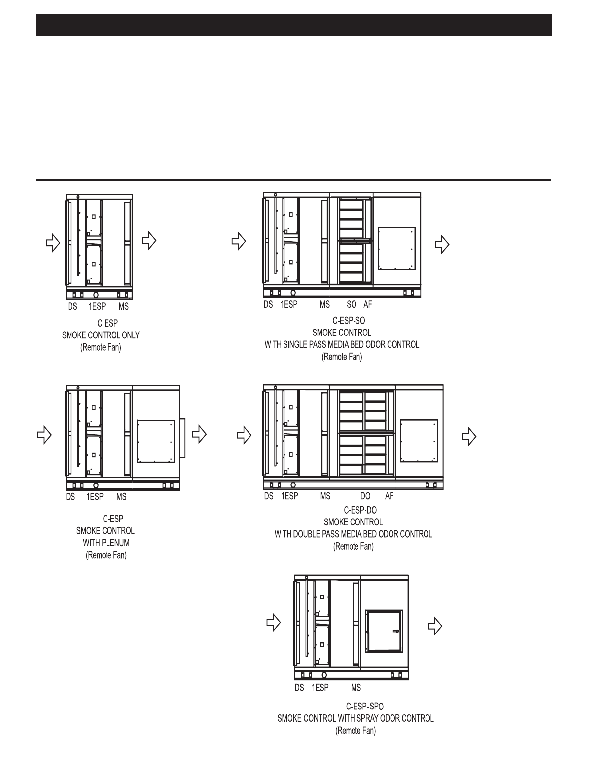
SAMPLE C-ESP CONFIGURATIONS
The Captive-Aire unit is available in sizes ranging in capacity
from 1000 to 32,000 CFM (472 to 15,102 L/s). Each unit is
equipped with Three Phase Filters for smoke control, and
may include an exhaust fan, odor abatement equipment and
Quencher System, or Ansul System as an option. The following illustrations are examples of the most common configurations.
KEY
1ESP = Single Pass Electro-
static Cells
2ESP = Double Pass Electro-
static Cells
AF = 30% After Filter
D O = Double Pass Odor
Kor48/Carbon blend
DS = Debris Screen
EFS = Exhaust Fan, unhoused,
spring isolated
EFN = Exhaust Fan, unhoused,
not spring isolated
EFHS = Exhaust Fan, housed,
spring isolated
EFHN = Exhaust Fan, housed, not
spring isolated
FD = Optional Curtain Fire
Damper
MS = Moisture Separator
S O = Single Pass Odor
Kor48/Carbon blend
SPO = Spray Odor Cabinet
10
Page 10
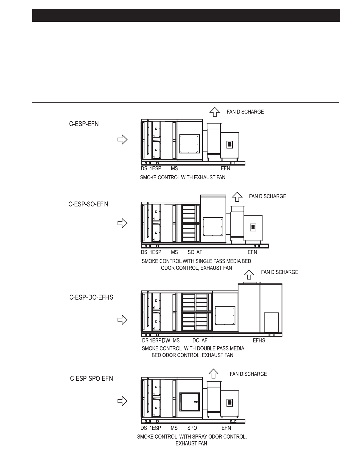
SAMPLE C-ESP CONFIGURATIONS
KEY
1ESP = Single Pass Electro-
static Cells
2ESP = Double Pass Electro-
static Cells
D O = Double Pass Odor
Kor48/Carbon blend
DS = Debris Screen
DW = Dual Wash (2nd wash
manifold)
EFS = Exhaust Fan, unhoused,
spring isolated
EFN = Exhaust Fan, unhoused,
not spring isolated
EFHS = Exhaust Fan, housed,
spring isolated
EFHN = Exhaust Fan, housed,
not spring isolated
FD = Optional Curtain Fire
Damper
MS = Moisture Separator
SO = Single Pass Odor
Kor48/Carbon blend
SPO = Spray Odor Cabinet
11
Page 11

RECEIVING & INSTALLATION
RECEIVING
Most C-ESP units are shipped in one piece. However , some
units, because of size or special jobsite conditions, may be
shipped in multiple sections. Follow the instructions
provided with the unit to join sections back together. If the
unit includes media bed odor control, the KOR48/carbon odor
control media is packaged separately . V erify against the shipping documents that you have received all items and note
any shipping damage, obvious or hidden, to your carrier and
on your Bill of Lading. If damage is found, immediately file a
claim with the transport company. All units are thoroughly
inspected and fully operation tested at the factory prior to
shipment.
Verify that the electrical and air flow ratings on the unit nameplate agrees with jobsite requirements. If a contradiction arises
notify the factory prior to proceeding with installation.
SAFETY CONSIDERA TIONS
Installing and servicing the C-ESP unit can be hazardous
due to the presence of electrical components. Only trained
and qualified service personnel should install or service this
equipment.
Untrained personnel can perform basic maintenance, such
as cleaning and replacing filters. All other operations should
be performed by trained service personnel. When installing
or servicing, observe precautions in literature and on tags
and labels attached to unit.
Follow all safety codes. Wear safety glasses and work gloves.
Use quenching cloth for brazing operations. Have fire extinguisher available. Read these instructions thoroughly .
WARNING
Before installing or servicing system, always turn off main
power to system. There may be more than one disconnect
switch. Electrical shock can cause personal injury or death.
RIGGING
All units are provided with a minimum of four (4) lifting points
for rigging attachment. WARNING: Use all lifting points provided. (Refer to Page 13) Spreader bars are mandatory to
prevent contact and damage to the unit by lifting hooks, straps,
cables, or chains. Consult the mechanical or structural engineer before moving the unit across the roof deck.
INSTALLA TION CODES
This unit requires external plumbing and electrical connections
to be made in the field. It is recommended that the Authority
Having Jurisdiction (AHJ) be consulted regarding local codes
and installation procedures. Captive-Aire Systems is not responsible for obtaining necessary approvals and permits which
may be required for installation, nor is it responsible for verifying
that the unit has been installed in accordance with national,
state, and local codes. In the absence of locally adopted codes
use the current editions of the National Electrical Code and the
Uniform Mechanical Code. Connections of the exhaust duct to
the inlet and outlet of the C-ESP unit must be fully welded to
comply with NFPA-96.
INST ALLATION PRECAUTIONS
1. The services of qualified contractors are essential for safe
and proper installation of this equipment.
2. The air volumes and external static pressures that are
listed on the unit are for the middle of the operating range of
the filters. The initial air volume should be at least 10% higher
than the listed CFM. As the filters load up the air volume will
drop. This is inherent to this type of unit. If the unit is set up
at or below the design CFM, as the filters load up, the kitchen
hood may experience smoke loss problems. Please consult the factory if you have questions.
3. The unit is designed for installation on a level surface.
4. When installed in an enclosed space a fire rated enclosure may be required for the unit and associated duct work.
Consult the Authority Having Jurisdiction.
5. Consult the Authority Having Jurisdiction regarding requirements covering the point of termination of the exhaust
outlet of this unit. Minimum distances must usually be
maintained between the exhaust outlet and any outside air
intakes and/or adjacent structures or property lines.
6. Do not apply power to the unit until all electrical connections have been made and a pre-start-up preliminary inspection has been completed.
7. Allow a minimum of 36 inches clearance in front of the
filter access door and electrical compartment door for service and routine maintenance per NEC.
SHORT TERM STORAGE
Units that include media bed odor control are provided with
KOR48/carbon media which is shipped separate from the
unit. KOR48/carbon media must be stored in a dry place
with less than 95% relative humidity .
EXHAUST FAN RECEIVING AND STORAGE
If the unit is equipped with an exhaust fan it must be relubricated as soon as it arrives. T o prevent corrosion all bearings should receive grease and be rotated the first of every
month. Rotate the wheel several revolutions every three to
five days to keep a coating of grease on all internal bearing
parts. Turn the wheel by hand while greasing bearings. A
clean 1/16" bead of grease must appear on each side of each
bearing. Refer to specific bearing lubricating instructions on
the fan. Also, refer to bearing lubricating instructions found in
the exhaust fan section of this manual.
Bearings which are to be stored or idle for an extended period of time should be wrapped in a neutral grease-proof paper, foil, or plastic film. Compounds can be recommended
by the bearing manufacturer to provide protection for several
months to several years.
After long-term storage, grease should be purged from the
bearings and fresh grease injected prior to start-up.
12
Page 12
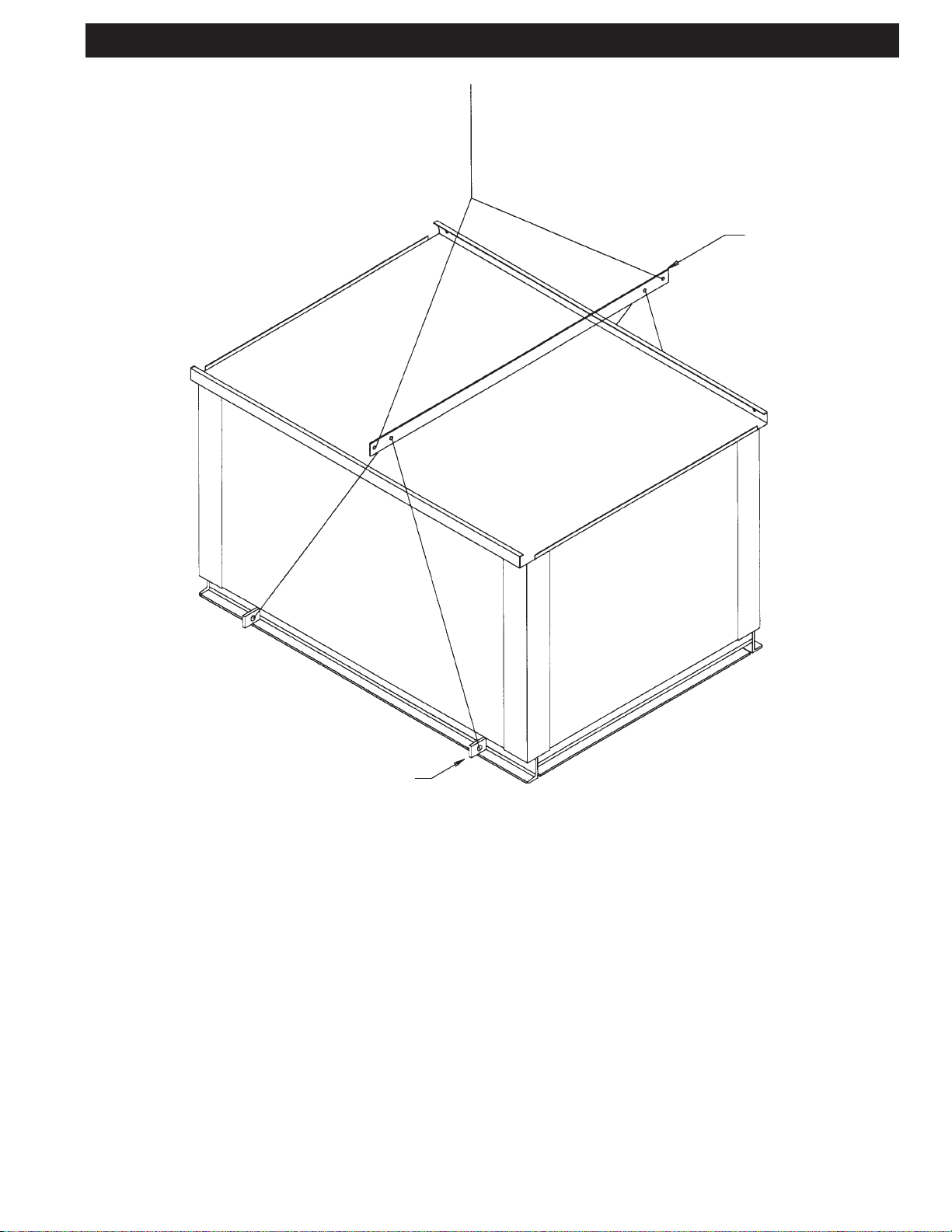
EQUIPMENT LIFTING PROCEDURE
SPREADER
BAR
LIFTING
LUGS
1 .All units are provided with a minimum of four lifting points for rigging attachment. All lifting
points must be used.
2 .Spreader bars are mandatory to prevent contact and damage to the unit by lifting hooks,
straps, cables or chains.
13
Page 13
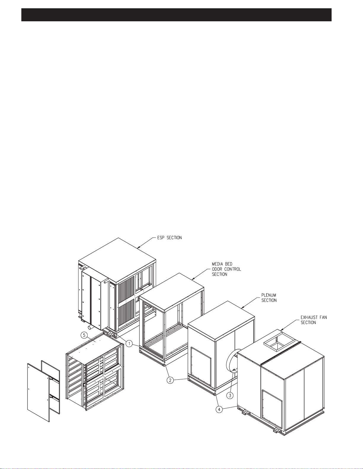
HOUSING ASSEMBLY INSTRUCTIONS
Typically, C-ESP units are shipped as one piece. Sometimes for building accessibilty reasons a unit may be shipped in
multiple pieces. If this is the case, refer to the instruction below and on page 15.
1. Attach "ESP Section" to "Media Bed Odor Control
Section":
Bolt "Media Bed Odor Control Section" and "ESP Section"
bases together on outside of unit, using 3/4" holes. Tek
screw walls and roofs together, using 3/16" holes. Continuously weld: floor, wall, and roof seams from inside of unit.
2. Attach "Media Bed Odor Control Section" to "Plenum Section":
Bolt "Media Bed Odor Control Section" and "Plenum Section" bases together on outside, using 3/4" holes. From
inside plenum, tek screw walls and roofs together, using
3/16" holes. Continuously weld: floor, wall, and roof seams
from inside of unit.
3. Attach Fan Inlet to "Plenum Section" outlet:
Push "Exhaust Fan Section" about 7 inches from "Plenum Section". T ek screw & caulk fan duradyne to plenum
interconnect ring, at 5 inch intervals (minimum). Duradyne
is pre-attached to fan inlet side.
4. Attach "Plenum Section" to "Exhaust Fan Section":
Bolt "Plenum Section" and "Exhaust Fan Section" bases
together on outside, using 3/4" holes. From inside of plenum, tek screw walls and roofs together, using 3/16" holes.
Continuously weld floor seam from inside plenum. "Exhaust Fan Section" walls and roof to remain removable for
exhaust fan replacement, tek screw and bolt only .
5. Assemble "Media Bed Odor Control Section":
Refer to "Media Bed Odor Control Section Assembly Instructions" drawing.
6. Reconnect Electrical to Exhaust Fan
14
Page 14
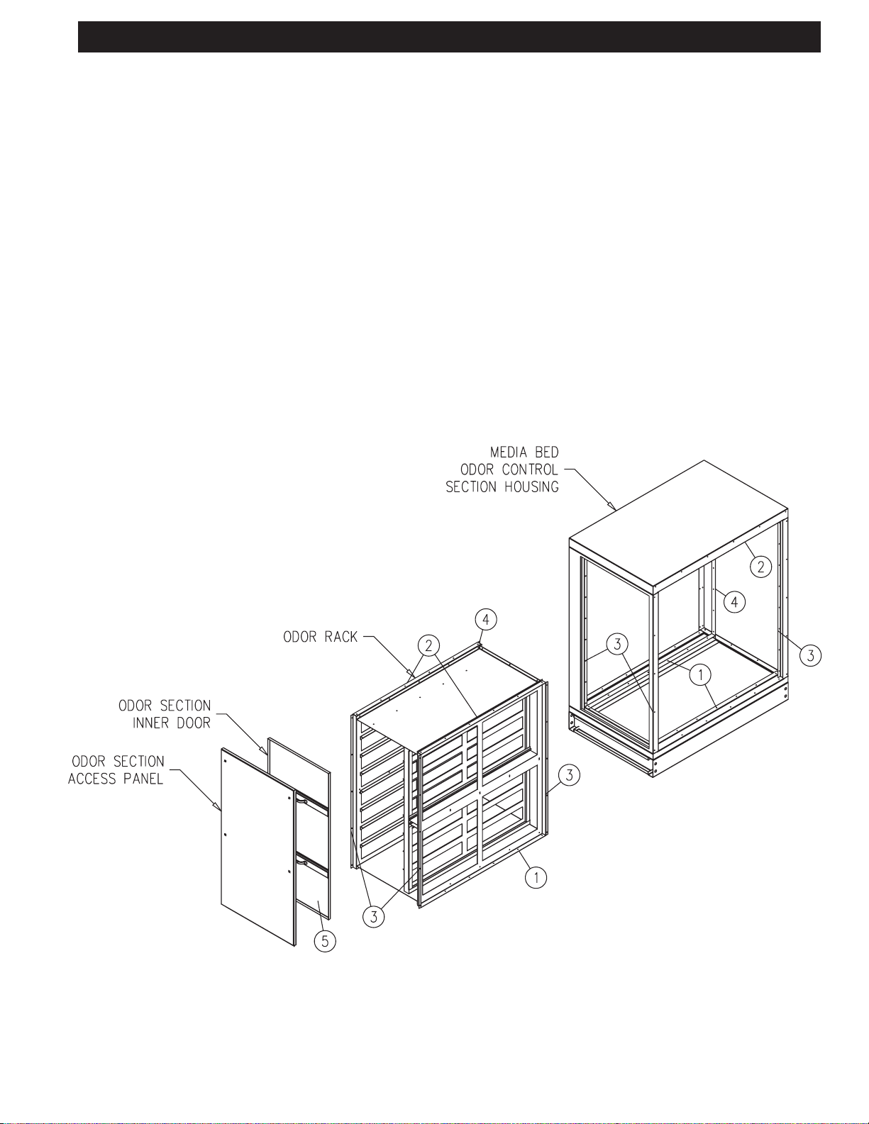
MEDIA BED ODOR CONTROL SECTION ASSEMBLY INSTRUCTIONS
NOTE: Assemble this section, only after the rest of
the unit has been assembled.
1.Slide odor rack into unit through door opening. T ek screw
rack to floor rails, using 3/16" holes.
2.T ek screw upper rack to both sides of roof rails.
3.Tek screw first 3 sides to mouning rails from outside of
the unit.
4.Attach fourth side by entering odor rack to reach screw
holes.
5.Attach odor section inner door , flip latches to secure.
15
Page 15
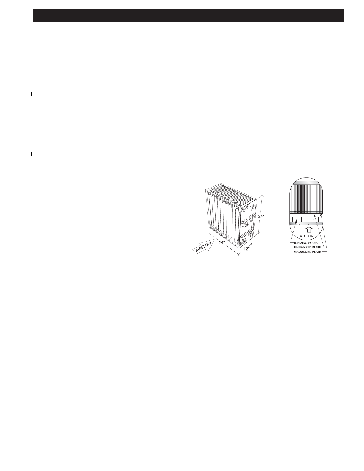
SMOKE CONTROL
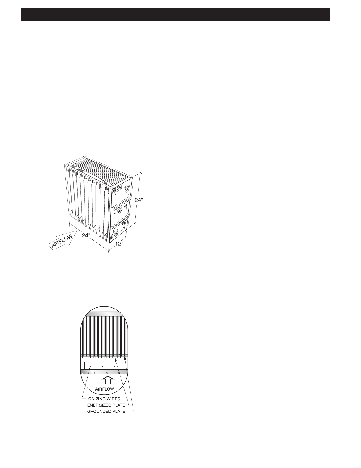
Principle of Operation
The Captive-Aire Pollution Control Unit removes smoke particles
by electrostatic precipitation. The principle of operation of electrostatic precipitation is actually quite basic. The electrostatic cell
is made up of a series of aluminum plates spaced approximately
1
/4” (6.35mm) apart and the number of cells used is determined
by the air volume and the type of cooking equipment involved.
Every other plate is energized with 5000 volts of D.C. power and
the alternating plates are grounded. At the entry point of the cell is
a series of thin wires spaced approximately 4” (101.60mm) apart.
These wires, referred to as ionizing wires, are energized with
10,000 volts D.C. and as the smoke particles enter the cell and
pass over the wires they receive a positive charge. As the charged
particles continue through the cell, the positive plate repels them
and the negative or grounded plate attracts them. Thus, the smoke
particles are collected on the negative plates. The action is efficient, safe and simple.
ISOMETRIC VIEW
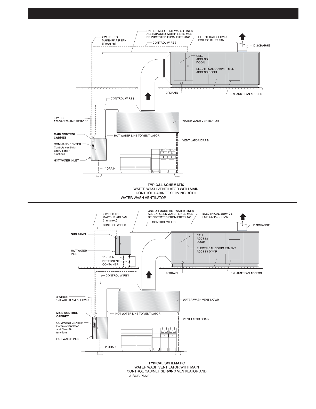
Wash Cycle
All Captive-Aire units include, as standard equipment, an
internal washdown system and control cabinet which when
activated washes the unit with hot detergent injected water
to remove the daily accumulation of smoke and grease particles. The washdown system and contols are interfaced with
the Captive-Aire Water Wash V entilator . There are two possible arrangements of controls for the operation of the V entilator and the C-ESP Unit as illustrated on page 9. In the first
arrangement, the Control Cabinet in the kitchen serves both
the Ventilator and the C-ESP U nit. The hot water solenoid
valves and detergent pump and container for both the V entilator and C-ESP Unit are located in this cabinet.In the second
arrangement there is a Control Cabinet for the ventilator electrically interfaced with a Sub Panel that serves the C-ESP
Unit. The hot water solenoid valves and detergent pump for
the C-ESP Unit are housed in the Sub Panel and the detergent container is located below or next to the panel. The detergent pump and container for the V entilator are both housed
in the main Control Cabinet located in the kitchen. In both
arrangements the Exhaust Fan, ESP, Wash Cycles and Fire
Cycle Functions are controlled by the V entilator Control Cabinet. The difference between the two is the location of the plumbing components.
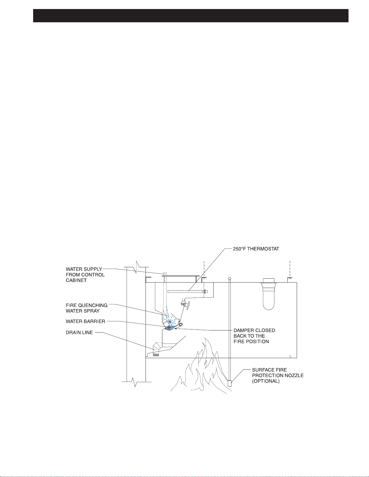
Fire Cycle
In the event of a fire, a 250o F. thermostat, mounted in the
airstream, will activate shutting off the exhaust fan and ESP
cells, and turning on the water sprays within the C-ESP Unit.
The fire cycle of the water wash ventilator will also activate at
this time. The water will run continually until the thermostat
cools below 250o F , and then run for another 2 minutes. At the
conclusion of this cool down cycle the exhaust fan may be
started by pushing "Start Fan".
SIDE VIEW
ELECTROSTATIC CELL
16
Page 16
C-ESP FIRE MODE
INTERNAL FIRE MODE
Automatic internal fire protection is accomplished by the
action of the thermostat(s), which is located in the filter section of the C-ESP. When the temperature of the conveying
airstream, which must pass over the thermostats, reaches
250°F , the system is activated, and the following occurs:
1. The damper begins closing back to the fire position, on
a Captive-Aire Ventilator, if so equipped, position 3 as
shown in Fig.4—stopping the combustion-supporting,
natural draft through the ventilator and creating a fire
barrier to contain the fire in the kitchen.
2. The exhaust fan is shut off. The supply fan is also shut
off.
3. Fire-smothering water spray is released into the interior
of the C-ESP through the spray nozzles.
4. The digital display reads "Fire In Hood, Fan Off, Wash
On" for approximately 5 seconds.
5. Then the digital display reads "Fire In Hood, Damper
Closing" for approximately 5 seconds.
6. Then the digital display reads "Fire In Hood, Notify Fire
Department". This display stays on until the thermostat
cools down below 250°F .
7. A red light on the Command Center illuminates.
8. If the Command Center is intertied with a building alarm
or monitoring system, a fire signal would be sent to that
system.
o
9. Upon cooling of the thermostat below 250
F, the Cool
Down Cycle starts. The water continues to spray during
the Cool Down Cycle (2 minutes). The damper moves to
the exhaust position, on a Captive-Aire Ventilator, if so
equipped.
10. While in the cool down cycle the digital display reads
"Cool Down Cycle, xxx sec. to end". xxx is the countdown in seconds until the wash turns off.
1 1. At the end of the cool down cycle the water turns off and
the digital display reads "Fan Off 12:00 (actual time),
Start Fan>F1". The damper closes to the wash position
in a Captive-Aire Ventilator , if so equipped.
NOTE: The water may be shut off prior to the end of the 2
minute cool down cycle by pushing the “Exit” button on the
CGPC-6000 Command Center . After the water has shut off,
the damper remains in the wash position on a Captive-Aire
Ventilator, if so equipped, until the “Start Fan” button is
pushed.
CAUTION:
In case of severe fire the thermostats located in the filter
section will activate. As a precautionary measure, it is recommended that the thermostats be replaced.
FIRE CYCLE
Captive-Aire V entilator
17
Page 17
C-ESP FIRE MODE
y!)
EXTERNAL FIRE MODE
An External Fire Mode is activated by the Pollution Control
Units or Ventilator’s Fire Suppression (Duct, Plenum, Surface/Appliance) system’s microswitch or contacts and/or an
optional break glass fire switch (see Figure 5). Terminals 4
& FS are used for the External Fire Mode, refer to wiring
diagram for details. The break glass fire switch, if used,
would normally be located at the exit of the kitchen. When
the External Fire Mode is activated, the following occurs:
1. The Exhaust Fan comes on immediately if it was off to
help remove smoke, heat, etc.
2. The Supply Fan shuts off immediately.
3. The digital display reads “Ext.FireActive” and alternates
between “Reset FireSwitch” and “Fan On, Wash On”.
4. A red light on the Command Center flashes.
5. After a 60-second delay , a fire smothering water spray
is released into the interior of the C-ESP and the Captive-Aire Ventilators, if so equipped, through the spray
nozzles.The 60-second delay allows the C-ESP's and
ventilator’s fire suppression system time to put out the
fire, before starting the water spray .
If the fire intensifies and the thermostat reaches 250°F, the
fire damper would then close on a Captive-Aire Ventilator , if
so equipped, and the exhaust fan would shut off. See Internal Fire Mode.
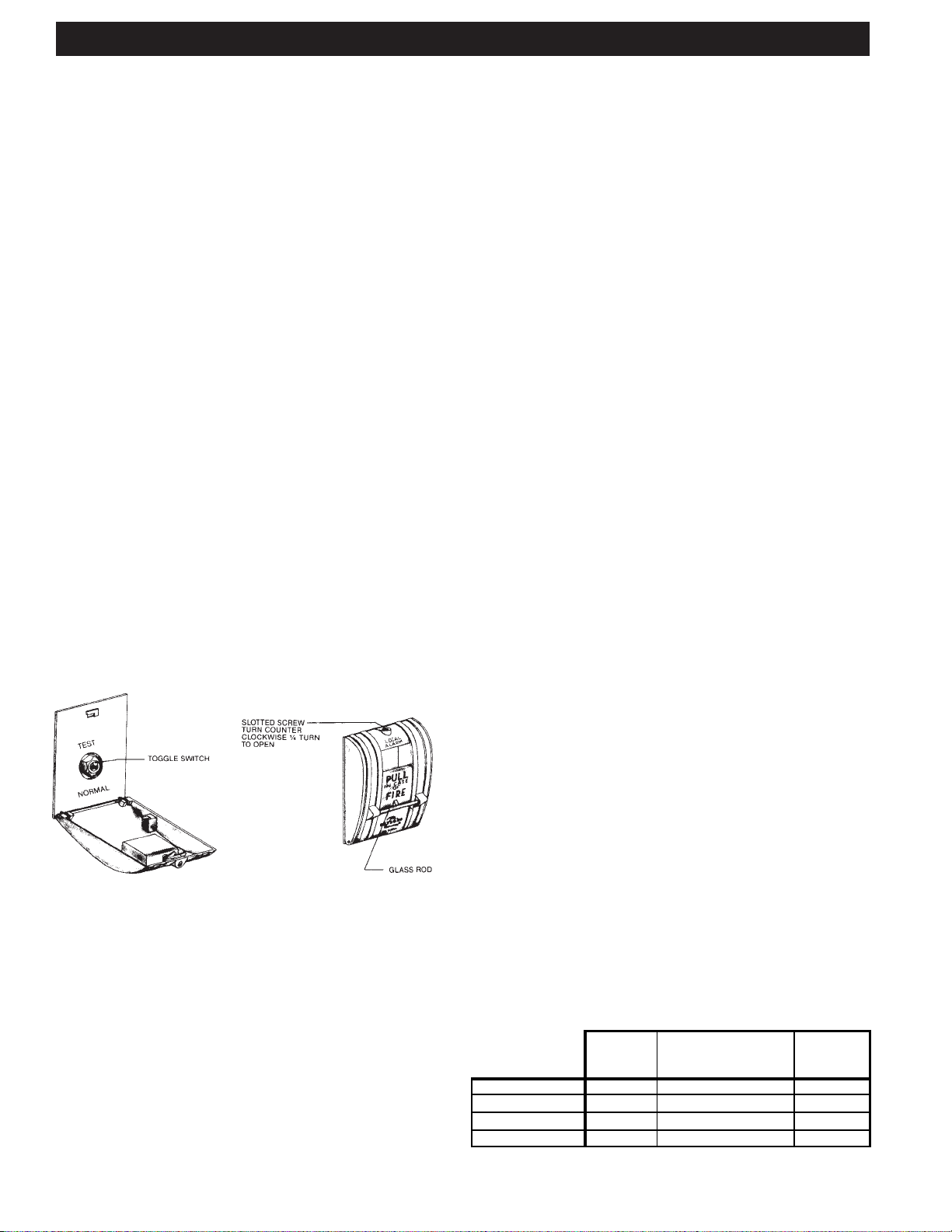
To resume normal operations, open the fire switch and flip the
toggle switch to the position marked “normal”. Replace the
glass rod and close the cover. Push either the “Start Fan”
or “Start Wash” button.
Summary of Both Fire Modes at the Same Time
1. Internal Fire Mode (until thermostat temperature
drops below 250°F)
2. Cool Down Cycle (for 2 minutes)
3. External Fire Mode (until the External Fire Switch is
reset)
TESTING INTERNAL FIRE MODE
The internal fire protection system may be tested periodically by pushing and holding for 20 seconds, the “Fire Test
Switch” located inside the electrical compartment of the
control cabinet. Pushing this switch duplicates thermostatic
action. CAUTION: Before pushing the “Fire Test Switch”,
check to see if the internal fire protection system is tied to
the building alarm system.
TO RESUME NORMAL OPERATION
1. To discontinue the 2 minute cool down cycle at any point
during the cycle, push the “Exit” F5 button on the
CGPC-6000 Command Center.
2. Push the “Start Fan” F1 button on the Command Center .
SURFACE FIRE PROTECTION
The National Fire Protection Association, NFPA-96 document requires fire extinguishing equipment over all grease
producing cooking equipment such as griddles, ranges, fryers, broilers, and woks. In addition, the system must protect
the interior of the ventilator and the exhaust duct.
The most common fire system is a wet chemical type. In the
event of a fire this system would normally be activated and
discharged prior to the ventilator’s internal fire protection. If
the fire is unusually severe or the surface fire protection system malfunctions, the ventilator’s internal fire protection system would activate, thus providing a second level of defense.
These systems may be intertied with the ventilator control
cabinet to activate the External Fire Mode.
FIG. 5
BREAK GLASS FIRE SWITCH
C-1357A SERIES
INTERNAL & EXTERNAL FIRE MODES AT THE SAME TIME
It is possible that both the Internal and External Fire modes
can be activated at the same time. If this occurs, the Internal
Fire Mode will override the External Fire mode until the
thermostat(s) cool below 250°F . At this point the Cool Down
Cycle will start counting down for 2 minutes. After the Cool
Down Cycle, the External Fire mode will start.
Special Note: If the control is in the Cool Down Cycle when
the External Fire mode is activated, the Cool Down Cycle
will finish counting down for 2 minutes, before switching to
the External Fire Mode.
FIRE MODE SUMMARY:
Note: The Damper Position applies to a Captive-Aire Ventilator, if so equipped.
INTERNAL
FIRE
Exhaust Fan OFF OFF ON
Supply Fan
Damper Position
Water Spray
OFF OFF OFF
FIRE EXHAUST EXHAUST
ON ON ON
COOL DOWN CYCLE
(for Internal Fire
Mode onl
EXTERNAL
FIRE
18
Page 18
DAILY OPERATION
DAIL Y OPERA TION
All functions of the
Captive-Aire Ventilator and C-ESP Unit,
such as starting the exhaust fan, starting the wash cycle,
etc., are controlled by the Command Center located on the
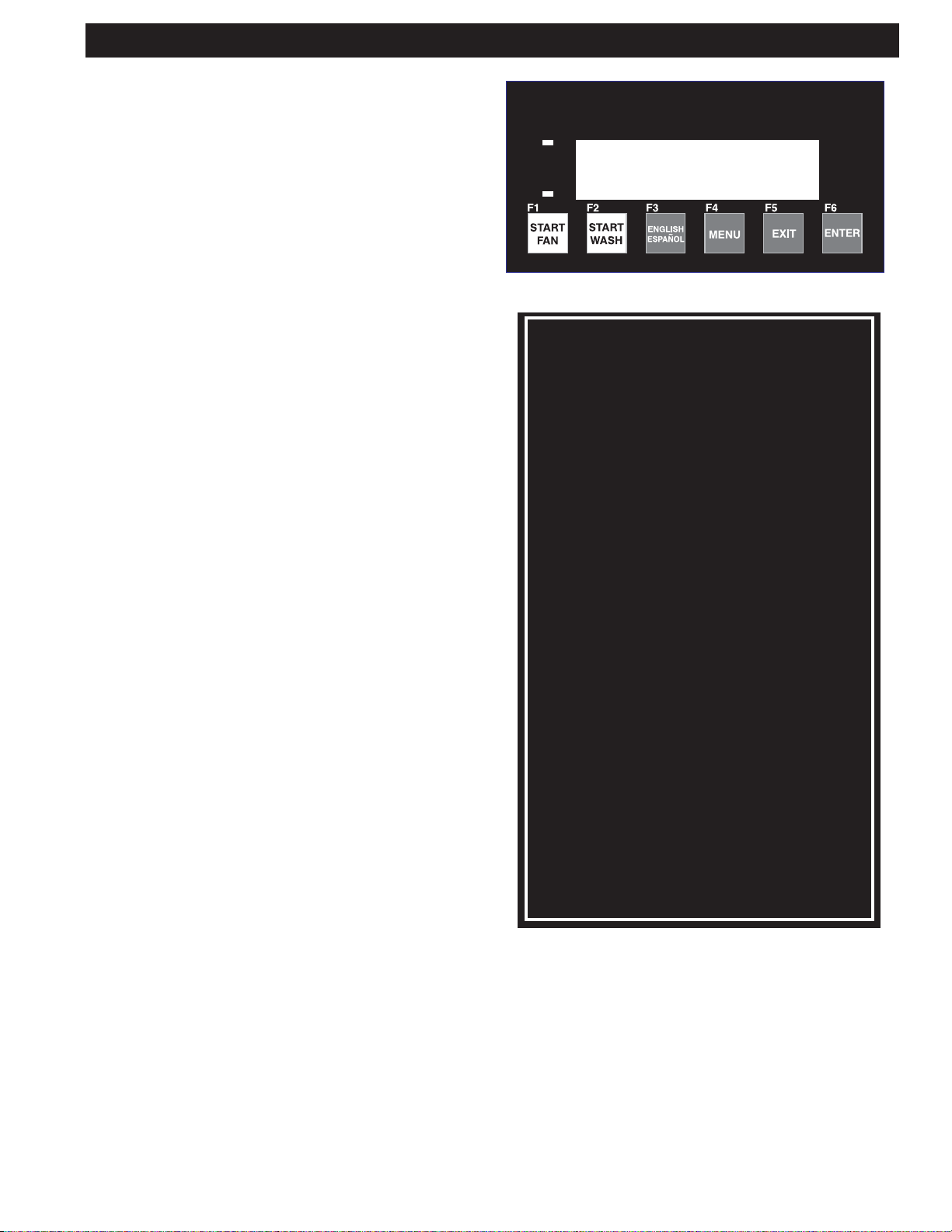
control cabinet. Refer to Pages 21 through 25 for detailed instructions on the operation of the Command Center.
COMMAND CENTER
MODEL CGPC-6000 SERIES
CONTROL CABINET
MODEL CGPC-6000-ESP SERIES
Starting the Exhaust Fan
To start the exhaust fan and C-ESP Unit push the “Start Fan”
button on the Command Center. If the Command Center is programmed to start the fan automatically, then the start button
does not need to be pushed. It is important to start the exhaust
fan before turning on the cooking equipment.
When the exhaust fan is activated the following occurs:
1.The damper on
Captive-Aire's Ventilator begins opening to
the exhaust position. (if applicable)
2.A green light on the Command Center illuminates.
3.The supply fan comes on.
4.The digital display reads "St arting Fan & Damper Opening"
for approximately 5 seconds. Then the digital display reads
"Starting Fan, xx Seconds to Fan On". xx is the coundown
in seconds until the exhaust fan comes on.
5. After the damper fully opens (elapsed time approximately
45 seconds) the unit exhaust fan starts.
6.The digital display then reads "Fan On 12:00" (current
time) and "Start Wash> F2".
7. The cell status light(s) will come on indicating that the
ESP cells are operating.
Stopping the Exhaust Fan and Starting the Wash Cycle
CAUTION: The cooking equipment must be shut off prior
to shutting off the exhaust fan. Failure to do this will cause
excessive heat buildup and could cause the surface fire
protection system to discharge.
To start the wash cycle push the “Start Wash” button on the
Command Center. If the Command Center is programmed to st art
the wash automatically , then the start button does not need to be
pushed. When the wash cycle is activated the following occurs:
1.The exhaust and supply fans shut off.
2. The ESP cells shut off.
3.The damper begins closing forward to the wash position.
This action takes approximately 45 seconds.
4.The digital display reads "Starting Wash, Damper Closing"
for approximately 45 seconds, then the digital display reads
"Starting Wash, Wash On in xx seconds". xx is the countdown in seconds to until the wash starts.
5.After the damper in the ventilator closes to the wash position,
the hot detergent injected water sprays come on to wash
away the grease collected during the day's operation. The wash
cycle stays on for the length of time programmed in the Command Center. The length of the wash cycle may be set between
3 and 9 minutes.Typical settings for the Captive-Aire Ventilator are 3 minutes for light-duty equipment, 5 minutes for medium-duty equipment and 9 minutes for heavy-duty equipment. The typical setting for the C-ESP unit is 5 minutes.
Refer to page 20 for details on setting the length of the
wash.
6. During a Ventilator wash, the digital display reads "Hood
Wash, Wash #1 xxx seconds." xxx is the countdown in
seconds until this portion of the wash is completed.
7. During an ESP wash, the digital display reads:
"ESP Wash 1, Wash #2 xxx seconds"
"Hot Water Heating, Wash #2 xxx seconds"
"ESP Wash 2, Wash #2 xxx seconds."
"Hot Water Heating, Wash #2 xxx seconds"
"ESP Rinse, Wash #2 xxx seconds"
xxx is the countdown in seconds until this portion of the
wash is completed.
8.The digital display now reads "Fan Off 12:00" (current time)
and Start Fan>F1.
After the wash cycle is completed, wipe the exposed front
surface of the damper at the air inlet slot, as well as other
exposed exterior surfaces.
In very heavy cooking operations it may be necessary to
wash the equipment more than once a day. This can be
done manually by pushing the “Start Wash” button.
NOTE: For proper operation of the wash system there must
be adequate water pressure and temperature.There is a pressure/temperature gauge inside the control cabinet.
Water Pressure 60 psi min. - 80 psi max.
Water temperature 160°F min. - 180°F max.
NOTE: Some control cabinets are equipped with a low detergent switch. If so equipped, the green light will flash if the
detergent tank is empty or if the detergent pump is malfunctioning and detergent is not pumping. The digital display reads
"Low Detergent" and the text alternates from "Fill Tank" and
"Check Pump". If the detergent tank is filled with water the
detergent switch will activate as if there is no detergent.
NOTE: The wash system is designed to remove daily accumulations of grease within the equipment. If the equipment
is not washed a minimum of once during a cooking day, a
grease buildup could accumulate which the wash system
cannot remove. If this occurs, it is recommended that the
equipment be put through several wash cycles by pushing
the “Start Wash” button on the Command Center. If this
does not remove the grease, it will be necessary to remove
the grease manually by using a scraping tool, such as a
putty knife, or retain the services of a commercial hood cleaning service to steam clean or pressure wash the system.
WARNING: Some commercial hood cleaning services blow a fire
retardant chemical into hood and duct systems. Fire retardant chemicals should never be applied to any portion of The Captive-Aire
Ventilator or ESP unit. If retardant is applied, it must be removed.
19
Page 19

DAILY OPERATION
g
Ventilator wash
The length of the ventilator wash is determined primarily by
the cooking equipment involved. Set the wash length from
3 – 9 minutes for light, medium or heavy duty equipment as
shown on the Recommended Ventilator Wash Time Chart
on this page. Adequate cleaning of the V entilator is dependent upon water pressure, water temperature, grease accumulation and hours of operation. It may be necessary to
increase the wash cycle time above recommendations depending upon these conditions.
C-ESP wash
The length of wash cycle time for the C-ESP Unit is normally set for 5 minutes as shown on the "Wash Cycle Sequence Charts". Set length of ESP washes to 5 minutes.
Delay
The "Wash Delay" is used to set the delay time between
each wash. A delay may be necessary to allow the hot water system to recover. The Wash Delay may be set from 1 –
99 minutes as required.
Rinse cycle
A rinse cycle is a hot water wash only (no detergent), and
occurs at various times during the wash cycle as shown on
the "Wash Cycle Sequence Charts". The rinse cycle time is
3 minutes.
TYPE OF COOKING RECOMMENDED WASH
EQUIPMENT TIMES (MINUTES)
LIGHT DUTY ........................................... 3
Ovens, steamers, and kettles
MEDIUM DUTY ....................................... 5
Braising pans/Tilting skillets, fryers,
griddles, grooved griddles, open burner
ranges, hot top ranges, and
conveyor ovens
HEAVY DUTY .......................................... 9
Gas and electric char broilers, upright
broilers, woks and conveyor broilers,
Solid fuel broilers
WASH CYCLE SEQUENCE CHARTS
All ESP Washes include the followin
1. ESP Wash 1 (3-9 minutes)
2. Delay (1-99 minutes)
3. ESP Wash 2 (3-9 minutes)
4. Delay (1-99 minutes)
5. ESP Rinse (3 minutes)
NOTES:
* ESP Wash 2 length = ESP Wash 1 length (always)
* ESP Rinse length = 3 minutes (always)
* Please note ALL “Delay” times are the same
steps:
TRAHCEMITHSAWROTALITNEVDEDNEMMOCER
All Hood Washes include the following:
1. Hood Wash (3-9 minutes)
Typical Wash Cycle for a Single Pass (1ESP) unit
with 1 Wash manifold:
1. ESP Wash 1 (5 minutes)
2. Delay (1 minute)
3. ESP Wash 2 (5 minutes)
4. Delay (1 minute)
5. ESP Rinse (3 minutes)
Total Elapsed Time: 15 minutes
Typical Wash Cycle for a Single Pass (1ESP) unit
with 2 Wash manifolds (DW):
Wash Manifold #1
1. ESP Wash 1 (5 minutes)
2. Delay (1 minute)
3. ESP Wash 2 (5 minutes)
4. Delay (1 minute)
5. ESP Rinse (3 minutes)
6. Delay (1 minute)
Wash Manifold #2
7. ESP Wash 1 (5 minutes)
8. Delay (1 minute)
9. ESP Wash 2 (5 minutes)
10. Delay (1 minute)
11. ESP Rinse (3 minutes)
Total Elapsed Time: 31 minutes
20
Page 20
MODEL CGPC-6000-ESP SERIES COMMAND CENTER - INSTRUCTIONS
General Description:
The CGPC-6000-ESP Command Center is designed to start
and stop the exhaust fan and wash up to 5 groups of ventilators and a C-ESP unit in sequence with a delay period
between each wash. A sequence wash may be necessary if
the building’s hot water system is not capable of supplying
the required volume of water at one given time.
The exhaust fan and wash sequence may be started Manu-
ally by pushing the “Start Fan” or “Start Wash” buttons, or
may be programmed for Automatic operation.
Programmed operations may include:
1.Starting the exhaust fan once within a 24-hour period.
2.Stopping the exhaust fan and starting the wash cycle sequence once within a 24-hour period.
3.Programming the length of the wash cycles and delay
periods between the wash cycles. The maximum length
of a wash cycle is 9 minutes. The maximum length of the
delay period is 99 minutes.
4.Skipping a day so the exhaust fan and wash cycle do not
operate for holidays or specific days within a 7-day week
when the kitchen is not operating.
The CGPC-6000-ESP Command Center provides information and programming for various functions by accessing nine
different menu catagories. An overview of the nine menu
items are as follows:
1.Cycle T ype: Toggles each wash solenoid between a Hood
wash and an ESP wash. Preset at factory and protected
by a password.
2.Detergent: Displays Toll-Free Number to order detergent:
800-286-2010.
3.Wash Length: Sets length of each wash cycle from 3 to 9
minutes.
4.Delay Time (for sequence wash units only): Sets delay
between washes from 1 minute to 99 minutes.
5.Set Clock: Day, hour and minutes.
6.AutoMode [M or A]: Sets the CGPC-6000-ESP to Manual
or Automatic modes. In Automatic mode, the CGPC-6000ESP will start the Fan and Wash at the preset times that
were set using the Set Wash Times option.
COMMAND CENTERCOMMAND CENTER
COMMAND CENTER
COMMAND CENTERCOMMAND CENTER
MODEL CGPC-6000 COMMAND CENTER
OPERATING INSTRUCTIONSOPERATING INSTRUCTIONS
OPERATING INSTRUCTIONS
OPERATING INSTRUCTIONSOPERATING INSTRUCTIONS
1. Push "Start Fan" before turning on cooking equipment.
Note: There is a 45 second delay after pushing the button
before the fan starts to allow the damper to open to the
"Exhaust" position.
2. At the end of the day, or whenever cooking is completed,
push "Start Wash". This will turn off the exhaust fan and
close the damper forward to the "Wash" position.
Note:Note:
Note: There is a 45 second delay after pushing the button
Note:Note:
before the wash cycle starts, to allow the damper, if so
equipped, to close to the "Wash" position. After closing, the
timed wash cycle begins. Damper stays closed until "Start
Fan" is pushed. Note: 24 hour kitchens must push "Start
Wash" at least once a day, or as needed for proper cleaning.
3. To set the length of the time for the wash cycle, press
"Menu", then press [F1] until "Wash Length" appears on
the display. Follow the instructions on the display to edit
the length of washes as necessary.
Note: Refer to the programming instructions on the inside
of this cabinet for more information on programming the
CGPC-6000 Command Center.
LOW DETERGENTLOW DETERGENT
LOW DETERGENT
The green light will flash and "Low Detergent" will be
displayed on the CGPC-6000 Command Center indicating
the detergent is low.
1. A flashing red light and the message "Ext. Fire Active"
indicates the control is in an External Fire Mode - exhaust
fan on, damper open, and water wash nozzles on.
2. A continuous red light and the message "Fire In Hood"
indicates the control is in an Internal Fire Mode - exhaust
fan off, damper closed, and water wash nozzles on.
LOW DETERGENTLOW DETERGENT
FIRE CONDITIONFIRE CONDITION
FIRE CONDITION
FIRE CONDITIONFIRE CONDITION
A = Automatic / M = Manual
Also allows individual days (Mon, Tues., etc.) to be set
ON or OFF when Automatic mode is selected.
7.Set Wash Times: Sets Start Times for Automatic start of
Fan and wash when CGPC-6000-ESP is set to Automatic
mode.
8.Wash Test: Runs through a complete Wash Cycle with
decreased times.
Damper Closing Time = 10 sec.
Wash Times = 10 sec.
Water Heating Time = 10 sec.
CGPC-6000-ESP COMMAND CENTER
Exits menu when finished.
9. Number of Washes: Preset at factory and protected with
a password.
Allows the number of washes to be changed from 1 to 13
(S1 to S13).
21
Page 21

MODEL CGPC-6000-ESP SERIES COMMAND CENTER - INSTRUCTIONS
Spanish (Español) Instructions:
The CGPC-6000-ESP Command Center has the ability to
display its commands and messages in either English or
Spanish (Español).
Press the "ENGLISH / ESP AÑOL" [F3] button to toggle the
language displayed from English to Spanish (Español) or
from Spanish (Español) to English.
NOTE: All messages displayed by pressing the "MENU"
[F4] button only appear in English. They will not appear in
Spanish (Español).
Using the Menu:
T o Enter the Menu, press the MENU button [F4].
T o navigate the Menu:
• Press [F1] to go to the Next menu item
• Press [F2] to go to the Previous menu item
• Press [F5], the EXIT button to exit the Menu
• Press [F6], the ENTER button to select a Menu item
1. Cycle Type
• Pressing [F6] [ENTER] will prompt for a password. It is
not necessary to change these settings. They are preset
at the factory .
2.Detergent
• Pressing [F6] [ENTER] will prompt for a password. It is
not necessary to change these settings. They are present
at the factory.
3.Wash Length
• Press [F6] [ENTER] to display the Length of Wash #1
• Press [F3] to Increase the Wash Time up to 9 Minutes
(Maximum)
• Press [F4] to Decrease the Wash Time down to 3 Min utes (Minimum)
• Press [F1] to adjust the Length of Wash #2 (if applicable)
• Press [F5] [EXIT] to return to the menu
• Note: Press [F1] to advance through all washes (ex.)
“-S2” has 2 washes)
4. Delay Time
• Press [F6] [ENTER] to display the Delay Time between
washes (Not used if there is only one wash)
• Press [F3] to Increase the Delay Time up to 99 Minutes
(Maximum)
• Press [F4] to Decrease the Delay Time down to 1 Minute
(Minimum)
• Press [F5] [EXIT] to return to the menu
5.Set Clock
• Press [F6] [ENTER] to display the current Day of the
Week (1=Sunday)
• Press [F3] to change to the next Day of the Week (1=Sun,
2=Mon, 3=Tues, etc.), keep pressing [F3] to cycle around
if necessary
• Press [F1] to go to the current Hour
• Press [F3] to increase the Hour, keep pressing [F3] to
cycle around if necessary
• Press [F1] to go to the current Minute
• Press [F3] to increase the Minute, keep pressing [F3] to
cycle around if necessary
• Press [F5] [EXIT] to return to the menu
6.AutoMode [A or M]
• Used to select [M]anual or [A]utomatic mode. If [A] is
displayed, the CGPC-6000-ESP is set to operate in Automatic mode. If [M] is displayed, the CGPC-6000-ESP is
set to operate in Manual mode.
• Press [F6] [ENTER] to display the “Set Mode” screen
• Press [F6] [ENTER] again to toggle between [M]anual
or [A]utomatic mode
Setting Which Days of the Week to Run:
• Press [F1] to select which days to run the CGPC-6000ESP in Automatic mode
• “Sun ON” or “Sun OFF” will display
• Press [F3] to set a day to “ON”. Set a day to “ON” in
order for the CGPC-6000-ESP to run on that day
• Press [F4] to set a day to “OFF”. Set a day to “OFF” in
order for the CGPC-6000-ESP NOT to run on that day
• Press [F1] to cycle through each day of the week [Sun –
Sat.]
• Press [F5] [EXIT] to return to the menu
7.Set WashTimes
• Only used when CGPC-6000-ESP is set to Automatic
mode
• Press [F6] [ENTER] to display the Start time for the Fan
on Sunday (Sun. Fan)
• Press [F3] to increase the Hour
• Press [F4] to increase the Minutes
• Press [F1] to go to the Start time for the Wash on Sun day (Sun.Wash)
• Set the time, using the same method described above
• Press [F1] to cycle through for each day of the week, for
the Start Times for the Fan and Wash
• Press [F5] [EXIT] to return to the menu
8.Wash Test
• Press [F6] [ENTER] to run the CGPC-6000-ESP through
a complete Wash cycle with decreased times
• After the Wash Test is complete, the CGPC-6000-ESP
will return to the Fan Off mode
9.Number of Washes
• Pressing [F6] [ENTER] will prompt for a password.
It is not necessary to change this value. It is preset at
the Factory.
22
Page 22

1. -epyTelcyC lliw]RETNE[]6F[gnisserP
l
.yrotcaf
[]5F[sserP TIXE unemehtotnruterot]
.2-tnegreteD forebmunenohpniatbooT
015-G
]6F[sserP ]RETNE[ enohPehtyalpsidot
]5F[sserP ]
.3htgneLhsaWteSoT
]6F[sserP ]RETNE[ fohtgneLehtyalpsidot
1#hsaW
ro
(setuniM3ot
1F[sserP
)elbacilppa
]5F[sserP ]TIXE[ unemehtotnruterot
.4emiTyaleDteSoT
sserP]6F[ ]RETNE[ emiTyaleDehtyalpsidot
)hsaw
sserP
ro
]5F[sserP ]TIXE[ unemehtotnruterot
MODEL CGPC-6000-ESP SERIES MENU FUNCTIONS
NOITCNUFUNEM SDAERYALPSID
otyrasssecentonsitI.drowssaparoftpmorp
hT.sgnittesesehtegnahc
teD)2("litnu]1F[sserP
TIXE[ unemehtotnruterot
)mumixaM(setuniM
)muminiM
ehtfidesutoN(sehsawneewteb
mumixaM(setuniM
)muminiM(etuniM1ot
ehttateserperaye
epyTelcyC)1(
sraeppa"epyTelcyC)1("litnu]1F[sserP
tnegreteD)2(
sraeppa"tnegre
:tnegreteDroF
0102-682-008-1:tnegreteDredrootrebmuN
sraeppa"htgneLhsaW)3("litnu]1F[sserP
9otpuemiThsaWehtesaercnIot]3F[sserP
nwodemiThsaWehtesaerceDot]4F[sserP
fi(2#hsaWfohtgneLehttsujdaot]
sraeppa"emiTyaleD)4("litnu]1F[sserP
enoylnosier
99otpuemiTyaleDehtesaercnIot]3F[
nwodemiTyaleDehtesaerceDot]4F[sserP
htgneLhsaW)3(
emiTyaleD)4(
goT(verP>2FtxeN>1F
retnE>6FtixE>5F)htiwselg
retnE>6FtixE>5F)htiwselggoT(verP>2FtxeN>1F
tixE>5F)htiwselggoT(0102-682-008-1
F)htiwselggoT(verP>2FtxeN>1F
lortnoclaitneuqeSasaputessi
tixE>5F)htiwselggoT(nwoD>4FpU>3F
retnE>6FtixE>5
).niM9ot.niM3morfegnaR(NIM3:emiT1hsaW
tixE>5FtxeN>1F)htiwselggoT(nwoD>4FpU>3F
ortnocfi.cte,2#hsaWtxeNotseogtxeN>1FgnisserP*
retnE>6FtixE>5F)htiwselggoT(verP>2FtxeN>1F
).niM99ot.niM1morfegnaR(niM1:emiTyaleD
.5kcolCteSoT
]6F[sserP ]RETNE[ yaDtnerrucehtyalpsidot
)yadnuS=1(keeWehtfo
uS=1(keeW
ruoHtnerrucehtotogot]1F[sserP7:ruoH
aercniot]3F[sserP
yrassecenfidnuoraelcycot]3F[
]5F[sserP ]TIXE[ un
emehtotnruterot
sraeppa"kcolCteS)5("litnu]1F[sserP
yaD
ehtfoyaDtxenehtotegnahcot]3F[sserP
peek,).cte,seuT=3,noM=2,n
yrassecenfidnuoraelcycot]3F[gnisserp
gnisserppeek,ruoHehtes
kcolCteS)5(
FtixE>5F)htiwselggoT(verP>2FtxeN>1F
yadnuS=16
retnE>6
verP>2FtxeN>1F)htiwselggoT(tixE>5FpU>3F
verP>2FtxeN>1F)htiwselggoT(tixE>5FpU>3F
23
Page 23

MODEL CGPC-6000-ESP SERIES MENU FUNCTIONS
6. -]MroA[edoMotuA launa]M[tcelesotdesU
1F[sserP
]6F[sserP ]RETNE[ ”edoMteS“ehtyalpsidot
n
eercs
NOITCNUFUNEM SDAERYALPSID
eht,deyalpsidsi]A[fI.edomcitamotu]A[ro
nietarepoottessi0006-C
.edomlaunaMnietarepo
.edomcitamotuA
ottessi0006-Ceht,deyalpsidsi]M[fI
sraeppa"edoMotuA)6("litnu]
]M[edoMotuA)6(
verP>2FtxeN>1FretnE>6FtixE>5F)htiwselggoT(
rof"A"rolaunaMrof"M"rehtieebnaC(]M[edoMteS
)citamotuA
]6F[sserP ]RETNE[ neewtebelggototniaga
motu]A[rolauna]M[
erP
y
ad
yadtaht
cot]1F[sserP
].taS–nuS[keew
]5F[sserP ]TIXE[ unemehtotnruterot
.7-semiThsaWteS si0006-CnehwylnodesU
motuAottes
]6F[sserP ]RETNE[ emittratSehtyalpsidot
serP
[sserP
yadnuSnohsaW hsaW.nuS( )
evobadebircsed
hsaW
]5F[sserP ]TIXE[ unemehtotnruterot
.8tseThsaW
8("litnu]1F[sserP
]6F[sserP ]RETNE[ 0006-Cehtnurot
semitdesaerced
.9sehsaWforebmuNteS
]5F[sserP ]TIXE[ une
edomcita
nurotkeewehtfoyadhcihwgnitteS
ehtnurotsyadhcihwtcelesot]1F[sserP
edomcitamotuAni0006-C
yalpsidlliw”FFOnuS“ro”NOnuS“
otyadateS.”NO“otyadatesot]3F[ss
tahtnonurot0006-Cehtrofredroni”NO“
otyadateS.”FFO“otyadatesot]4F[sserP
nonurotTON0006-Cehtrofredroni”FFO“
ehtfoyadhcaehguorhtelcy
.edomcita
sraeppa"emiThsaWteS)7("litnu]1F[sserP
yadnuSnonaFehtrof naF.nuS( )]42:41[naF.nuS
ruoHehtesaercniot]3F[s
setuniMehtesaercniot]4F[sserP tixE>5FtxeN>1F)htiwselggoT(.niM>4FruoH>3F
ehtrofemittratSehtotogot]1F
dohtememasehtgnisu,emitehtteS
orhtelcycot]1F[sserP
h
tiwelcychsaWetelpmocahguorht
a"sehsaWfo#)9("litnu]1F[sserP
mehtotnruterot
foyadhcaerofhgu
dnanaFehtrofsemiTtratSehtrof,keeweht
sraeppa"tseThsaW)
sraepp
>1F
tixE>5FtxeN>1F)htiwselggoT(na]M[/otu]A[>6F
semiThsaWteS)7(
retnE>6FtixE>5F)htiwselggoT(verP>2FtxeN
]42:41[hsaW.nuS
tixE>5FtxeN>1F)htiwselggoT(.niM>4FruoH>3F
gnisserP* txeN>1F cte,emitnaFtratStxeNotseog-
tseThsaW)8(
retnE>6FtixE>5F)htiwselggoT(verP>2FtxeN>1F
gnisserP* retnE>6F tseThsaWehtstratS-
sehsaWfo#)9(
retnE>6FtixE>5F)htiwselggoT(verP>2FtxeN>1F
24
Page 24

TIME CLOCK OPERATION
AutoMode is used to have CGPC-6000-ESP start the exhaust/
supply fans automatically, once per day. The AutoMode also
stops the fans and starts the wash cycle, once per day.
T o use the AutoMode:
1. Set Wash Length(s) (Menu item #3)
Set length of each wash cycle, from 3 minutes to 9 minutes
2. Set Delay Time between washes, if control has more than
one wash solenoid (Menu item #4)
Set amount of time to wait between washes, from 1
minute to 99 minutes
3. Set Clock (Menu item #5)
Please note that the clock is a 24-hour clock.
Example: 1:00 PM = 13:00
Set the current day of the week.
Example: 1 = Sun. 2 = Mon. 3 = Tues, etc.
4. Turn AutoMode ON (Menu item #6)
Pressing (F6) Enter will toggle between [A]utomatic and
[M]anual modes
After it is set to [A]utomatic mode, set which days of
the week the Exhaust/Supply Fan will run - setting a
day to "ON" means the Exhaust/Supply Fan will start
on that day , and the Wash will run.
Example: Sun ON
Mon OFF
Tues ON
5. Set Wash Times, set start times for Fans & Wash (Menu
item #7).
Set the time for the Fans to Start for each day of the
week.
Example: Sun. Fan 5:00
Mon.Fan 5:00
Set the time for the Wash to Start for each day of the
week.
Example: Sun.Wash 22:00
Mon.Wash 22:00
25
Page 25

DETERGENT PUMP OPERATION
The Captive-Aire Ventilator detergent pump is an integral part
of the wash-down system of The Captive-Aire V entilator and
C-ESP unit. The pump is located within the control cabinet
unless otherwise specified. (Refer to schematics on Pages
46 through 47.)
OPERA TION
The detergent pump is started when the wash cycle begins.
The pump draws detergent up from the detergent tank, pushing it through the copper tubing and into the hot water line
serving the ventilator.
NOTE: Some control cabinets are equipped with a low detergent switch. If so equipped, the green light will flash if the
detergent tank is empty or if the detergent pump is malfunctioning and detergent is not pumping. The digital display reads
"Low Detergent" and the text alternates from "Fill T ank" and
"Check Pump". If the detergent tank is filled with water the
detergent switch will activate as if there is no detergent.
Initial Operation
To prime and operate the pump for the first time, it is recommended that water be used instead of detergent to prevent detergent from spilling in case of leaks at the system’s fittings.
Priming The Pump
The detergent pump is self-priming. Push the pump test switch,
located on the junction box of the motor, and hold down until
liquid climbs up the vinyl tubing and fills the pump head. The
pump will be operating properly when both upper and lower
poppet checks can be seen moving up and down slightly . If
the pump does not self-prime, an air lock may have developed
within the pump head and the following action should be taken:
1.Hold down pump test switch and loosen top cap slightly
to allow air to be pushed out. Repeat as necessary until
liquid climbs up tube and fills pump head.
Note: Do not over tighten cap or damage to the pump
head will occur.
Depending upon these factors, it may be necessary to
adjust the detergent flow. Adjustment may be accomplished by changing the cam to a different size. To change
the cam:
1.Loosen Allen set screw on brass cam.
2.Remove cam and replace with next size as required.
3.Cam #1 minimum setting. Cam #4 maximum setting.
NOTE: Cams are available from Captive-Aire Systems or
your Certified Service Agency .
PREVENTIVE MAINTENANCE
As with any piece of fine equipment, a reasonable amount of
care must be taken to keep it in good working order:
1.Caution should be taken not to spill detergent on the exterior of the pump.
2.A periodic check should be made of all fittings to
guarantee their tightness.
NOTE: The detergent pump motor has sealed bearings and
will not require lubrication.
)lairepmI(
lortnoC
tenibaC
"2/11
"4/32#1.56.514.31.627.55.639.7
"13#0.68.719.36.925.64.141.9
"4/11
"2/11&
yrotcaF
maC
eziSepiP
gnitteS
#2.36.91.21.615.35.229.4
4#3.68.811.43.138.68.346.9
reP.zO
ta.niM
ISP04
retaW
erusserP
setuniM3setuniM5setuniM9
.zO
.laG
reP
reP
yaD
.oM
TRAHCNOITPMUSNOCTNEGRETED
HTGNELELCYCHSAW
.zO
.laG
reP
yaD
.zO
reP
reP
.oM
reP
yaD
.laG
.oM
2.If the pump still does not work properly , check the following:
A. Foot valve should be clean and immersed in the liquid.
B. Check all fittings to ensure an airtight system.
C. Poppet checks within the foot valve, pump head and
brass check valve should be clean and operating freely .
D. Detergent lines should be free and clear.
DETERGENT FLOW
Detergent flow is initially factory set according to the pipe
size of the control cabinet (refer to Detergent Consumption
chart). Generally , the factory setting will be suf ficient to provide adequate cleaning of the ventilator. However , adequate
cleaning is dependent upon a number of factors:
1.T emperature of hot water 4.Wash cycle time
2.Water pressure cycle 5.Frequency of wash cycle
3. Daily grease accumulation 6.T ype of detergent
26
Page 26

DETERGENT FOR THE WASH SYSTEM
FORMULA G-510 is the only cleaner recommended by CaptiveAire Systems for use in the washdown system of The CaptiveAire V entilator. FORMULA G-510 is a concentrated colloid cleaner
specially formulated to remove the daily accumulation of grease
inside The Captive-Aire Ventilator without damaging the rubber
and synthetic parts of the detergent pumping system. FORMULA
G-510 is biodegradable, safe for kitchen personnel, and has a
variety of uses.
DILUTION OF FORMULA G-510 FOR
VENTILA TOR CLEANING
Normal Cleaning
For ventilators covering cooking equipment such as broilers,
griddles, fryers, or any other heavy grease producing equipment, fill the detergent tank with full strength FORMULA G-
510.
Light-Duty Cleaning
For ventilators covering light grease producing equipment
such as ovens, kettles, steamers and ranges, fill the detergent tank with a mixture of one part FORMULA G-510 to one
part water .
Cleaning the Ventilator Exterior
Mix one part FORMULA G-510 to twenty parts water in hand
spray bottle. Spray on and wipe of f. NOTE: Once a day , this
same solution should be used to clean the front of the fire
damper and main grease extracting baffle.
FOR OTHER CLEANING JOBS
The colloidal action of FORMULA G-510 makes it a cleaner
especially well-suited for use in kitchens. The colloids break
up dirt and grease into millions of tiny particles that constantly repel each other . These particles cannot recombine
or redeposit on a surface and are, therefore, easily washed
away . FORMULA G-510 is biodegradable and contains no
harsh chemicals, yet offers outstanding performance on the
toughest cleaning jobs.
LIMITED WARRANTY
G-510 CHEMICAL DIVISION warrants that FORMULA G510 will not cause cleansing agent damage to the rubber
and synthetic parts of the injection pump (“O” rings, diaphragms, washers, tubing, and other such parts) used with
The Captive-Aire V entilator , Heat Reclaim Unit, or Pollution
Control Equipment. G-510 CHEMICAL DIVISION’S obligation under this warranty and any warranties implied by law
shall be limited to repairing or replacing, at its option, any of
said parts which G-510 CHEMICAL DIVISION'S examination shall disclose to its satisfaction to have been damaged
by the use of FORMULA G-510 for the life of the detergent
pumping system. This warranty shall not cover damages
caused by any other detergent. The use of any other detergent shall void this warranty.
All repairs and replacement parts under this warranty shall
be F .O.B. G-510 CHEMICAL DIVISION’S factory . The owner
shall pay the necessary freight and delivery charges; also
removal and installation costs. Any federal, state or local
taxes are also extra. Requests for repairs or replacement
parts should be made to 20/10 Products Inc., PO Box
7609, Salem, OR 97303.
This is the sole warranty with respect to FORMULA G-
510. G-510 CHEMICAL DIVISION MAKES NO OTHER
WARRANTY OF ANY KIND WHATSOEVER, EXPRESSED OR IMPLIED, AND ALL IMPLIED WARRANTIES OF MERCHANTABILITY AND FITNESS FOR A
P ARTICULAR PURPOSE WHICH EXCEED THE AFORESAID OBLIGATION ARE HEREBY DISCLAIMED AND
EXCLUDED FROM THIS AGREEMENT . G-510 CHEMICAL DIVISION SHALL NOT BE RESPONSIBLE FOR INCIDENTAL OR CONSEQUENTIAL DAMAGES RESUL TING FROM A BREACH OF THIS W ARRANTY .
Use a mixture of one part FORMULA G-510 to twenty parts
water for:
VINYL/PLASTIC/WALLS...Removes dirt, grease,
food deposits and fingerprints.
REFRIGERA TORS...Removes dirt, spilled milk, blood, mildew and objectionable odors.
RESTROOMS...Add a disinfectant to clean all fixtures,
walls, floors, etc.
Use a mixture of one part FORMULA G-510 to five parts water
for extremely heavy grease build-up, such as on the floor and
on equipment around deep-fryers. Spray on and rinse or wipe
off. For extremely soiled areas, gentle agitation, followed by a
soaking period, will result in more thorough cleaning.
DON’T be afraid to experiment with FORMULA G-510 because it contains no phosphates, nitrates, enzymes, sulfates, sulfonates or silicates.
IMPORTANT
If a cleansing agent other than FORMULA G-510 is used
with The Captive-Aire V entilator injection pump, it is recommended that a warranty similar to the above be obtained
from the manufacturer of said product.
For name and address of the nearest FORMULA G-510
distributor contact:
20/10 Products Inc.
P.O. Box 7609
Salem, OR 97303
Phone: 800-286-2010
FAX: 503-363-4296
E-Mail:twentyten@juno.com
27
Page 27

ESP SECTION - PREVENTIVE MAINTENANCE
Proper maintenance is the key element in keeping the
Captive-Aire Unit operating at design efficiency . The following outlines recommended maintenance.
CELL ROT A TION
T o achieve maximum smoke removal it is recommended that
the ESP cells within the unit be rotated out, using spare cells
provided. A soak tank (optional, refer to illustration on page
31) is recommended for each spare cell (optional) to facili-
tate cleaning. The frequency of rotation is based primarily on
the type of cooking equipment the unit is serving and also on
the number of hours per day of operation, hot water temperature and pressure, and the type of detergent used. The recommended cell rotation frequency is shown in the chart at
right.
The number of ESP cells a unit has is dictated by the air
volume (CFM) of the unit. The illustrations on page 30 shows
the standard cell configurations from a one cell to a 16 cell
unit. There are two types of cells, “Outer cells” and “Inner
cells” marked “O” and “I” on the cell configuration illustrations
on page 30 and marked on the nameplate of the cell shown
on page 48. The differences between the two are shown on
the illustrations on page 29. The number of “Inner” and “Outer”
(optional) spare cells provided varies with the size of the unit.
Refer to the spare cell chart on page 31.
NOTE: Some units are equipped with a second row of ESP
cells, referred to as double pass and denoted in the model
number by the suffix "2ESP". Refer to the cross section
illustration on page 30 for an example. Additional spare cells
are not provided for double pass units as the second pass
does not get as dirty as the first pass.
In order to have effective cell rotation, it is important to set
up a system so that you know which cell is next to be rotated out. Referring to the cell configuration illustration on
page 30, a number has been assigned to each cell space.
Use these numbers in developing a system for rotation.
CELL ROT ATION PROCEDURE
1.Remove the spare cell from the soak tank and drain the
water. It may be necessary to hose the t ank interior to
remove grease and smoke residue.
2.Open the electrical compartment and cell access doors.
Power will automatically disconnect and de-energize
the cells.
3.Remove the three (3) wires from the outer cell by pulling
forward from the cell terminals. Push the wire connectors onto holding terminals.
4.Pull the cell straight out slowly.
CAUTION: Each cell weighs 53 lbs. and may be awkward to handle, particularly cells in the upper racks.
It is highly recommended that a heavy duty steel
wheeled ladder be used in removing the upper cells.
Extreme care must be taken to avoid damaging the
cell. Do not grip or push on the cell plates or the ionizer wires.
TRAHCYCNEUQERFNOITATORDETSEGGUSLLECPSE
TYPE OF COOKING ROTATION FREQUENCY
EQUIPMENT IN DAYS
LIGHT DUTY ........................................... 30
Ovens, steamers, and kettles
MEDIUM DUTY ....................................... 21
Braising pans/Tilting skillets,
fryers, griddles, grooved griddles,
open burner ranges, hot top ranges,
and conveyor ovens
HEAVY DUTY .......................................... 14
Gas and electric char broilers, upright
broilers, woks and conveyor broilers
EXTRA HEAVY DUTY ............................ 7
Solid fuel broilers
5.After the appropriate cells have been removed, replace them
with clean cells taken from the soak tank. Caution - Be sure
to replace the cell with the airflow pointing in the same direction of airflow as marked on the front of the cell access door.
6.Re-connect the 3 lead wires to the terminals on the cell.
Close the cell and electrical compartment doors.
7.Place the dirty cells in the soak tanks. Fill with hot water
and add Formula G-510 at a ratio of one part detergent to
ten parts water. Leave the cell in the tank until the next
rotation.
WEEKL Y MAINTENANCE
The detergent tank should be checked at least weekly and filled
with recommended detergent. (Refer to page 27.) The Control
Cabinet may be equipped with an optional low detergent switch
and when the detergent tank is empty or the pump is not pumping the green light on the Command Center will flash and
"Low Detergent" will be displayed on the Command Center.
Refer to page 26 for detailed information on the detergent pump.
SIX MONTH MAINTENANCE
Every 6 months remove and inspect the ESP cells and check
the following:
1.Check all the spray nozzles to ensure that they are spraying properly .
2.Examine the ESP Cells for the following:
a.Check for any missing or loose ionizer wires. Replace
wires as necessary . (Refer to Ionizing Wire Replacement
illustration).
b.Check for any physical damage to the collector plates.
Plates can become bent at their corners and must be
straightened to maintain proper plate spacing.
c.Check for any grease film build-up on the high voltage
insulators (white porcelain material.) Clean the insulators to avoid possible high voltage “tracking” to the ground.
d.Check for any material which has lodged or built up
between adjacent plates.
28
Page 28

ESP SECTION - PREVENTIVE MAINTENANCE
L
INNER CELL
SMOKE POLLUTION CONTROL CELL
MODELNO.: C-24-I
WARNING: CELL AND UNIT AIRFLOW DIRECTION MUST MATCH
High Voltage - Be sure power is off and high voltage circuit is grounded before
touching the wire terminals. Refer to the Gaylord “ClearAire” Technical Manual
CAUTION
for complete operation & maintenance instructions.
AIRFLOW
gent harmful to aluminum will void the warranty and may cause permanent damage.
Cleaning Cell - The smoke pollution control cells in this system are made of aluminum. Use of a deterservicing. When handling cell, hold framework only. Do not touch the plates as they could be damaged.
Cell Removal - This cell weighs more than 52lbs. Handle with care when removing for cleaning and
AIRFLOW
for complete operation & maintenance instructions.
CAUTION
touching the wire terminals. Refer to the Gaylord “ClearAire” Technical Manual
High Voltage - Be sure power is off and high voltage circuit is grounded before
WARNING: CELL AND UNIT AIRFLOW DIRECTION MUST MATCH
MODELNO.: C-24-I
SMOKE POLLUTION CONTROL CELL
INNER CELL
OUTER CELL
Cell Removal - This cell weighs more than 52lbs. Handle with care when removing for cleaning and
servicing. When handling cell, hold framework only. Do not touch the plates as they could be damaged.
Cleaning Cell - The smoke pollution control cells in this system are made of aluminum. Use of a detergent harmful to aluminum will void the warranty and may cause permanent damage.
SMOKE POLLUTION CONTROL CELL
WARNING: CELL AND UNIT AIRFLOW DIRECTION MUST MATCH
High Voltage - Be sure power is off and high voltage circuit is grounded before
touching the wire terminals. Refer to the Gaylord “ClearAire” Technical Manual
CAUTION
for complete operation & maintenance instructions.
Cell Removal - This cell weighs more than 52lbs. Handle with care when removing for cleaning and
servicing. When handling cell, hold framework only. Do not touch the plates as they could be damaged.
Cleaning Cell - The smoke pollution control cells in this system are made of aluminum. Use of a detergent harmful to aluminum will void the warranty and may cause permanent damage.
INNER CELL
MODELNO.: C-24-I
AIRFLOW
gent harmful to aluminum will void the warranty and may cause permanent damage.
Cleaning Cell - The smoke pollution control cells in this system are made of aluminum. Use of a deterservicing. When handling cell, hold framework only. Do not touch the plates as they could be damaged.
Cell Removal - This cell weighs more than 52lbs. Handle with care when removing for cleaning and
AIRFLOW
for complete operation & maintenance instructions.
CAUTION
touching the wire terminals. Refer to the Gaylord “ClearAire” Technical Manual
High Voltage - Be sure power is off and high voltage circuit is grounded before
WARNING: CELL AND UNIT AIRFLOW DIRECTION MUST MATCH
MODELNO.: C-24-I
SMOKE POLLUTION CONTROL CELL
INNER CELL
INNER CELL
Replacing the Ionizing Wire
1.Remove all of the broken wire from the cell mounting brackets.
2.Install the new wire:
A. Insert hook of one spring into hole.
B. Use long-nose pliers and carefully pull second spring
until hook can be secured in mounting bracket hole.
CAUTION: The electrostatic cells are made of aluminum. DO
NOT use any type of detergent that may attack aluminum or
anodizing. It is highly recommended that Formula G-510
Colloid Cleaner be used in the wash system. Refer to Page
27 for details.
INSERT HOOK OF ONE
A
SPRING INTO HOLE
IONIZING
MOUNTING
BRACKET
WIRE
Note: See page 63 for part numbers
B
PULL SECOND SPRING UNTI
HOOK CAN BE SECURED IN
MOUNTING BRACKET HOLE
IONIZING WIRE REPLACEMENT
29
Page 29

ESP SECTION - CELL CONFIGURATION
KEY
O = OUTER CELL
I = INNER CELL
# = ASSIGNED CELL
SP ACE NUMBER
CONFIGURA TION = W x H
Note: Illustration of cells configured with
airflow coming towards you.
30
AIRFLOW
"2 ESP"
Page 30

ESP SECTION - SPARE CELLS
TRAHCLLECERAPS
SLLECERAPS
TINUFOEZIS
DEDIVORP
RETUO
LLEC
TINULLEC1
TINULLEC2
TINULLEC3
TINULLEC4
TINULLEC6
TINULLEC8
T
INULLEC9
TINULLEC21
TINULLEC61
:ETON fowordnocesahtiwdeppiuqeerastinuemoS
ssap
eht
sastinu
.ssaptsrif
1
1
1
1
1
2
2
2
3
82egapnonoitartsullinoitces
recommended
RENNI
LLEC
0
1
1
1
2
2
2
2
3
ssorcehtotrefeR.ssapelbuodsaotderrefer,sllecPSE
.elpmaxenarof
elbuodroftonerasllecerapslanoitiddA
saytridsategtonseodssapdnoceseht
CELL SOAK T ANK
31
Page 31

.
l
l
r
t
t
l
f
ESP SECTION - TROUBLE-SHOOTING
Smoke Removal
Proper voltage through the ESP cells is essential for maximum smoke removal. There is one or more power supply
transformers located in the electrical compartment of the CESP unit. The quantity is dictated by the number of cells,
but typically there is one transformer(s) for every 2 or 3 cellls.
The transformer(s) outputs 5,000 volts DC to the repelling
plates of the cell and 10,000 volts DC to the Ionizing wires.
The voltage of each transformer is monitored by a green “ESP
ON” light located on the main Control Cabinet, and on the
ESP Power Pack door of the unit electrical compartment.
Operation of these lights is as follows:
Solid Green Light - This is a normal condition indicating
that the ESP cells are operating properly .
Fluctuating Green Light - Normally a fluctuating green light
is a temporary condition, lasting until the cells are dry, immediately following a wash cycle. This is caused by moisture left between the cell plates which will evaporate.
Green Light Off - A green light off indicates one of the following conditions exists:
melborPelbissoPnoituloSelbissoP
ehtotrewopoN
remrofsnart
nihctiwsytefaS
sideht
otgnittegtonegatloV
slleceht
.1
.2
.3
.4
.noitisopno
noitisoptcennoc
.dehctal
.1
.2
erusneottnemtrapmoc
.retnecdnammoceht
.sllecrennieht
detcennoceraseriw
ehtedisniesufpmA4ehtkcehC
retneCdnammoCCPSR-0005-C
r.ekaerbtiucricniamehtkcehC
hctiwsecivreselggotehtkcehC
acirtceleriAraelCehtedisni
ehtniis ti
nonottub”naFtratS“ehthsuP
acirtcelednallecehtkcehC
otsroodsseccatnemtrapmoc
dnadesolcerayehttahterusne
etuollatahterusneotkcehC
tsniagathgitnidehsuperasllec
daelllatahterusneotkcehC
.sllecehtot
SAFETY SWITCH
There is one or more safety switches located behind the cell access door and the electrical compartment access door. The safety
switch, when released by opening one of the doors, shuts off the
power to the power supply transformer and bleeds power from
the cells, by grounding the cell power wires. To check the
safety switch for proper operation, open the doors and push the
safety switch plunger and release. A definite “arc” should occur
within the safety switch as the plunger is released.
ESP CELL VOL T AGE TEST
T o check for proper operation of each cell, proceed as follows:
1.Open electrical compartment door .
2.Remove the 5KV and 10KV volt lead wires from the first cell.
3.By hand, push in door safety switch. Now measure voltage from ground to the 5KV volt lead wire and then from
ground to the 10KV volt lead wire. If proper voltage is obtained, this is the cell that is causing the reduced voltage.
If the voltage is below normal, pull the leads on the next cell
and repeat steps 1 through 3. Continue this procedure with
each cell until the non-functioning cell is found. Inspect the
non-functioning cell for any physical damage such as loose
or broken ionizer wires, foreign material, or local grease accumulation which may be grounding between positive and
negative collector plates.
If there is still a reduced voltage after all the leads have been
removed from the cells, the problem is in the high voltage
power supply . Recheck both the cell door safety switch and
electrical compartment door safety switch for proper operation. Switch should “arc” and failure to arc could indicate a
defective power supply transformer or 120 volt micro switch
mounted within the safety switch.
If all these tests fail to find the problem area, check output
voltage of the transformer as described on the next page.
.llecytluaF
.1
.2
.3
:erasesuacelbissoP
setalpnopudliubesaerG
.srotalusninialecropro
degdol
lairetamngieroF
.setalpneewteb
.eriwrezinoInekorB
hctiwSytefaSytluaFotsehctiwsytefasllakcehC
eruliaFremrofsnarTegatloVremrofsnarTehtmrofreP
on this page.
deniltuosa
wohs
a
s
.1
.2
.3
:swollof
tcurtsni
rcim
.hctiws
orptseT
.yrassecen
pudliubesaergevomeR
.setalpllecneewteb
srifsesuacelbissopeerhtllaroF
seTegatloVlleCPSEehtmrofrep
stsetfI
deecorpytluafsilleceht
.llececalperrogninaelcyb
airetamngierofynaevomeR
nekorbrognissimecalpeR
ehtgniwollofseriwgnizinoi
.72egapnosnoi
eht,nidehsupnehwtahterusne
yllacirtcelE.sesolchctiwso
orcimehtfoytiunitnocehtkcehc
egapnonwohserudec
iremrofsnartecalpeR.13
32
Page 32

ESP SECTION - TROUBLE-SHOOTING
TRANSFORMER VOL TAGE TEST
IONIZER VOL TAGE TEST
T o test the ionizer voltage, proceed as follows:
1.Disconnect the high voltage wires from the power supply
(points “Coll” and “ION”.)
2.Set selector switch on volt meter to the highest DCV scale.
3.Place probe or clip labeled "common" against “ground”
(point “A”.)
4.Place high voltage probe against the “ION” connection point.
(Point "B")
5.V oltage should be 9,000 to 1 1,000 DC.
6.If voltage is below 9,000, it indicates that the power supply module is defective and must be replaced. For part
number, refer to ESP Power Pack Parts on page 62.
Point "A"
COLLECTOR VOL T AGE TEST
T o test the collector voltage, proceed as follows:
1.Disconnect the high voltage wires from the power supply
(points “COLL” and “ION”.)
2.Set selector switch on volt meter to the highest DCV scale.
3.Place probe or clip labeled "common" against “ground”
connection on the power supply . (Point "A")
4.Place high voltage probe against the “COLL” connection point.
(Point "C")
5.V oltage should be 4,700 to 5,500 DC.
If voltage is below 4,700, it indicates that the power supply
module is defective and must be replaced. For part number ,
refer to ESP Power Pack Parts on page 62.
Point "A"
"B"
"C"
33
Page 33

ODOR CONTROL SECTION – MEDIA BED TYPE
General Description
C-ESP units that include media bed odor control have an
“SO” suffix for single pass and “DO” suffix for double pass
odor control in the model number. Refer to the nameplate on
the unit (see page 49 for sample). As shown in the illustration below, the odor control section consists of two major
components: Odor control media and 30% after filters.
DS 1ESP MS SO AF
Odor Control Media (bed type)
The odor control media furnished with your Captive-Aire unit is
a product trade named KOR48/Carbon Blend manufactured by
Cameron/Great Lakes, Inc. of Portland, Oregon. KOR48/Carbon Blend is made from a unique 50% aluminosilicate compound impregnated with 6% potassium permanganate and 50%
activated carbon or 100% activated carbon.
The granules are approximately .10 inch in diameter and are
poured into metal modules (see page 33) which slide into racks
in the odor control section of the unit. As the air is drawn
through the modules, the KOR48 the media oxidizes the lighter
odor molecules and chemically changes them into harmless
solids which remain in the media and the carbon absorbs the
heavier odor molecules. This combination provides very effective odor control. The 100% carbon is a lower cost alternative
that must have fire suppression system installed to protect it
as it is flammable. This material absorbs odor and will gradually decrease in effectiveness until it starts to release the odors
it has absorbed.
The life of the odor control media is dependent upon several factors such as the type of odor, amount of odor molecules, grease loading and air temperature. KOR48 media
has a flat efficiency curve—meaning that the efficiency, or
effectiveness, stays constant until the media has expended
and then the efficiency drops off rapidly . The carbon portion of the
media’s efficiency drops continually during its life. Thus a regular
schedule of change out needs to be established and followed.
Filters
Smoke control filters in the odor control section of the system requires the replacement prior to them becoming loaded.
It is recommended that the filters be inspected in accordance with the “Odor Control Media Inspection Frequency
Chart” on this page, and replaced if necessary . The following
chart provides data for ordering filters.
Service and Maintenance
The KOR48/ carbon media is deep purple in color when new,
turning to a dark brown during use and light tan when expended. Carbon media is black at the time of delivery . It is
recommended that both medias be checked in accordance
with the table below .
The C-ESP unit incorporates an “Odor Control Media Monitoring Tube” to facilitate inspection (refer to page 33 ). Using
an open end wrench, turn the tube nut counter clockwise
and remove the monitoring tube assembly. If the KOR48/
Carbon media is dark brown, break a granule open and if the
inside is light tan there is very little life left and it should be
replaced. If the outside of the granules are light tan the media is completely expended and must be replaced. If you are
unable to determine the status send a small sample, one
teaspoon, to Cameron Great Lakes noting the date of installation. They will conduct a life test and advise the results by
fax or phone within 2 days of receipt. For further details contact Cameron Great Lakes .
Cameron Great Lakes
2335 NW 29th
Portland, OR 97210
800-777-4044
630-377-071 1
The label next to the monitoring tube includes an area where
the date of initial fill and the date of inspection can be filled in
with a grease pencil.
TYPE OF COOKING FREQUENCY
EQUIPMENT IN DAYS
LIGHT DUTY ........................................... 120
Ovens, steamers, and kettles
MEDIUM DUTY ....................................... 90
Braising pans/Tilting skillets, fryers,
griddles, grooved griddles, open burner
ranges, hot top ranges, and conveyor ovens
HEAVY DUTY.......................................... 60
Gas and electric char broilers, upright
broilers, woks and conveyor broilers
EXTRA HEAVY DUTY ............................ 30
Solid fuel broilers
TRAHCYCNEUQERFNOITCEPSNIAIDEMLORTNOCRODO
ODOR CONTROL
MEDIA MONITORING
TUBE
(USE GREASE PENCIL)
LAST REFILL
DATE INITIAL
LAST INSPECTION
FORM NO. OCMM 797
34
DATE INITIAL
Page 34

ODOR CONTROL SECTION – MEDIA BED TYPE
Replacing the Media
There are two methods of replacing the media, the “Advancing Program” or Site Refill.
Advancing Program - This is a program offered by Cameron/
Great Lakes, Inc. where they will ship recycled pre-filled
modules in exchange for used modules. The pre-filled modules are shipped two to a box, 25" x 25" x 13" in size, weighing approximately 90 lbs. The boxes are shrink wrapped, 36
to a pallet. Three primary advantages of the “Advancing Program” are: 1) virtually no requirement for storage except for
the short period of time needed to switch the new modules
for the expended ones 2) minimizes unit down time and 3)
avoids filling on site.
T o participate in the “Advancing Program” proceed as follows:
1. Contact the local Cameron/Great Lakes distributor and
order the number of modules required.
2. Upon receipt, remove the depleted modules and replace
with the new modules.
3. Empty the media from the depleted modules into containers for disposal.
4. Pack the empty used modules into the boxes the new
ones came in and ship back to the distributor.
5. Fill the media monitoring tube with new media and mark
the date on the monitoring tube label.
Site Refill - Site refill involves the purchase and storage of
new media, emptying and refilling the modules and disposing
of the spent media. New media may be purchased from your
local Cameron Great Lakes distributor. For the name and phone
number of the local distributor call Cameron/Great Lakes.
Step 3. Place the filling jig over opening.
Step 4. Pour the media into the module.
Step 5. T o eliminate voids, shake or vibrate the module to
ensure that the media settles.
Step 6. Continue adding media until module is full.
Caution: Do not overfill as it may cause the sides
to bulge.
Step 7. Replace cover plate and install
securing screw.
Step 8. Optional - some dusting may
occur on initial start up of the
unit.T o minimize this, vacuum
or blow out the modules.
New media comes in standard five gallon buckets which weigh
40 lbs each. One bucket will refill approximately 1.33 modules.
It is recommended that new media is purchased no more than
2 weeks in advance of its use. The buckets should be protected
against physical damage as KOR48/carbon will begin to oxidize any odor molecule when exposed to atmosphere. The buckets should be stored in a cool dry area.
Removing the Modules
Caution - each module weighs approximately 30 lbs. and
may be awkward to handle particularly in the upper racks. It
is highly recommended that a heavy duty steel wheeled ladder be used when removing the upper modules.
Caution - Exhaust fan must be off before opening the odor
control media access door.
Refilling the modules is a relatively simple task not requiring
any special tools. Follow steps 1-11:
Step 1. Set the module on end so the securing screw is
on top.
Step 2. Remove the securing screw and slide the cover
plate off.
Step 9. Slide the modules back into the rack being cau-
tious that the airflow label is matching the airflow
of the unit.
Step 10. Close the odor control media access door .
Step 11.Pour new media into the media monitoring tube
and re-install. Record the date on the label.
MEDIA MONITORING TUBE
35
Page 35

ODOR CONTROL SECTION – CHEMICAL SPRAY TYPE
The Spray Odor Unit operates on spray-on and spray-off timed
cycles while the unit is in the “Fan On” mode.
The Spray Odor Control includes two (2) timers, one (1) for the
“Cycle Timer” (this is the spray ”OFF” timer) and one (1) for
the “Spray Timer” (this is the spray “ON” timer). Both timers
are calibrated and can be set between 5 and 600 seconds.
The factory/setting is always 15 seconds “ON” and 15 seconds “OFF”.
CYCLE TIMER
To set the “Off” period, turn the dial to the desired off time
interval.
SPRA Y TIMER
To set the “On” period, turn the dial to the desired on time
interval.
AIR PRESSURE
Factory set to 20 PSIG.
Electrical Controls
To adjust the spray odor cycle and timers, open the Spray
Odor Cabinet, and remove the screwed-in-place timer control
cover plate. Adjust as necessary for satisfactory odor control.
CAUTION: Always de-energize the C-TPF before opening the Electrical and Timer Control Panel inside the
Odor Spray Cabinet.
SPRA Y ODOR CHEMICAL
In order for the spray odor system to work correctly the system must be supplied with a chemical solution. This solution
in conjunction with the delivery nozzle system that finely atomizes the spray is what makes the system work. We recommend the use of FORMULA GS-710. This material has been
effective at removing between 80% and 90% of the odors from
the kitchen exhaust in many applications. For the contact information of the nearest distributor of FORMULA GS-710:
20/10 Products Inc.
P.O. Box 7609
Salem, OR 97303
Phone: 800-286-2010
FAX: 503-363-4296
E-Mail:twentyten@juno.com
SPRA Y ODOR CONTROL SPRA Y NOZZLE ASSEMBL Y
NOZZLE MAINTENANCE
To obtain the best performance from your nozzle, it will be
necessary to clean it periodically .
The nozzle may become clogged and cease spraying due to
factors such as dust, foreign particles accumulated in the
orifice, and/or leakage in the air or liquid section of the nozzle.
The following procedure should be followed to maintain the
nozzle’s performance:
1.Check the air line, which is connected from the compressor unit to the compression fitting and threaded into the air
inlet side of the nozzle, for any leakage.
2. Check the liquid suction line, which is connected to the
liquid inlet side of the nozzle, and ensure that it is immersed in the odor control solution.
3.If it appears that the nozzle is only blowing air and does
not lift up the odor control solution out of the container , do
the following:
Remove the cleanout plug from the nozzle body and, using a
very thin pin or wire, clean the hole in the fluid cap (orifice)
and replace the cleanout plug. Remove the foot valve from
the liquid container and inspect screen for clogging. Brush
clean if clogged.
36
Page 36

ODOR CONTROL SECTION – CHEMICAL SPRAY TYPE
pray
CYCLE AND SPRAY TIMER RELA Y - ITEM #6
6
(not shown)
5
4
3
7
8
9
10
S
Item No. Description
1 Spray Odor Cabinet Assembly (25" x 25") 19119
2 1/4" I.D. Flexible Suction Tube 10272
3 Spray Nozzle Assembly 19065
4 3/8" Copper Tubing 11000
5 Electrical Box N/A
6 Cycle and Spray Timer Relay 19073
7 Pressure Gauge 10276
8 Needle Valve 19070
9 Air Compressor 19072
10 Heater 19075
11 5 Gallon (18.9 Liter) Container of GS-710 19097
12 Level Sensor for Spray Odor Chemical (In Tank) 19071
13 1/4" Foot Valve (In Tank) 10269
11
Odor Component Schedule
12
(items not shown)
13
2
1
Gaylord
Part No.
Part No.
37
Page 37

EXHAUST F AN SECTION
GENERAL
The exhaust fan in the C-ESP Unit is a heavy duty type. The
size of the fan, motor, and drives have been chosen for the
most efficient operation.
INITIAL SET-UP
For shipping purposes the spring isolators under the fan have
been bolted down to prevent movement. T o un-bolt and set
up the springs properly proceed as follows:
EQUIPMENT FOOT
OR ISOLATOR
MOUNTING
BRACKET
1.Locate the red shipping hold down brackets. These are
attached to the fan base and the unit floor .
2.Remove the Tech screws.
3.Check the fan for free movement, making sure that none of
the springs are grounded out against a bolt or the unit
floor.
SMALL CAP
SCREW
LEVELING BOLT
ISOLATOR TOP
CAP OR STEEL
LOAD PLATE
COLOR CODED
COIL SPRING
NEOPRENE BOTTOM
SPRING CAP OR
STEEL LOAD PLATE
38
Page 38

EXHAUST F AN SECTION (Continued)
IPRE-OPERA TIONAL MAINTENANCE
Before starting the exhaust fan perform the following pre-operational maintenance:
1.Set screws & Belts:
a.Rotate fan impeller to check for shifting that may have
occured during shipment. If necessary , shift wheel posi tion and re-tighten.
b. Check belt and pulley alignment.
c. Check tightness of setscrews in blower wheel hub.
d. Check tightness of set screws in bearing locking collar.
e. Check tightness of set screws in motor and fan pulleys.
f. Check tightness of all frame bolts and base bolts.
g. Check tightness of bearing mounting bolts.
2.Belt tension. Take up or relieve tension in belts so that
there is approximately ¾” to 1" deflection under 3 pounds
pressure based on 2½ to 3 foot centers on drive. Adjustment of belt tension is accomplished by use of adjustable
motor base.
INITIAL F AN LUBRICATION
T o prevent corrosion bearings should receive grease and be
rotated. Rotate the wheel several revolutions every three to
five days to keep a coating of grease on all internal bearing
parts. Turn the wheel by hand while greasing bearings. A
clean 1/16" bead of grease must appear on each side of
each bearing. Refer to specific bearing lubricating instructions on the fan.
Bearings which are to be stored or idle for an extended period of time should be wrapped in a neutral grease-proof paper, foil, or plastic film.
4.Motors generally used are of the sleeve bearing type and
require periodic oiling. A good grade of ASE No. 10 lubricating oil should be inserted into the oiler connections on
each end of the motor about every two months. Not more
than a teaspoonful should be used; over-oiling will result
in oil drip.
TROUBLESHOOTING
1. Reduced Airflow:
a. Blower impellers operating in wrong direction.
b. Belt slippage or belt is broken.
c. Overload, starter cutout.
2. Noise in Blower:
a. Bad bearings.
b. Loose tie rods or blades.
c. Blower wheels loose on shaft, wheels rubbing on
housing.
d. Drive pulley loose on shaft.
e. Foreign object located in blower wheel or blower
housing.
Necessary Action - Correct situation found immediately , as
continued operation can shorten life of component parts and
result in poor airflow and eventual general shut-down of system until needed repair is made.
WARNING:
Running Fan Backwards will overheat the motor and
can cause bearing failure or other serious damage and
will Void W arranty.
After long-term storage, grease should be purged from the
bearings and fresh grease injected prior to start-up.
INITIAL OPERA TION
After pre-operational checks, unit is ready for operation:
1.Start up blower. Check rotation.
2.If blower impeller is turning in the wrong direction, reverse
rotation per instructions furnished by motor manufacturer .
FAN PREVENTIVE MAINTENANCE
Every six months conduct the following maintenance:
1.Check for condition and tension of belts. Replace cracked,
glazed or frayed belts. Re-check tension after 48 hours and
re-tension if necessary . Do not over-tighten belts or bearing
damage may result. Belt should depress its width when
pressed firmly inward at midway point between the pulleys
and belt should be tight enough to prevent slippage. When
replacing worn belt, replace motor pulley if “shoulder” has a
worn-in groove.
2.Check fan and motor bearings for possible binding, noise
or overheating. Lubricate fan in accordance with instructions on fan housing.
39
Page 39

RP DEVICE - INITIAL START UP
RP DEVICE
The reduced pressure principle device (RP) is required to
prevent contaminated water from backflowing upstream to
potable water . The unit provided in the Captive-Aire control
cabinet is manufactured by Watts Regulator Co.
1.Initial St art-up - T o avoid water hammer or shock damage
perform the following initial start-up procedures:
A. Close the outlet hand valve.
B. Open the inlet hand valve slowly , fill the valve and bleed
the air through test cock number 2, 3, and 4.
C. When the valve is filled, open the outlet hand valve slowly
and fill the remaining supply system. The initial start-up
procedure is now complete.
The reduced pressure principle device type backflow preventer
(Refer to illustrations on this page) consists of two primary
chambers with spring loaded check valves and a secondary
chamber with a spring loaded relief valve. This device prevents backflow by opening and closing the check valves if
the pressure from the inlet side to the outlet side of the device varies.
1.Intermittent Discharge - Intermittent discharge of water
through the relief valve is fairly common and usually occurs if there is inlet pressure fluctuations of more than 3
psi and when the solenoid valve closes after a wash cycle.
2.Continuous Discharge - If there is continuous discharge
of water out the relief valve when the ventilator is not in a
wash cycle, do the following:
A. Leave the inlet hand valve open and close the outlet
hand valve. If there is still continuous discharge it indi cates that foreign material is preventing the first check
valve from closing. If flushing will not clear the unit, re
move and clean the first check valve.
B. If there is continuous discharge of water out of the relief
valve during a wash cycle, there is foreign material pre venting complete closing of the relief valve. Flushing the
relief valve may correct this condition.
Repeat procedure if necessary. If flushing does not stop discharge with flow through the device, remove and clean relief valve.
In no case should the relief valve outlet port be plugged, closed
off or restricted.
This device should be inspected occasionally for continual
discharge from the relief valve, which indicates a need for
maintenance. It is recommended that the RP device be inspected and tested once a year.
NOTE: Some regulations require annual inspection and testing
by a company certified to perform such duties.
See Instruction Manual IS-TK-DP , obtainable from your W atts
installer or distributor. For the name of your nearest inst aller
or distributor, call W atts Regulator at (978) 688-181 1.
INLET HAND VALVE OUTLET HAND VALVE
REDUCED PRESSURE PRINCIPLE DEVICE
BACKFLOW PREVENTER
REDUCED PRESSURE PRINCIPLE DEVICE
BACKFLOW PREVENTER
40
Page 40

SYMPTOM POSSIBLE PROBLEM CORRECTIVE ACTION
EXHAUST FAN
1.
When the "Start Fan" button
is pushed, the gr een l ight
does not come on, and the
damper does not move to the
exhaust positi o n.
TROUBLE-SHOOTING
A.
No power in the control cabinet.
1.
Check the cir cuit breaker serving the control
cabinet . The "Run" li ght on the " PLC" shoul d be
on at all times. If it is not on it indicates no power
is getting to the control. Check all the fuses inside
the control cabi net on output module, ter minal
blocks, and transformer.
2.
If when th e "S tart F an" b utto n
is pushed, the gr een l ight
comes on bu t the ex haust f an
does not come on.
WASH SYSTEM
1.
When t he "St art Wash"
butt on is p ushed , the gr een
ligh t does not come on, and
the damper does not move to
the wash posit ion.
2. The C-ESP Unit is not
2.
The ClearAir Unit is not
washing properly.
washing properly.
B.
The control is in an Internal Fire Mode.
A.
Overload protector on magnetic starter
tripped.
B.
If an HOA (Hands On/Automatic) type
magnetic star ter switch is used, the
selector switch may have been moved
from the automatic position.
C.
Exhaust fan cir cuit breaker tripped.
D.
If the system is equi pped wi th a
disconnect switch for the exhaust fan, a
fuse or fuses may have blown out.
A.
The control is in an Internal Fire Mode.
A.
Water supply tur n ed of f or partially on.
1.
Check for continuity between #15 and GXT. If
there is no continuity between #15 and GXT, refer
to FI RE CYCLE in the TROUBLE - SHOOTING
section.
1.
Push the "Reset" button on the magnetic starter
and the push the "Star t Fan" button on th e
command center.
1.
Check switch and tur n sel ector to t he aut omatic
position.
1.
Reset circuit breaker.
1.
Check continuit y of f uses and replace if
necessary.
1.
Check for continuity between #15 and GXT. If
there is no continuity between #15 and GXT, refe r
to FI RE CYCLE in the TROUBLE - SHOOTING
section.
1.
Check the hand valve inside the control cabinet.
2.
Check any valves upstream of the control
cabinet.
B.
Low water pressur e.
C.
Low water temperature.
41
1.
Check the water pr essure gauge inside the
control cabi net. Pressure should be 60 PSI min.
while t he equipment is washing.
1.
Check the temperatur e gauge insi de the control
cabinet. The temperature should be between
160°F - 180°F. If below temperature it must be
increased.
Page 41

MOTPMYSMELBORPELBISSOPNOITCAEVITCERROC
4
.TNOCMETSYSHSAW
2. The C-ESP Unit is not washing
.2
properly.
TROUBLE-SHOOTING
.ylreporpgnihsawtonsiriAraelCehT
.D
emithsawetauqedanI
aercnI
.1
.setunim9dna3semitdednemmoceR
demrofsetunim59dnaytud
mui
).elcyc
jdaot22egaP
htgnelehT.emithsawfohtgneles
neewtebtesebyamelcychsawehtfo
,tnempiuqeytud-thgilrofsetunim3:era
.tnempiuqeytud-yvaehrofsetunim
nosnoitcurtsnignimithsawotrefeR(
hsawfohtgnelehttsu
.E
.F
.I
.3
,sesolcrepmaddnaffo
noitisop
tratS"nehwnoemoctonseodretaW
snrutnaftsuahxetub,dehsupsi"hsaW
hsawehtot
ipmup
.G
.H
.A
.B
.selzzonyarpsdeggolC
.ylreporpgn
.ytpmeknattnegreteD
.tnegretedreporpmI
.ycneuqerfhsawetauqedanI
ffodenrutylppusretaW
elosgninoitcnuflaM
melborpasierehtgnitareposipmup
.gniriwevlavroevlavehthtiw
.1
yarpskcehc
tonroemirpstitsolpmuptnegreteD
.1
greted
.1
.1
N
.1
.yad
.1
.2
ehtfI.evlavdion
.1
.2
.tenibac
rtnoc
.pmuptne
.tnegreted
.tenibaclo
.ytiunitnoc
.evlavehtesaeler
ehtnepo,nosielcychsawehtelihW
yllausivdnaylthgilsroodnoitcepsni
sielzzonafI.selzzonfo
ybnaelcdna,evomer,deggolc
.tihguorhteriwllamsagninnur
gnitoohselbuortrof62egaPotrefeR
.ylkeewtnegretedllifdnakcehC
dednemmocerrof72egaPotrefeR
nideriuqersihsawenoylnoyllamro
gnikoocehtfi,revewoH.yadgnikooca
sahcus,yvaehylemertxesinoitarepo
ebyamtignikoockowdnareliorbrahc
ocanieciwthsawotyrassecen
gniko
lortnocedisnievlavdnahkcehC
fomaertspuevlavdnahynakcehC
kcehC.tuodenrubebyamlioC
retawtohehtnilairetamngieroF
ehtdeggolcevahyamenilylppus
neverpdnaevlavdionelos
stidet
patthgila,esacehtsisihtfI.gninepo
lliwgnisuohevlavdionelosehtno
riwreporprofmargaidgniriwkcehC
.3
.C
.D
.
4. Water sprays on when the C-ESP
unit is not in a wash cycle ("Wash
On" light not on).
.)noton
.A
tinUriAraelCehtnehwnosyarpsretaW
thgil"nOhsaW"(elcychsawanitonsi
.B
.C
.CLPgninoitcnuflaM
nelosotnoitcennocesooL
suounitnocnosiretnec
ihsalfsiretnec
.gn
.evlavdio
.evlavdionelosnikcutssirbeD
.1
rper
.1
dnammocehtnothgil"eriF"ehtfI
.1
.noitces
dnammocehtnothgil"eriF"ehtfI
.1
.1
.noitcennocnethgiT
"elcyCeriF"
.elbmessaer
atsCLPotrefeR(CLPeht
.noitcesgnitoohs-elbuort
e
.hsawgnirudstlov021rofkcehcdna#
nothgiltuptuoetairporppaehtkcehC
thgilsut
thgiltuptuoehtfI.)45egaPnotrahc
ebotsdeenCLPeht,notonsi
.decalperylbissoprodemmargo
neebsahedomeriflanretniehT
otrefeR.statsomrehtaivdetavitca
gnitoohs-elbuortsihtni
neebsahhctiwserifetomerehT
sihtni"elcyCeriF"otrefeR.dellup
lbmessasiddnaretawehtffonruT
e
dnasirbedevomeR.evlavdionelos
42
Page 42

TROUBLE-SHOOTING
MOTPMYSMELBORPELBISSOPNOITCAEVITCERROC
ELCYCERIF
.1
C-ESP
eriflanretnianisitinUriAraelCehtfI
.A
retaw,suounitnocnothgil"eriF",elcyc
.erifatonsierehttubnosyarps
.tiucrictatsomreht
nikaerbro4rCyaler,tatsomrehtytluaF
.1
GfI.51dnaTXG
.kaerbdnifdnatiucric
dnastatsomrehtfoytiunitnockcehC
egaPnomargaidgniriwotrefeR.tiucric
werastatsomrehT:etoN.25
nideri
yalerro)s(tatsomrehtecalpeR.lellarap
neewtebrepmujrofkcehC.deriuqerfi
erasdooh2X
ytiunitnocrofkcehc,detcennoc
tuoecart,tonfI.51dnaTXGneewteb
.2
t
.erifonsiereh
eriflanretxeanisirotalitnevehtfI
.A
retaw,gnihsalfthgil"eriF"(edom
tub)nonaftsuahxednanosyarps
eeb
.B
.dellupn
metsyserifdereenigne-erp
sah)dedivorpfI(hctiwSeriFetomerehT
.1
neebevahyamedomeriflanretxeehT
.1
asahcus,ecruosrehtonamorfdetaitini
,metsysCDD,metsysmralagnidliub
.cte
talosiotSF
lfdnahctiwSeriFehtnepO
elggotehtpi
."noitisoplamroN"ehtothctiws
dna4slanimretmorfseriwtcennocsiD
fI.secruoslanretxee
etagitsevnispotsedomeriflanretxe
.esuacevomerdnasecruoslanretxe
SRETNEVERPWOLFKCAB
CPGC-6000-ESP
pwolfkcab
)PR(
.edocyticroytnuoc,etatsyb
.1
muucaV
.elcyc
SREKAERBMUUCAV
seireSBV-PSE-0006-CPGledoM
muucavasesutenibaclortnoc
CPGC-
sesutenibaclortnocseireSPSE-0006
ecivedelpicnirperusserpdecudera
epytehT.noitneverpwolfkcabrof
detatcidsidesurotneverpwolfkcabfo
hsawehtfodnerogninnigebehtta
rofylbmessaevlavkcehc/rekaerb
-CPGledoM.noitnever
.A
rehtiestipsroskaelrekaerb
.B
.noitallatsnIreporpmI
.evlavkcehcgnikcitS
.1
.1
ehtevomeR
.yrassecensanethgiarts
"6detnuomebtsumrekaerbmuucaV
.rotalitnevehtotgniogenilnahtrehgih
muucavehtfopacpot
ehterusekamotkcehcdnarekaerb
nwoddnapusedilsevlavkcehcnolyn
tahtdna,ylreporpmetsediugehtno
tsnaelC.thgiartssimetseht
rome
.C
ehcdetaroireteD
.srehsawevlavkc
.1
ehsaw
w
rebburehttahterusekamotkcehC
staeskcehcnolynehtfopotnor
,ecafrusdenihcamehttsniagaylreporp
rebburehthtobfosecafrusehttahtdna
eraecafrusdenihcamehtdnarehsa
.yrassecenfikcehcecalpeR.htooms
43
Page 43

TROUBLE-SHOOTING
MOTPMYSMELBORPELBISSOPNOITCAEVITCERROC
.TNOCSROTNEVERPWOLFKCAB
.2
.3
.4
.1swolfevoretawelcychsawagnirudfI
ECIVEDPR
.retawfoegrahcsidtnettimretnI
.elcychsawanitonsirotalitnev
.gnihsawsirotalitnevnehwevlav
.A
hwdnaisp3naht
.A
nehwretawfoegrahcsidsuounitnoC
.A
feilertuoretawfoegrahcsidsuounitnoC
iafsievlavfeilerehthguorht
.elcychsawaretfasesolcevlav
.evlavkcehcehtnilairetamngieroF
.evlavfeilernilairetamngieroF
.
1
retawfoegrahcsidtnettimretnI
ylr
sierehtfisruccoyllausudnanommoc
eromfosnoitautculferusserptelni
dionelosehtne
.1
eroF
.1
eR
.detcirtserro
.yrassecennoitcaoN
dnanepoevlavdnahtelniehtevaeL
csidsuounitnocllits
mer,tinuehtraelctonlliw
.)04egaPnonoitartsulli
sierehtfI.evlavdnahteltuoehtesolc
setacidnitiegrah
ehtgnitneverpsilairetamngieroftaht
gnihsulffI.gnisolcmorfevlavkcehctsrif
naelcdnaevo
otrefeR(.evlavkcehctsrifeht
etelpmocgnitneverplairetamngi
ehtgnihsulF.evlavfeilerehtfognisolc
.noitidnocsihttcerrocyamevlavfeiler
fI.yrassecenfierudecorptaep
htiwegrahcsidpotstonseodgnihsulf
naelcdnaevomer,ecivedhguorhtwolf
feilerehtdluohsesaconnI.evlavfeiler
ffodesolc,deggulpebtropteltuoevlav
SNIARD
.tolstelnituosemocdnarettugeht
.A
.)teltuo
hcaE:etoN(teltuoniarddeggolC
.1
nia
rdnwostisahnoitcesrotalitnev
.gninepo
htfotolstelniehthguorhtnihcaeR
e
ngieroffieesotkcehcdnarotalitnev
deggolcevah,.cte,stihcredro
,slewotrepap,sgarsahcuslairetam
niardeht
.B
.deggolc
.C
.D
SUOENALLECSIM
.1
.2
PSEretneCdnammoC
d"edoCretnE"
.retneCdnammoC
PSE-0006-Cnodeyalpsi
-0006-CnodeyalpsidegaugnalgnorW
banE
.1
.2
.yrotcaf
.desserp
metsysniardehttahtsetacidni
.gnineponiardnitonenilhsulf-erP
.partesaergllufrodeggolC
.1
nahteromfI(deggolcmetsysniarD
tigniniardtonsimetsysrotalitneveno
si
.2
.1
.1
taderetneneebtonsahedoCel
.1
neebsahnottub"lonapsE/"hsilgnE"
rP
.2
.gnineponiard
.metsyseritne
ehtnidetacolsienilsihT
sulf-erpehttaht
.ylreporp
rtesaergeriuqerhcihw
.deggolcton
.yrotcaFtcatnoC
repsadeilpparenaelcniardlacimehcA
.egappotsevlossidyamsnoitcurtsni
arettugesaergniamotnirenaelcruoP
t
raelcotecivresretoorniardaeriH
dnarotalitnev
ehtotdlofinamyarpsehtmorfsnur
erusekamotkcehC.niardrotalitnev
ehtotnidemiasienilh
niardehtsegruptitahtosgnineponiard
sedocevahseitnuocdnaseiticemoS
esaergafI.spa
sititahterusneotkcehc,esunisipart
otnottub"lonapsE/hsilgnE"ehtsse
neewtebdeyalpsidegaugnalehtelggot
.)lonapsE(hsinapSdnahsilgnE
44
Page 44

PARTS - DET ERGENT PUMP
45
Page 45

MODEL CGPC-6000-ESP SERIES CONTROL CABINET
This Control Cabinet Is Used When Ventilators Are Washed In Sequence Groups.
MODEL "CGPC-6000-ESP" SERIES
CONTROL CABINET
PC.
NO.
1. Solenoid Valve (Specify Size)
A. Replacement Coil (120 Volt) ................................ 10156
(220 Volt) ................................ 10157
B. Solenoid Valve Repair Kit ............ Pipe Size: 1/2" 14387
.................................................... Pipe Size: 3/4" 14388
....................................................... Pipe Size: 1" 14389
................................................. Pipe Size: 1-1/4" 14390
................................................. Pipe Size: 1-1/2" 14391
2. Detergent Tank (2 Gallon).............................................. 10221
3. Pressure / Temperature Gauge...................................... 10175
4. Brass Check Valve ....................................................... 10264
5. FS-4 Series Detergent Flow Switch (Optional)............... 16892
6. Detergent Pump .............................................(120 Volt) 10222
.............................................................(220 Volt) 10223
7. Command Center Model CGPC-6000-ESP Series ............ (Refer to Page 58 -61)
8. Backflow Preventer “RP” Device Type........................... (Specify Size)
9. Line Strainer .................................................................. (Specify Size)
10. CGPC-6000 Faceplate................................................... 18899
11. 4"Pull Handle Kit (2) ...................................................... 75587
12. ESP Cell Status Lights.................................................. 12512
DESCRIPTION
PART NO.
46
Page 46

PARTS - MODEL CGPC SERIES SUB PANEL
1
5
5
4
3
2
7
PC.
NO.
1. Solenoid Valve (Specify Size)
A. Replacement Coil (120 Volt) ................................ 10156
(220 Volt) ................................ 10157
B. Solenoid Valve Repair Kit ............ Pipe Size: 3/4" 14388
....................................................... Pipe Size: 1" 14389
................................................. Pipe Size: 1-1/4" 14390
................................................. Pipe Size: 1-1/2" 14391
2. Pressure / Temperature Gauge...................................... 10175
3. Detergent, Brass Check Valve ...................................... 10264
4. FS-4 Series Detergent Flow Switch (Optional)............... 16892
5. Detergent Pump .............................................(120 Volt) 10222
.............................................................(220 Volt) 10223
6. Backflow Preventer “RP” Device Type........................... (Specify Size)
7. Line Strainer .................................................................. (Specify Size)
DESCRIPTION
6
PART NO.
47
Page 47

C-ESP SECTION - CELL NAMEPLATES
SMOKE POLLUTION CONTROL CELL
WARNING: CELL AND UNIT AIRFLO W DIRECTION MUST MATCH
High V oltage - Be sure power is off and high v oltage circuit is grounded bef ore
CAUTION
Cell Removal - This cell weighs more than 52lbs. (24kg.) Handle with care when removing for cleaning and
servicing. When handling cell, hold fr amew ork only. Do not touch the plates or ionizing wires as they could be
damaged.
Cleaning Cell - The smoke pollution control cells in this system are made of aluminum. Use of a detergent harmful to aluminum will void the warranty and may cause permanent damage. Gaylord Industries,
Inc. recommends the use of F ormula G-510. To order call: 1-800-547-9696.
touching the wire terminals. Ref er to the Gaylord“ClearAir” Technical Manual
for complete operation & maintenance instructions.
for complete operation & maintenance instructions.
touching the wire terminals. Refer to the Gaylord “ClearAir” Technical Manual
High V oltage - Be sure po wer is off and high voltage circuit is grounded bef ore
W ARNING: CELL AND UNIT AIRFLOW DIRECTION MUST MATCH
SMOKE POLLUTION CONTROL CELL
INNER ESP CELL NAMEPLA TE (BLUE AND SIL VER)
Inc. recommends the use of Formula G-510. To order call: 1-800-547-9696.
Tualatin, OR 97062 U.S.A. Form No. C-24-I
gent harmful to aluminum will void the warranty and may cause permanent damage. Gaylord Industries,
Cleaning Cell - The smoke pollution control cells in this system are made of aluminum. Use of a deter-
damaged.
servicing. When handling cell, hold fr amew ork only. Do not touch the plates or ionizing wires as they could be
Cell Removal - This cell weighs more than 52lbs. (24kg.) Handle with care when removing for cleaning and
CAUTION
GAYLORD INDUSTRIES, INC.
INNER CELL
MODEL NO.: C-24-I
AIRFLOW
AIRFLOW
MODEL NO.: C-24-I
INNER CELL
SMOKE POLLUTION CONTROL CELL
W ARNING: CELL AND UNIT AIRFLOW DIRECTION MUST MA TCH
High V oltage - Be sure power is off and high voltage circuit is grounded before
CAUTION
Cell Removal - This cell weighs more than 52lbs. (24kg.) Handle with care when removing for cleaning and
servicing. When handling cell, hold fr amewo rk only. Do not touch the plates or ionizing wires as they could be
damaged.
Cleaning Cell - The smoke pollution control cells in this system are made of aluminum. Use of a detergent harmful to aluminum will void the warranty and may cause permanent damage. Gaylord Industries,
Inc. recommends the use of Formula G-510. To order call: 1-800-547-9696.
touching the wire terminals. Ref er to the Ga ylord“ClearAir” Technical Manual
for complete operation & maintenance instructions.
for complete operation & maintenance instructions.
touching the wire terminals. Refer to the Gaylord “ClearAir” Technical Manual
High V oltage - Be sure po wer is off and high voltage circuit is grounded bef ore
W ARNING: CELL AND UNIT AIRFLOW DIRECTION MUST MATCH
SMOKE POLLUTION CONTROL CELL
OUTER ESP CELL NAMEPLA TE (RED AND SIL VER)
Inc. recommends the use of Formula G-510. To order call: 1-800-547-9696.
Tualatin, OR 97062 U.S.A. Form No. C-24-O
gent harmful to aluminum will void the warranty and may cause permanent damage. Gaylord Industries,
Cleaning Cell - The smoke pollution control cells in this system are made of aluminum. Use of a deter-
damaged.
servicing. When handling cell, hold fr amew ork only. Do not touch the plates or ionizing wires as they could be
Cell Removal - This cell weighs more than 52lbs. (24kg.) Handle with care when removing for cleaning and
CAUTION
GAYLORD INDUSTRIES, INC.
OUTER CELL
MODEL NO.: C-24-O
AIRFLOW
AIRFLOW
MODEL NO.: C-24-O
OUTER CELL
48
Page 48

NAMEPLATE DATA
The C-ESP nameplate is located on the electrical compartment access door of the unit. If inquiring on service or
ordering parts, please have model number and serial number available.
ENGINEERING DATA
ESP SECTION
CFM
SMOKE POLLUTION CONTROL UNIT
MODEL NUMBER
SERIAL NUMBER
SUITABLE FOR USE WITH CONTROL
MODEL NO.
FOR EITHER INDOOR OR
OUTDOOR INSTALLATION
CAUTION - HIGH VOLTAGE
5,000 VOLT DC COLLECTOR VOLTAGE
10,000 VOLT DC IONIZER VOLTAGE
INT. STATIC PRESSURE
MIN. WATER TEMP. 160°F
MAX. WATER TEMP. 180°F
MIN. WATER PRESSURE 60 PSIG
MAX. WATER PRESSURE 80 PSIG
ESP POWER PACK CIRCUIT:
VOLTS PHASE HERTZ AMPS WATTS
1
MAX. FUSE SIZE AMPS
MAX. BREAKER SIZE AMPS
OPTIONAL FAN SECTION
CFM
TOTAL STATIC PRESSURE "W.G.
EXHAUST FAN POWER CIRCUIT:
VOLTS PHASE HERTZ AMPS
"W.G.
FLAFLA
FLA
FLAFLA
CAPTIVE-AIRE SYSTEMS, INC.
360 NORTHBROOK DRIVE
YOUNGSVILLE, NORTH CAROLINA 27596
FOR NAME OF THE NEAREST SERVICE AGENCY CALL:
866-784-6900
C-ESP NAMEPLATE
MIN. CIRCUIT AMPACITY
MAX. FUSE SIZE AMPS
MAX. BREAKER SIZE AMPS
-CAUTION--CAUTION-
-CAUTION-
THE ELECTROSTATIC CELLS SHOULD BE INSPECTED FREQUENTLY TO ENSURE THAT COLLECTED GREASE IS BEING
REMOVED BY THE WASHING SYSTEM. REFER TO THE TECHNICAL MANUAL FOR SPECIFIC INSTRUCTIONS.
-CAUTION--CAUTION-
FORM NO. CANP 1097
49
Page 49

CGPC-6000-ESP TERMINAL VOLTAGES
g
g
TERMINAL DESCRIPTION FAN OFF FAN ON WASH ON INT. FIRE EXT. FIRE
L Main Power Connection : Hot
N Main Power Connection : Neutral
L1
L2
1 Output to Supply Fan Motor Starter 0 VAC 120 VAC 0 VAC 0 VAC 0 VAC
2 Output to Detergent Pump 0 VAC 0 VAC 120 VAC 0 VAC 0 VAC
3 Thermostat Return 0 VAC 0 VAC 0 VAC 24 VAC 0 VAC
4 Fused Supply to PLC Outputs & Etc. 120 VAC 120 VAC 120 VAC 120 VAC 120 VAC
5 120 VAC Neutral Leg
8 Output to Exhaust Fan Motor Starter 0 VAC 120 VAC 0 VAC 0 VAC 120 VAC
CM Output to Cold Water Mist Solenoid 0 VAC 120 VAC 0 VAC 0 VAC 120 VAC
9 Output to Wash Solenoid Valve #1 0 VAC 0 VAC 120 VAC 120 VAC 120 VAC
10 Output to Wash Solenoid Valve #2 0 VAC 0 VAC 120 VAC 120 VAC 120 VAC
11 Output to Wash Solenoid Valve #3 0 VAC 0 VAC 120 VAC 120 VAC 120 VAC
12 Output to Wash Solenoid Valve #4 0 VAC 0 VAC 120 VAC 120 VAC 120 VAC
13 Output to Wash Solenoid Valve #5 0 VAC 0 VAC 120 VAC 120 VAC 120 VAC
SF1
SF2
EF1
EF2
A1
A2
Q1
Q2
FS Input from Remote Fire Switch 0 VAC 0 VAC 0 VAC 0 VAC 120 VAC
(1)
(2) Input from Detergent Flow Switch
LD
GX
15 Output to Thermostat(s) 24 VAC 24 VAC 24 VAC 24 VAC 24 VAC
17 24 VAC Common
18 CG3
19
GXT Thermostat Return for GX2 Hoods 24 VAC 24 VAC 24 VAC 0 VAC 24 VAC
LC Low Odor Control Chemical Input 0 VAC 120 VAC 0 VAC 0 VAC 120 VAC
Main Power Connection : Hot
* Do NOT Connect Incomin
Main Power Connection : Neutral
* Do NOT Connect Incomin
N.O. Dry Contacts for Supply Fan
Remote Control Center
N.O. Dry Contacts for Exhaust Fan
Remote Control Center
N.O. Dry Contacts for Interface to
Building Fire Alarm / Monitor System
N.C. Dry Contacts for Interface to
Fire System Fuel Shutoff Control
Input from Detergent Flow SwitchLD
Power for GX2
Damper Drive Signal
Power for CG3
Damper Actuators
Damper Actuators
Power *
Power *
High Voltage Common
Open Closed Open Open Open
Open Closed Open Open Closed
Open Open Open Closed Closed
Closed Closed Closed Open Open
NO
Low Detergent Sensor (Jumper J1 is present)
120 VAC 120 VAC 120 VAC 120 VAC 120 VAC
Low Detergent Sensor (Jumper J1 is cut or NOT
0 VAC 0 VAC 0 VAC 0 VAC 0 VAC
0 VAC 24 VAC 0 VAC 0 VAC 24 VAC
24 VAC 0 VAC 24 VAC 0 VAC 0 VAC
24 VAC 24 VAC 24 VAC 0 VAC 24 VAC
120 VAC
Common
120 VAC
Common
Low Voltage Common
present)
(1)
120 VAC - Jumper is installed between LD and #4 or Jumper J1 is present (No LD/Detergent Flow Switch present)
(2)
120 VAC - LD (Detergent Flow Switch) is installed and Detergent Pump is running and Detergent is present
0 VAC - LD (Detergent Flow Switch) is installed and Detergent Pump is running and Detergent is NOT
present
50
Page 50

CGPC-6000-ESP TERMINAL VOLTAGES
TERMINAL DESCRIPTION FAN OFF FAN ON WASH ON INT. FIRE EXT. FIRE
(3)
(1)
(2)
0 VAC 0 VAC
4R
5R
6R
8R
A
B
C
D
E
F
G
H
21 Supply to Outputs 24 VDC 24 VDC 24 VDC 24 VDC 24 VDC
22
23
24
25
26
26
27
28
29
30
31
32
33
34
35
36
SD
Fused Supply to ClearAir Unit
120 VAC Neutral Leg to ClearAir Unit
Switched Power for Power Packs 0 VAC 120 VAC 0 VAC 0 VAC 120 VAC
Control Voltage to Mag Starter 0 VAC 120 VAC 0 VAC 0 VAC 120 VAC
Cell Status Light Input 0 VAC 120 VAC 0 VAC 0 VAC 120 VAC
Cell Status Light Input 0 VAC 120 VAC 0 VAC 0 VAC 120 VAC
Cell Status Light Input 0 VAC 120 VAC 0 VAC 0 VAC 120 VAC
Cell Status Light Input 0 VAC 120 VAC 0 VAC 0 VAC 120 VAC
Cell Status Light Input 0 VAC 120 VAC 0 VAC 0 VAC 120 VAC
Cell Status Light Input 0 VAC 120 VAC 0 VAC 0 VAC 120 VAC
Cell Status Light Input 0 VAC 120 VAC 0 VAC 0 VAC 120 VAC
Cell Status Light Input 0 VAC 120 VAC 0 VAC 0 VAC 120 VAC
Disable Wash Solenoids During an Int. or
Ext. Fire Mode Jumper (OPTIONAL)
Input - Wash Start Permission From a
Remote Location (OPTIONAL)
Input - Start Fan Signal From a Remote
Location (OPTIONAL)
Input - Start Wash Signal From a Remote
Location (OPTIONAL)
Input - Low Detergent Signal
Sub Panel / ESP Washes
Input - Low Detergent Signal
Sub Panel / ESP Washes
Input - Start Fan / Start Wash Signal
From a Remote Location
Output - Detergent Pump #2
Sub Panel / ESP
Output to Wash Solenoid Valve #6
Output to Wash Solenoid Valve #7
Output to Wash Solenoid Valve #8
Output to Wash Solenoid Valve #9
Output to Wash Solenoid Valve #10
Output to Wash Solenoid Valve #11
Output to Wash Solenoid Valve #12
Output to Wash Solenoid Valve #13
Solenoid Drain
24 VDC INPUT TO TERMINAL 22 IF USED
24 VDC INPUT TO TERMINAL 23 IF USED.
24 VDC INPUT TO TERMINAL 24 WILL INITIATE THE
24 VDC INPUT TO TERMINAL 25 WILL INITIATE THE
Low Detergent Sensor (Jumper is present)
NO
120 VAC 120 VAC 120 VAC 120 VAC 120 VAC
Low Detergent Sensor Installed
0 VAC 0 VAC 0 VAC 0 VAC 0 VAC
FAN ON 24VDC SIGNAL LOSS OF 24VDC SIGNAL
WILL PUT CONTROL INTO A WASH MODE
0 VAC 0 VAC 120 VAC 0 VAC 0 VAC
0 VAC 0 VAC 120 VAC 120 VAC 120 VAC
0 VAC 0 VAC 120 VAC 120 VAC 120 VAC
0 VAC 0 VAC 120 VAC 120 VAC 120 VAC
0 VAC 0 VAC 120 VAC 120 VAC 120 VAC
0 VAC 0 VAC 120 VAC 120 VAC 120 VAC
0 VAC 0 VAC 120 VAC 120 VAC 120 VAC
0 VAC 0 VAC 120 VAC 120 VAC 120 VAC
0 VAC 0 VAC 120 VAC 120 VAC 120 VAC
0 VAC 0 VAC 120 VAC 120 VAC 120 VAC
120 VAC
High Voltage Common
FAN ON MODE
WASH ON MODE
120 VAC
(NOTE 3)
0 VAC3R Thermostat Return - ClearAir Unit 0 VAC
-1 120 VAC - Jumper is installed between LD and #26 (No LD/Detergent Flow Switch present)
(2)
120 VAC- LD (Detergent Flow Switch) is installed and Detergent Pump is running and Detergent is present
0 VAC - LD (Detergent Flow Switch) is installed and Detergent Pump is running and Detergent is NOT present
-3
120 VAC - The only time that terminal 3R will be energized with 120 VAC is if a thermostat located in the
RSPC-ESP unit is activated
51
Page 51

CGPC-6000-ESP INTERNAL WIRING DIAGRAM
52
Page 52

OPTIONAL CONNECTION INSTRUCTIONS
Option #1: Disable wash solenoid during an Internal or
External Fire.
This action can be performed By Installing a Jumper wire between Terminal 21 and 22. This is a 24VDC connection. This
option has been installed in the case the local codes or if the
Fire Marshal has specified that the water wash in the hood
plenum or the ESP unit can not turn on in the event of an Internal or External Fire Mode.
Option #2: Start Wash Permission from a remote location.
This option is to be used if the CGPC-6000-ESP control is to
communicate with the building management system or any
other system/ control that has control over the fan. The exhaust
fan must be shut down when the wash is running, if the CGPC6000-ESP control must wait until the whole system is shut
down to start washing then connect terminals 21 and 23 to a
set of voltage free N/C contacts that open when the wash can
start. Example of operation: If the wash button has been
pressed or the time clock has activated the wash sequence
the CGPC-6000-ESP control will call for the fan to be off by
taking the power off of terminals 8 and 5 or opening the contacts between EF1 and EF2. Next, the CGPC-6000-ESP control will sit idle until the contacts at the building management
system open. Then the CGPC-6000-ESP control will start the
wash cycle.
Option #3: Start Fan Signal from a remote location.
If the CGPC-6000-ESP control is controlled by the building management system or another control cabinet that initiates the
fan run signal. This can be accomplished by connecting a set
of N/O voltage free contacts that close when the fan should be
on, and open when the fan should be off to terminals 21 and 24
in the CGPC-6000-ESP control panel. This will not Initiate the
wash mode when the contacts open. This option should be
used in conjunction with option #4 Start wash signal from a
remote location. If the wash must start when the Contacts Open
then use option #5.
Option #4: Start Wash Signal from a remote location.
If the CGPC-6000-ESP control is controlled by the building management system or another control cabinet that initiates the
wash on signal. This can be accomplished by connecting a set
of N/O voltage free contacts that close when the wash should
be on and open when the fan should be on,( Note this contact
closure should be a momentatily closure) to terminals 21 and
25 in the CGPC-6000-ESP control panel. This will not Initiate
the fan mode when the contacts open. This option should be
used in conjunction with option #3 Start Fan signal from a remote location. If the wash must start when the contacts open
then use option #5. (Note: Once the wash has started the fan
will not turned back on until the wash is finished.)
Option #5: Start Fan/Start Wash Signal from a remote
location.
If the CGPC-6000-ESP control is controlled by the building management system or another control cabinet that initiates the fan
on /wash on signal then connect a set of dry contacts that close
if the fan should be on and open when the wash is to start to
terminals 21 and 27. These contacts should stay open until the
fan should start. (Note: Once the wash has started the fan will
not turn back on until the wash is finished.)
53
Page 53

CGPC-6000-ESP PLC STATUS LIGHTS
g
STANDARD (SINGLE OR SEQUENTIAL WASH) DESCRIPTION - PLC
X
(Inputs)
On
0
1
2
3
4
5 On when signal from External Control is sent to Start Fan Start Fan (External)
6
7
8
9 Not Used
A Not Used
B Not Used
C Not Used
D Not Used
E Not Used
F Not Used
Y
(Outputs)
0
1
2
3
4
5
6
7 Not Used
COM Never comes on
while “Fire Test Switch” is pushed and held, or hood is in Internal
Fire Mode.
On
when Break Glass Pull Station is activated, or when hood is in
External Fire Mode.
On
normally. It shuts
alert feature and the detergent is low.
Off normally. On when Jumper is installed to disable Wash
Solenoids from opening during Internal Fire Mode and External Fire
Modes.
Off
normally. On when Jumper is installed to enable Wash
Permission Signal.
On
when signal from External Control is sent to Start Wash
On normally. It shuts off if cabinet is equipped with Low Detergent
alert feature and the detergent is low.
On when signal from External Control is sent to Start Fan
On
when Wash Solenoid # 1 should be open.
On
during an Internal or External Fire Mode. On during "Cool Down
Cycle".
On
when Detergent Pump (Local) should be on.
On
when Exhaust Fan should be on.
On
when Supply Fan should be on.
On when damper is in "Wash" position, or while damper is
movin
On when Detergent Pump (Remote) should be on.
DESCRIPTION OF PLC STATUS LIGHTS
Off
during "Cool Down Cycle".
off
if cabinet is equipped with Low Detergent
DESCRIPTION OF PLC STATUS LIGHTS
to "Wash" position
Internal Fire Mode
External Fire Mode
(Remote Fire Switch)
Low Detergent (Local)
Disable Wash Solenoids during an
Internal or External Fire
Wash Permission Signal
Start Wash (External)
Low Detergent (Remote)
Start Fan/Start Wash (External)
Wash Solenoid #1
Alarm / Fire Mode
Detergent Pump (Local)
Exhaust Fan
Supply Fan
Damper Drive Signal to Wash
Position
Detergent Pump (Remote)
GENERAL
DESCRIPTION
GENERAL
DESCRIPTION
(SEQUENTIAL WASH "S2-S9") DESCRIPTION - EXPANSION MODULE #1
Y
(Outputs)
0 On when Wash Solenoid # 2 should be open. Wash Solenoid #2
1 On when Wash Solenoid # 3 should be open. Wash Solenoid #3
2 On when Wash Solenoid # 4 should be open. Wash Solenoid #4
3 On when Wash Solenoid # 5 should be open. Wash Solenoid #5
4 On when Wash Solenoid # 6 should be open. Wash Solenoid #6
5 On when Wash Solenoid # 7 should be open. Wash Solenoid #7
6 On when Wash Solenoid # 8 should be open. Wash Solenoid #8
7 On when Wash Solenoid # 9 should be open. Wash Solenoid #9
COM Never comes on
(SEQUENTIAL WASH "S10-S13") DESCRIPTION - EXPANSION MODULE #2
Y
(Outputs)
0 On when Wash Solenoid # 10 should be open. Wash Solenoid #10
1 On when Wash Solenoid # 11 should be open. Wash Solenoid #11
2 On when Wash Solenoid # 12 should be open. Wash Solenoid #12
3 On when Wash Solenoid # 13 should be open. Wash Solenoid #13
4 Not Used
5 Not Used
6 Not Used
7 Not Used
DESCRIPTION OF STATUS LIGHTS
DESCRIPTION OF STATUS LIGHTS
54
GENERAL
DESCRIPTION
GENERAL
DESCRIPTION
Page 54

C-ESP DRAIN
55
Page 55

SPRAY ODOR WIRING
56
Page 56

SPRAY ODOR TERMINAL VOLTAGES
y
TERMINAL DESCRIPTION FAN OFF FAN ON WASH ON INT. FIRE EXT. FIRE
LC Low Odor Control Chemical Output
LC1 Low Odor Control: Hot
34 Fused Supply to Spray Odor Heater
35 Neutral for Spra
36 Spray Odor Power 0 VAC 120 VAC 0 VAC 0 VAC 0 VAC
C Compressor Power 0 VAC 0 VAC 120 VAC 0 VAC 0 VAC
H Heater Power 0 VAC 0 VAC 0 VAC 24 VAC 0 VAC
Odor
120 VAC when Chemical is Low
120 VAC
120 VAC
Common
57
Page 57

MODEL CGPC-6000-ESP SERIES CONTROL
1–3 TRANSFORMERS
3
4
5
2
1
6
7
20
19
18
17
8
16
9
15
10
11
12
13
14
58
Page 58

CGPC-6000-ESP COMPONENT SCHEDULE
r
r
r
p
C-6000-ESP-S Component Schedule
(1-3 Transformers/High Voltage Power Supplys)
PC.
NO.
1 Programmable Logic Controller (PLC) w/ program 75872
* 2 Expansion Module 18866
3 24VDC Power Supply 18863
4 Fuse (F7) - Size Varies
5 Fire Test Switch 16894
6 C-6000-B Output Module 18983
7 PLC to Operator Interface Cable 18868
8 Operator Interface w/ program & Mylar Label 75871
9 Operator Interface Mylar Label 19010
10
11
12
13
14
15
16
17
18
19
20
**
21
22 Cable Assembly (Not Shown) 18864
23 Flash Guard (Not Shown) 18877
100 VA Transformer [C-6000-10]
250 VA Transformer [C-6000-20]
Control Relay - SPDT (CR9) ESP Fire Signal
Socket - SPDT 11413
Control Relay - SPDT (CR10) ESP Transformer Powe
Socket - SPDT 11413
Control Relay - SPDT (CR11) Damper Actuator Output
Socket - SPDT 11413
Control Relay - SPDT (CR12) Remote Low Detergent
Socket - SPDT 11413
Fuse (F6) - 6 Amp Transformer - Secondary
Fuse (F1) - 2 Amp 24VDC Power Supply
Fuse (F2) - 4 Amp PLC - 120 VAC
Fuse (F3) - 1 Amp Supply Fan Mag. Starte
Fuse (F4) - 1 Amp Exhaust Fan Mag. Starte
Fuse (F5) - 2 Amp [C-6000-10] Trans. - Primary
Fuse (F5) - 2 Amp [C-6000-20] Trans. - Primary
High Voltage Light - Green (Not Shown) 12512
DESCRIPTION
GAYLORD
PART NO.
18981
18891
11399
11399
11399
11399
19020 BUSS AGC-6
13062 BUSS AGC-2
10039 BUSS AGC-4
19027 BUSS MDL-1
19027 BUSS MDL-1
13062 BUSS AGC-2
10039 BUSS AGC-4
MFG PART NO.
tional - Spray Odor Low Chemical Light
O
24 Low Odor Control Chem. Label (Not Shown) 19154
25 Indicator Light - Red (Not Shown) 30527
NOTES:
* Two (2) Expansion Modules are required for 10-13 Wash Solenoids
** 1 to 8 depending on number of High Voltage Transformers/Power Supplies
59
Page 59

MODEL CGPC-6000-ESP SERIES CONTROL
4 OR MORE TRANSFORMERS
1
19
2
18
2
17
3
4
5
6
7
16
15
14
8
13
12
9
11
10
60
Page 60

CGPC-6000-ESP COMPONENT SCHEDULE
C-6000-ESP-S Component Schedule
(4 or More Transformers/High Voltage Power Supplys)
PC.
NO.
1 Programmable Logic Controller (PLC) w/ program 75872
* 2 Expansion Module 18866
3 24VDC Power Supply 18863
4 Fuse (F7) - Size Varies
5 Fire Test Switch 16894
6 C-6000-B Output Module 18983
7 PLC to Operator Interface Cable 18868
8 Operator Interface w/ program & Mylar Labe l 75871
9 Operator Interface Mylar Label 19010
10
11
12
13
14
15
16
17
18
19
20
**
21
22 Cable Assembly (Not Shown) 18864
23 Flash Guard (Not Shown) 18877
100 VA Transformer [C-6000-10]
250 VA Transformer [C-6000-20]
Fuse (F6) - 6 Amp Transforme r - Secondary
Fuse (F1) - 2 Amp 24VDC Power Supply
Fuse (F2) - 4 Amp PLC - 120 VAC
Fuse (F3) - 1 Amp Supply Fan Mag. Starter
Fuse (F4) - 1 Amp Exhaust Fan Mag. Starter
Fuse (F5) - 2 Amp [C-6000-10] Trans. - Primary
Fuse (F5) - 2 Amp [C-6000-20] Trans. - Primary
Control Relay - SPDT (CR9) ESP Fire Signal
Socket - SPDT 11413
Control Relay - SPDT (CR10) ESP Transformer Power
Socket - SPDT 11413
Contactor (CR11) Damper Actuator Output
Control Relay - SPDT (CR12) Remote Low Detergent
Socket - SPDT 11413
High Voltage Light - Green (Not Shown) 12512
DESCRIPTION
GAYLORD
PART NO.
18981
18891
19020 BUSS AGC-6
13062 BUSS AGC-2
10039 BUSS AGC-4
19027 BUSS MDL-1
19027 BUSS MDL-1
13062 BUSS AGC-2
10039 BUSS AGC-4
11399
11399
16633
11399
MFG PART NO.
Optional - Spray Odor Low Chemical Light
24 Low Odor Control Chem. Label (Not Shown) 19154
25 Indicator Light - Red (Not Shown) 30527
NOTES:
* Two (2) Expansion Modules are required for 10-13 Wash Solenoids
** 1 to 8 depending on number of High Voltage Transformers/Power Supplies
61
Page 61

g
C-ESP POWER PACK – PARTS
1
8
2
9
3
10
5
4
11
6
12
13
7
PC.
NO.
1 Cell Door Access Safety Switch 30431
2 18 Gage High Voltage Cable (RED), Per 6' Strips, Specify Length 15228
3 Terminal Clip Cover For Cells, 90° Rubber Boot 10332
4 Spark Plug, Terminal Connectors (5 Per Pack) 10335
5 Electrical Compatment Cell plunger Safety Switch 12798
High Voltage Transformer/Power Supply [1-2] 12405
6
High Voltage Transformer/Power Supply [3-4] 16514
Cooling Fan 30424
7
8 Terminal Blocks 16238
* 9 Disconnect Switch Varies
* 10 3 Fuse, Fuse Holder Varies
* 11 Fuses Varies
* 12 Motor Starter Varies
* 13 Overload Relay Varies
** 14
NOTES:
* See Unit Specific wiring diagram for sizes and part numbers
1 to 8 depending on number of High Voltage Transformers/Power Supplies.
**
Li
hts Not Shown,Located On The Power Pack Door.
High Voltage Light (Green) (NOT SHOWN)
DESCRIPTION
GAYLORD
PART NO.
12512
62
Page 62

SMOKE POLLUTION CONTROL CELL
AIRFLOW
High Voltage - Be sure power is off and high voltage circuit is grounded before
touching the wire terminals. Refer to the Gaylord “ClearAire” Technical Manual
for complete operation & maintenance instructions.
Cell Removal - This cell weighs more than 52lbs. Handle with care when removing for cleaning and
servicing. When handling cell, hold framework only. Do not touch the plates as they could be damaged.
Cleaning Cell - The smoke pollution control cells in this system are made of aluminum. Use of a detergent harmful to aluminum will void the warranty and may cause permanent damage.
WARNING: CELL AND UNIT AIRFLOW DIRECTION MUST MATCH
AIRFLOW
INNER CELL
MODELNO.: C-24-I
CAUTION
INNER CELL
MODELNO.: C-24-I
SMOKE POLLUTION CONTROL CELL
High Voltage - Be sure power is off and high voltage circuit is grounded before
touching the wire terminals. Refer to the Gaylord “ClearAire” Technical Manual
for complete operation & maintenance instructions.
Cell Removal - This cell weighs more than 52lbs. Handle with care when removing for cleaning and
servicing. When handling cell, hold framework only. Do not touch the plates as they could be damaged.
Cleaning Cell - The smoke pollution control cells in this system are made of aluminum. Use of a deter-
gent harmful to aluminum will void the warranty and may cause permanent damage.
WARNING: CELL AND UNIT AIRFLOW DIRECTION MUST MATCH
CAUTION
5
OUTER CELL
ESP CELL – PARTS
1
2
3
4
1
6
3A
7
4
10
8
3B
11
SMOKE POLLUTION CONTROL CELL
WARNING: CELL AND UNIT AIRFLOW DIRECTION MUST MATCH
High Voltage - Be sure power is off and high voltage circuit is grounded before
touching the wire terminals. Refer to the Gaylord “ClearAire” Technical Manual
CAUTION
for complete operation & maintenance instructions.
Cell Removal - This cell weighs more than 52lbs. Handle with care when removing for cleaning and
servicing. When handling cell, hold framework only. Do not touch the plates as they could be damaged.
Cleaning Cell - The smoke pollution control cells in this system are made of aluminum. Use of a deter-
gent harmful to aluminum will void the warranty and may cause permanent damage.
9
INNER CELL
MODELNO.: C-24-I
AIRFLOW
gent harmful to aluminum will void the warranty and may cause permanent damage.
Cleaning Cell - The smoke pollution control cells in this system are made of aluminum. Use of a deter-
servicing. When handling cell, hold framework only. Do not touch the plates as they could be damaged.
Cell Removal - This cell weighs more than 52lbs. Handle with care when removing for cleaning and
AIRFLOW
for complete operation & maintenance instructions.
CAUTION
touching the wire terminals. Refer to the Gaylord “ClearAire” Technical Manual
High Voltage - Be sure power is off and high voltage circuit is grounded before
WARNING: CELL AND UNIT AIRFLOW DIRECTION MUST MATCH
MODELNO.: C-24-I
SMOKE POLLUTION CONTROL CELL
INNER CELL
PC.
NO.
DESCRIPTION
GAYLORD
PART NUMBER
1 Ionizer Insulator 14745
2 Wire Terminal Stud 14753
Instruction Label - Outer Cell [RED] 16846
3A
Instruction Label - Inner Cell [BLUE] 16844
3B
4 Plate Insulator 11239
5 Ionizer Wire 10338
6 5 kV Label 16999
7 10 kV Label 17000
8 Ground Label 16998
9 Inner Cell Coil Springs 11301
10 Outer Cell - Complete 12795
11 Inner Cell - Complete 12796
63
Page 63

PARTS - MISCELLANEOUS
P ART NUMBER DESCRIPTION ILLUSTRATION
10301 SPC Nozzle
Door Handle
10308 A. Handle Complete
10309 B. Tongue Only
18465 Thermostat
12" Length (250o F)
Normally open
12801 Soak T ank (24" cells)
12800 Soak T ank (16" cells)
11118 Lift & Turn Latch Access
Doors
12301 Screw Latch
ESP/Power Pack Doors
12302 CAM (T ongue)
64
Page 64

C - ESP STARTUP INSTRUCTIONS
Start up Procedure for C-ESP
Check duct work for proper connection to unit. All incoming
duct work should be minimum 18 GA SS or 16 GA BI and
fully welded or joined per NFP A 96 requirement s
Check the fan section and remove shipping braces if supplied per the instructions on pages 38 and 39.
If the unit was shipped in sections. Check for proper assembly of the unit on pages 14 and 15. All field joints must be
welded grease and water tight.
Check for proper and complete installation of all filters. If
some are missing locate them and install them.
If a media bed odor control system was provided make sure
that it was installed per the instructions on pages 34 and
35.
If a spray odor system was provided, locate the 5 gallon pail
of GS-710 provided in the spray odor control cabinet. Remove the lid and install the pick up tube and level sensor.
For field adjustments refer to pages 36 and 37.
Check for proper air flow at the kitchen hood. Make sure that
all access panels have been installed in the duct work and
all filters or cartridges are in place in the hood. Check for
proper air volume per hood manufacturers instructions. Minimum flow should be the design volume. However, flows of up
to 15% high are acceptable. The air flow will drop as the
filters become dirty . Starting high will assure smoke capture
even with filter loading.
Air volumes of 30 to 50% of design or a strong vibration may
indicate that the fan is rotating backwards. V erify Fan rotation. If air flow still low or excessive vibration check fan for
loose components, duct discharge may be blocked, or access panels open. Excessive vibration may be caused by
shipping braces still in place.
Note: The green "ESP ON" light(s) may fluctuate/flicker when
the unit is first started up. Normally a fluctuating green light
is a temporary condition, lasting until the cells are dry, immediately following a wash cycle. This is caused by moisture left between the cell plates which will evaporate.
WARNING:
Running Fan Backwards will overheat the motor and
can cause bearing failure or other serious damage
and will Void W arranty.
65
Page 65

container
Locate container of GS-710
Remove cap and install pickup tube and level switch in
Place GS-710 container in the spray odor cabinet
SPRAY ODOR (If equipped with)
1.
2.
Verify that both timers are set to 15 seconds
3.
4.
This may need to be adjusted to maximize the spray odor
effectiveness decreasing the delay or increasing the spraying
time will improve the effectiveness of the spray odor. Increas-
ing the delay or decreasing the spray time will reduce the
effectiveness of the spray odor system.
___________________________________________
Date of Inspection: ___________________________
Inspection Witnessed By:
__________________________________________
__________________________________________
__________________________________________
__________________________________________
__________________________________________
__________________________________________
__________________________________________
Name: _____________________________________
Title: ______________________________________
Signature: __________________________________
Inspection Performed By:
Name: _____________________________________
Company: __________________________________
Comments
__________________________________________
__________________________________________
__________________________________________
__________________________________________
__________________________________________
Distribution: Captive-Aire Systems, Inc. / Customer / Sales Rep
_________________________________________________
Model No _________________________________________________
Serial No _________________________________________________
ESP CFM _________________________________________________
No
Yes
No
Yes
NAMEPLA TE DAT A:
One Report Must Be Completed For Each Control Cabinet
This start-up Report Used For C-ESP Pollution Control Units
C-ESP Start-Up Inspection Report
OPERATIONAL CHECKLIST
supplied to the C-ESP.
Close and latch all access doors & panels.
Verify that all circuit breakers are on and power is
ESP SECTION
1.
2.
No
No
Yes
Yes
File Number _________________________
energize the ESP cells and exhaust fan:
Push the “Start Fan” button on the control cabinet to
Place the door disconnect switch in the “On” position.
3.
4.
a. Exhaust Fan start?
b. Cell power pack lights on?
(if equipped
direction.
Verify that the exhaust fan rotates in the proper
FAN SECTION
1.
WASH SEQUENCE
1. Push the "Start Wash" buotton located on the Control
No
No
No
No
No
Yes
Yes
Yes
Yes
Yes
a. Exhaust fan shut off?
b. Water turned on?
c. Detergent pump on?
d. Any C-ESP unit leaks?
e. Drains free and clear?
f. Cleaning cycle length _________Minutes
g. Delay cycle length _________Minutes
h. Water pressure _________PSI
i. Water temperature _______________
Cabinet and check the following:
j. Brand of detergent used _______________
No
No
No
Yes
Yes
Yes
k. Number of spare cells _______________
l. Number of soak tanks _______________
m. Location of spare ESP cell(s) and soak tank(s):
___________________________________________
___________________________________________
FIRE TEST
a. Exhaust fan shut off?
b. All nozzles in ESP spraying?
Control Cabinet and push the "Fire Test" button.
1. With the venitlator on, open electrical compartment on
Personnel provided with technical manual?
No
yes
carbon
Wet Chemical
CAPTIVE-AIRE SYSTEMS, INC., 360 NORTHBROOK DRIVE Youngsville, NC 27596 • 1-866-784-6900 • FAX: 919-554-2415 • email:
webhome@captiveaire.com
PRELIMINARY CHECKLIST
disconnect panel.
shipping, handling or installation damages and, if any,
note under comments.
place and free of debris. See submittal drawing for
Open all removable access panels including electrical
Complete a thorough inspection of the unit for any
Job Name _________________________________________________
Address _________________________________________________
UNIT EQUIPPED WITH EXHAUST F AN?
UNIT EQUIPPED WITH ODOR CONTROL?
ALL UNITS:
1.
2.
details
Verify that the debris screen and any other filters are in
3.
inlet connection..
equal to or larger than the drain outlet. Check that the
Verify all ESP cells are in place and properly connected..
Verify that the hot water piping is connected to the HW
4.
5.
drain is trapped.
Verify that the drain line is connected and that its size is
Verify that the spare fuses are provided inside the
6.
7.
IF UNIT EQUIPPED WITH EXHAUST FAN:
electrical disconnect panel.
loosened in shipment.
been removed from exhaust fan spring isolators.
and the fan wheel turns freely by rotating the pulleys.
Verify that the wall insulation is secure and has not
8.
Verify that the fan floats freely on the spring isolators
Verify that all shipping tiedowns, bolts and braces have
9.
10.
dicrected toward any structure.
fan housing.
Verify that the spare fan belts are provicded inside the
Verify the exhaust discharge is not obstructed or
Verify that all bearing set collars are tight.
11.
12.
13.
Verify all modules are in place and full of odor control
IF UNIT IS EQUIPPED WITH MEDIA BED ODOR CONTROL:
14.
Sprinkler
media.
separators are in place.
potassium
Verify that all filters, debris screens and moisture
Type of odor control media bed
15.
16.
17. Unit equipped with a fire protection system?
If so, what type?
Page 66

LIMITED W ARRANTY
THE CAPTIVE-AIRE C-ESP POLLUTION CONTROL UNIT
LIMITED WARRANTY
The Captive-Aire C-ESP Pollution Control Unit is warranted by CAPTIVE-AIRE SYSTEMS, INC., to be free from defects of material and workmanship under normal use
when installed, operated and serviced in accordance with factory recommendations.
CAPTIVE-AIRE SYSTEMS, INC.’s obligation under this warranty shall be limited to
repairing or replacing at its option any part of said equipment which CAPTIVE-AIRE
SYSTEMS, INC.’s examination shall disclose to its satisfaction to be thus defective, for
a period of one (1) year from the date of installation provided proper and acceptable
evidence of such installation is recorded at the factory , or 18 months from date of shipment whichever occurs first.
CAPTIVE-AIRE SYSTEMS, INC. SHALL NOT BE RESPONSIBLE FOR INCIDENT AL
OR CONSEQUENTIAL DAMAGES RESUL TING FROM A BREACH OF THIS W ARRANTY.
All replacement parts furnished under this warranty shall be F.O.B. Captive-Aire Systems, Inc., Y oungsville, North Carolina. The owner shall p ay the necessary freight delivery charges, and necessary labor for removal and installation of parts, and any federal,
state or local taxes.
SPECIFIC ITEMS NOT COVERED BY THIS WARRANTY :
1. Fan belts if equipped with an exhaust fan.
2. Any filters, and/or KOR48/carbon media if equipped with media bed odor control.
3. Routine maintenance and cleaning as spelled out in The Captive-Aire C-ESP Model
C-ESP Series Unit Technical Manual.
4. Malfunction or improper operation caused by fluctuating electrical or power surges
or improper installation.
This is the sole warranty with respect to the aforesaid items. NEITHER CAPTIVE-AIRE
SYSTEMS, INC. OR ANY OTHER P ARTY MAKES ANY OTHER W ARRANTY OF ANY
KIND WHATSOEVER, EXPRESSED OR IMPLIED, AND ALL IMPLIED W ARRANTIES
OF MERCHANTABILITY AND FITNESS FOR A P ARTICULAR PURPOSE WHICH EXCEED THE AFORESAID OBLIGA TIONS ARE HEREBY DISCLAIMED AND EXCLUDED
FROM THIS AGREEMENT .
Page 67

WORLDWIDE SALES, MANUFACTURING AND SERVICE
FOR THE NAME AND LOCATION OF THE NEAREST
CERTIFIED SERVICE AGENCY, VISIT OUR WEB SITE:
WWW .CAPTIVEAIRE.COM
OR CONT ACT US AT:
CAPTIVE-AIRE SYSTEMS, INC.
360 NORTHBROOK DRIVE
YOUNGSVILLE, NORTH CAROLINA 27596 U.S.A
Phone:919-554-2414
1-866-784-6900
Fax: 919-554-9374
email: webhome@captiveaire.com
LOCAL SERVICE AGENCY
FORM NO. TM CAESP 304/30704 © COPYRIGHT 2004, CAPTIVE-AIRE SYSTEMS, INC. LITHO USA
 Loading...