

Page 1
30
I20618 - Subject to change. © Belimo Aircontrols (USA), Inc.
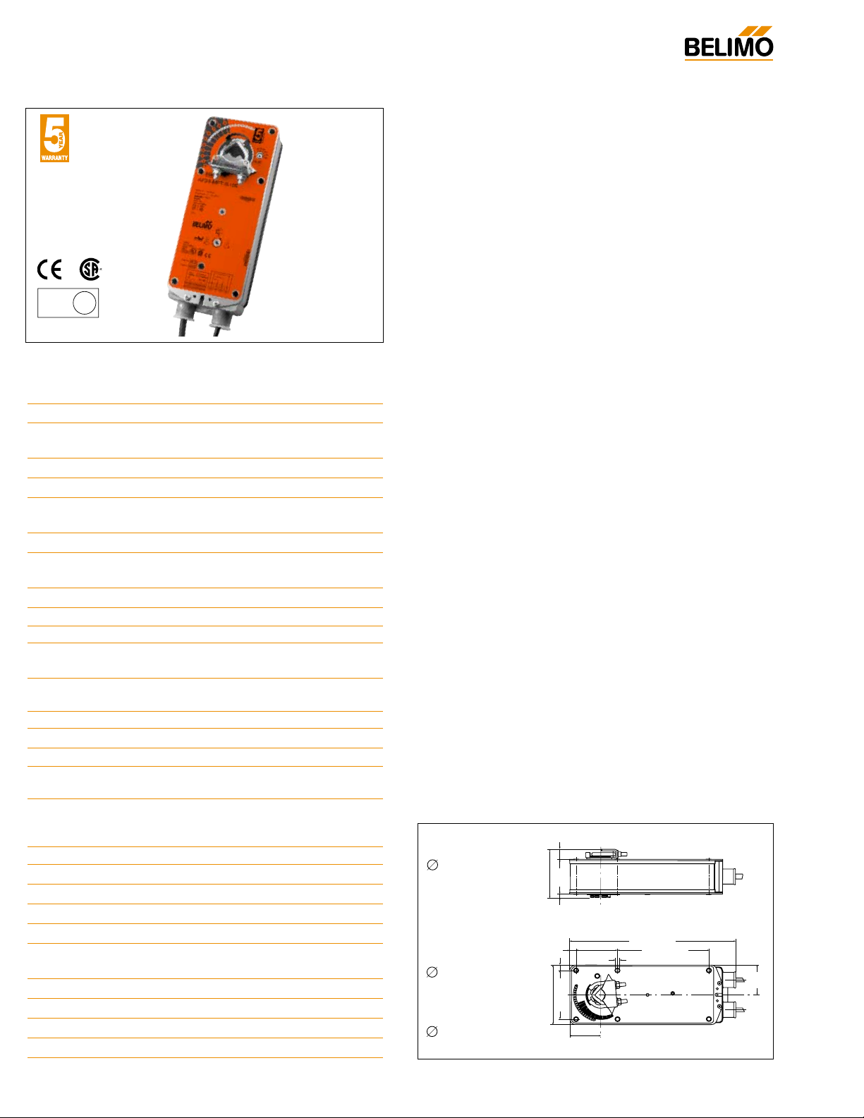
D001
AF24-MFT95 US
Proportional damper actuator, Spring Return Fail-Safe, 24 V for use with
Honeywell
®
electronic Series 90, or a 0 to 135Ω input
Technical Data AF24-MFT95 US
Power supply 24 VAC ± 20% 50/60 Hz
24 VDC ± 10%
Power consumption running: 6 W ; holding: 2 W
Transformer sizing 10 VA (class 2 power source)
Electrical connection 3 ft, 18 GA appliance cable
1/2” conduit connector
Overload protection electronic throughout 0 to 95° rotation
Operating range WRB 0 to 135Ω Honeywell electronic series
90, or a 0 to 135 Ω input
Feedback output U* 2 to 10 VDC, 0.5 mA max
Mech. angle of rotation* 95°, adjustable 35° to 95° w/ZDB-AF2
Torque 133 in-lb [15 Nm] constant
Direction of rotation* spring: reversible with cw/ccw mounting
motor: reversible with built-in switch
Position indication visual indicator, 0° to 95° (0° is spring
return position)
Manual override 3mm hex crank (shipped w/actuator)
Running time motor* 150 seconds constant
Running time spring <20 sec spring return fail safe position
Angle of Rotation Off (Default)
Adaptation*
Override control* Min. (Min Position) = 0%
- ZS
(Mid. Position) = 50%
- Max. (Max. Position) = 100%
Humidity 5 to 95% RH non-condensing
Ambient temperature -22°F to +122°F [-30°C to +50°C]
Storage temperature -40°F to +176°F [-40°C to +80°C]
Housing NEMA type 2 / IP54
Housing material zinc coated metal
Agency listings UL 873 listed, CE, CSA C22.2
No. 24 certified
Noise level max. 45 dB (A)
Servicing maintenance free
Quality standard ISO 9001
Weight 6.0 lbs (2.7 kg.)
* Variable when configured with MFT options
AF24-MFT95 US
Dimensions [All numbers in brackets are in millimeters.]
• Torque min. 133 in-lb
• Control fixed, 0 to 135Ω input, or Honeywell series 90 (fixed)
• Feedback 2 to 10 VDC (DEFAULT)
Application
For proportional modulation of dampers and control valves in
HVAC systems. The AF24-MFT95 US provides mechanical
spring return operation for reliable fail-safe application.
Default/Configuration
Default parameters for 0 to 135Ω Input applications of the
AF24-MFT95 US actuator are assigned during manufacturing.
If required, custom versions of the actuator can be ordered.
However the control input cannot be modified via MFT-Handy tool
or PC-software. The parameters noted in the Technical Data
table are variable.
These parameters can be changed by three means:
• Pre-set configurations from Belimo
• Custom configurations from Belimo
• Configurations set by the customer using the MFT-Handy
®
or the MFT-Actuate™ PC software application.
Operation
The AF24-MFT95 US actuator provides 95° of rotation and is provided with a graduated position indicator showing 0° to 95°. The
actuator will synchronize the 0° mechanical stop or the physical
damper or valve mechanical stop and use this point for its zero
position during normal control operations. A unique manual override allows the setting of any actuator position within its 95° of
rotation with no power applied.This mechanism can be released
physically by the use of a crank supplied with the actuator. When
power is applied the manual override is released and the actuator
drives toward the fail-safe position.
The actuator uses a brushless DC motor which is controlled by an
Application Specific Integrated Circuit (ASIC) and a microprocessor. The microprocessor provides the intelligence to the ASIC to
provide a constant rotation rate and to know the actuator’s exact
position. The ASIC monitors and controls the brushless DC
motor’s rotation and provides a Digital Rotation Sensing (DRS)
function to prevent damage to the actuator in a stall condition.
The position feedback signal is generated without the need for
mechanical feedback potentiometers using DRS. The actuator
may be stalled anywhere in its normal rotation without the need of
mechanical end switches.
The AF24-MFT95 US is mounted directly to control shafts up to
1.05" diameter by means of its universal clamp and anti-rotation
bracket. A crankarm and several mounting brackets are available
for damper applications where the actuator cannot be direct coupled to the damper shaft. The spring return system provides minimum specified torque to the application during a power interruption. The AF24-MFT95 US actuator is shipped at +5° (5° from full
fail-safe) to provide automatic compression against damper gaskets for tight shut-off.
(Not selectable via MFT)
LISTED
94D5
TEMP. IND &
REG. EQUIP.
U
L
K4-2 US (supplied)
1/2" Centered
(Default)
3/4" Centered
(Field Selectable)
1.05" Centered
(Field Selectable)
K4-1 US (optional)
3/4" to 1.05"
Adjustable
K4 US (optional)
3/8" to 3/4"
Adjustable
0.65" [16.5]
3.10" [78]
0.19" [5]
0.39" [10]
0.35" [9]
3.86" [98]
[57]
2.24"
3.15" [80]
1.97"
[50]
2.64"
[67]
10.59" [269]
5.85" [148.5]
0.26" [6.5]
®
[49]
1.93"
Page 2
31
I20618 - Subject to change. © Belimo Aircontrols (USA), Inc.
AF
AF24-MFT95 US
Proportional damper actuator, Spring Return Fail-Safe, 24 V for use with
Honeywell
®
electronic Series 90, or a 0 to 135Ω input
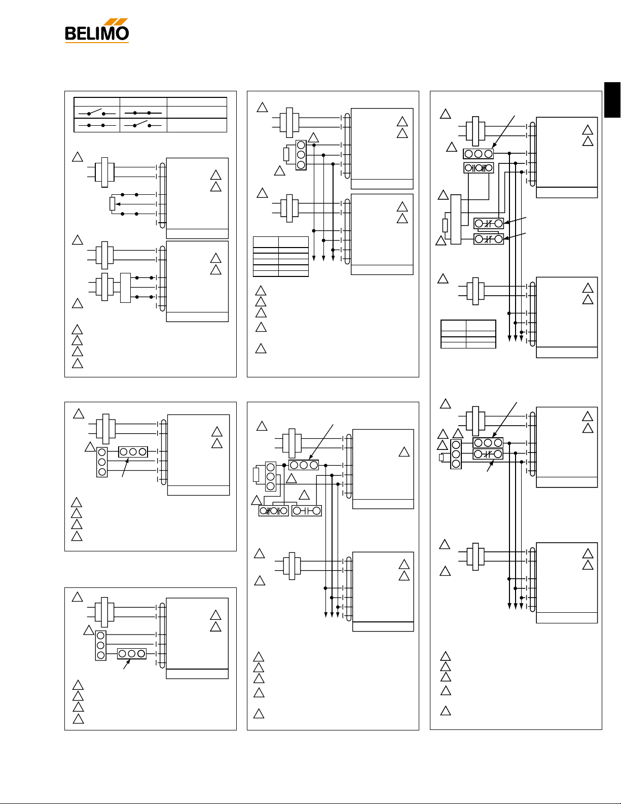
1
2
3
5
2
4
1 Common, Blk
2 + Hot, Red
3 W, Wht
4 R, Wht
5 B, Wht
6 ‘U5’
Output 2-10 VDC
AF24-MFT95 US
Line
Volts
24 VAC
Transformer
1
3
3
5
1 Common, Blk
2 + Hot, Red
3 W, Wht
4 R, Wht
5 B, Wht
6 ‘U5’
Output 2-10 VDC
AF24-MFT95 US
W
W
RR
Y
B
To other
actuators
Resistor Kit No. ZG-R06
Q209A
Minimum Position
Potentiometer
H205
Changeover
Controller
W973, W7100
Controller
Occupied
Contact
Honeywell T675A
Morning Warmup
Shunting
Resistor
Line
Volts
2
1
3
5
1 Common, Blk
2 + Hot, Red
3 W, Wht
4 R, Wht
5 B, Wht
6 ‘U5’
Output 2-10 VDC
AF24-MFT95 US
To other
actuators
Line
Volts
No. of
actuators Resistance
2 1300Ω
3 910Ω
4 768Ω
BR
W
W
R
B
1
3
2
5
4
1 Common, Blk
2 + Hot, Red
3 W, Wht
4 R, Wht
5 B, Wht
6 ‘U5’
Output 2-10 VDC
AF24-MFT95 US
Line
Volts
24 VAC
Transformer
Honeywell Q209A
Minimum Position
Potentiometer
Shunting
Resistor
RRB
W
W
W
R
B
Used with the W973 and W7100 controllers.
Honeywell
T675A Morning
Warmup
W973, W7100
T775
Override of AF24-MFT95 US
1
3
5
4
2
1 Common, Blk
2 + Hot, Red
3 W, Wht
4 R, Wht
5 B, Wht
6 ‘U5’
Output 2-10 VDC
AF24-MFT95 US
Line
Volts
24 VAC Transformer
1
1
2
3
3
5
5
4
1 Common, Blk
2 + Hot, Red
3 W, Wht
4 R, Wht
5 B, Wht
6 ‘U5’
Output 2-10 VDC
AF24-MFT95 US
W
R
B
To other
actuators
Resistor Kit No. ZG-R03
Series 90
Controller
Shunting
Resistor
Line
Volts
Provide overload protection and disconnect as required.
Actuators and controller must have separate transformers.
Consult controller instruction data for more detailed
installation information.
Resistor value depends on the type of controller and
the number of actuators. No resistor is used for one
actuator. Honeywell resistor kits may also be used.
To reverse control rotation, use the reversing switch.
No. of
actuators Resistance
2 140Ω
3 71.5Ω
4 47.5Ω
5 37.5Ω
6 28Ω
Switch A Switch B Damper Position
Damper Open
Damper Closed
The direction of rotation switch is set so that the fail safe position and the
position of the damper is closed with no signal at wire R.
1
3
4
1 Common, Blk
2 + Hot, Red
3 W, Wht
4 R, Wht
5 B, Wht
6 ‘U5’ Output 2-10 VDC
AF24-MFT95 US
A
B
Line
Volts
24 VAC Transformer
135Ω
1
1
2
2
3
3
4
4
1 Common, Blk
2 + Hot, Red
3 W, Wht
4 R, Wht
5 B, Wht
6 ‘U5’
Output 2-10 VDC
AF24-MFT95 US
A
W
R
B
Controller
B
Line
Volts
Line
Volts
24 VAC Transformer
Provide overload protection and disconnect as required.
Actuators and controller must have separate transformers.
Consult controller instruction data for more detailed
installation information.
To reverse control rotation, use the reversing switch.
1
3
2
2
5
4
1 Common, Blk
2 + Hot, Red
3 W, Wht
4 R, Wht
5 B, Wht
6 ‘U5’
Output 2-10 VDC
AF24-MFT95 US
Line
Volts
24 VAC
Transformer
1
1
2
3
3
5
5
4
1 Common, Blk
2 + Hot, Red
3 W, Wht
4 R, Wht
5 B, Wht
6 ‘U5’
Output 2-10 VDC
AF24-MFT95 US
To other
actuators
Series 90
Controller
S963A
Minimum Position
Potentiometer
H205 Changeover Controller
Occupied
Contact
Shunting
Resistor
Line
Volts
Provide overload protection and disconnect as required.
Actuators and controller must have separate transformers.
Consult controller instruction data for more detailed
installation information.
Resistor value depends on the type of controller and
the number of actuators. No resistor is used for one
actuator. Honeywell resistor kits may also be used.
To reverse control rotation, use the reversing switch.
RB
W
B
R
W
W
R
B
Wiring multiple actuators to a Series 90
controller using a minimum position
potentiometer.
1
2
3
4
1 Common, Blk
2 + Hot, Red
3 W, Wht
4 R, Wht
5 B, Wht
6 ‘U5’
Output 2-10 VDC
AF24-MFT95 US
Line
Volts
24 VAC Transformer
WBR
W
B
R
R
Series 90 low limit control
135Ω for 0 to 50% control
280Ω for 0 to 100% control
Series 90
Controller
1
2
3
4
Provide overload protection and disconnect as required.
Actuators and controller must have separate transformers.
Consult controller instruction data for more detailed
installation information.
To reverse control rotation, use the reversing switch.
AF24-MFT95 USused with a Series 90 controller and a Series 90 low limit control
1
2
3
4
1 Common, Blk
2 + Hot, Red
3 W, Wht
4 R, Wht
5 B, Wht
6 ‘U5’
Output 2-10 VDC
AF24-MFT95 US
Line
Volts
24 VAC Transformer
W B
W
B
R
R
Series 90 high limit control - 280Ω
Series 90
Controller
1
2
3
4
Provide overload protection and disconnect as required.
Actuators and controller must have separate transformers.
Consult controller instruction data for more detailed
installation information.
To reverse control rotation, use the reversing switch.
AF24-MFT95 USused with a Series 90 controller and a Series 90 high limit control
Typical wiring diagrams for multiple
actuators used with the W973, W7100
and T775 controllers.
Proportional Potentiometric Control
Wiring multiple actuators to a Series 90
controller.
W015
W018
W020
W016
W019
W017
®
Provide overload protection and disconnect as required.
1
Actuators and controller must have separate transformers.
2
Consult controller instruction data for more detailed
3
installation information.
Resistor value depends on the type of controller and
4
the number of actuators. No resistor is used for one
actuator. Honeywell resistor kits may also be used.
5
To reverse control rotation, use the reversing switch.
 Loading...