

Page 1
DriveIT Low Voltage AC Drives
User’s Manual
ACH550-UH HVAC Drives (1
…150 Hp)
Page 2

2 ACH550-UH User’s Manual
ACH550 Drive Manuals
GENERAL MANUALS
ACH550-UH HVAC User's Manual (1…150 HP)
• Safety
•Installation
• Start-Up
• Diagnostics
• Maintenance
• Technical Data
ACH550-UH Installation Supplement (200...550 HP)
• Safety
•Installation
• Maintenance
• Technical Data
ACH550 Input Disconnect and Bypass Supplement
(1...550 HP)
• Safety
•Installation
• Start-Up
• Maintenance
• Technical Data
BACnet is a registered trademark of ASHRAE.
CANopen is a registered trademark of CAN in Automation
e.V.
ControlNet is a registered trademark of ControlNet
International.
DeviceNet is a registered trademark of Open DeviceNet
Vendor Association.
DRIVECOM is a registered trademark of DRIVECOM User
Organization.
Ethernet is a registered trademark of Xerox Corp.
Interbus is a registered trademark of Interbus Club.
LonWorks is a registered trademark of Echelon Corp.
Metasys is a registered trademark of Johnson Controls Inc.
Modbus and Modbus Plus are registered trademarks of
Schneider Automation Inc.
Profibus is a registered trademark of Profibus Trade Org.
Profibus-DP is a registered trademark of Siemens AG.
OPTION MANUALS
(Fieldbus Adapters, I/O Extension Modules etc., manuals
delivered with optional equipment)
Relay Output Extension Module (typical title)
•Installation
• Programming
• Fault tracing
• Technical data
© 2004 ABB Oy. All Rights Reserved.
Page 3

ACH550-UH User’s Manual 3
Safety
Warning! The ACH550 adjustable speed AC drive should ONLY be installed by
a qualified electrician.
Warning! Even when the motor is stopped, dangerous volt age is present a t the
Power Circuit terminals U1, V1, W1 and U2, V2, W2 and, where present, UDC+,
UDC-, BRK+ and BRK-.
Warning! Dangerous voltage is present when input power is connected. After
disconnecting the supply , wait at least 5 minutes (to let the intermediate circuit
capacitors discharge) before removing the cover.
Warning! Even when power is removed from the input terminals of the
ACH550, there may be dangerous voltage (from external sources) on the
terminals of the relay outputs R01
Warning! When the control te rminals of two or mo re drive units are connected
in parallel, the auxiliary voltage for these control connections must be taken
from a single source which can either be one of the units or an external
supply.
…R03.
Warning! The ACH550-UH is not a field repairable unit. Never attempt to repair
a malfunctioning unit; contact the factory or your local Authorized Service
Center for replacement.
Warning! The ACH550 will start up automatically after an input voltage
interruption if the external run command is on.
Warning! The heat sink may reach a high temperature. See "Technical Data" on
page 225.
Warning! If the drive will be used in a floating network, remove screws at EM1
and EM3 (Frame size R1
diagrams on page 14 and page 15 respectively.
Note! For more technical information, contact the factory or your local ABB sales
representative.
…R4), or F1 and F2 (Frame size R5 or R6). See
Safety
Page 4

4 ACH550-UH User’s Manual
Use of Warnings and Notes
There are two types of safety instructions throughout this manual:
• Notes draw attention to a particular condition or fact, or give information on a
subject.
• Warnings caution you about conditions which can result in serious injury or death
and/or damage to the equipment. They also tell you how to avoid the danger . The
warning symbols are used as follows:
Dangerous voltage warning warns of high voltage which can cause physical
injury and/or damage to the equipment.
General warning warns about conditions, other than those caused by
electricity, which can result in physical injury and/or damage to the equipment
Safety
Page 5

ACH550-UH User’s Manual 5
Table of Contents
Safety
Use of Warnings and Notes . . . . . . . . . . . . . . . . . . . . . . . . . . . . . . . . . . . . . . . . 4
Table of Contents
Installation
Installation Flow Chart . . . . . . . . . . . . . . . . . . . . . . . . . . . . . . . . . . . . . . . . . . . . 7
Preparing for Installation . . . . . . . . . . . . . . . . . . . . . . . . . . . . . . . . . . . . . . . . . . 8
Installing the Drive . . . . . . . . . . . . . . . . . . . . . . . . . . . . . . . . . . . . . . . . . . . . . . 10
Start-Up
HVAC Control Panel Features . . . . . . . . . . . . . . . . . . . . . . . . . . . . . . . . . . . . . 22
Start-Up . . . . . . . . . . . . . . . . . . . . . . . . . . . . . . . . . . . . . . . . . . . . . . . . . . . . . . 23
Modes . . . . . . . . . . . . . . . . . . . . . . . . . . . . . . . . . . . . . . . . . . . . . . . . . . . . . . . . 25
Application Macros . . . . . . . . . . . . . . . . . . . . . . . . . . . . . . . . . . . . . . . . . . . . . . 35
Parameter Descriptions . . . . . . . . . . . . . . . . . . . . . . . . . . . . . . . . . . . . . . . . . . 51
Serial Communication – EFB
Overview . . . . . . . . . . . . . . . . . . . . . . . . . . . . . . . . . . . . . . . . . . . . . . . . . . . . 143
Planning . . . . . . . . . . . . . . . . . . . . . . . . . . . . . . . . . . . . . . . . . . . . . . . . . . . . . 144
Mechanical and Electrical Installation – EFB . . . . . . . . . . . . . . . . . . . . . . . . . 145
Communication Set-up – EFB . . . . . . . . . . . . . . . . . . . . . . . . . . . . . . . . . . . . 146
Activate Drive Control Functions – EFB . . . . . . . . . . . . . . . . . . . . . . . . . . . . . 147
Feedback from the Drive – EFB . . . . . . . . . . . . . . . . . . . . . . . . . . . . . . . . . . . 151
Diagnostics – EFB . . . . . . . . . . . . . . . . . . . . . . . . . . . . . . . . . . . . . . . . . . . . . 153
Modbus Protocol Technical Data . . . . . . . . . . . . . . . . . . . . . . . . . . . . . . . . . . 155
ABB Drives Profile Technical Data . . . . . . . . . . . . . . . . . . . . . . . . . . . . . . . . . 162
N2 Protocol Technical Data . . . . . . . . . . . . . . . . . . . . . . . . . . . . . . . . . . . . . . 170
FLN Protocol Technical Data . . . . . . . . . . . . . . . . . . . . . . . . . . . . . . . . . . . . . 179
BACnet Technical Data . . . . . . . . . . . . . . . . . . . . . . . . . . . . . . . . . . . . . . . . . 192
Serial Communication – FBA
Overview . . . . . . . . . . . . . . . . . . . . . . . . . . . . . . . . . . . . . . . . . . . . . . . . . . . . 193
Planning . . . . . . . . . . . . . . . . . . . . . . . . . . . . . . . . . . . . . . . . . . . . . . . . . . . . . 195
Mechanical and Electrical Installation – FBA . . . . . . . . . . . . . . . . . . . . . . . . . 196
Communication Set-up – FBA . . . . . . . . . . . . . . . . . . . . . . . . . . . . . . . . . . . . 197
Activate Drive Control Functions – FBA . . . . . . . . . . . . . . . . . . . . . . . . . . . . . 197
Feedback from the Drive – FBA . . . . . . . . . . . . . . . . . . . . . . . . . . . . . . . . . . . 200
Diagnostics – FBA . . . . . . . . . . . . . . . . . . . . . . . . . . . . . . . . . . . . . . . . . . . . . 201
ABB Drives Profile Technical Data . . . . . . . . . . . . . . . . . . . . . . . . . . . . . . . . . 203
Generic Profile Technical Data . . . . . . . . . . . . . . . . . . . . . . . . . . . . . . . . . . . . 210
Diagnostics
Diagnostic Displays . . . . . . . . . . . . . . . . . . . . . . . . . . . . . . . . . . . . . . . . . . . . 212
Table of Contents
Page 6

6 ACH550-UH User’s Manual
Correcting Faults . . . . . . . . . . . . . . . . . . . . . . . . . . . . . . . . . . . . . . . . . . . . . . 213
Correcting Alarms . . . . . . . . . . . . . . . . . . . . . . . . . . . . . . . . . . . . . . . . . . . . . . 218
Maintenance
Maintenance Intervals . . . . . . . . . . . . . . . . . . . . . . . . . . . . . . . . . . . . . . . . . . . 221
Heatsink . . . . . . . . . . . . . . . . . . . . . . . . . . . . . . . . . . . . . . . . . . . . . . . . . . . . . 221
Main Fan Replacement . . . . . . . . . . . . . . . . . . . . . . . . . . . . . . . . . . . . . . . . . . 222
Internal Enclosure Fan Replacement . . . . . . . . . . . . . . . . . . . . . . . . . . . . . . . 223
Capacitors . . . . . . . . . . . . . . . . . . . . . . . . . . . . . . . . . . . . . . . . . . . . . . . . . . . . 223
Control Panel . . . . . . . . . . . . . . . . . . . . . . . . . . . . . . . . . . . . . . . . . . . . . . . . . 224
Technical Data
Ratings . . . . . . . . . . . . . . . . . . . . . . . . . . . . . . . . . . . . . . . . . . . . . . . . . . . . . . 225
Input Power Connections . . . . . . . . . . . . . . . . . . . . . . . . . . . . . . . . . . . . . . . . 228
Motor Connections . . . . . . . . . . . . . . . . . . . . . . . . . . . . . . . . . . . . . . . . . . . . . 232
Control Connections . . . . . . . . . . . . . . . . . . . . . . . . . . . . . . . . . . . . . . . . . . . . 237
Efficiency . . . . . . . . . . . . . . . . . . . . . . . . . . . . . . . . . . . . . . . . . . . . . . . . . . . . 240
Cooling . . . . . . . . . . . . . . . . . . . . . . . . . . . . . . . . . . . . . . . . . . . . . . . . . . . . . . 240
Dimensions and Weights . . . . . . . . . . . . . . . . . . . . . . . . . . . . . . . . . . . . . . . . 241
Degrees of Protection . . . . . . . . . . . . . . . . . . . . . . . . . . . . . . . . . . . . . . . . . . . 244
Ambient Conditions . . . . . . . . . . . . . . . . . . . . . . . . . . . . . . . . . . . . . . . . . . . . . 244
Materials . . . . . . . . . . . . . . . . . . . . . . . . . . . . . . . . . . . . . . . . . . . . . . . . . . . . . 245
Applicable Standards . . . . . . . . . . . . . . . . . . . . . . . . . . . . . . . . . . . . . . . . . . . 245
Liability Limits . . . . . . . . . . . . . . . . . . . . . . . . . . . . . . . . . . . . . . . . . . . . . . . . . 247
Index
Table of Contents
Page 7
ACH550-UH User’s Manual 7
Installation
Study these inst allation instructio ns carefully before proceeding. Failure to observe
the warnings and instructions may cause a malfunction or personal hazard.
Warning! Before you begin read "Safety" on page 3.
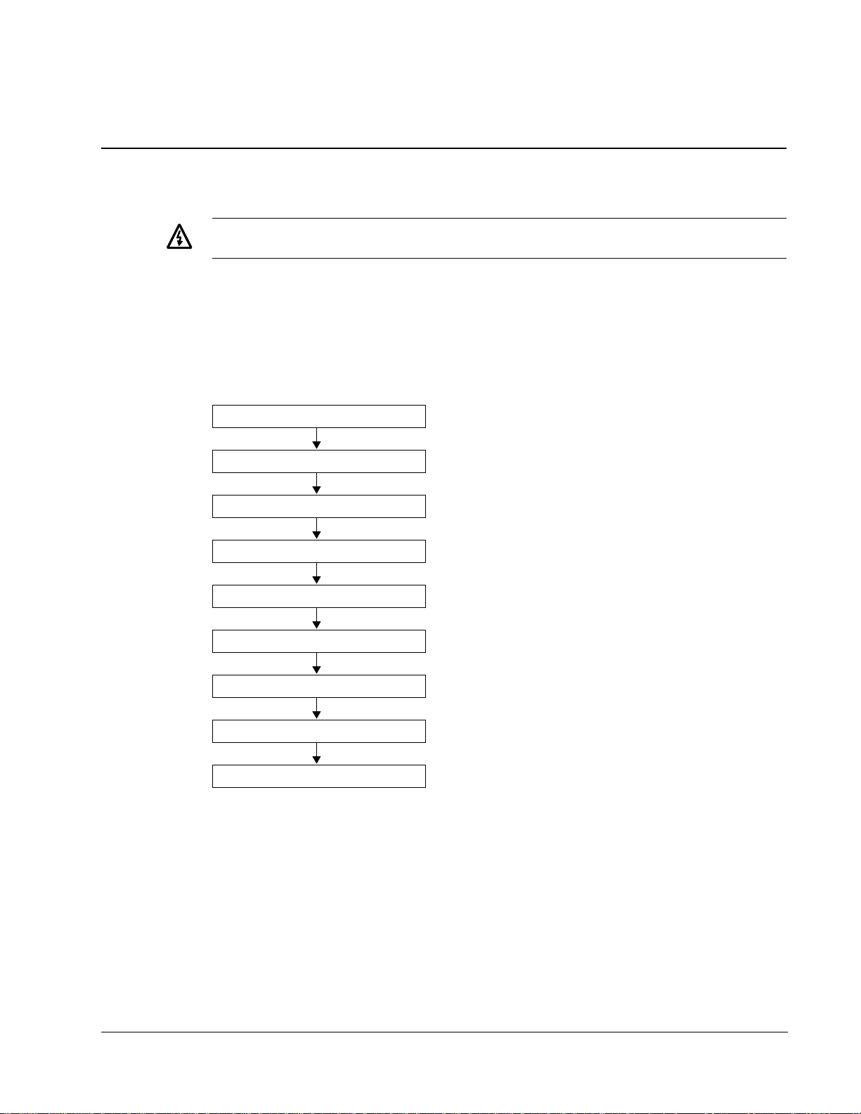
Installation Flow Chart
The installation of the ACH550 adjustable speed AC drive follows the outline below.
The steps must be carried out in the order shown. At the right of each step are
references to the detailed information needed for the correct installation of the unit.
Task See
PREPARE for installation "Preparing for Installation" on page 8.
PREPARE the Mounting Location "Prepare the Mounting Location" on page 11.
REMOVE the front cover "Remove Front Cover" on page 11.
MOUNT the drive "Mount the Drive" on page 12.
INSTALL wiring "Install the Wiring" on page 12.
CHECK installation "Check Installation" on page 18.
RE-INSTALL the cover "Re-install Cover" on page 18.
APPLY power "Apply Power" on page 19.
START-UP "Start-Up" on page 20.
Installation
Page 8
8 ACH550-UH User’s Manual
Preparing for Installation
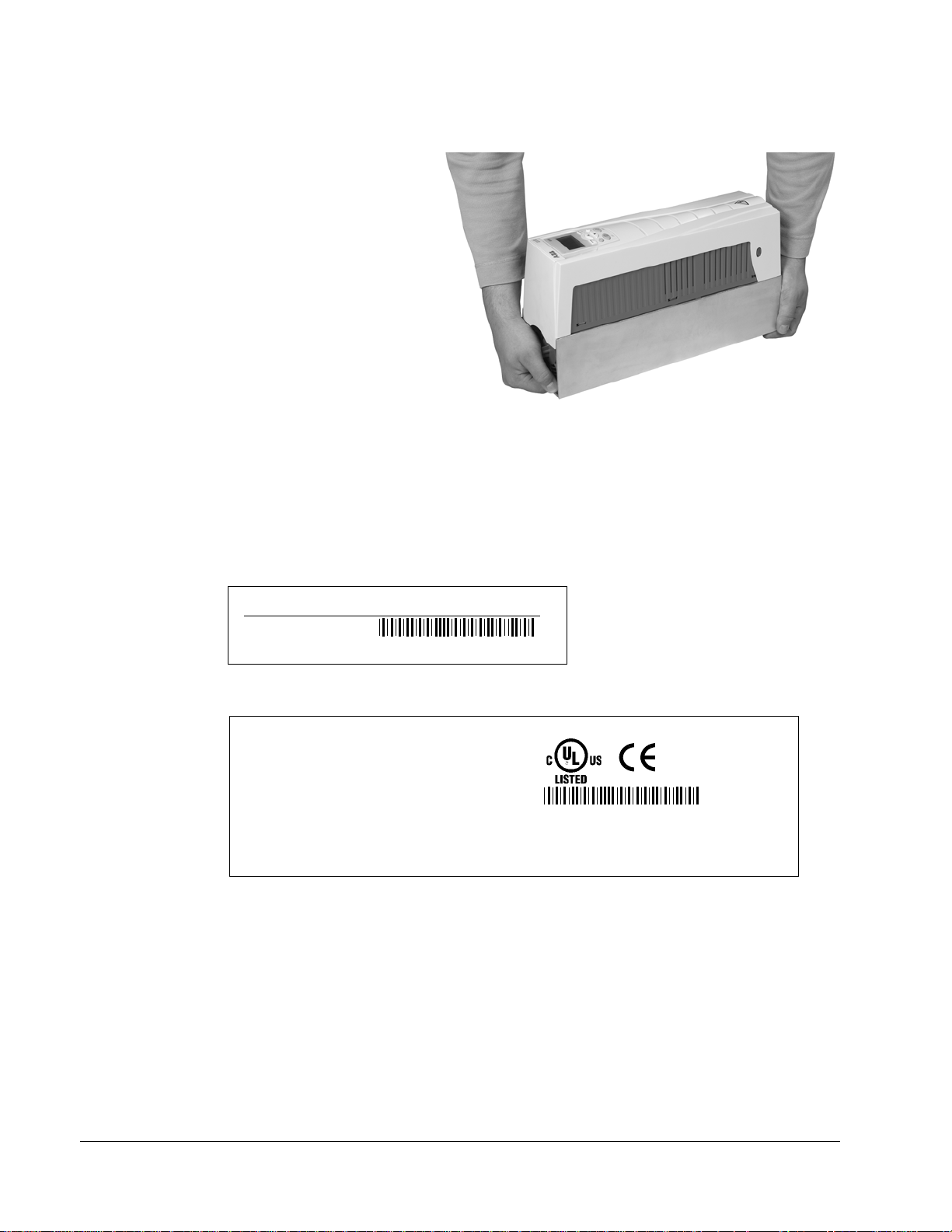
Lifting the Drive
Lift the drive only by the metal
chassis.
Unpack the Drive
1. Unpack the drive.
2. Check for any damage and
notify the shipper immediately
if damaged components are
found.
3. Check the contents against
the order and the shipping label to verify that all parts have been received.
Drive Identification
Drive Labels
IP2040
To determine the type of drive you are installing, refer to either:
• Serial number label attached on upper part of the chokeplate between the
mounting holes.
ACH550-UH-08A8-4
U1
I2N
PN
3~ 380...480 V
8.8 A
4
Ser. no.
*2030700001*
• Type code label attached on the heat sink – on the right side of the unit cover.
Input U1
Output U2
I2N
f2
Motor PN
ACH550-UH-08A8-4
I1N
f1
3~ 380...480 V
8.8 A
48...63 Hz
3~ 0...U
8.8 A
0...500 Hz
4
V
1
Ser. no.
*2030700001*
Installation
Page 9

ACH550-UH User’s Manual 9
Type Code
Use the following chart to interpret the type code found on either label.
ACH550-UH-08A8-4+...
AC, HVAC Drive – 550 product series
Construction (region specific)
01 = Setup and parts specific to IEC installation and compliance
UH = Setup and parts specific to US installation and NEMA compliance
Output current rating
See Ratings chart for details
Voltage rating
2 = 208…240 VAC
4 = 380…480 VAC
Enclosure protection class
No specification = IP 21 / UL type 1
B055 = IP 54 / UL type 12
Ratings and Frame Size
The chart in "Ratings" on page 225 lists technical specifications, and identifies the
drive’s frame size – significant, since some instructions in this document, vary,
depending on the drive’s frame size. To read the Ratings table, you need the “Output
current rating” entry from the type code (see above). Also, when using the Ratings
tables, note that there are two tables based on the drive’s “Voltage rating”.
Motor Compatibility
The motor, drive, and supply power must be compatible:
Motor
Specification
Motor type 3-phase induction motor –
Nominal current Motor value is within this
range: 0.15…1.5 * I
(I
2N
Nominal frequency 10…500 Hz –
Voltage range Motor is compatible with
the ACH550 voltage range.
Verify Reference
• Type code label on drive, entry for Output I2N,
= normal use current)
2N
or
• Type code on drive and rating table in
"Technical Data" on page 225.
208…240 V (for ACH550-UH-XXXX-2) or
380…480 V (for ACH550-UH-XXXX-4)
Tools Required
To install the ACH550 you need the following:
• Screwdrivers (as appropriate for the mounting hardware used)
• Wire stripper
• Tape measure
•Drill
Installation
Page 10

10 ACH550-UH User’s Manual
• Frame Size R5 or R6 with IP 54 / UL type 12 enclosure: Punch for conduit
mounting holes
• Mounting hardware: screws or nuts and bolts, four each. The type of hardware
depends on the mounting surface and the frame size:
Frame Size Mounting Hardware
R1…R4 M5 #10
R5 M6
R6 M8 5/16 in
1/4 in
Suitable Environment and Enclosure
Confirm that the site meets the environmental requirements. To prevent damage
prior to installation, store and transport the drive according to the environmental
requirements specified for storage and transportation. See "Ambient Conditions"
244.
page
on
Confirm that the enclosure is appropriate, based on the site contamination level:
• IP 21 / UL type 1 enclosure. The site must be free of airborne dust, corrosive
gases or liquids, and conductive contaminants such as condensation, carbon
dust, and metallic particles.
• IP 54 / UL type 12 enclosure. This enclosure provides protection from airborne
dust and light sprays or splashing water from all directions.
Suitable Mounting Location
Confirm that the mounting location meets the following constraints:
• The drive must be mounted vertically on a smooth, solid surface, and in a suitable
environment as defined above.
• The minimum space requirements for the drive are the outside dimensions (see
"Outside Dimensions" on page 243), plus air flow space around the unit (see
"Cooling" on page 240).
• The distance between the motor and the drive is limited by the maximum motor
cable length. See either
"EN61800-3 Compliant Motor Cables" on page 235.
• The mounting site must support the drive’s modest weight. See "Weight" on p age
242.
Installing the Drive
Warning! Before installing the ACH550, ensure the input power supply to the
drive is off.
"Motor Connection Specifications" on page 232, or
Installation
Page 11
ACH550-UH User’s Manual 11
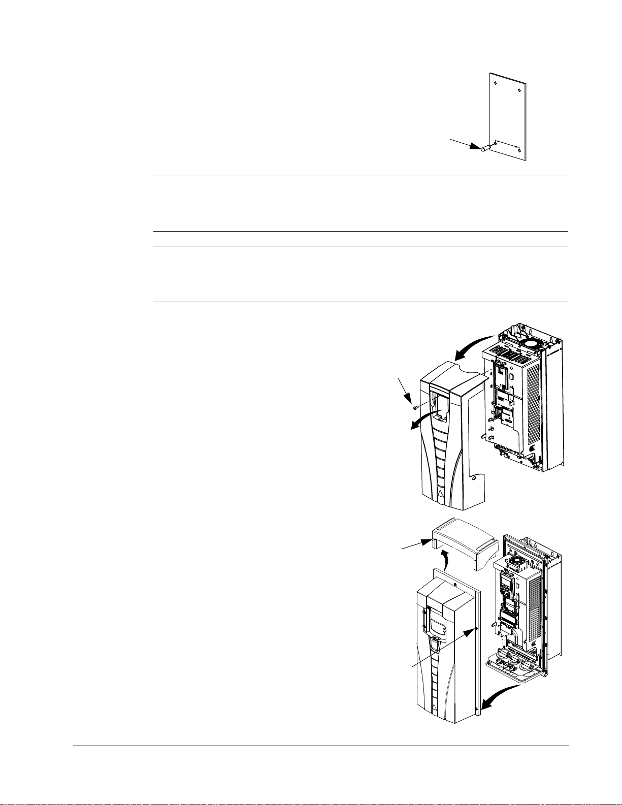
Prepare the Mounting Location
The ACH550 should only be mounted where all of the
requirements defined in "Prepa ring for Installation" on
page 8 are met.
1. Mark the position of the mounting holes.
1
2. Drill holes of appropriate size.
Note! Frame sizes R3 and R4 have four holes along the top. Use only two. If
possible, use the two outside holes (to allow room to remove the fan for
maintenance).
Note! ACH400 drives can be replaced using the original mounting holes. For R1 and
R2 frame sizes, the mounting holes are identical. For R3 and R4 frame sizes, the
inside mounting holes on the top of ACH550 drives match ACH400 mounts.
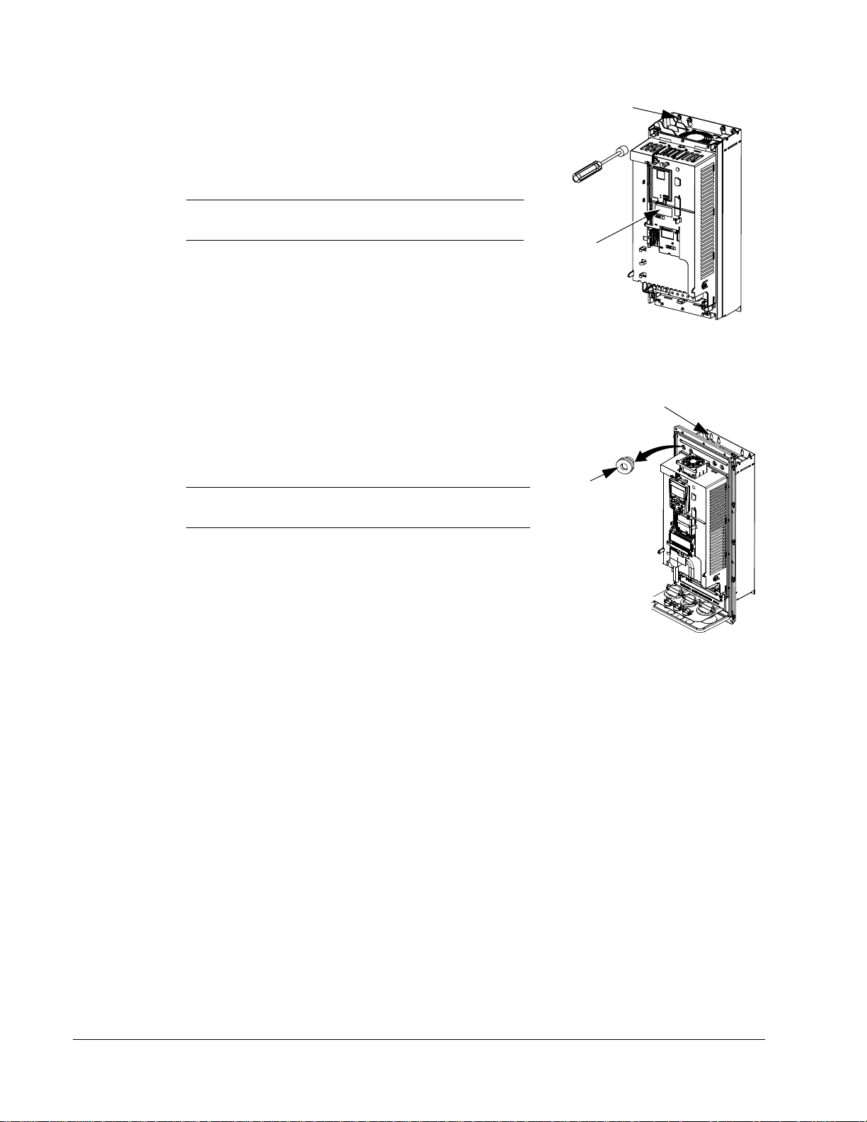
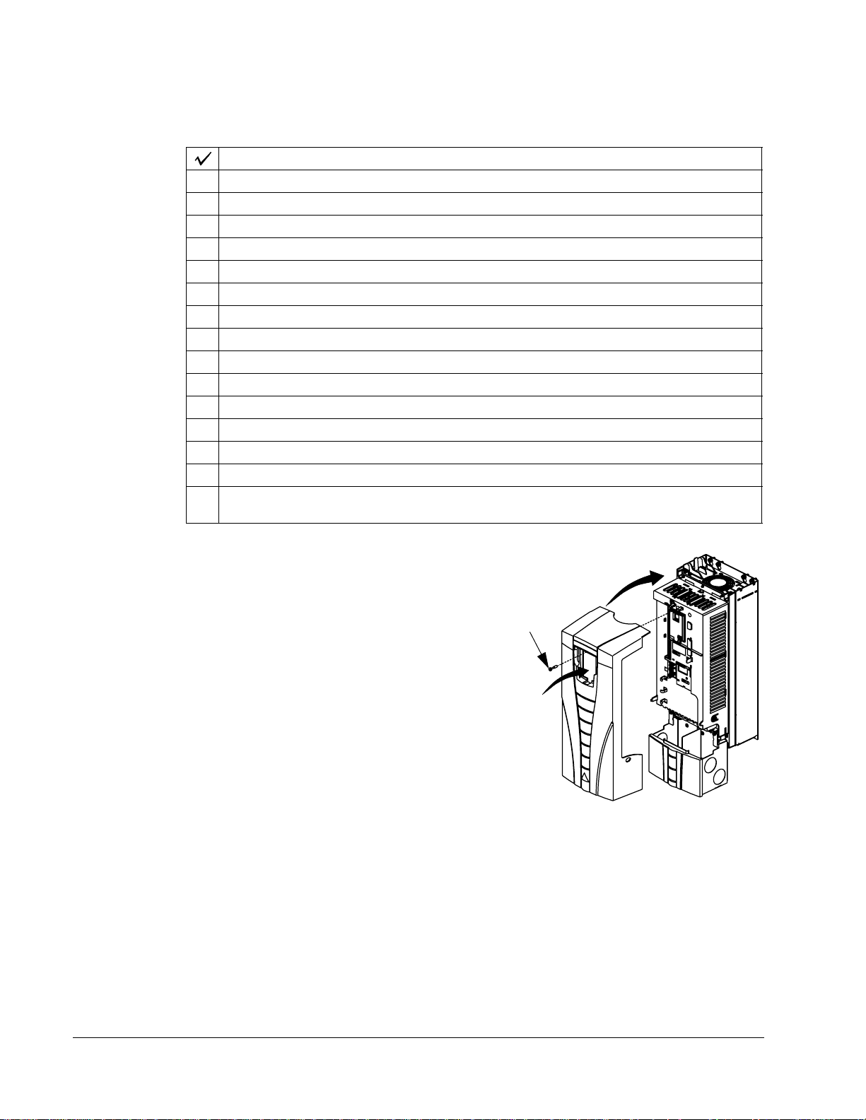
Remove Front Cover
IP 21 / UL Type 1
3
1. Remove the control panel, if attached.
2
2. Loosen the captive screw at the top.
3. Pull near the top to remove the cover.
X0002
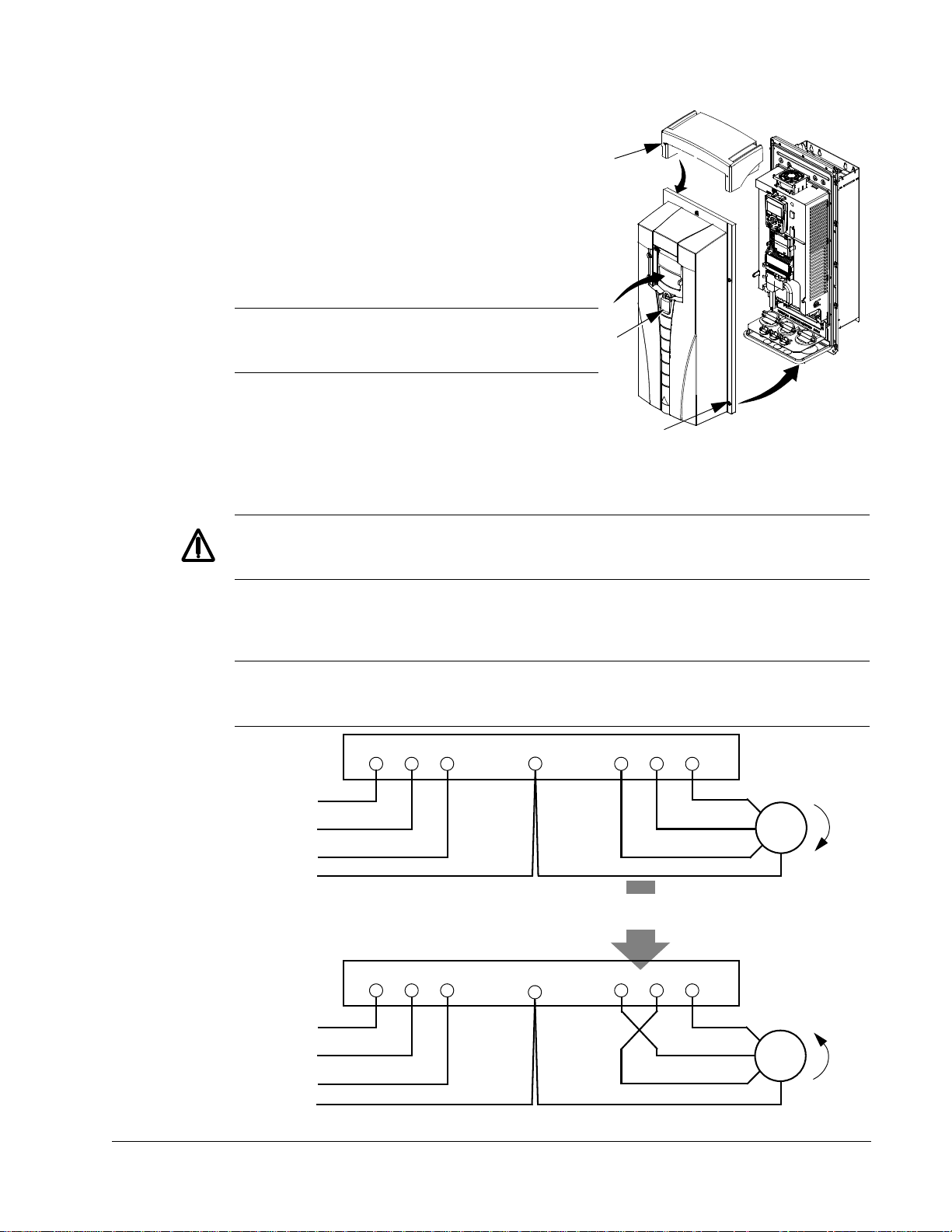
IP 54 / UL Type 12
1. If hood is present: Remove screws (2) holding
the hood in place.
2. If hood is present: Slide hood up and off of the
cover.
3. Loosen the captive screws around the edge of
the cover.
4. Remove the cover.
1
IP2000
1
2
3
4
FM
Installation
Page 12
12 ACH550-UH User’s Manual
Mount the Drive
1
IP 21 / UL Type 1
1. Position the ACH550 onto the mounting screws
or bolts and securely tighten in all four corners.
Note! Lift the ACH550 by its metal chassis.
2
2. Non-English speaking locations: Add a warning
sticker in the appropriate language over the
existing warning on the top of the module.
IP 54 / UL Type 12
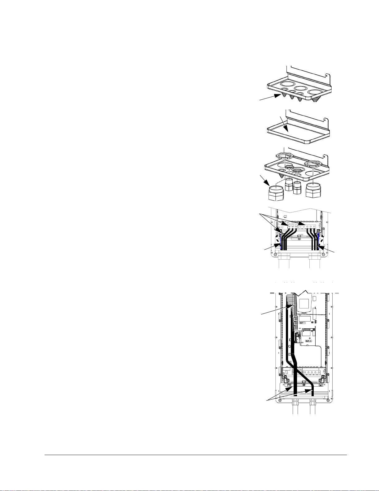
For the IP54 / UL Type 12 enclosures, rubber plugs are required in the holes
provided for access to the drive mounting slots.
1. As required for access, remove the rubber plugs.
Push plugs out from the back of the drive.
2. Position the ACH550 onto the mounting screws
or bolts and securely tighten in all four corners.
1, 3
Note! Lift the ACH550 by its metal chassis.
IP2002
2
3. Re-install the rubber plugs.
4. Non-English speaking locations: Add a warning
sticker in the appropriate language over the
existing warning on the top of the module.
Install the Wiring
Conduit Kit
Wiring drives with the IP 21 / UL type 1 Enclosure requires a conduit kit with the
following items:
• conduit box
•screws
• cover
The kit is included with IP 21 / UL type 1 Enclosures.
FM
Installation
Page 13

ACH550-UH User’s Manual 13
Wiring Overview
Warning! Ensure the motor is compatible for use with the ACH550. The
ACH550 must be installed by a competent person in accordance with the
considerations defined in
"Preparing for Installation" on page 8. If in doubt,
contact your local ABB sales or service office.
As you install the wiring, observe the following:
• There are two sets of wiring instructions – one set for each enclosure type (IP 21
/ UL type and IP 54 / UL type 12). Be sure to select the appropriate procedure.
• For the power connection points on the drive see the "Connection Diagrams"
section below.
• Use separate conduit runs to keep these three classes of wiring apart:
– Input power wiring.
– Motor wiring.
– Control/communications wiring.
• For details on power connections, refer to the following sections in "Technical
Data":
– "Input Power Connections" on page 228.
– "Motor Connections" on page 232.
• For floating networks (also known as IT, ungrounded, or high impedance
networks):
– Disconnect the internal RFI filter by removing both the EM1 and EM3 screws
(frame sizes R1…R4, see page
14), or F1 and F2 screws (frame sizes
R5…R6, see page 15).
– Do NOT install an external filter, such as one of the kits listed in the filter table
236. Using an EMC/RFI filter grounds the input power through the filter
on
capacitors, which could be dangerous and could damage the unit.
– Where EMC requirements exist, check for excessive emission propagated to
neighboring low voltage networks. In some cases, the natural suppression in
transformers and cables is sufficient. If in doubt, use a supply transformer with
static screening between the primary and secondary windings.
• For details on control connections, refer to the following sections:
– "Control Connections" on page 237.
– "Application Macros" starting on page 35.
• For electro-magnetic compliance (EMC), follow local codes and the requirements
"Motor Cable Requirements for CE & C-Tick Compliance" on page 234. For
in
example:
– Properly ground the wire screen cable shields.
– Keep individual un-screened wires between the cable clamps and the screw
terminals as short as possible.
– Route control cables away from power cables.
Installation
Page 14
14 ACH550-UH User’s Manual
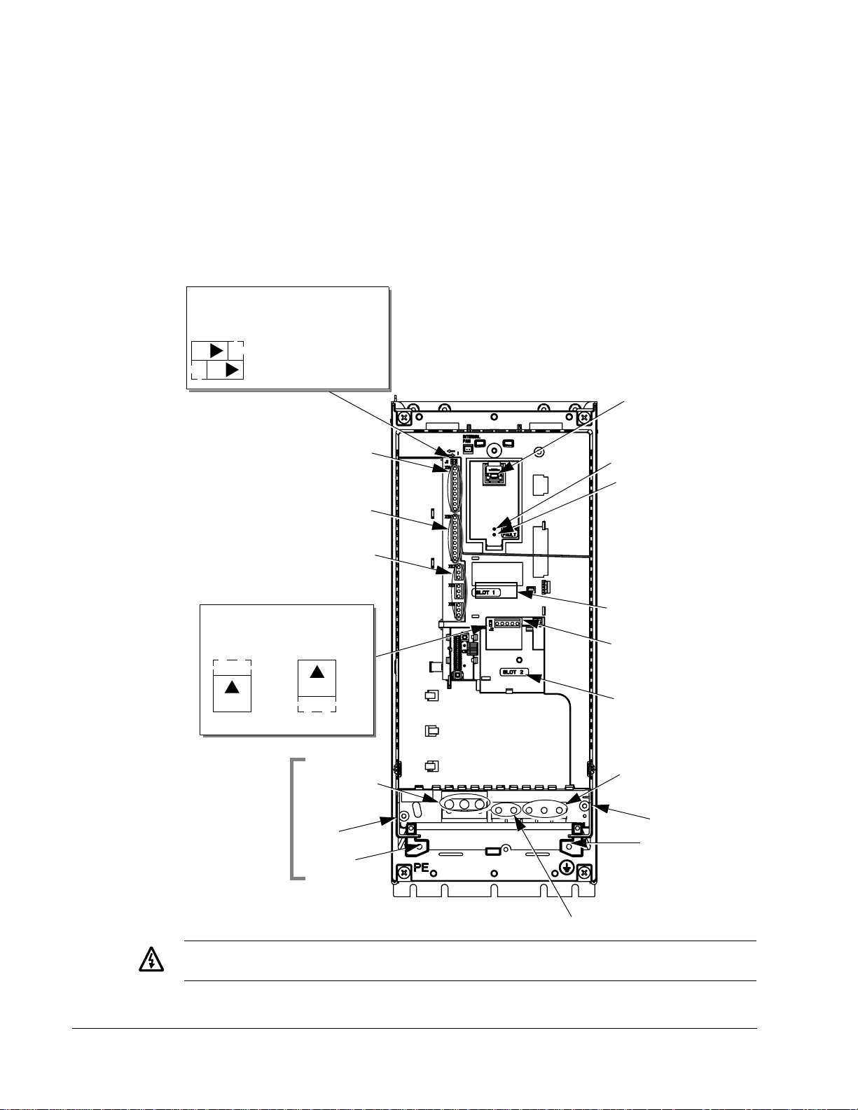
Connection Diagrams
The layout of connection terminals is similar for all frame sizes (R1…R6). The only
significant layout difference is in the power and ground terminals for frame sizes R5
and R6. The following diagrams show:
• Terminal layout for frame size R3, which, in general, applies to all frame sizes
except as noted above.
• Power and ground terminal layout for frame sizes R5 and R6.
R1…R4 (Diagram shows the R3 frame.)
J1 – DIP Switches
for Analog Inputs
J1
ON
X1 – Analog Inputs and Outputs
(and 10 V Ref. Voltage Output)
(and 24 V Aux. Voltage Output)
AI1: (in Voltage Position)
ON
AI2: (in Current Position)
X1 – Digital Inputs
Panel Connector
Power LED (Green)
Fault LED (Red)
X1 – Relay Outputs
J2 – DIP Switches
for RS485 Termination
J2
ON
off position on position
Frame Sizes
R5/R6 differ.
See next page.
J2
ON
Power Input
(U1, V1, W1)
EM1
Optional Module 1
X1 – Communications
(RS485)
Optional Module 2
Power Output to Motor
(U2, V2, W2)
EM3
GND
PE
X0003
Terminals Not Used
Installation
Warning! For floating (ungrounded) networks remove screws at EM1 and EM3.
Page 15
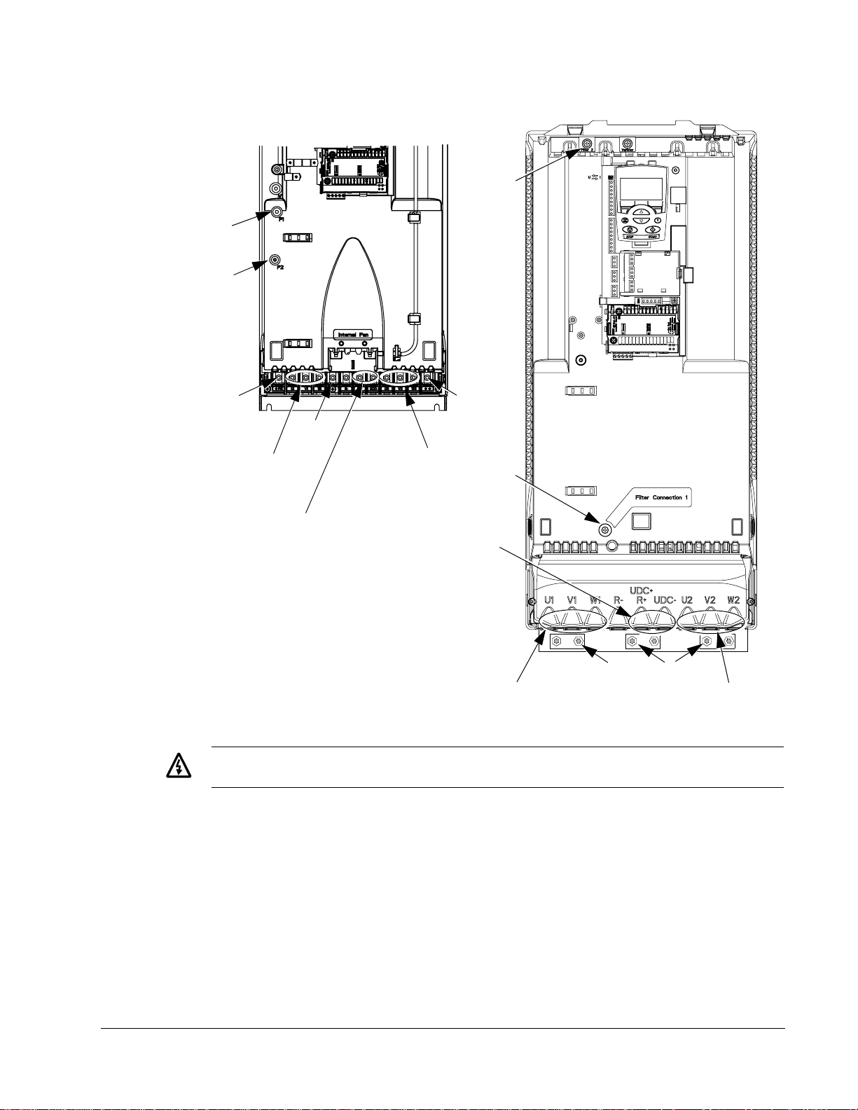
ACH550-UH User’s Manual 15
R5 R6
F2
F1
F2
PE
GND
X0011
GND
Power Input
(U1, V1, W1)
Power Output to Motor
(U2, V2, W2)
F1
Terminals Not Used
Terminals Not Used
X0013
Power Input
(U1, V1, W1)
PE
GND
Power Output to Motor
(U2, V2, W2)
Warning! For floating (ungrounded) networks remove screws at F1 and F2.
Installation
Page 16
16 ACH550-UH User’s Manual
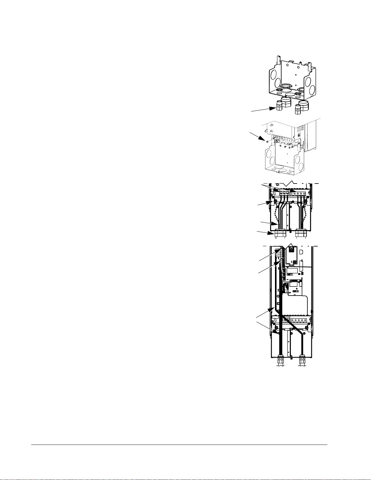
Wiring IP 21 / UL Type 1 Enclosure
1. Open the appropriate knockouts in the
conduit box. (See "Conduit Kit" above.)
2. Install thin-wall conduit clamps (not supplied).
3. Install conduit box.
4. Connect conduit runs for input power, motor
and control cables to the box.
5. Route input power and motor wiring through
separate conduits.
6. Strip wires.
7. Connect power, motor, and ground wires to
the drive terminals. See
"Wiring Overview" on
page 13.
8. Route the control cables through the conduit
(not the same conduit as either input power or
motor wiring).
9. Strip the control cable sheath ing and twist the
copper screen into a pig-tail.
2
3
7
7
5
4
10
12
X0007
X0005
IP2004
Installation
10. Connect the ground screen pig-tail for digital
and analog I/O cables at X1-1. (Ground only
at drive end.)
1 1. C onnect the ground screen pig -tail for RS485
cables at X1-28 or X1-32. (Ground only at
drive end.)
12. Strip and connect the individual control wires
to the drive terminals. See
"Wiring Overview"
on page 13.
13. Install the conduit box cover (1 screw).
8
IP2005
Page 17
ACH550-UH User’s Manual 17
Wiring IP 54 / UL Type 12 Enclosure
1. Step depends on Frame Size:
• Frame Sizes R1…R4: Remove and
discard the cable seals where conduit will
be installed. (The cable seals are coneshaped, rubber seals on the bottom of the
drive.)
IP50131
• Frame Sizes R4 and R5: Use punch to
create holes for conduit connections as
needed.
2. For each conduit run (input power, motor and
control wiring must be separate), install water
tight conduit connectors (not supplied).
3. Route the power wiring through conduit.
4. Route the motor wiring through conduit (not
the same conduit as input power wiring run).
5. Strip the wires.
6. Connect the power, motor, and ground wires
to the drive terminals. See
"Wiring Overview"
on page 13, and "Connection Diagrams" on
page 14.
7. Route the control cables through the conduit
(not the same conduit as either input power or
motor wiring runs).
1
IP5023
2
IP5006
6
3
4
IP5007
8. Strip the control cable sheathing and twist the
copper screen into a pig-tail.
9. Connect the ground screen pig-tail for digital
and analog I/O cables at X1-1. (Ground only
at drive end.)
10. Connect the ground screen pig-tail for RS485
cables at X1-28 or X1-32. (Ground only at
drive end.)
11. Strip and connect the individual control wires
to the drive terminals. See
"Wiring Overview"
on page 13.
12. Install the conduit box cover (1 screw).
9…1 1
7
IP5008
Installation
Page 18
18 ACH550-UH User’s Manual
Check Installation
Before applying power, perform the following checks.
Check
Installation environment conf orms to the drive’s specifications for ambient conditions.
The drive is mounted securely.
Space around the drive meets the drive’s specifications for cooling.
The motor and driven equipment are ready for start.
For floating networks: The internal RFI filter is disconnected.
The drive is properly grounded.
The input power voltage matches the drive nominal input voltage range.
The input power connections at U1, V1, and W1 are connected and tightened as specified.
The input power branch circuit protection is installed.
The motor connections at U2, V2, and W2 are connected and tightened as specified.
The input power, motor and control wiring are routed through separate conduit runs.
NO power factor compensation capacitors are in the motor cable.
The control connections are connected and tightened as specified.
NO tools or foreign objects (such as drill shavings) are inside the drive.
NO alternate power source for the motor (such as a bypass connection) is connected – no
voltage is applied to the output of the drive.
Re-install Cover
IP 21 / UL Type 1
1. Align the cover and slide it on.
2. Tighten the captive screw.
3. Re-install the control panel.
1
2
3
IP2009
Installation
Page 19
ACH550-UH User’s Manual 19
IP 54 / UL Type 12
1. Align the cover and slide it on.
4
2. Tighten the captive screws around the edge of
3
the cover.
3. Slide the hood down over the top of the cover.
4. Install the two screws that attach the hood.
5. Re-install the control panel.
5
Note! The control panel window must be
closed to comply with IP 54/UL type 12.
6
6. Optional: Add a lock (not supplied) to secure
the control panel window.
2
1
Apply Power
Always re-install the front cover before turning power on.
Warning! The ACH550 will start up automatically at power up, if the external
run command is on.
1. Apply input power.
When power is applied to the ACH550, the green LED comes on.
Note! Before increasing motor speed, check that the motor is running in the desired
direction.To change rotation direction, switch motor leads as shown below.
Drive
GND
Motor
Input
U1 V1 W1 U2 V2 W2
L1
L2
FM
Input
L3
GND
L1
L2
L3
GND
To change rotation direction,
switch motor leads
Drive
U1 V1 W1 U2 V2 W2
GND
Motor
FM
Installation
Page 20

20 ACH550-UH User’s Manual
Start-Up
The ACH550 has default parameter settings that are sufficient for many situations.
However, review the following situations. Perform the associated procedures as
appropriate.
Spin Motor
When first installed and started the control panel displays a welcome screen with the
following options.
• Press Exit to commission the drive as described in section “S tart-Up by Changing
the Parameters Individually” on page 23.
• Press Enter to move to the following options:
– Select “Commission Drive” to commission the drive as described in section
“Start-Up by Using the Start-Up Assistant” on page 23.
– Select “Spin Motor” to operate the motor prior to commissioning. This option
operates the motor without any commissioning, except entry of the motor data
as described below. Spin Motor is useful, for example, to operate ventilation
fans prior to commissioning.
Note! When using Spin Motor, the motor speed is limited to the range 1/3…2/3 of
maximum speed. Also, no interlocks are activated. Finally, once the drive is
commissioned, the welcome screen and this option no longer appear.
Motor Data
The motor data on the ratings plate may differ from the defaults in the ACH550. The
drive provides more precise control and better thermal protection if you enter the
rating plate data.
1. Gather the following from the motor ratings plate:
•Voltage
• Nominal motor current
• Nominal frequency
• Nominal speed
• Nominal power
2. Edit parameters 9905…9909 to the correct values.
• Assistant Control Panel: The Start-up Assistant walks you through this data entry
(see page
27).
• Basic Control Panel: Refer to "Parameters Mode" on page 26, for parameter
editing instructions.
Installation
Macros
Note! Selecting the appropriate macro should be part of the original system design,
since the control wiring installed depends on the macro used.
Page 21

ACH550-UH User’s Manual 21
1. Review the macro descriptions in "Application Macros" on page 35. Use the macro
that best fits system needs.
2. Edit parameter 9902 to select the appropriate macro. Use either of the following:
• Use the Start-up Assistant, which displays the macro selection immediately after
motor parameter setup.
• Refer to "Parameters Mode" on page 26, for parameter editing instructions.
Tuning – Parameters
The system can benefit from one or more of the ACH550 special features, and/or
fine tuning.
1. Review the parameter descriptions in "Parameter Descriptions" starting on page 51.
Enable options and fine tune parameter values as appropriate for the system.
2. Edit parameters as appropriate.
Fault and Alarm Adjustments
The ACH550 can detect a wide variety of potential system problems. For example,
initial system operation may generate faults or alarms that indicate set-up problems.
1. Faults and alarms are reported on the control panel with a number. Note the number
reported.
2. Review the description provided for the reported fault/alarm:
• Use the fault and alarm listings on pages 213 and 218 respectively, or
• Press the help key (Assistant Control Panel only) while fault or alarm is displayed.
3. Adjust the system or parameters as appropriate.
Installation
Page 22
22 ACH550-UH User’s Manual
Start-Up
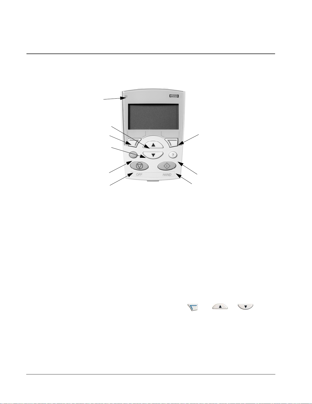
HVAC Control Panel Features
The ACH550 HVAC control panel (ACS-CP-B) features:
Status LED
(Green when normal,
if flashing or red,
see Diagnostics.)
UP
SOFT
KEY 1
DOWN
AUTO
OFF
HAND
• Language selection for the display
• Drive connection that can be made or detached at any time
• Start-up assistant to facilitate drive commissioning
• Copy function for moving parameters to other ACH550 drives
• Backup function for saving parameter sets
• Context sensitive help
• Real-time clock
General Display Features
SOFT
KEY 2
HELP (always available)
X0201
Start-Up
Soft Key Functions
The soft key functions are defined by text displayed just above each key.
Display Contrast
To adjust display contrast, simultaneously press and or , as
appropriate.
Page 23
ACH550-UH User’s Manual 23
Start-Up
Start-Up can be performed in two ways:
• Using the Start-Up Assistant.
• Changing the parameters individually.
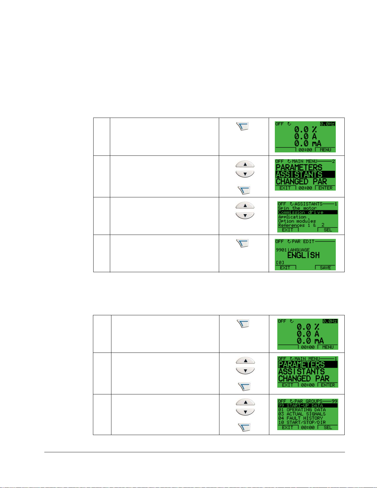
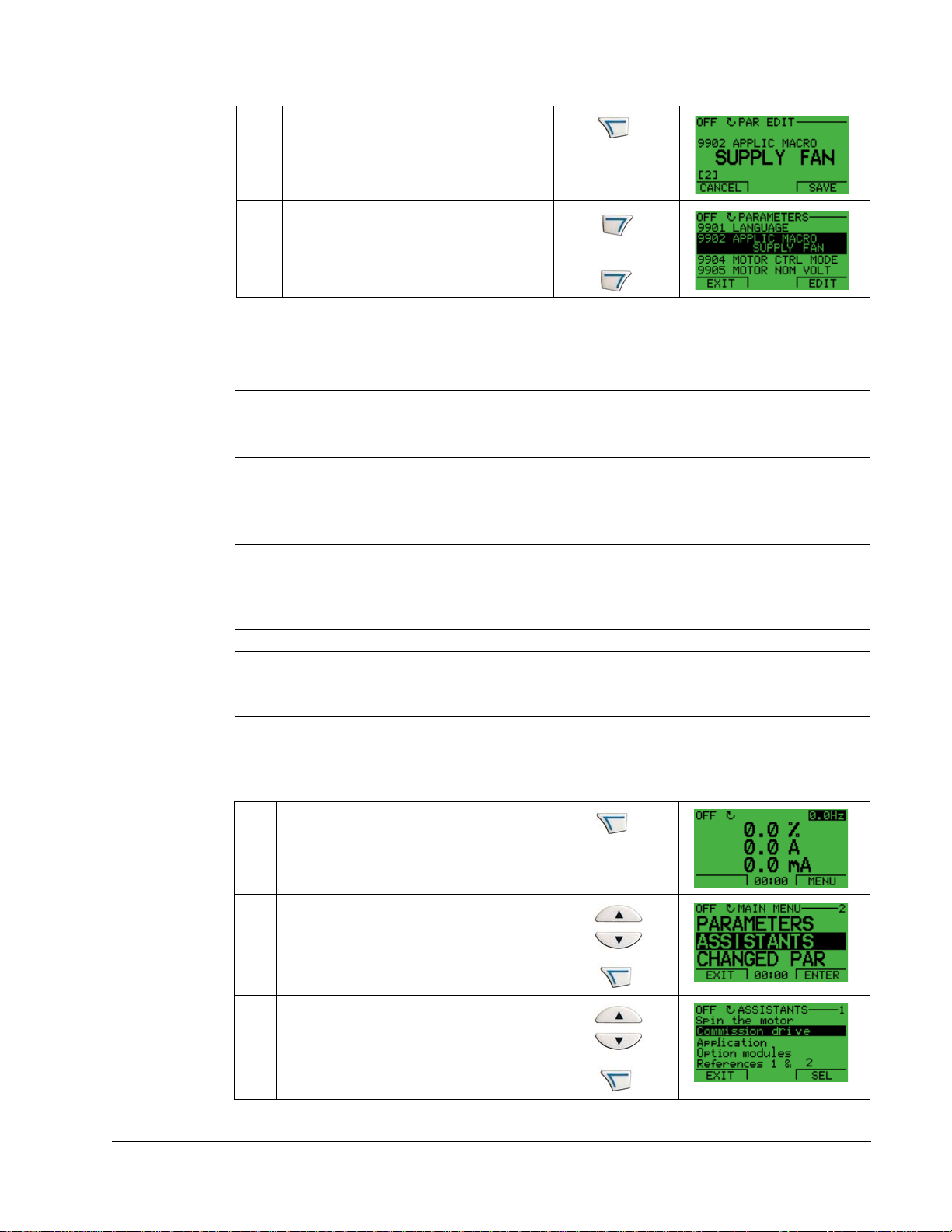
Start-Up by Using the Start-Up Assistant
To start the Start-Up Assistant, follow these steps:
Select MENU to enter the main menu
1
Select ASSISTANTS with the Up/Down
buttons and select ENTER.
2
Scroll to COMMISSION DRIVE with the
Up/Down buttons.
3
Change the values suggested by the
assistant to your preferences and then
press SAVE after every change.
4
The Start-Up Assistant will guide you through the start-up.
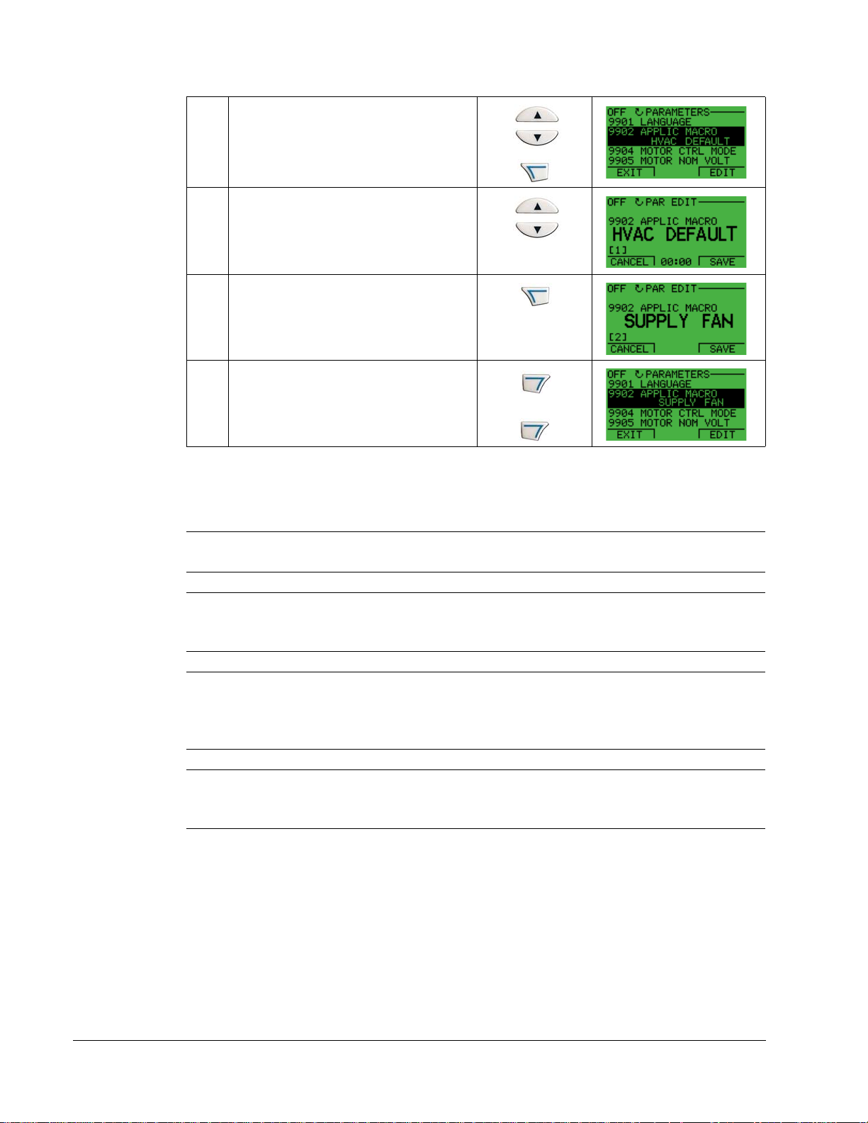
Start-Up by Changing the Parameters Individually
To change the parameters, follow these steps:
Select MENU to enter the main menu.
1
Select the Parameters mode with the UP/
DOWN buttons and select ENTER to
select the Parameters mode.
2
Select the appropriate parameter group
with the UP/DOWN buttons and select
SEL
3
Start-Up
Page 24
24 ACH550-UH User’s Manual
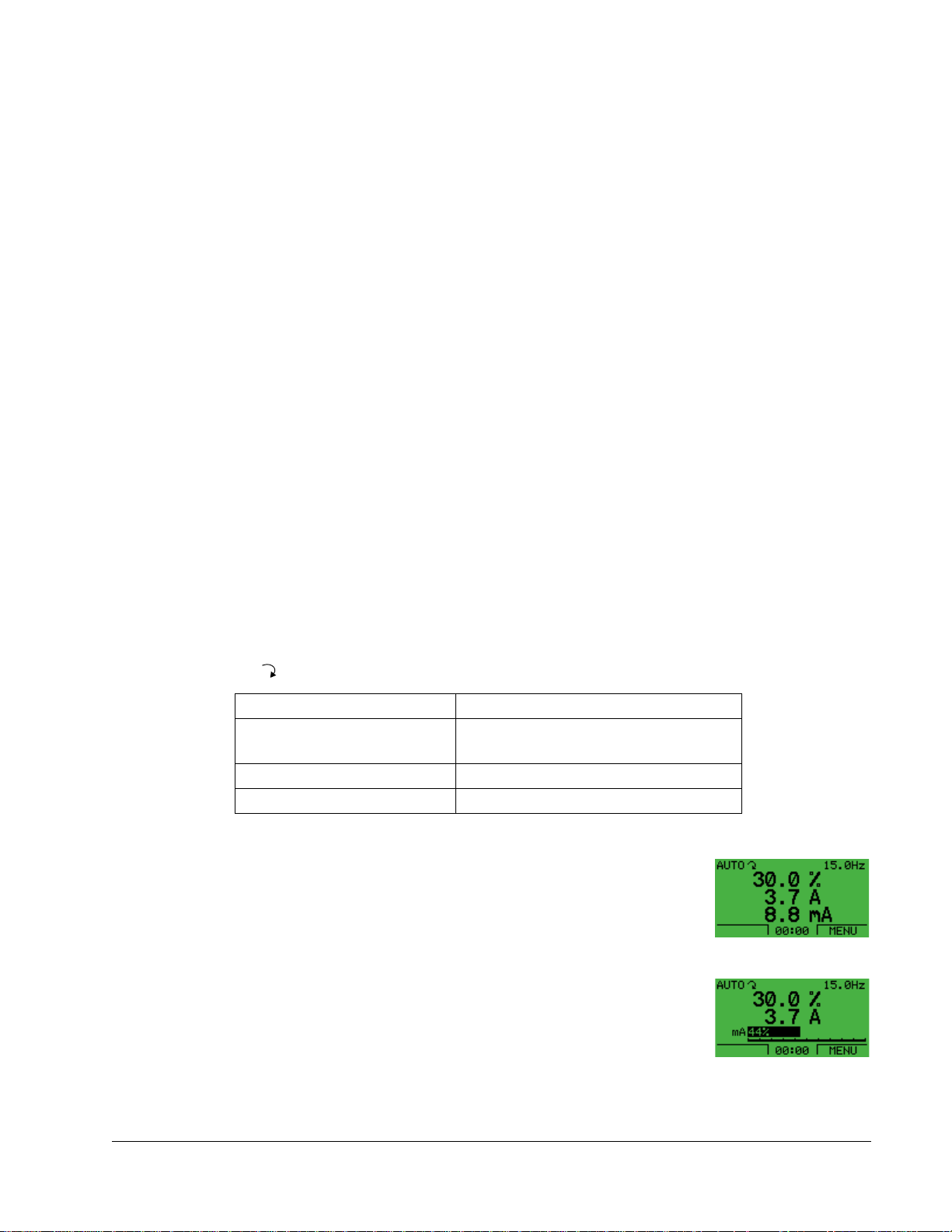
Select the appropriate parameter in a
group with the UP/DOWN buttons.Select
EDIT to change the parameter value.
4
Press the UP/DOWN buttons to change
the parameter value.
5
Select SAVE to store the modified value or
select CANCEL to leave the set mode.
Any modifications not saved are
6
cancelled.
Select EXIT to return to the listing of
parameter groups, and again to return to
the main menu.
7
To complete the control connections by manually entering the parameters, see
"Parameters Mode" in this section.
For detailed hardware description, see the "Technical Data" section.
Note! The current parameter value appears below the highlighted parameter.
Note! To view the default parameter value, press the UP/DOWN buttons
simultaneously.
Note! The most typical and necessary parameters to change are parameter groups
99 Start-up data, 10 Start/Stop/Dir, 11 Reference Select, 20 Limits, 21 Start/Stop, 22
Accel/Decel, 26 Motor Control and 30 Fault Functions.
Note! To restore the default factory settings, select the application macro HVAC
default.
Start-Up
Page 25
ACH550-UH User’s Manual 25
Modes
The HVAC control panel has several different modes for configuring, operating and
diagnosing the drive. The modes are:
• Standard display mode – Shows drive status information and operates the
drive.
• Parameters mode – Edits parameter values individually.
• Start-up assistant mode – Guides the start-up and configuration.
• Changed parameters mode – Shows changed parameters.
• Drive parameter backup mode – Stores or uploads the parameters.
• Clock set mode – Sets the time and date for the drive.
• I/O settings mode –Checks and edits the I/O settings.
Standard Display Mode
Use the standard display mode to read information on the drive’s status and to
operate the drive. To reach the standard display mode, press EXIT until the LCD
display shows status information as described below.
Status Information
Top. The top line of the LCD display shows the basic status information of the drive.
•HAND – Indicates that the drive control is local, that is, from the control panel.
•AUTO – Indicates that the drive control is remote, such as the basic I/O (X1) or
fieldbus.
• – Indicates the drive and motor rotation status as follows:
Control panel display Significance
Rotating arrow (clockwise or
counterclockwise)
Rotating arrow blinking Drive is running but not at setpoint
Stationary arrow Drive is stopped
• Drive is running and at setpoint
• Shaft direction is forward or reverse
• Upper right – shows the active reference.
Middle. Using parameter group 34, the middle of the LCD
display can be configured to display:
• One to three parameter values – The default display shows
parameters 0103 (OUTPUT FREQ) in percentages, 0104
(CURRENT) in amperes and 0120 (AI1) in milliamperes.
• A bar meter rather than one of the parameter values.
Bottom. The bottom of the LCD display shows:
• Lower corners – show the functions currently assigned to
the two soft keys.
• Lower middle – displays the current time (if configured to show the time).
Start-Up
Page 26
26 ACH550-UH User’s Manual
Operating the Drive
AUTO/HAND – The very first time the drive is powered up, it is in the auto control
(AUTO) mode, and is controlled from the Control terminal block X1.
To switch to hand control (HAND) and control the drive using the control panel, press
and hold the
or button.
• Pressing the HAND button switches the drive to hand control while keeping the
drive running.
• Pressing the OFF button switches to hand control and stops the drive.
To switch back to auto control (AUTO), press and hold the button.
Hand/Auto/Off – To start the drive press the HAND or AUTO buttons, to stop the
drive press the OFF button.
Reference – To modify the reference (only possible if the display in the upper right
corner is in reverse video) press the UP or DOWN buttons (the reference changes
immediately).
The reference can be modified in the local control mode, and can be parameterized
(using Group 11 reference select) to also allow modification in the remote control
mode.
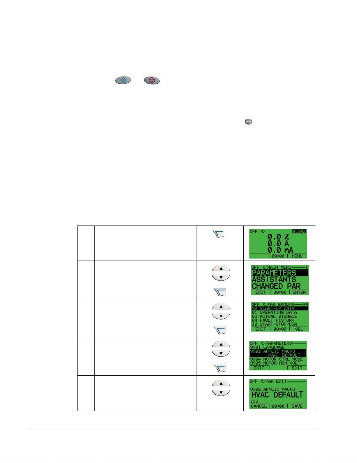
Parameters Mode
To change the parameters, follow these steps:
Select MENU to enter the main menu.
1
Select the Parameters mode with the UP/
DOWN buttons, and select ENTER to
select the Parameters mode.
2
Select the appropriate parameter group
with the UP/DOWN buttons and select
SEL
3
Select the appropriate parameter in a
group with the UP/DOWN buttons. Select
EDIT to change the parameter.
4
Start-Up
Press the UP/DOWN buttons to change
the parameter value.
5
Page 27
ACH550-UH User’s Manual 27
Select SAVE to store the modified value
or select CANCEL to leave the set mode.
Any modifications not saved are
6
cancelled.
Select EXIT to return to the listing of
parameter groups, and again to return to
the main menu.
7
To complete the control connections by manually entering the parameters, see
"Parameters Mode" in the this section.
For detailed hardware description, see the Appendix.
Note! The current parameter value appears below the highlighted parameter.
Note! To view the default parameter value, press the UP/DOWN buttons
simultaneously.
Note! The most typical and necessary parameters to change are parameter groups
99 Start-up data, 10 Start/Stop/Dir, 11 Reference Select, 20 Limits, 21 Start/Stop, 22
Accel/Decel, 26 Motor Control and 30 Fault Functions.
Note! To restore the default factory settings, select the application macro HVAC
default.
Start-Up Assistant Mode
To start the Start-Up Assistant, follow these steps:
Select MENU to enter the main menu
1
Select ASSISTANTS with the Up/Down
buttons and select ENTER.
2
Scroll to COMMISSION DRIVE with the
Up/Down buttons and select SEL.
3
Start-Up
Page 28

28 ACH550-UH User’s Manual
Change the values suggested by the
assistant to your preferences and then
press SAVE after every change.
4
The Start-Up Assistant will guide you through the start-up.
The Start-Up Assistant guides you through the basic programming of a new drive.
(You should familiarize yourself with basic control panel operation and follow the
steps outlined above.) At the first start, the drive automatically suggest s entering th e
first task, Language Select.The assistant also checks the values entered to prevent
entries that are out of range.
The St art-Up Assist ant is divided into tasks. You may activate the tasks one after t he
other, as the Start-Up Assistant suggests, or independently.
Note! If you want to set the parameters independently, use the Parameters mode.
The order of tasks presented by the S t art-up Assista nt depends on your entries. The
following task list is typical.
Task name Description
Spin the motor • Prompts for control panel display language selection.
• Prompts for motor data.
• Guides user through rotation check.
Commission drive Prompts for motor data.
Application Prompts for application macro selection.
References 1 & 2 • Prompts for the source of speed references 1 and 2.
• Prompts for reference limits.
• Prompts for frequency (or speed) limits.
Start/Stop Control • Prompts for the source for start and stop commands.
• Prompts for start and stop mode definition.
• Prompts for acceleration and deceleration times.
Protections • Prompts for current and torque limits.
• Prompts for the use of Run enable and Start enable signals.
• Prompts for the use of emergency stop.
• Prompts for Fault function selection.
• Prompts for Auto reset functions selection.
Constant Speeds • Prompts for the use of constant speeds.
• Prompts for constant speed values.
PID Control • Prompts for PID settings.
• Prompts for the source of process reference.
• Prompts for reference limits.
• Prompts for source, limits and units for the process actual value.
• Defines the use of Sleep function.
Low Noise Setup • Prompts for switching frequency.
• Prompts for definition of Flux optimization.
• Prompts for the use of Critical speeds.
Start-Up
Page 29
ACH550-UH User’s Manual 29
Task name Description
Panel Display Prompts for display variable and unit settings.
Timed Functions Prompts for the use of Timed functions.
Output • Prompts for the signals indicated through the relay outputs.
• Prompts for signals indicated through the analog outputs AO1 and AO2.
Sets the minimum, maximum, scaling and inversion values.
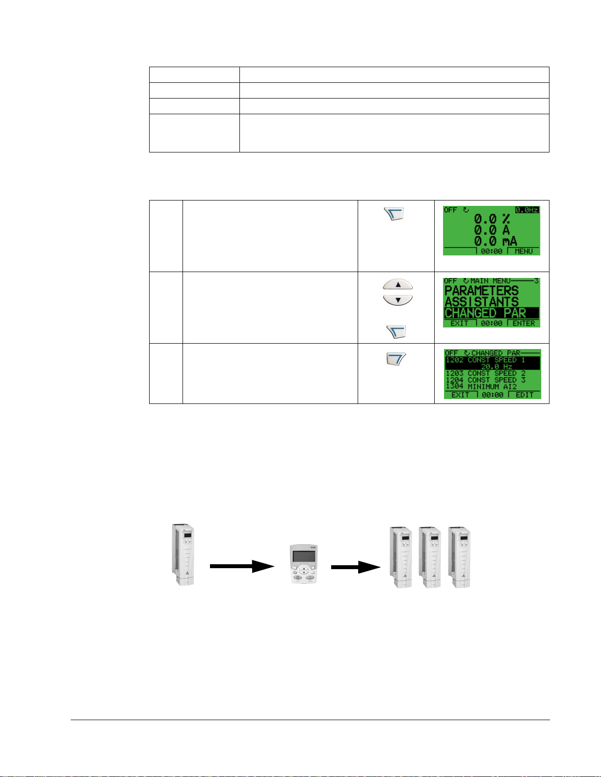
Changed Parameters Mode
To view changed parameters, follow these steps:
Select MENU to enter the menu.
1
Select CHANGED PAR with the UP/
DOWN buttons and select ENTER.
2
A list of changed parameters is displayed.
Select EXIT to exit the parameters mode.
3
Drive Parameter Backup Mode
Use the parameter backup mode to export parameters from one drive to another.
The parameters are uploaded from a drive to the control panel and downloaded from
the control panel to another drive. Two options are available:
• Download all – copies all application and motor parameters to the drive. Useful
where drives of the same size use the same application. Also useful to create a
backup for recovery if drive parameters are corrupted or erased.
Control
Upload
to panel
IP2100
Panel
X0202
Download
all
IP2100
Start-Up
Page 30
30 ACH550-UH User’s Manual
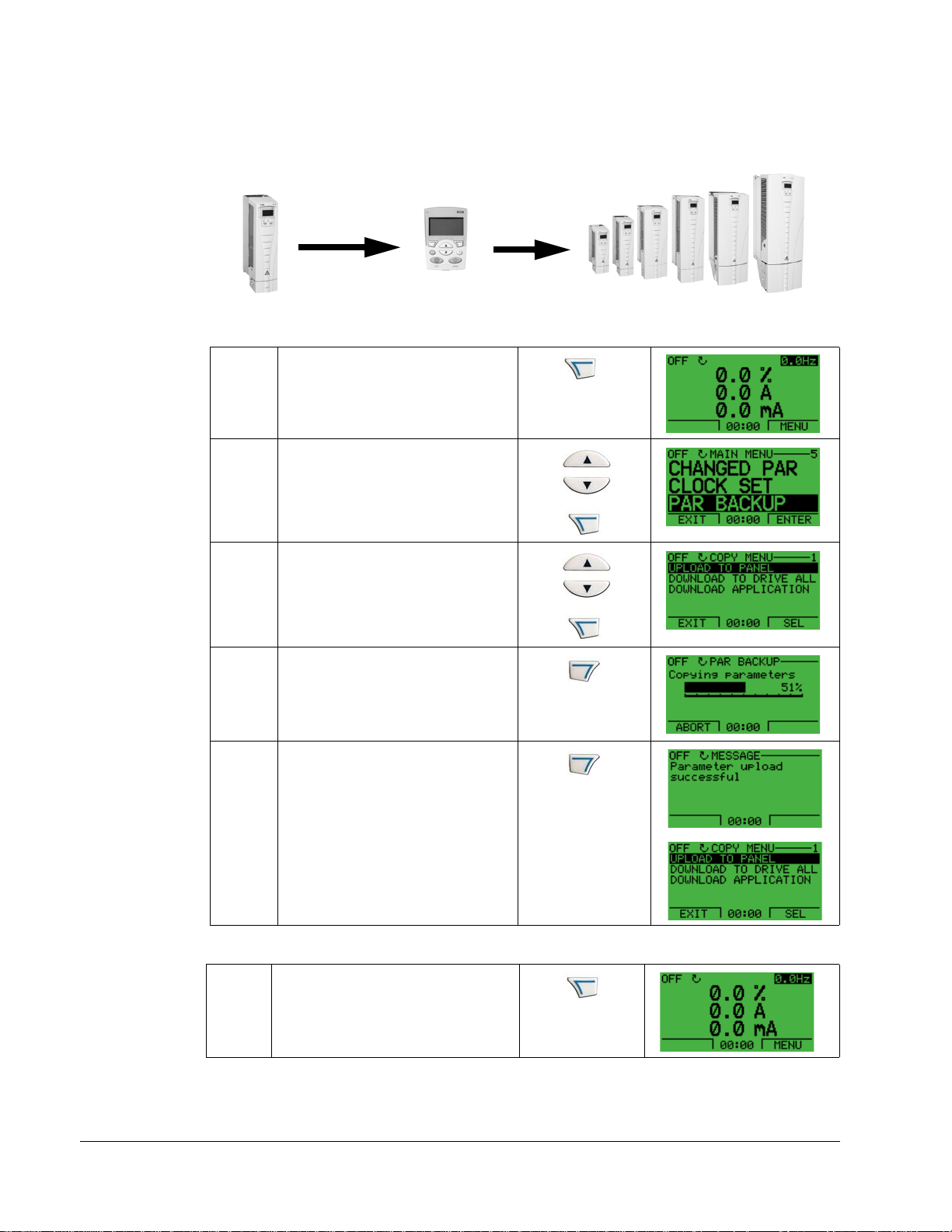
• Download application – copies only the application to the drive. Useful where
drives of different sizes use the same application. Parameters 9905...9909, 1605,
1607, 5201, group 51 parameters and internal motor p arameters are NOT copied.
Control
IP2100
Upload
to panel
Panel
X0202
Download
application
IP2101
To upload parameters to control panel, follow these steps:
Select MENU to enter the main
menu.
1
Select PAR BACKUP with the UP/
DOWN buttons and select ENTER.
2
Scroll to Upload to Panel and select
SEL.
3
The text “Copying parameters” and a
progress diagram is displayed.
Select ABORT if you want to stop
4
the process.
The text “Parameter upload
successful” is displayed and the
control panel returns to the PAR
BACKUP menu. Select EXIT to
return to the main menu. Now you
can disconnect the panel.
5
To download all parameters to drive, follow these steps:
Select MENU to enter the menu.
Start-Up
1
Page 31

ACH550-UH User’s Manual 31
Select PAR BACKUP with the UP/
DOWN buttons.
2
Scroll to Download to drive all and
select SEL.
3
The text “restoring parameters” is
displayed. Select ABORT if you want
to stop the process.
4
After the download stops, the
message “Parameter download
successful” is displayed and the
control panel goes back to PAR
BACKUP menu. Select EXIT to return
to the main menu.
5
To download application to drive, follow these steps:
Select MENU to enter the menu.
1
Select PAR BACKUP with the UP/
DOWN buttons.
2
Scroll to DOWNLOAD APPLICATION
and select SEL.
3
The text “Downloading parameters
(partial)” is displayed. Select ABORT
if you want to stop the process.
4
Start-Up
Page 32

32 ACH550-UH User’s Manual
The text “Parameter download
successful” is displayed and the
control panel returns to P AR BACKUP
menu. Select EXIT to return to the
main menu.
5
Note! If upload or download of parameters is aborted, the partial p arameter set is not
implemented.
Clock Set Mode
The clock set mode is used for setting the time and date for the internal clock of the
ACH550. In order to use the timer functions of the ACH550, the internal clock has to
be set first. Date is used to determine weekdays and is visible in Fault logs.
To set the clock, follow these steps:
Select MENU to enter the main menu.
1
Scroll to Clock Set with the UP/DOWN
buttons and select ENTER to enter the
Clock Set mode.
2
Scroll to Clock Visibility with the UP/
DOWN buttons and select SEL to change
the visibility of the clock.
3
Scroll to Show Clock with the UP/DOWN
buttons and select SEL to make the clock
visible.
4
Scroll to Set Time with the UP/DOWN
buttons and select SEL.
5
Start-Up
Page 33

ACH550-UH User’s Manual 33
Change the hours and minutes with the
UP/DOWN buttons and select OK to save
the values. The active value is displayed
6
in inverted color.
Scroll to Time Format with the UP/DOWN
buttons and select SEL.
7
The different formats are displayed.
Select a format with the UP/DOWN
buttons and select SEL to confirm the
8
selection.
Scroll to Set Date with the UP/DOWN
buttons and select SEL.
9
Change the days, months and year with
the UP/DOWN buttons and select OK to
save the values. The active value is
10
displayed in inverted color.
Scroll to Date Format with the UP/DOWN
buttons and select SEL.
11
The Date formats are displayed . Sel e ct a
date format with the UP/DOWN buttons
and select OK to confirm the selection.
12
Select EXIT twice to return to the main
menu.
13
Start-Up
Page 34

34 ACH550-UH User’s Manual
I/O Settings Mode
To view and edit the I/O settings, follow these steps:
Select MENU to enter the main menu.
1
Scroll to I/O Settings with the UP/DOWN
buttons and select ENTER.
2
Scroll to the I/O setting you want to view
with the UP/DOWN buttons and select
SEL.
3
Select the setting you want to view with
the UP/DOWN buttons and select OK.
4
You can change the value with the UP/
DOWN buttons and save it by selecting
SAVE.
5
If you do not want to change the setting,
select CANCEL.
Select EXIT to return to the main menu.
6
Start-Up
Page 35

ACH550 User’s Manual 35
Application Macros
Overview
Macros change a group of parameters to new, predefined values designed for
specific applications. Use macros to minimize the need for manual editing of
parameters. Selecting a macro sets all other parameters to their default values,
except:
• Group 99: Start-up Data parameters
• The PARAMETER LOCK 1602
• The PARAM SAVE 1607
• Groups 50…52 serial communication parameters
• Group 29: Maintenance triggers
After selecting a macro, additional parameter changes can be made manually using
the control panel.
Application macros are enabled by setting the value for parameter 9902
MACRO. By default, HVAC default (value 1) is the enabled macro.
APPLIC
General Considerations
The following considerations apply for all macros:
• When using a direct speed reference in AUTO mode, connect the speed
reference to analog input 1 (AI1), and provide the START command using digital
input 1 (DI1). In HAND/OFF mode, the control panel provides the speed
reference and START command.
• When using process PID, connect the feedback signal to analog input 2 (AI2). As
a default, the control panel sets the Setpoint, but analog input 1 can be used as
an alternate source. You can set up process PID using parameters (Group 40) or
using the PID control assistant (recommended).
Application / Macro Listing
This section describes the following macros:
9902
Value
1 HVAC default
2 Supply fan 9 Internal timer with constant speeds
3 Return fan
4 Cooling tower fan
5 Condenser 12 Dual setpoint PID with constant speeds
6 Booster pump
7 Pump alternation
Macro
9902
Value
8 Internal timer
10 Floating point
11 Dual setpoint PID
13 E-bypass
14 Hand Control
Macro
Start-Up
Page 36

36 ACH550 User’s Manual
Selecting an Application Macro
To select a macro, follow these steps:
Select MENU to enter the main menu.
1
Select ASSISTANTS with the Up/Down
buttons and select ENTER.
2
Scroll to APPLICATION and select
ENTER.
3
Select a macro with the Up/Down buttons
and select SAVE.
4
Restoring Defaults
To restore the factory default settings, select the application macro HVAC Default.
Control Wiring
Each macro has specific requirements for control wiring. For general details about
the ACH550 control wiring terminals, see “Control Terminal Descriptions” on
page 238. Specific wiring requirements are included with each macro description.
Start-Up
Page 37

ACH550 User’s Manual 37
HVAC Default
This macro provides the factory default parameter settings for the ACS550-UH.
Factory defaults can be restored at any time by setting parameter 9902 to 1. The
diagram below shows typical wiring using this macro. When using direct speed
reference in AUTO mode or process PID, see "General Considerations" on page 35.
X1
1SCR
+
2AI1
3AGND
4 10V
+
5AI2
6AGND
mA
mA
7AO1
8AO2
9AGND
Signal cable shield (screen)
External reference 0(2)…10 V or 0(4)…20 mA
Analog input circuit common
Reference voltage 10 VDC
PID feedback: 0(2)…10 V or 0(4)…20 mA
Analog input circuit common
Output frequency: 0(4)…20 mA
Output current: 0(4)…20 mA
Analog output circuit common
ON
J1
Jumper Settings
AI1: 0(2)
ON
AI2: 0(4)
…10 V
…20 mA
10 24V
11 GND
12 DCOM1
13 DI1
14 DI2
15 DI3
16 DI4
17 DI5
18 DI6
19 RO1C
20 RO1A
21 RO1B
22 RO2C
23 RO2A
24 RO2B
25 RO3C
26 RO3A
27 RO3B
Parameter Value
None (Default macro)
Auxiliary voltage output +24 VDC
Common for DI return signals.
Digital input common for all
Start/Stop: Activate to start drive
Not configured
Constant (Preset) speed 1 (P 1202)
Safety interlock: Deactivate to stop drive (P 1608)
Not configured
Not configured
Relay output 1 (P 1401)
Default operation: Ready =>19 connected to 21
Relay output 2 (P 1402)
Default operation: Running =>22 connected to 24
Relay output 3 (P 1403)
Default operation: Fault (-1) =>25 connected to 27
(Fault => 25 connected to 26)
Parameters Changed Relative to HVAC Default
Parameter Value
Start-Up
Page 38

38 ACH550 User’s Manual
Supply Fan
This macro configures for supply fan applications where the supply fan brings fresh
air in according to signals received from a transducer. When using direct speed
reference in AUTO mode or process PID, see "General Considerations" on page 35.
X1
1SCR
+
2AI1
3AGND
4 10V
+
5AI2
6AGND
mA
mA
7AO1
8AO2
9AGND
10 24V
11 GND
12 DCOM1
13 DI1
14 DI2
15 DI3
16 DI4
17 DI5
18 DI6
19 RO1C
20 RO1A
Signal cable shield (screen)
External reference 0(2)…10 V or 0(4)…20 mA
Analog input circuit common
Reference voltage 10 VDC
PID feedback: 0(2)…10 V or 0(4)…20 mA
Analog input circuit common
Output frequency: 0(4)…20 mA
Output current: 0(4)…20 mA
ON
J1
ON
Analog output circuit common
Auxiliary voltage output +24 VDC
Common for DI return signals.
Digital input common for all
Start/Stop: Activate to start drive
Run permissive: Deactivate to stop drive (P 1601)
Constant (Preset) speed 1 (P 1202
1
)
Safety interlock 1: Deactivate to stop drive (P 1608)
Safety interlock 2: Deactivate to stop drive (P 1609)
Not configured
Relay output 1 (P 1401)
Default operation: Ready =>19 connected to 21
Jumper Settings
AI1: 0(2)
AI2: 0(4)
…10 V
…20 mA
21 RO1B
22 RO2C
23 RO2A
Relay output 2 (P 1402)
Default operation: Running =>22 connected to 24
24 RO2B
25 RO3C
26 RO3A
27 RO3B
Relay output 3 (P 1403)
Default operation: Fault (-1) =>25 connected to 27
(Fault => 25 connected to 26)
Parameters Changed Relative to HVAC Default
Parameter Value
9902
APPLIC MACRO 2 (SUPPLYFAN) 3207 SUPERV 3 PARAM 0103 (OUTPUT FREQ)
RELAY OUTPUT 17 (STARTED) 4001 GAIN 0.7
1401
1601
RUN ENABLE 2 (DI2) 4002 INTEGRATION TIME 10.0 s
1609
START ENABLE 25 (DI5) 4101 GAIN 1.0
Parameter Value
2202 ACCELER TIME 1 15.0 s 4102 INTEGRATION TIME 60.0 s
2203
DECELER TIME 1 15.0 s
Start-Up
Page 39

ACH550 User’s Manual 39
Return Fan
This macro configures for return fan applications where the return fan removes air
according to signals received from a transducer. When using direct speed reference
in AUTO mode or process PID, see "General Considerations" on page 35.
X1
1SCR
+
2AI1
3AGND
4 10V
+
5AI2
6AGND
mA
mA
7AO1
8AO2
9AGND
Signal cable shield (screen)
External reference 0(2)…10 V or 0(4)…20 mA
Analog input circuit common
Reference voltage 10 VDC
PID feedback: 0(2)…10 V or 0(4)…20 mA
Analog input circuit common
Output frequency: 0(4)…20 mA
Output current: 0(4)…20 mA
Analog output circuit common
ON
J1
Jumper Settings
AI1: 0(2)
ON
AI2: 0(4)
…10 V
…20 mA
10 24V
11 GND
12 DCOM1
13 DI1
14 DI2
15 DI3
16 DI4
17 DI5
18 DI6
19 RO1C
20 RO1A
Auxiliary voltage output +24 VDC
Common for DI return signals.
Digital input common for all
Start/Stop: Activate to start drive
Run permissive: Deactivate to stop drive (P 1601)
Constant (Preset) speed 1 (P 1202
1
)
Safety interlock 1: Deactivate to stop drive (P 1608)
Safety interlock 2: Deactivate to stop drive (P 1609)
Not configured
Relay output 1 (P 1401)
Default operation: Ready =>19 connected to 21
21 RO1B
22 RO2C
23 RO2A
Relay output 2 (P 1402)
Default operation: Running =>22 connected to 24
24 RO2B
25 RO3C
26 RO3A
27 RO3B
Relay output 3 (P 1403)
Default operation: Fault (-1) =>25 connected to 27
(Fault => 25 connected to 26)
Parameters Changed Relative to HVAC Default
Parameter Value
9902
APPLIC MACRO 3 (RETURNFAN) 3207 SUPERV 3 PARAM 0103 (OUTPUT FREQ)
RELAY OUTPUT 17 (STARTED) 4001 GAIN 0.7
1401
1601
RUN ENABLE 2 (DI2) 4002 INTEGRATION TIME 10.0 s
1609
START ENABLE 25 (DI5) 4101 GAIN 1.0
Parameter Value
2202 ACCELER TIME 1 15.0 s 4102 INTEGRATION TIME 60.0 s
2203
DECELER TIME 1 15.0 s
Start-Up
Page 40

40 ACH550 User’s Manual
Cooling Tower Fan
This macro configures for cooling tower fan applications where the fan speed is
controlled according to the signals received from a transducer. When using direct
speed reference in AUTO mode or process PID, see "General Considerations" on
page 35.
X1
1SCR
+
2AI1
3AGND
410V
+
5AI2
6AGND
mA
mA
7AO1
8AO2
9AGND
10 24V
11 GND
12 DCOM1
13 DI1
14 DI2
15 DI3
16 DI4
17 DI5
18 DI6
Signal cable shield (screen)
External reference 0(2)…10 V or 0(4)…20 mA
Analog input circuit common
Reference voltage 10 VDC
PID feedback: 0(2)…10 V or 0(4)…20 mA
Analog input circuit common
Output frequency: 0(4)…20 mA
Output current: 0(4)…20 mA
ON
J1
ON
Analog output circuit common
Auxiliary voltage output +24 VDC
Common for DI return signals.
Digital input common for all
Start/Stop: Activate to start drive
Run permissive: Deactivate to stop drive (P 1601)
Constant (Preset) speed 1 (P 1202
1
)
Safety interlock 1: Deactivate to stop drive (P 1608)
Safety interlock 2: Deactivate to stop drive (P 1609)
Not configured
Jumper Settings
AI1: 0(2)
AI2: 0(4)
…10 V
…20 mA
19 RO1C
20 RO1A
Relay output 1 (P 1401)
Default operation: Ready =>19 connected to 21
21 RO1B
22 RO2C
23 RO2A
Relay output 2 (P 1402)
Default operation: Running =>22 connected to 24
24 RO2B
25 RO3C
26 RO3A
27 RO3B
Relay output 3 (P 1403)
Default operation: Fault (-1) =>25 connected to 27
(Fault => 25 connected to 26)
Parameters Changed Relative to HVAC Default
Parameter Value
Parameter Value
9902 APPLIC MACRO 4 (CLNGTWRFAN) 3207 SUPERV 3 PARAM 0103 (OUTPUT FREQ)
1401
RELAY OUTPUT 17 (STARTED) 4101 GAIN 1.0
1601 RUN ENABLE 2 (DI2) 4102 INTEGRATION TIME 60.0 s
1609
START ENABLE 25 (DI5)
Start-Up
Page 41

ACH550 User’s Manual 41
Condenser
This macro configures for condenser and liquid cooler applications where fan speed
is controlled according to signals received from a transducer. When using direct
speed reference in AUTO mode or process PID, see "General Considerations" on
page 35.
X1
1SCR
+
2AI1
3AGND
410V
+
5AI2
6AGND
mA
mA
7AO1
8AO2
9AGND
10 24V
11 GND
12 DCOM1
13 DI1
14 DI2
15 DI3
16 DI4
17 DI5
18 DI6
Signal cable shield (screen)
External reference 0(2)…10 V or 0(4)…20 mA
Analog input circuit common
Reference voltage 10 VDC
PID feedback: 0(2)…10 V or 0(4)…20 mA
Analog input circuit common
Output frequency: 0(4)…20 mA
Output current: 0(4)…20 mA
ON
J1
ON
Analog output circuit common
Auxiliary voltage output +24 VDC
Common for DI return signals.
Digital input common for all
Start/Stop: Activate to start drive
Run permissive: Deactivate to stop drive (P 1601)
Constant (Preset) speed 1 (P 1202
1
)
Safety interlock 1: Deactivate to stop drive (P 1608)
Safety interlock 2: Deactivate to stop drive (P 1609)
Not configured
Jumper Settings
AI1: 0(2)
AI2: 0(4)
…10 V
…20 mA
19 RO1C
20 RO1A
Relay output 1 (P 1401)
Default operation: Ready =>19 connected to 21
21 RO1B
22 RO2C
23 RO2A
Relay output 2 (P 1402)
Default operation: Running =>22 connected to 24
24 RO2B
25 RO3C
26 RO3A
27 RO3B
Relay output 3 (P 1403)
Default operation: Fault (-1) =>25 connected to 27
(Fault => 25 connected to 26)
Parameters Changed Relative to HVAC Default
Parameter Value
Parameter Value
9902 APPLIC MACRO 5 (CONDENSER) 2203 DECELER TIME 1 10.0 s
1401
RELAY OUTPUT 17 (STARTED) 3207 SUPERV 3 PARAM 0103 (OUTPUT FREQ)
1601 RUN ENABLE 2 (DI2) 4005 ERROR VALUE INV 1 (YES)
1609
START ENABLE 25 (DI5) 4101 GAIN 1.0
2202
ACCELER TIME 1 10.0 s 4102 INTEGRATION TIME 60.0 s
Start-Up
Page 42

42 ACH550 User’s Manual
Booster Pump
This macro configures for booster pump applications where the pump speed is
controlled according to a signal received from a transducer . Whe n using direct speed
reference in AUTO mode or process PID, see "General Considerations" on page 35.
X1
1SCR
+
2AI1
3AGND
410V
+
5AI2
6AGND
mA
mA
7AO1
8AO2
9AGND
10 24V
11 GND
12 DCOM1
13 DI1
14 DI2
15 DI3
16 DI4
17 DI5
18 DI6
Signal cable shield (screen)
External reference 0(2)…10 V or 0(4)…20 mA
Analog input circuit common
Reference voltage 10 VDC
PID feedback: 0(2)…10 V or 0(4)…20 mA
Analog input circuit common
Output frequency: 0(4)…20 mA
Output current: 0(4)…20 mA
ON
J1
ON
Analog output circuit common
Auxiliary voltage output +24 VDC
Common for DI return signals.
Digital input common for all
Start/Stop: Activate to start drive
Run permissive: Deactivate to stop drive (P 1601)
Constant (Preset) speed 1 (P 12021)
Safety interlock 1: Deactivate to stop drive (P 1608)
Safety interlock 2: Deactivate to stop drive (P 1609)
Not configured
Jumper Settings
AI1: 0(2)
AI2: 0(4)
…10 V
…20 mA
19 RO1C
20 RO1A
Relay output 1 (P 1401)
Default operation: Ready =>19 connected to 21
21 RO1B
22 RO2C
23 RO2A
Relay output 2 (P 1402)
Default operation: Running =>22 connected to 24
24 RO2B
25 RO3C
26 RO3A
27 RO3B
Relay output 3 (P 1403)
Default operation: Fault (-1) =>25 connected to 27
(Fault => 25 connected to 26)
Parameters Changed Relative to HVAC Default
Parameter Value Parameter Value
9902
APPLIC MACRO 6 (BOOSTERPUMP) 2203 DECELER TIME 1 5.0 s
RELAY OUTPUT 17 (STARTED) 3207 SUPERV 3 PARAM 0 103 ( OUTPUT FREQ)
1401
1601
RUN ENABLE 2 (DI2) 4001 GAIN 1.0
1609
START ENABLE 25 (DI5) 4002 INTEGRATION TIME 60.0 s
ACCELER TIME 1 5.0 s
2202
Start-Up
Page 43

ACH550 User’s Manual 43
Pump Alternation
This macro configures for pump alternation applications, usually used in booster
stations. To adjust/maintain pressure in the network, the speed of the one pump
changes according to a signal received from a pressure transducer. When the
variable speed pump reaches a maximum speed limit, auxiliary pumps start as
needed. When using process PID, see "General Considerations" on page 35. To use
more than one (the default) Auxiliary pump, see parameter group 81.
X1
1SCR
+
2AI1
3AGND
410V
+
5AI2
6AGND
mA
mA
7AO1
8AO2
9AGND
10 24V
11 GND
12 DCOM1
13 DI1
14 DI2
15 DI3
16 DI4
17 DI5
18 DI6
Signal cable shield (screen)
External reference 0(2)…10 V or 0(4)…20 mA
Analog input circuit common
Reference voltage 10 VDC
PID feedback: 0(2)…10 V or 0(4)…20 mA
Analog input circuit common
Output frequency: 0(4)…20 mA
Output current: 0(4)…20 mA
ON
J1
ON
Analog output circuit common
Auxiliary voltage output +24 VDC
Common for DI return signals.
Digital input common for all
Start/Stop: Activate to start drive
Run permissive: Deactivate to stop drive (P 1601)
Not configured
PFA interlock 1: Deactivate to stop drive (P 1608)
PFA interlock 2: Deactivate to stop drive (P 1609)
Not configured
Jumper Settings
AI1: 0(2)
AI2: 0(4)
…10 V
…20 mA
19 RO1C
20 RO1A
Relay output 1 (P 1401)
Default operation: PFA (starts lag pump)
21 RO1B
22 RO2C
23 RO2A
Relay output 2 (P 1402)
Default operation: Running =>22 connected to 24
24 RO2B
25 RO3C
26 RO3A
27 RO3B
Relay output 3 (P 1403)
Default operation: Fault (-1) =>25 connected to 27
(Fault => 25 connected to 26)
Parameters Changed Relative to HVAC Default
Parameter Value
9902
APPLIC MACRO 7 (PUMPALTERN) 1609 START ENABLE 25 (DI5)
REF1 MAX 62Hz/1860rpm 2208 EM DEC TIME 62HZ
1105
Parameter Value
1201 CONST SPEED SEL 0 (NOT SEL) 2202 ACCELER TIME 1 5.0 s
1401
RELAY OUTPUT 1 31 (PFA) 2203 DECELER TIME 1 5.0 s
AO1 CONTENT MAX 62HZ 3207 SUPERV 3 PARAM 0103 (OUTPUT FREQ)
1503
1508
AO2 CONTENT MIN 0.0% 4101 GAIN 1.0
1509
AO2 CONTENT MAX 100.0% 4102 INTEGRATION TIME 60.0 s
RUN ENABLE 2 (DI2) 8123 PFA ENABLE 1 (ACTIVE)
1601
1608
START ENABLE 10 (NOT SEL)
Start-Up
Page 44

44 ACH550 User’s Manual
Internal Timer
This macro configures for applications where a built-in timer starts and stops the
motor. When the variable speed pump reaches a maximum speed limit, auxiliary
pumps start as needed. When using direct speed reference in AUTO mode or
process PID, see "General Considerations" on page 35.
Momentarily activating digital input 3 (DI3) provides a b oost fu nction which operates
the motor. See group 36, Timer Functions, for more information on setting up timers.
X1
1SCR
+
2AI1
3AGND
410V
+
5AI2
6AGND
mA
mA
7AO1
8AO2
9AGND
10 24V
11 GND
12 DCOM1
13 DI1
14 DI2
15 DI3
16 DI4
17 DI5
18 DI6
Signal cable shield (screen)
External reference 0(2)…10 V or 0(4)…20 mA
Analog input circuit common
Reference voltage 10 VDC
PID feedback: 0(2)…10 V or 0(4)…20 mA
Analog input circuit common
Output frequency: 0(4)…20 mA
Output current: 0(4)…20 mA
ON
J1
ON
Analog output circuit common
Auxiliary voltage output +24 VDC
Common for DI return signals.
Digital input common for all
Timer enable: Activate to start/stop drive from timer
Run permissive: Deactivate to stop drive (P 1601)
Timer override: Activate to start drive
Safety interlock 1: Deactivate to stop drive (P 1608)
Safety interlock 2: Deactivate to stop drive (P 1609)
Not configured
Jumper Settings
AI1: 0(2)
AI2: 0(4)
…10 V
…20 mA
19 RO1C
20 RO1A
Relay output 1 (P 1401)
Default operation: Started =>19 connecte d to 21
21 RO1B
22 RO2C
23 RO2A
Relay output 2 (P 1402)
Default operation: Running =>22 connected to 24
24 RO2B
25 RO3C
26 RO3A
27 RO3B
Relay output 3 (P 1403)
Default operation: Fault (-1) =>25 connected to 27
(Fault => 25 connected to 26)
Parameters Changed Relative to HVAC Default
Parameter Value
9902
APPLIC MACRO 8 (INT TIMER) 1609 START ENABLE 25 (DI5)
EXT1 COMMANDS 11 (TIMER1) 3207 SUPERV 3 PARAM 0103 (OUTPUT FREQ)
1001
1002
EXT2 COMMANDS 11 (TIMER1) 3601 TIMERS ENABLE 1 (DI1)
1201
CONST SPEED SEL 0 (NOT SEL) 3622 BOOST SEL 3 (DI3)
RELAY OUTPUT 17 (STARTED) 3626 TIMER 1 SRC 23 (B+P3+P2+P1)
1401
1601
RUN ENABLE 2 (DI2)
Parameter Value
Start-Up
Page 45

ACH550 User’s Manual 45
Internal Timer with Constant Speeds / PRV
This macro configures for applications such as a timed powered roof ventilator
(PRV) which alternates between two constant speeds (constant speed 1 and 2)
based on a built-in timer.
Momentarily activating digital input 3 (DI3) provides a b oost fu nction which operates
the motor. See group 36, Timer Functions, for more information on setting up timers.
X1
1SCR
+
2AI1
3AGND
410V
5AI2
6AGND
mA
7AO1
mA
8AO2
9AGND
10 24V
11 GND
12 DCOM1
13 DI1
14 DI2
15 DI3
16 DI4
17 DI5
18 DI6
Signal cable shield (screen)
External reference 0(2)…10 V or 0(4)…20 mA
Analog input circuit common
Reference voltage 10 VDC
Not configured
Analog input circuit common
Output frequency: 0(4)…20 mA
Output current: 0(4)…20 mA
ON
J1
ON
Analog output circuit common
Auxiliary voltage output +24 VDC
Common for DI return signals.
Digital input common for all
Timer enable: Activate to start/stop drive from timer
Run permissive: Deactivate to stop drive (P 1601)
Timer override: Activate to start drive
Safety interlock 1: Deactivate to stop drive (P 1608)
Safety interlock 2: Deactivate to stop drive (P 1609)
Not configured
Jumper Settings
AI1: 0(2)
AI2: 0(4)
…10 V
…20 mA
19 RO1C
20 RO1A
Relay output 1 (P 1401)
Default operation: Started =>19 connecte d to 21
21 RO1B
22 RO2C
23 RO2A
Relay output 2 (P 1402)
Default operation: Running =>22 connected to 24
24 RO2B
25 RO3C
26 RO3A
27 RO3B
Relay output 3 (P 1403)
Default operation: Fault (-1) =>25 connected to 27
(Fault => 25 connected to 26)
Parameters Changed Relative to HVAC Default
Parameter Value
Parameter Value
9902 APPLIC MACRO 9 (INT TIMER CS) 3416 SIGNAL 3 MIN -200.0%
1002
EXT2 COMMANDS 0 (NOT SEL) 3417 SIGNAL 3 MAX 200.0%
1103
REF1 SEL 0 (KEYPAD) 3419 OUTPUT 3 DSP UNIT 4 (%)
REF3 SEL 2 (AI2) 3420 OUTPUT 3 MIN -200.0%
1106
1201
CONST SPEED SEL 15 (TIMER1) 3421 OUTPUT 3 MAX 200.0%
1301
MINIMUM AI10.0% 3622 BOOST SEL 3 (DI3)
RELAY OUTPUT 17 (STARTED) 4001 GAIN 1.0
1401
1601
RUN ENABLE 2 (DI2) 4002 INTEGRATION TIME 60.0 s
1609
START ENABLE 25 (DI5) 4101 GAIN 1.0
SUPERV 3 PARAM 0103 (OUTPUT FREQ) 4102 INTEGRATION TIME 60.0 s
3207
3415
SIGNAL 3 PARAM 0105 (TORQUE) 4110 SETPOINT SEL 1 (AI1)
Start-Up
Page 46

46 ACH550 User’s Manual
Floating Point
This application macro is for applications where speed reference needs to be
controlled through digital inputs (DI5 & DI6). By activating digital input 5, the speed
reference increases, by activating digital input 6, the speed reference decreases. If
both digital inputs are active or inactive, the reference does not change.
Note! When constant speed 1 is activated using digital input 3 (DI3), the reference
speed is the value of parameter 1202. The value remains as the reference speed
when digital input 3 is deactivated.
X1
1SCR
2AI1
3AGND
410V
5AI2
6AGND
mA
mA
7AO1
8AO2
9AGND
10 24V
11 GND
12 DCOM1
13 DI1
14 DI2
15 DI3
16 DI4
17 DI5
18 DI6
19 RO1C
20 RO1A
Signal cable shield (screen)
Not configured
Analog input circuit common
Reference voltage 10 VDC
Not configured
Analog input circuit common
Output frequency: 0(4)…20 mA
Output current: 0(4)…20 mA
ON
J1
ON
Analog output circuit common
Auxiliary voltage output +24 VDC
Common for DI return signals.
Digital input common for all
Start/Stop: Activate to start drive
Run permissive: Deactivate to stop drive (P 1601)
Constant (Preset) speed 1 (P 1202)
1
Safety interlock 1: Deactivate to stop drive (P 1608)
Reference up: Activate to increase reference
Reference down: Activate to decrease reference
Relay output 1 (P 1401)
Default operation: Started =>19 connecte d to 21
Jumper Settings
AI1: 0(2)
AI2: 0(4)
…10 V
…20 mA
21 RO1B
22 RO2C
23 RO2A
Relay output 2 (P 1402)
Default operation: Running =>22 connected to 24
24 RO2B
25 RO3C
26 RO3A
27 RO3B
Relay output 3 (P 1403)
Default operation: Fault (-1) =>25 connected to 27
(Fault => 25 connected to 26)
Start-Up
Parameters Changed Relative to HVAC Default
Parameter Value Parameter Value
9902 APPLIC MACRO 10 (FLOATINGPNT) 3416 SIGNAL 3 MIN -200.0%
1103
REF1 SEL 7 (DI5U, 6D) 3417 SIGNAL 3 MAX 200.0%
1401
RELAY OUTPUT 17 (STARTED) 3419 OUTPUT 3 DSP UNIT 4 (%)
1601
RUN ENABLE 2 (DI2) 3420 OUTPUT 3 MIN -200.0%
3207
SUPERV 3 PARAM 0103 (OUTPUT FREQ) 3421 OUTPUT 3 MAX 200.0%
3415
SIGNAL 3 PARAM 0105 (TORQUE)
Page 47

ACH550 User’s Manual 47
Dual Setpoint with PID
This macro configures for dual setpoint PID applications, where activating digital
input 3 (DI3) changes the process PID controller’s setpoint to another value. When
using direct speed reference in AUTO mode or process PID, see "General
Considerations" on page 35. Set process PID setpoints (internal to the drive) using
parameters 4011 (
X1
+
+
mA
mA
SET1) and 4111 (SET2).
1SCR
2AI1
3AGND
410V
5AI2
6AGND
7AO1
8AO2
9AGND
10 24V
11 GND
12 DCOM1
13 DI1
14 DI2
15 DI3
16 DI4
17 DI5
18 DI6
Signal cable shield (screen)
External reference 0(2)…10 V or 0(4)…20 mA
Analog input circuit common
Reference voltage 10 VDC
PID feedback: 0(2)…10 V or 0(4)…20 mA
Analog input circuit common
Output frequency: 0(4)…20 mA
Output current: 0(4)…20 mA
Analog output circuit common
Auxiliary voltage output +24 VDC
Common for DI return signals.
Digital input common for all
Start/Stop: Activate to start drive
Run permissive: Deactivate to stop drive (P 1601)
Setpoint selection: Activate to select Set2
Safety interlock 1: Deactivate to stop drive (P 1608)
Safety interlock 2: Deactivate to stop drive (P 1609)
Not configured
ON
J1
Jumper Settings
AI1: 0(2)
ON
AI2: 0(4)
…10 V
…20 mA
19 RO1C
20 RO1A
Relay output 1 (P 1401)
Default operation: Started =>19 connecte d to 21
21 RO1B
22 RO2C
23 RO2A
Relay output 2 (P 1402)
Default operation: Running =>22 connected to 24
24 RO2B
25 RO3C
26 RO3A
27 RO3B
Relay output 3 (P 1403)
Default operation: Fault (-1) =>25 connected to 27
(Fault => 25 connected to 26)
Parameters Changed Relative to HVAC Default
Parameter Value
Parameter Value
9902 APPLIC MACRO 11 (DUAL SETPNT) 4010 SETPOINT SEL 19 (INTERNAL)
1201
CONST SPEED SEL 0 ( NOT SEL) 4011 INTERNAL SETPNT 50.0%
1401
RELAY OUTPUT 17 (STARTED) 4027 PID 1 PARAM SET 3 (DI3)
RUN ENABLE 2 (DI2) 4110 SETPOINT SEL 19 (INTERNAL)
1601
1609
START ENABLE 25 (DI5) 41 11 INTERNAL SETPNT 100.0%
3207
SUPERV 3 PARAM 0103 (OUTPUT FREQ)
Start-Up
Page 48

48 ACH550 User’s Manual
Dual Setpoint with PID and Constant Speeds
This macro configures for applications with 2 constant speeds, active PID and PID
alternating between two setpoints using digital inputs. Set PID setpoints (internal to
the drive) using parameters 4011 (
SET1) and 4111 (SET2). The digital input DI3
selects the setpoints.
X1
1SCR
+
2AI1
3AGND
410V
+
5AI2
6AGND
mA
mA
7AO1
8AO2
9AGND
10 24V
11 GND
12 DCOM1
13 DI1
14 DI2
15 DI3
16 DI4
17 DI5
18 DI6
Signal cable shield (screen)
External reference 0(2)…10 V or 0(4)…20 mA
Analog input circuit common
Reference voltage 10 VDC
PID feedback: 0(2)…10 V or 0(4)…20 mA
Analog input circuit common
Output frequency: 0(4)…20 mA
Output current: 0(4)…20 mA
Analog output circuit common
Auxiliary voltage output +24 VDC
Common for DI return signals.
Digital input common for all
Start/Stop: Activate to start drive
Presets/PID selection: Activate to select PID
Setpoint selection: Activate to select Set2
Preset speed 1
Preset speed 2
Not configured
ON
J1
Jumper Settings
AI1: 0(2)
ON
AI2: 0(4)
…10 V
…20 mA
19 RO1C
20 RO1A
Relay output 1 (P 1401)
Default operation: Started =>19 connecte d to 21
21 RO1B
22 RO2C
23 RO2A
Relay output 2 (P 1402)
Default operation: Running =>22 connected to 24
24 RO2B
25 RO3C
26 RO3A
27 RO3B
Relay output 3 (P 1403)
Default operation: Fault (-1) =>25 connected to 27
(Fault => 25 connected to 26)
Parameters Changed Relative to HVAC Default
Parameter Value
Parameter Value
9902 APPLIC MACRO 12 (DUAL SPNTCS) 3207 SUPERV 3 PARAM 0103 (OUTPUT FREQ)
1102
EXT1/EXT2 SEL 2 (DI2) 4001 GAIN 0.7
1201 CONST SPEED SEL 11 (DI5, 6) 4002 INTEGRATION TIME 10.0 s
1401
RELAY OUTPUT 17 (STARTED) 4010 SETPOINT SEL 19 (INTERNAL)
1608
START ENABLE 10 (NOT SEL) 4011 INTERNAL SETPNT 50.0%
START INHIBIT 1 (ON) 4027 PID 1 PARAM SET 3 (DI3)
2108
2202
ACCELER TIME 1 10.0 s 4101 GAIN 0.7
2203
DECELER TIME 1 10.0 s 4102 INTEGRATION TIME 10.0 s
AR OVERVOLTAGE 0 (DISABLE) 4110 SETPOINT SEL 19 (INTERNAL)
3105
3107
AR AI<MIN 0 (DISABLE) 4111 INTERNAL SETPNT 100.0%
Start-Up
Page 49

ACH550 User’s Manual 49
E-bypass
This macro configures for an Electronic Bypass device which can bypass the drive
and connect the motor direct on-line. When using direct speed reference in AUTO
mode or process PID, see "General Considerations" on page 35.
X1
1SCR
+
2AI1
3AGND
410V
+
5AI2
6AGND
mA
mA
7AO1
8AO2
9AGND
10 24V
11 GND
12 DCOM1
13 DI1
14 DI2
15 DI3
16 DI4
17 DI5
18 DI6
Signal cable shield (screen)
External reference 0(2)…10 V or 0(4)…20 mA
Analog input circuit common
Reference voltage 10 VDC
PID feedback: 0(2)…10 V or 0(4)…20 mA
Analog input circuit common
Output frequency: 0(4)…20 mA
Output current: 0(4)…20 mA
Analog output circuit common
Auxiliary voltage output +24 VDC
Common for DI return signals.
Digital input common for all
Start/Stop: Activate to start drive
Run enable: Deactivate to stop drive (P 1601)
Not configured
Not configured
Not configured
Not configured
ON
J1
Jumper Settings
AI1: 0(2)
ON
AI2: 0(4)
…10 V
…20 mA
19 RO1C
20 RO1A
Relay output 1 (P 1401)
Default operation: Started =>19 connecte d to 21
21 RO1B
22 RO2C
23 RO2A
Relay output 2 (P 1402)
Default operation: Running =>22 connected to 24
24 RO2B
25 RO3C
26 RO3A
27 RO3B
Relay output 3 (P 1403)
Default operation: Fault (-1) =>25 connected to 27
(Fault => 25 connected to 26)
Parameters Changed Relative to HVAC Default
Parameter Value Parameter Value
9902
APPLIC MACRO 13 (E-BYPASS) 1608 START ENABLE 10 (NOT SEL)
CONST SPEED SEL 0 (NOT SEL) 2108 START INHIBIT 1 (ON)
1201
1401
RELAY OUTPUT 17 (STARTED) 3207 SUPERV 3 PARAM 0103 (OUTPUT FREQ)
1601
RUN ENABLE 2 (DI2)
Start-Up
Page 50

50 ACH550 User’s Manual
Hand Control
This macro configures for drive control using only the control panel with no
automated control. Typically, this is a temporary configuration used prior to control
wiring.
X1
1SCR
2AI1
3AGND
410V
5AI2
6AGND
mA
mA
7AO1
8AO2
9AGND
10 24V
11 GND
12 DCOM1
13 DI1
14 DI2
15 DI3
16 DI4
17 DI5
18 DI6
Signal cable shield (screen)
Not configured
Analog input circuit common
Reference voltage 10 VDC
Not configured
Analog input circuit common
Output frequency: 0(4)…20 mA
Output current: 0(4)…20 mA
Analog output circuit common
Auxiliary voltage output +24 VDC
Common for DI return signals.
Digital input common for all
Not configured
Not configured
Not configured
Not configured
Not configured
Not configured
ON
J1
Jumper Settings
AI1: 0(2)
ON
AI2: 0(4)
…10 V
…20 mA
19 RO1C
20 RO1A
Relay output 1 (P 1401)
Default operation: Ready =>19 connected to 21
21 RO1B
22 RO2C
23 RO2A
Relay output 2 (P 1402)
Default operation: Running =>22 connected to 24
24 RO2B
25 RO3C
26 RO3A
27 RO3B
Relay output 3 (P 1403)
Default operation: Fault (-1) =>25 connected to 27
(Fault => 25 connected to 26)
Parameters Changed Relative to HVAC Default
Parameter Value Parameter Value
9902
APPLIC MACRO 14 (HAND CONTROL) 3415 SIGNAL 3 PARAM 100 (NOT SEL)
EXT1 COMMANDS 0 (NOT SEL) 3416 SIGNAL 3 MIN (-)
1001
1002
EXT2 COMMANDS 0 (NOT SEL) 3417 SIGNAL 3 MAX (-)
1106
REF3 SEL 2 (AI2) 3418 OUTPUT 3 DSP FORM (-)
CONST SPEED SEL 0 (NOT SEL) 3419 OUTPUT 3 DSP UNIT (-)
1201
1301
MINIMUM AI10.0% 3420 OUTPUT 3 MIN (-)
1304
MINIMUM AI20.0% 3421 OUTPUT 3 MAX (-)
RELAY OUTPUT 17 (STARTED) 4001 GAIN 1.0
1401
1504
MINIMUM AO10.0mA 4002 INTEGRATION TIME 60.0 s
1510
MINIMUM AO20.0mA 4010 SETPOINT SEL 1 (AI1)
RUN ENABLE 2 (DI2) 4101 GAIN 1.0
1601
1608
START ENABLE 10 (NOT SEL) 4102 INTEGRATION TIME 60.0 s
2108
START INHIBIT 1 (ON) 4110 SETPOINT SEL 1 (AI1)
SUPERV 3 PARAM 0103 (OUTPUT FREQ) 4210 SETPOINT SEL 1 (AI1)
3207
Start-Up
Page 51

ACH550-UH User’s Manual 51
Parameter Descriptions
Parameter data is specific to ACH550 firmware version 1.51.
Group 99: Start-up Data
This group defines special Start-up data required to:
• Set up the drive.
• Enter motor information
Note! Parameters checked under the heading “S” can be modified only when the
drive is stopped.
Group 99: Start-up Data
Code Description Range Resolution Default S
9901 LANGUAGE 0…10 1 0
Selects the display language.
0 = ENGLISH 1 = ENGLISH (AM)2 = DEUTSCH 3 = ITALIANO
4 = ESPAÑOL 5 = PORTUGUES 6 = NEDERLANDS 7 = FRANCAIS
8 = DANSK 9 = SUOMI 10 = SVENSKA
9902 APPLIC MACRO 1…14 1 1 9
Selects an application macro. Application macros automatically edit parameters to configure the ACH550 for a
particular application. See "Application Macros" for application macro descriptions.
HVAC DEFAULT
1 =
2 =
SUPPLY FAN
RETURN FAN
3 =
4 =
COOLING TOWER FAN
5 =
CONDENSER
BOOSTER PUMP
6 =
7 =
PUMP ALTERNATION
8 =
INTERNAL TIMER
INTERNAL TIMER WITH CONSTANT SPEEDS
9 =
10 =
FLOATING POINT
11 =
DUAL SETPOINT PID
DUAL SETPOINT PID WITH CONSTANT SPEEDS
12 =
13 =
E -BYPASS
14 =
HAND CONTROL
9904 MOTOR CTRL MOD 1, 3 1 3 9
Selects the motor control mode.
1 =
VECTOR: sPEED – sensorless vector control mode.
• Reference 1 is speed reference in rpm.
• Reference 2 is speed reference in % (100% is absolute maximum speed, equal to the value of parameter 2002
MAXIMUM SPEED, or 2001 MINIMUM SPEED if the absolute value of the minimum speed is greater than the maximum
speed).
SCALAR: FREQ – scalar control mode.
3 =
• Reference 1 is frequency reference in Hz.
• Reference 2 is frequency reference in % (100% is absolute maximum frequency, equal to the value of parameter
2008
MAXIMUM FREQUENCY, or 2007 MINIMUM FREQUENCY if the absolute value of the minimum speed is greater
than the maximum speed).
Start-Up
Page 52

52 ACH550-UH User’s Manual
Group 99: Start-up Data
Code Description Range Resolution Default S
9905 MOTOR NOM VOLT 230…690 V (US) 1 V 230 V (US) 9
Defines the nominal motor voltage.
• Must equal the value on the motor rating plate.
• Sets the maximum drive output voltage supplied to the motor.
• The ACH550 canno t supply the motor with a voltage greater than the
mains voltage.
9906 MOTOR NOM CURR 0.15*I
…1.5*I
2N
2N
0.1 A 1.5*I
Defines the nominal motor current.
• Must equal the value on the motor rating plate.
• Range allowed: (0.2…2.0) · I
(where IN is drive current).
N
9907 MOTOR NOM FREQ 10.0…500 Hz 0.1 Hz 60 Hz (US) 9
Defines the nominal motor frequency.
• Range: 10…5 00 Hz (typically 50 or 60 Hz)
• Sets the frequency at which output voltage equals the
MOTOR NOM VOLT.
• Field weakening point = Norm freq * Supply Volt / Mot Nom Volt
9908 MOTOR NOM SPEED 50…18000 rpm 1 rpm 1580 rpm (US) 9
Defines the nominal motor speed.
• Must equal the value on the motor rating plate.
9909 MOTOR NOM POWER 0.15…1.5*P
N
0.1 Hp 0.2 HP (US) 9
Defines the nominal motor power.
• Must equal the value on the motor rating plate.
9910 MOTOR ID RUN 0, 1 1 0 9
This parameter controls a self-calibration process called the
Motor Id Run. During this process, the drive operates the
motor in order to identify it’s characteristics, and then
optimizes control by creating a motor model. This motor
model is especially effective when:
• Operation point is near zero speed.
• Operation requi res a torque range above the motor
nominal torque, over a wide speed range, and without any
measured speed feedback (i.e. without a pulse encoder).
If no Motor Id Run is performed, the drive uses a less
detailed motor model created when the drive is first run. This
“First Start” model is updated automatically* after any motor
parameter is changed. To update the model, the drive
magnetizes the motor for 10 to 15 seconds at zero speed.
*Creating the “First Start model does require that either 9904
= 1 (
VECTOR: SPEED), or 9904 = 3 (SCALAR: FREQ) and
2101 = 3 (
BOOST).
SCALAR FLYSTART) or 5 (FLYSTART + TORQ
Note: Motor models work with internal parameters and user-
defined motor parameters. In creating a model the drive
does not change any user-defined parameters.
0 =
OFF – Disables the Motor Id Run creation process. (Does
To perform a Motor Id Run:
1. De-couple load from motor (or otherwise reduce
load to near zero).
2. Verify that motor operation is safe:
• The run automatically operates the motor in the
forward direction – confirm that forward rotation is
safe.
• The run automatically operates the motor at
50…80% of nominal speed – confirm that operation
at these speeds is safe.
3. Check following parameters (if changed from factory
settings):
• 2001
MINIMUM SPEED < 0
• 2002
MAXIMUM SPEED > 80% of motor rated speed.
• 2003
MAX CURRENT > 130% of I
• The maximum torque (parameters 2014, 2017 and/
or 2018) > 50%.
4. At the Control Panel, select:
• Select Parameters
• Select Group 99
• Select Parameter 9910
not disable the operation of a motor model.)
1 = ON – Enables a Motor Id Run at the next start command.
After run completion, this value automatically changes to
0.
Output voltage
P 9905
2N
P 9907
value.
2N
Output
frequency
9
Start-Up
Page 53

ACH550-UH User’s Manual 53
Group 01: Operating Data
This group contains drive operating data, inclu ding actual signals. The drive set s the
values for actual signals, based on measurements or calculations. You cannot set
these values.
Group 01: Operating Data
Code Description Range Resolution Default S
0102 SPEED 0…30000 rpm 1 rpm -
The calculated speed of the motor (rpm).
0103 OUTPUT FREQ 0.0…500.0 Hz 0.1 Hz -
The frequency (Hz) applied to the motor. (Also shown by default in OUTPUT display.)
0104 CURRENT 0.0…1.5*I
2N
The motor current, as measured by the ACH550. (Also shown by default in OUTPUT display.)
0105 TORQUE -200…200% 0.1% -
Output torque. Calculated value of torque on motor shaft in % of motor nominal torque.
0106 POWER -1.5…1.5*P
N
The measured motor power in kW.
0107 DC BUS VOLTAGE 0…2.5*V
dN
The DC bus voltage in VDC, as measured by the ACH550.
0109 OUTPUT VOLTAGE 0…2.0*V
dN
The voltage applied to the motor.
0110 DRIVE TEMP 0…150 °C0.1 °C-
The temperature of the drive heatsink in Centigrade.
0111 EXTERNAL REF 1 0…30000 rpm / 1 rpm / -
0…500 Hz 0.1 Hz
External reference,
REF1, in rpm or Hz – units determined by parameter 9904.
0112 EXTERNAL REF 2 0…100% 0.1% -
(torque: 0…600%)
External reference,
REF2, in %.
0113 CTRL LOCATION 0…2 1 -
Active control location. Alternatives are:
HAND
0 =
1 = EXT1
2 =
EXT2
0114 RUN TIME (R) 0…9999 h 1 h 0 h
The drive’s accumulated running time in hours (h).
• Can be reset by pressing UP and DOWN buttons simultaneously when in parameter set mode.
0115 KWH COUNTER (R) 0…9999 kWh 1 kWh -
The drive’s accumulated power consumption in kilowatt hours.
• Can be reset by pressing UP and DOWN buttons simultaneously when in parameter set mode.
0116 APPL BLK OUTPUT 0…100% 0.1% -
(torque: 0…600%)
Application block output signal. Value is from either:
• PFA control, if PFA Control is active, or
• Parameter 0112
EXTERNAL REF 2.
0.1 A -
0.1 kW -
1 V -
1 V -
Start-Up
Page 54

54 ACH550-UH User’s Manual
Group 01: Operating Data
Code Description Range Resolution Default S
0118 DI1-3 STATUS 000…111 1 -
(0…7 decimal)
Status of the three digital inputs.
• Status is displayed as a binary number.
• 1 indicates that the input is activated.
• 0 indicates that the input is deactivated.
DI 1
DI 2 DI 3
0119 DI4-6 STATUS 000…111 1 -
(0…7 decimal)
Status of the three digital inputs.
• See parameter 0118 DI1-3 STATUS.
0120 AI1 0…100% 0.1% -
Relative value of analog input 1 in %.
0121 AI2 0…100% 0.1% -
The relative value of analog input 2 in %.
0122 RO1-3 STATUS 0…111 1 -
(0…7 decimal)
Status of the three relay outputs.
• 1 indicates that the relay is energized.
• 0 indicates that the relay is de-energized.
RELAY 1 STATUS
2 STATUS
RELAY
3 STATUS
RELAY
0123 RO4-6 STATUS 0…111 1 -
(0…7decimal)
Status of the three relay outputs. See parameter 0122.
0124 AO1 0…20 mA 0.1 mA -
The analog output 1 value in milliamperes.
0125 AO2 0…20 mA 0.1 mA -
The analog output 2 value in milliamperes.
0126 PID 1 OUTPPUT -1000…1000% 0.1% -
The PID Controller 1 output value in %.
0127 PID 2 OUTPUT -100…100% 0.1% -
The PID Controller 2 output value in %.
0128 PID 1 SETPNT - - -
PID 1 controller setpoint signal.
The
• Units and scale defined by PID parameters 4006/4106 & 4007/4107.
0129 PID 2 SETPNT - - -
PID 2 controller setpoint signal.
The
• Units and scale defined by PID parameters 4206 & 4207.
0130 PID 1 FBK - - -
The
PID 1 controller feedback signal.
• Units and scale defined by PID parameters 4006/4106 & 4007/4107.
Start-Up
Page 55

ACH550-UH User’s Manual 55
Group 01: Operating Data
Code Description Range Resolution Default S
0131 PID 2 FBK - - -
PID 2 controller feedback signal.
The
• Units and scale defi ned by PID parameters 4206 & 4207.
0132 PID 1 DEVIATION - - -
The difference between the
• Units and scale defined by PID parameters 4006/4106 & 4007/4107.
0133 PID 2 DEVIATION - - -
The difference between the
• Units and scale defi ned by PID parameters 4206 & 4207.
0134 COMM RO WORD 0…65535 1 0
Free data location that can be written from serial link.
• Used for relay output control.
• See parameter 1401.
0135 COMM VALUE 1 -32768…+32767 1 0
Free data location that can be written from serial link.
0136 COMM VALUE 2 -32768…+32767 1 0
Free data location that can be written from serial link.
0137 PROCESS VAR 1 - 1
Process variable 1
• Defined by parameters in Group 34: Panel Display / Process Variables.
0138 PROCESS VAR 2 - 1
Process variable 2
• Defined by parameters in Group 34: Panel Display / Process Variables.
0139 PROCESS VAR 3 - 1
Process variable 3
• Defined by parameters in Group 34: Panel Display / Process Variables.
0140 RUN TIME 0…499.99 kh 0.01 kh 0 kh
The drive’s accumulated running time in thousands of hours (kh).
0141 MWH COUNTER 0…9999 MWh 1 MWh -
The drive’s accumulated power consumption in megawatt hours. Can not be reset.
0142 REVOLUTION CNTR 0…9999 1 0
The motor’s accumulated revolutions in millions of revolutions.
0143 DRIVE ON TIME (HI) 0…65535 days 1 day 0
The drive’s accumulated power on time in days.
0144 DRIVE ON TIME (LO) 0…43200hh:mm:ss 2 s 0
The drive’s accumulated power on time in 2 second ticks (30 ticks = 60 seconds).
0145 MOTOR TEMP -10...200 °C/ 1 0
Motor temperature in degrees centigrade / PTC resistance in Ohms.
• Applies only if motor temperature sensor is set up. See parameter 3501.
PID 1 controller reference value and actual value.
PID 2 controller reference value and actual value.
0...5000 Ohm /
0…1
Start-Up
Page 56

56 ACH550-UH User’s Manual
Group 03: Actual Signals
This group monitors fieldbus communications.
Group 03: Actual Signals
Code Description Range Resolution Default S
0301 FB CMD WORD 1 - - -
Read-only copy of the Fieldbus Command Word 1.
• The fieldbus command is the principal means for controlling the drive from a fieldbus controller. The command
consists of two Command Words. Bit-coded instructions in the Command Words switch the drive between states.
• To control the drive, using the Command Words, an external location (
COMM. (See parameters 1001 and 1002.)
• The control panel displays the word in hex. For example, all zeros and a 1 in Bit 0 displays as 0001. All zeros and
a 1 in BIt 15 displays as 8000
Bit # 0301, FB CMD WORD 1 0302, FB CMD WORD 2
0 STOP FBLOCAL_CTL
1 START FBLOCAL_REF
2 REVERSE START_DISABLE1
3 LOCAL START_DISABLE2
4 RESET Reserved
5 EXT2 Reserved
6 RUN_DISABLE Reserved
7 STPMODE_R Reserved
8 STPMODE_EM Reserved
9 STPMODE_C Reserved
10 RAMP_2 Reserved
11 RAMP_OUT_0 REF_CONST
12 RAMP_HOLD REF_AVE
13 RAMP_IN_0 LINK_ON
14 RREQ_LOCALLOC REQ_STARTINH
15 TORQLIM2 OFF_INTERLOCK
EXT1 or EXT2) must be active and set to
0302 FB CMD WORD 2 - - -
Read-only copy of the Fieldbus Command Word 2.
• See parameter 0301.
Start-Up
Page 57

ACH550-UH User’s Manual 57
Group 03: Actual Signals
Code Description Range Resolution Default S
0303 FB STS WORD 1 - 1 - hex
Read-only copy of the Status Word 1.
• The drive sends status information to the fieldbus controller. The status consists of two Status Words.
Bit # 0 303, STS CMD WORD 1 0304, FB STS WORD 2
0 READY ALARM
1 ENABLED REQ_MAINT
2 STARTED DIRLOCK
3 RUNNING LOCALLOCK
4 ZERO_SPEED CTL_MODE
5 ACCELERATE Reserved
6 DECELERATE Reserved
7 AT_SETPOINT Reserved
8 LIMIT Reserved
9 SUPERVISION Reserved
10 REV_REF REQ_CTL
11 REV_ACT REQ_REF1
12 PANEL_LOCAL REQ_REF2
13 FIELDBUS_LOCAL REQ_REF2EXT
14 EXT2_ACT ACK_STARTINH
15 FAULT ACK_OFF_ILCK
0304 FB STS WORD 2 - 1 - hex
Read-only copy of the Status Word 2.
• See parameter 0303.
Start-Up
Page 58

58 ACH550-UH User’s Manual
Group 03: Actual Signals
Code Description Range Resolution Default S
0305 FAULT WORD 1 - 1 0000 hex
Read-only copy of the Fault Word 1.
• When a fa ult is active, the corresponding bit for the active fault is set in the Fault Words.
• Each fault has a dedicated bit allocated within Fault Words.
• See "Fault Listing" in section "Diagnostics" for a description of the faults.
• The control panel displays the word in hex. For example, all zeros and a 1 in Bit 0 displays a 0001. All zeros and a
1 in Bit 15 displays as 8000.
Bit # 0305,FAULT WORD 1 0306, FAULT WORD 2 0307, FAULT WORD 3
0 OVERCURRENT UNDERLOAD EFB 1
1 DC OVERVOLT THERM FAIL EFB 2
2 DEV OVERTEMP OPEX LINK EFB 3
3 SHORT CIRC OPEX PWR Reserved
4 OVERLOAD CURR MEAS Reserved
5 DC UNDERVOLT SUPPLY PHASE Reserved
6 AI1 LOSS Reserved Reserved
7 AI2 LOSS OVERSPEED Reserved
8 MOT OVERTEMP DC HIGH RUSH Reserved
9 PANEL LOSS DRIVE ID Reserved
10 ID RUN FAIL CONFIG FILE Reserved
11 MOTOR STALL SERIAL 1 ERR System Error
12 Reserved EFB CON FILE System Error
13 EXT FLT 1 FORCE TRIP System Error
14 EXT FLT 2 MOTOR PHASE Hardware Error
15 EARTH FAULT OUTPUT WIRING Param. Setting Fault
0306 FAULT WORD 2 - 1 0000 hex
Read-only copy of the Fault Word 2.
• See parameter 0305.
0307 FAULT WORD 3 - 1 0000 hex
Read-only copy of the Fault Word 3.
• See parameter 0305.
Start-Up
Page 59

ACH550-UH User’s Manual 59
Group 03: Actual Signals
Code Description Range Resolution Default S
0308 ALARM WORD 1 - 1 0000 hex
Read-only copy of the
• When a fa ult is active, th e corresponding bit for the active fault is set in the Fault Words.
• Each fault has a dedicated bit allocated within Fault Words.
• Bits remain set until the whole alarm word is reset. (Reset by writing zero to the word).
• The control panel displays the word in hex. For example, all zeros and a 1 in Bit 0 displays a 0001. All zeros and a
1 in Bit 15 displays as 8000.
Bit # 0308, ALARM WORD 1 0309, ALARM WORD 2
0 Reserved Reserved / OFFBUTTON 0*
1 PID SLEEP
2 ID RUN
3 DIR LOCK Reserved
4 I/O COMM
5 AI1 LOSS
6 AI2 LOSS
7 PANEL LOSS
8 Reserved
9 MOT OVERTEMP
10 UNDERLOAD
1 1 MOTOR STALL
12 AUTORESET
13 AUTOCHANGE
14 PFA INTERLOCK
15 reserved BP LOSS
* Applies only to HVAC drives.
ALARM WORD 1.
0309 ALARM WORD 2 - 1 0000 hex
Read-only copy of the
ALARM WORD 3.
• See parameter 0308.
Start-Up
Page 60

60 ACH550-UH User’s Manual
Group 04: Fault History
This group stores a recent history of the faults reported by the drive.
Group 04: Fault History
Code Description Range Resolution Default S
0401 LAST FAULT Fault code text 1 0
0 = Clear the fault history (on panel = NO RECORD).
n = Fault code of the last recorded fault.
0402 FAULT TIME 1 Date dd.mm.yy / 1 0
The day on which the last fault occurred. Either as:
• A date – if real time clock is operating.
• The number of days after power on – if real time clock is not used, or was not set.
0403 FAULT TIME 2 Time hh:mm:ss 2 s 0
The time at which the last fault occurred. Either as:
• Real time, in format hh:mm:ss – if real time clock is opera ting.
• The time since power on (less the whole days reported in 0402), in format hh:mm:ss – if real time clock is not
used, or was not set.
0404 SPEED AT FLT - 1 rpm 0
The motor speed (rpm) at the time the last fault occurred.
0405 FREQ AT FLT - 0.1 Hz 0.0
The frequency (Hz) at the time the last fault occurred.
0406 VOLTAGE AT FLT - 0.1 V 0.0
The DC bus voltage (V) at the time the last fault occurred.
0407 CURRENT AT FLT - 0.1 A 0.0
The motor current (A) at the time the last fault occurred.
0408 TORQUE AT FLT - 0.1% 0.0
The motor torque (%) at the time the last fault occurred.
0409 STATUS AT FLT - 1 0000 hex
The drive status (hex code word) at the time the last fault occurred.
0410 DI1-3 AT FLT 000…111 1 000 bin
The status of digital inputs 1…3 at the time the last fault occurred.
0411 DI4-6 AT FLT 000…111 1 000 bin
The status of digital inputs 4…6 at the time the last fault occurred.
0412 PREVIOUS FAULT 1 Fault code text 1 0
Fault code of the second last fault. Read-only.
0413 PREVIOUS FAULT 2 Fault code text 1 0
Fault code of the third last fault. Read-only.
power-on days
(0…7 decimal)
(0…7 decimal)
Start-Up
Page 61

ACH550-UH User’s Manual 61
Group 10: Start/Stop/Dir
This group:
• Defines external sources (
EXT1, and EXT2) for commands that enable start, stop
and direction changes.
• Locks direction or enables direction control. To select between the two external
locations use the next group, parameter 1102.
Group 10: AcStart/Stop?Dir
Code Description Range Resolution Default S
1001 EXT1 COMMANDS 0…14 1 1 9
Defines external control location 1 (
0 =
NOT SEL – No external start, stop and direction command source.
1 =
DI1 – Two-wi re Start/Stop.
• Start/Stop is through digital input
• Parameter 1003 defines the direction. Selecting 1003 = 3 (request) is the same as 1003 = 1 (fwd).
2 =
DI1, 2 – Two-wire Start/Stop, Direction.
• Start/Stop is through digital input
• Direction control (requires parameter 1003 = 3 (request)) is through digital input
de-activated = Forward).
3 =
DI1P, 2P – Three-wire Start/Stop.
• Start/Stop commands are through momentary push-buttons (the
• Start is through a normally open push-button connected to digital input
DI2 must be activated prior the pulse in DI1.
input
• Connect multiple Start push-buttons in parallel.
• Stop is through a normally closed push-button connected to digital input
• Connect multiple Stop push-buttons in series.
• Parameter 1003 defines the direction. Selecting 1003 = 3 ( REQUEST) is the same as 1003 = 1 (FWD).
DI1P, 2P, 3 – Three-wire Start/Stop, Direction.
4 =
• Start/Stop commands are through momentary push-buttons, as described for
• Direction control (requires parameter 1003 = 3 (
(
DI3 activated = Reverse; de-activated = Forward).
5 = DI1P, 2P, 3P – Start Forward, Start Reverse, and Stop.
• Start and Direction commands are given simultaneously with two separate momentary push-buttons (the
stands for “pulse”).
• Start Forward command is through a normally open push-button connected to digital input DI1. In order to start
the drive, the digital input
• Start Reverse command is through a normally open push-button connected to digital input
the drive, the digital input
• Connect multiple Start push-buttons in parallel.
• Stop is through a normally closed push-button connected to digital input
• Connect multiple Stop push-buttons in series.
• Requires parameter 1003 = 3 (
DI6 – Two-wi r e Start/Stop.
6 =
• Start/Stop is through digital input
• Parameter 1003 defines the direction. Selecting 1003 = 3 (
7 =
DI6, 5 – Two-wire Start/Stop/Direction.
• Start/Stop is through digital input
• Direction control (requires parameter 1003 = 3 (
(
DI5 activated = Reverse; de-activated = Forward).
8 = KEYPAD – Control Panel.
• Start/Stop and Direction commands are through the control panel when
• Direction control requires parameter 1003 = 3 (
DI1F, 2R – Start/Stop/Direction commands through DI1 and DI2 combinations.
9 =
• Start forward =
• Start reverse =
• Stop = both
DI1 activated and DI2 de-activated.
DI1 de-activated and DI2 activated.
DI1 and DI2 activated, or both de-activated.
• Requires parameter 1003 = 3 (
EXT1) – the configuration of start, stop and direction commands.
DI1 (DI1 activated = Start; DI1 de-activated = Stop).
DI1 (DI1 activated = Start; DI1 de-activated = Stop).
DI2 (DI2 activated = Reverse;
P stands for “pulse”).
DI1. In order to start the drive, the digital
DI2.
DI1P, 2P.
REQUEST)) is through digital input DI3
P
DI3 must be activated during the pulse in DI1.
DI2. In order to start
DI3 must be activated prior the pulse in DI2.
DI3.
REQUEST).
DI6 (DI6 activated = Start; DI6 de-activated = Stop).
REQUEST) is the same as 1003 = 1 (FWD).
DI6 (DI6 activated = Start; DI6 de-activated = Stop).
REQUEST)) is through digital input DI5.
EXT1 is active.
REQUEST).
REQUEST).
Start-Up
Page 62

62 ACH550-UH User’s Manual
Group 10: AcStart/Stop?Dir
Code Description Range Resolution Default S
10 = COMM – Assigns the fieldbus Command Word as the source for the start/stop and direction commands.
• Bits 0,1, 2 of Command Word 1 (parameter 0301) activates the start/stop and direction commands.
• See Fieldbus user’s manual for detailed instructions.
11 =
TIMER 1. – Assigns Start/Stop control to Timer 1 (Timer activated = START; Timer de-activated = STOP). See
Group 36, Timer Functions.
12…14 =
1002 EXT2 COMMANDS 0…14 1 1 9
Defines external control location 2 (
• See parameter 1001
1003 DIRECTION 1…3 1 1 9
Defines the control of motor rotation direction.
1 =
2 =
3 =
TIMER 2… 4 – Assigns Start/Stop control to Timer 2…4. See Timer Function 1 above.
EXT2) – the configuration of start, stop and direction commands.
EXT1 COMMANDS above.
FORWARD – Rotation is fixed in the forward direction.
REVERSE – Rotation is fixed in the reverse di re cti o n .
REQUEST – Rotation direction can be changed on command.
Start-Up
Page 63

ACH550-UH User’s Manual 63
Group 11: Reference Select
This group defines:
• How the drive selects between command sources.
• Characteristics and sources for
REF1 and REF2.
Panel REF1
Panel REF 2
PID 1 OUT
REF 2
Panel REF 1
P1106
0…17
19
DI
AI
EXT2
P1107
P1108
P1103
REF1
P1104
P1105
P1101
REF1
REF2
P1102
EXT 1
EXT 2
PANEL
Hand/Auto
Selection
HAND
AUTO
Panel Ref 2
DI
AI
P1106
G12
Const
Speed
EXT2
P1106
0…17
19
P1 107
P1108
Group 11: Reference Select
Code Description Range Resolution Default S
1101 KEYPAD REF SEL 1…2 1 1
Selects the reference controlled in local control mode.
REF1 (Hz/rpm) – Reference type depends on parameter 9904 MOTOR CTRL MODE.
1 =
• Speed reference (rpm) if 9904 = 1 (
• Frequency reference (Hz) if 9904 = 3 (
REF2 (%)
2 =
VECTOR: SPEED).
SCALAR; FREQ).
1102 EXT1/EXT2 SEL -6…12 1 0 9
Defines the source for selecting between the two external control locations
EXT1 or EXT2. Thus, defines the source
for Start/Stop/Direction commands and reference signals.
0 = EXT1 – Selects external control location 1 (EXT1).
• See parameter 1001
• See parameter 1103
DI1 – Assigns control to EXT1 or EXT2 based on the state of DI1 (DI1 activated = EXT2; DI1 de-activated = EXT1).
1 =
2…6 =
DI2…DI6 – Assigns control to EXT1 or EXT2 based on the state of the selected digital input. See DI1 above.
7 =
EXT2 – Selects external control location 2 (EXT2).
• See parameter 1002
• See parameter 1106
8 =
COMM – Assigns control of the drive via external control location EXT1 or EXT2 based on the fie ldbus control
EXT1 COMMANDS for EXT1’s Start/Stop/Dir definitions.
REF1 SELECT for EXT1’s reference definitions.
EXT2 COMMANDS for EXT2’s Start/Stop/Dir definitions.
REF2 SELECT for EXT2’s reference definitions.
word.
• Bit 5 of the Command Word 1 (parameter 0301) defines the active external control location (EXT1 or EXT2).
• See Fieldbus user’s manual for detailed instructions.
9 =
TIMER 1 – Assigns control to EXT1 or EXT2 based on the state of the Timer (Timer activated = EXT2; Timer de-
activated =
10…12 =
DI1(INV) – Assigns control to EXT1 or EXT2 based on the state of DI1 (DI1 activated = EXT1; DI1 de-activated =
-1 =
EXT2).
-2…-6 =
DI1(INV) above.
EXT1). See Group 36, Timer Functions.
TIMER 2… 4 – Assigns control to EXT1 or EXT2 based on the state of the Timer. See Timer 1 above.
DI2(INV)…DI6(INV) – Assigns control to EXT1 or EXT2 based on the state of the selected digital input. See
Start-Up
Page 64

64 ACH550-UH User’s Manual
Group 11: Reference Select
Code Description Range Resolution Default S
1103 REF1 SELECT 0…17 1 1 9
Selects the signal source for external reference
0 =
KEYPAD – Defines the control panel as the reference source.
1 =
AI1 – Defines analog input 1 (AI1) as the reference source.
2 =
AI2 – Defines analog input 2 (AI2) as the reference source.
AI1/JOYST – Defines analog input 1 (AI1), configured for joystick operation, as the reference source.
3 =
• The minimum input signal runs the drive at the maximum reference in the reverse direction. Define the minimum
using parameter 1104.
• The maximum input signal runs the drive at maximum
reference in the forward direction. Define the maximum
using parameter 1105.
• Requires parameter 1003=3 (request).
Warning! Because the low end of the reference range
commands full reverse operation, do not use 0 V as
the lower end of the reference range. Doing so means
that if the control signal is lost (which is a 0 V input)
the result is full reverse operation. Instead, use the
following set-up so that loss of the analog input
triggers a fault, stopping the drive:
• Set parameter 1301
MINIMUM AI1 (1304 MINIMUM AI2) at
20% (2 V or 4 mA).
• Set parameter 3021 AI1 FAULT LIMIT to a value 5% or
higher.
• Set parameter 3001 AI<MIN FUNCTION to 1 (FAULT).
4 =
AI2/JOYST – Defines analog input 2 (AI2), configured for joystick operation, as the reference source.
• See above (
5 =
DI3U,4D(R) – Defines digital inputs as the speed reference source (motor potentiometer control).
• Digital input
• Digital input
AI2/JOYST) description.
DI3 increases the speed (the U stands for “up”).
DI4 decreases the speed (the D stands for “down”).
• A Stop command resets the reference to zero (the
• Parameter 2205
6 =
DI3U,4D – Same as above (DI3U,4D(R)), except:
ACCELER TIME 2 controls the reference signal’s rate of change.
• A Stop command does not reset the reference to zero. The reference is stored.
• When the drive restarts, the motor ramps up (at the selected acceleration rate) to the stored reference.
7 =
DI5U,6D – Same as above (DI3U,4D), except that DI5 and DI6 are the digital inputs used.
8 =
COMM – Defines the fieldbus as the reference source.
COMM+AI1 – Defines a fieldbus and analog input 1 (AI1) combination as the reference source. See Analog Input
9 =
Reference Correction below.
10 =
COMM*AI1 – Defines a fieldbus and analog input 1 (AI1) combination as the reference source. See Analog Input
Reference Correction below.
DI3U, 4D(RNC) – Same as DI3U,4D(R) above, except that:
11 =
• Changing the control source (
DI3U,4D(NC) – Same as DI3U,4D above, except that:
12 =
• Changing the control source (
13 =
DI5U,6D(NC) – Same as DI3U,4D above, except that:
• Changing the control source (
14 =
AI1+AI2 – Defines an analog input 1 (AI1) and analog input 2 (AI2) combination as the reference source. See
EXT1 to EXT2, EXT2 to EXT1, LOC to REM) does not copy the reference.
EXT1 to EXT2, EXT2 to EXT1, LOC to REM) does not copy the reference.
EXT1 to EXT2, EXT2 to EXT1, LOC to REM) does not copy the reference.
Analog Input Reference Correction below.
AI1*AI2 – Defines an analog input 1 (AI1) and analog input 2 (AI2) combination as the reference source. See
15 =
Analog Input Reference Correction below.
16 =
AI1-AI2 – Defines an analog input 1 (AI1) and analog input 2 (AI2) combination as the reference source. See
Analog Input Reference Correction below.
17 = AI1/AI2 – Defines an analog input 1 (AI1) and analog input 2 (AI2) combination as the reference source. See
Analog Input Reference Correction below.
REF1.
R stands for “reset”).
EXT REF 1 MAX
EXT REF 1 MIN
- EXT REF 1 MIN
- EXT REF 1 MAX
2V / 4mA
0V / 0mA
Hysteresis 4 % of Full Scale
EXT REF 1 MIN
- EXT REF 1 MIN
10 V /
20 mA
+2 %-2 %
Start-Up
Page 65

ACH550-UH User’s Manual 65
Group 11: Reference Select
Code Description Range Resolution Default S
Analog Input Reference Correction
Parameter values 9, 10, and 14…17 use the formula in the following table.
Value
Setting
C + B C value + (B value - 50% of reference value)
C * B C value * (B value / 50% of reference value)
C - B (C value + 50% of reference value) - B value
C / B (C value * 50% of reference value) / B value
Where:
• C = Main Reference value
COMM for values 9, 10 and
( =
=
AI1 for values 14…17).
• B = Correcting reference
( = AI1 for values 9, 10 and
=
AI2 for values 14…17).
Example:
The figure shows the reference source curves for
value settings 9, 10, and 14…17, where:
•C = 25%.
• P 4012
• P 4013
• B varies along the horizo ntal axis.
AI reference is calculated as following:
SETPOINT MIN = 0.
SETPOINT MAX = 0.
120
100
80
60
40
20
17 (/)
9, 14 (+)
10, 15 (*)
0
0
16 (-)
100%
B
1104 REF1 MIN 0.0…500.0 Hz 0.1 Hz 0.0 Hz
0…30000 rpm 1 rpm 0 rpm
Sets the minimum for external reference 1.
• The minimum ana log input signal (as a percent of the full signal in volts or amps) corresponds to
rpm.
• Parameter 13 01 MINIMUM AI1 or 1304 MINIMUM AI2 sets the minimum analog input signal.
• These parame ters (reference and analog min. and max. settings) provide scale and offset adjustment for the
reference.
1105 REF1 MAX 0.0…500.0 Hz 0.1 Hz 60.0 Hz (US)
0…30000 rpm 1 rpm 1800 rpm (US)
Sets the maximum for external reference 1.
• The maximum analog input signal (as a percent of full the signal in volts or amps) corresponds to
rpm.
• Parameter 13 02
Ext ref
P 1105
MAX)
(
P 1104
MIN)
(
P 1301
or 1304
MAXIMUM AI1 or 1305 MAXIMUM AI2 sets the maximum analog input signal.
Ext ref
P 1104
MIN)
(
Analog
input signal
P 1302
or 1305
P 1105
MAX)
(
P 1301
or 1304
P 1302
or 1305
Analog
input signal
REF1 MIN in Hz/
REF1 MAX in Hz/
Start-Up
Page 66

66 ACH550-UH User’s Manual
Group 11: Reference Select
Code Description Range Resolution Default S
1106 REF2 SELECT 0…19 1 19 9
Selects the signal source for external reference
0…17 – Same as for parameter 1103
19 =
PID1OUT – The reference is taken from the PID1 output. See Groups 40 and 41.
19 = PID1
REF2
SELECT
1…17
REF1 SELECT.
LIMIT
MAX (1107, 1108)
MIN (1107, 1108)
REF2.
If PFA is used
PFA
1107 REF2 MIN 0.0…100.0% 0.1% 0.0%
(torque: 0…600%)
Sets the minimum for external reference 2.
• The minimu m analog input signal (in volts or amps) corresponds to REF2 MIN in %.
• Parameter 13 01
MINIMUM AI1 or 1304 MINIMUM AI2 sets the minimum analog input signal.
• This parameter sets the minimum frequency reference.
• The value is a percentage of the:
– maximum frequency or speed
– maximum process reference
– nominal torque
1108 REF2 MAX 0.0…100.0% 0.1% 100.0%
(torque: 0…600%)
Sets the maximum for external reference 2.
• The maximum anal og input signal (in volts or amps) corresponds to
• Parameter 13 02
MAXIMUM AI1 or 1305 MAXIMUM AI2 sets the maximum analog input signal.
REF2 MAX in %.
• This parameter sets the maximum frequency reference.
• The value is a percentage of the:
– maximum frequency or speed
– maximum process reference
– nominal torque
Start-Up
Page 67

ACH550-UH User’s Manual 67
Group 12: Constant Speeds
This group defines a set of constant speeds. In general:
• You can program up to 7 constant speeds, ranging from 0…500 Hz or 0…30000
rpm.
• Values must be positive (No negative speed values for constant speeds).
• Constant speed selections are ignored if:
– the torque control is active, or
– the process PID reference is followed, or
– the drive is in local control mode, or
– PFA (Pump and Fan Alternation) is active
Note! Parameter 1208 CONST SPEED 7 acts also as a so-called fault speed which
may be activated if the control signal is lost. Refer to parameter 3001
FUNCTION and parameter 3002 PANEL COMM ERROR.
Group 12: Constant Speeds
Code Description Range Resolution Default S
1201 CONST SPEED SEL -14 …19 1 3 9
Defines the digital inputs used to select Constant Speeds. See general comments in the introduction.
NOT SEL – Disables the constant speed function.
0 =
1 =
DI1 – Selects Constant Speed 1 with digital input DI1.
• Digital input activated = Constant Speed 1 activated.
2…6 = DI2…DI6 – Selects Constant Speed 1 with digital input DI2…DI6. See above.
7 =
DI1,2 – Selects one of three Constant Speeds (1…3) using DI1 and DI2.
• Uses two digital inputs, as defined below (0 =
DI1 DI2 Function
0 0 No constant speed
1 0 Constant speed 1 (1202)
0 1 Constant speed 2 (1203)
1 1 Constant speed 3 (1204)
• Can be set up as a so-called fault speed, which is activated if the control signal is lost. Refer to parameter 3001
AI<MIN function and parameter 3002 PANEL COMM ERR.
8 = DI2,3 – Selects one of three Constant Speeds (1…3) using DI2 and DI3.
• See above (
9 =
DI3,4 – Selects one of three Constant Speeds (1…3) using DI3 and DI4.
• See above (
DI4,5 – Selects one of three Constant Speeds (1…3) using DI4 and DI5.
10 =
• See above (
11 =
DI5,6 – Selects one of three Constant Speeds (1…3) using DI5 and DI6.
• See above (
DI1,2) for code.
DI1,2) for code.
DI1,2) for code.
DI1,2) for code.
DI de-activated, 1 = DI activated):
AI<MIN
Start-Up
Page 68

68 ACH550-UH User’s Manual
Group 12: Constant Speeds
Code Description Range Resolution Default S
12 = DI1,2,3 – Selects one of seven Constant Speeds (1…7) using DI1, DI2 and DI3.
• Uses three digital inputs, as defined below (0 =
DI1 DI2 DI3 Function
0 0 0 No constant speed
1 0 0 C onstant speed 1 (1202)
0 1 0 C onstant speed 2 (1203)
1 1 0 C onstant speed 3 (1204)
0 0 1 C onstant speed 4 (1205)
1 0 1 C onstant speed 5 (1206)
0 1 1 C onstant speed 6 (1207)
1 1 1 C onstant speed 7 (1208)
13 =
DI3,4,5 – Selects one of seven Constant Speeds (1…7) using DI3, DI4 and DI5.
• See above (
14 =
DI4,5,6 – Selects one of seven Constant Speeds (1…7) using DI5, DI6 and DI7.
• See above (
15…18 =
DI1,2,3) for code.
DI1,2,3) for code.
TIMER 1…4 – Specifies the timer used to select a Constant Speed as the reference. The reference
selection depends on the state of the selected timer, and the value of 1209
and set timers, see Group 36, Timer Functions.
1201 = 15 16 17 18 Reference
Timer: 1 2 3 4 1209 = 1 1209 = 2
Timer
0 External reference Constant Speed 1
State
1 Constant Speed 1 Constant Speed 2
DI de-activated, 1 = DI activated):
TIMED MODE SEL. See table. To enable
TIMER 1&2 – Specifies that Timers 1 and 2 are used together to select a Constant S p eed as the refe rence. The
19 =
reference selection depends on the states of these timers, and the value of 1209
TIMED MODE SEL. See table. To
enable and set timers, see Group 36, Timer Functions.
1201 = 19 Reference
Timer 1 Timer 2
(used together) 1209 = 1 1209 = 2
0 0 External reference Constant Speed 1
1 0 Constant Speed 1 Constant Speed 2
0 1 Constant Speed 2 Constant Speed 3
1 1 Constant Speed 3 Constant Speed 4
-1 =
DI1(INV) – Selects Constant Speed 1 with digital input DI1.
• Inverse operation: Digital input de-activated = Constant Speed 1 activated.
-2…- 6 =
DI2(INV)…DI6(INV) – Selects Constant Speed 1 with digital input. See above.
-7 = DI1,2(INV) – Selects one of three Constant Speeds (1…3) using DI1 and DI2.
• Inverse operation uses two digital inputs, as defined below (0 =
DI1 DI2 Function
DI de-activated, 1 = DI activated):
1 1 No constant speed
0 1 Constant speed 1 (1202)
1 0 Constant speed 2 (1203)
0 0 Constant speed 3 (1204)
-8 =
DI2,3(INV) – Selects one of three Constant Speeds (1…3) using Di2 and DI3.
• See above (
-9 =
DI3,4(INV) – Selects one of three Constant Speeds (1…3) using DI3 and DI4.
• See above (
DI4,5(INV) – Selects one of three Constant Speeds (1…3) using DI4 and DI5.
-10 =
• See above (
-11 =
DI5,6(INV) – Selects one of three Constant Speeds (1…3) using DI5 and DI6.
• See above (
DI1,2(INV)) for code.
DI1,2(INV)) for code.
DI1,2(INV)) for code.
DI1,2(INV)) for code.
Start-Up
Page 69

ACH550-UH User’s Manual 69
Group 12: Constant Speeds
Code Description Range Resolution Default S
-12 = DI1,2,3(INV) – Selects one of seven Constant Speeds (1…7) using DI1, DI2 and DI3.
• Inverse operation uses three digital inputs, as defined below (0 =
DI1 DI2 DI3 Function
1 1 1 No constant speed
0 1 1 Constant speed 1 (1202)
1 0 1 Constant speed 2 (1203)
0 0 1 Constant speed 3 (1204)
1 1 0 Constant speed 4 (1205)
0 1 0 Constant speed 5 (1206)
1 0 0 Constant speed 6 (1207)
0 0 0 Constant speed 7 (1208)
-13 = DI3,4,5(INV) – Selects one of seven Constant Speeds (1…3) using DI3, DI4 and DI5.
• See above (
-14 =
DI4,5,6(INV) – Selects one of seven Constant Speeds (1…3) using DI4, DI5 and DI6.
• See above (
DI1,2,3(INV)) for code.
DI1,2,3(INV)) for code.
1202 CONST SPEED 1 0…30000 rpm / 1 rpm / 360 (US)/
0.0…500.0 Hz 0.1 Hz 6.0 (US)
Sets value for Constant Speed 1.
• The range and units depend on parameter 9904
• Range: 0…30000 rpm when 9904 = 1 (
• Range: 0…500 Hz when 9904 = 3 (
VECTOR: SPEED).
SCALAR: FREQ).
MOTOR CTRL MODE.
1203 CONST SPEED 2 0…30000 rpm / 1 rpm / 360 (US)/
0.0…500.0 Hz 0.1 Hz 12.0 (US)
Sets a value for a Constant Speed. (See
CONST SPEED 1 above.)
1204 CONST SPEED 3 0…30000 rpm / 1 rpm / 720 (US)/
0.0…500.0 Hz 0.1 Hz 18.0 (US)
1205 CONST SPEED 3 0…30000 rpm / 1 rpm / 1080 (US)/
0.0…500.0 Hz 0.1 Hz 18.0 (US)
Sets a value for a Constant Speed. (See
CONST SPEED 1 above.)
1206 CONST SPEED 3 0…30000 rpm / 1 rpm / 1440 (US)/
0.0…500.0 Hz 0.1 Hz 24.0 (US)
Sets a value for a Constant Speed. (See
CONST SPEED 1 above.)
1207 CONST SPEED 3 0…30000 rpm / 1 rpm / 1800 (US)/
0.0…500.0 Hz 0.1 Hz 30.0 (US)
Sets a value for a Constant Speed. (See
CONST SPEED 1 above.)
1208 CONST SPEED 3 0…30000 rpm / 1 rpm / 2880 (US)/
0.0…500.0 Hz 0.1 Hz 48.0 (US)
Sets a value for a Constant Speed. (See CONST SPEED 1 above.)
1209 TIMED MODE SEL 1…2 1 2 9
Uses the timer(s) specified by parameter 1201, values 15…19, to override the reference defined in Group 11,
Reference Select. This override applies only if the timer function is enabled (parameter 3601).
1 = EXT/CS1/2/3 – The state of the timer(s) specified by param 1201, values 15…19, determines the reference
used. See tables in 1201 at appropriate value.
2 =
CS1/2/3/4 – The state of the timer(s) specified by param 1201, values 15…19, determines the reference used.
See tables in 1201 at appropriate value.
DI de-activated, 1 = DI activated):
Start-Up
Page 70

70 ACH550-UH User’s Manual
Group 13: Analog Inputs
This group defines the limits and the filtering for analog inputs.
Group 13: Analog Inputs
Code Description Range Resolution Default S
1301 MINIMUM AI1 0.0…100.0% 0.1% 20.0%
Defines the minimum value of the analog input.
• Define value as a percent of the full analog signal range. See example below.
• The minimu m analog input signal corresponds to 1104
•
MINIMUM AI cannot be greater than MAXIMUM AI.
• These parameters (reference and analog min. and max. settings) provide scale and offset adjustment for the
reference.
• See figure at parameter 1104.
Example. To set the minimum analog input value to 4 mA:
• Configure the analog input for 0…20 mA current signal.
• Calculate the minimum (4 mA) as a percent of full range (20 mA) = 4 mA / 20 mA * 100% = 20%
1302 MAXIMUM AI1 0.0…100.0% 0.1% 100.0%
Defines the maximum value of the analog input.
• Define value as a percent of the full analog signal range.
• The maximum analog input signal corresponds to 1105
• See figure at parameter 1104.
1303 FILTER AI1 0.0…10.0 s 0.1 s 0.1 s
Defines the filter time constant for analog input 1 (
• The filtered sig nal reaches 63% of a step change within the time
specified.
REF1 MIN or 1107 REF2 MIN.
REF1 MAX or 1108 REF2 MAX.
AI1).
%
100
Unfiltered signal
63
Time constant
1304 MINIMUM AI2 0.0…100.0% 0.1% 20.0%
Defines the minimum value of the analog input.
•See
MINIMUM AI1 above.
1305 MAXIMUM AI2 0.0…100.0% 0.1% 100.0%
Defines the maximum value of the analog input.
•See
MAXIMUM AI1 above.
1306 FILTER AI2 0.0…10.0 s 0.1 s 0.1 s
Defines the filter time constant for analog input 2 (
•See
FILTER AI1 above.
AI2).
Filtered signal
t
Start-Up
Page 71

ACH550-UH User’s Manual 71
Group 14: Relay Outputs
This group defines the condition that activates each of the relay outputs.
Group 14: Relay Outputs
Code Description Range Resolution Default S
1401 RELAY OUTPUT 1 0…45 1 1
Defines the event or condition that activates relay 1 – what relay output 1 means.
0 =
NOT SEL – Relay is not used and is de-energized.
1 =
READY – Energize relay when drive is ready to function. Requires:
• Run enable signal present.
• No faults exist.
• Supply voltage is within range.
• Emergency Stop command is not on.
2 =
RUN – Energize relay when the drive is running.
3 =
FAULT (-1) – Energize relay when power is applied. De-energizes when a fault occurs.
4 =
FAULT – Energize relay when a fault is active.
ALARM – Energize relay when an alarm is active.
5 =
6 =
REVERSED – Energize relay when motor rotates in reverse direction.
7 =
STARTED – Energize relay when drive receives a start command (even if Run Enable signal is not present). De-
energized relay when drive receives a stop command or a fault occurs.
8 = SUPRV1 OVER – Energize relay when first supervised parameter (3201) exceeds the limit (3203).
• See "Group 32: Supervision" starting on page 101.
9 = suprv1 under – Energize relay when first supervised parameter (3201) drops below the limit (3202).
• See "Group 32: Supervision" starting on page 101.
10 = suprv2 over – Energize relay when second supervised parameter (3204) exceeds the limit (3206).
• See "Group 32: Supervision" starting on page 101.
11 = suprv2 under – Energize relay when second supervised parameter (3204) drops below the limit (3205).
• See "Group 32: Supervision" starting on page 101.
12 = suprv3 over – Energize relay when third supervised parameter (3207) exceeds the limit (3209).
• See "Group 32: Supervision" starting on page 101.
13 = suprv3 under – Energize relay when third supervised parameter (3207) drops below the limit (3208).
• See "Group 32: Supervision" starting on page 101.
14 =
AT SET POINT – Energize relay when the output frequency is equal to the reference frequency.
FAULT (RST) – Energize relay when the drive is in a fault condition and will reset after the programmed auto-
15 =
reset delay .
• See parameter 3103 delay time.
16 =
FLT/ALARM – Energize relay when fault or alarm occurs.
17 =
EXT CTRL – Energize relay when external control is selected.
18 =
REF 2 SEL – Energize relay when EXT2 is selected.
CONST FREQ – Energize relay when a constant speed is selected.
19 =
20 = REF LOSS – Energize relay when reference or active control place is lost.
OVERCURRENT – Energize relay when an overcurrent alarm or fault occurs.
21 =
22 =
OVERVOLTAGE – Energize relay when an overvoltage alarm or fault occurs.
23 =
DRIVE TEMP – Energize relay when a drive overtemperature alarm or fault occurs.
UNDERVOLTAGE – Energize relay when an undervoltage alarm or fault occurs.
24 =
25 =
AI1 LOSS – Energize relay when AI1 signal is lost.
26 =
AI2 LOSS – Energize relay when AI2 signal is lost.
MOTOR TEMP – Energize relay when a motor overtemperature alarm or fault occurs.
27 =
28 =
STALL – Energize relay when a stall alarm or fault exists.
29 =
UNDERLOAD – Energize relay when an underload alarm or fault occurs.
30 =
PID SLEEP – Energize relay when the PID sleep function is active.
31 =
PFA – Use relay to start/stop motor in PFA control (See Group 81: PFA Control).
• Use this option only when PFA control is used.
• Selection activated / deactivated when drive is not running.
32 =
AUTOCHANGE – Energize relay when PFA autochange operation is performed.
• Use this option only when PFA control is used.
33 = FLUX READY – Energize relay when the motor is magnetized and able to supply nominal torque (motor has
reached nominal magnetizing).
34 =
USER S2 – Energize relay when User Parameter Set 2 is active.
Start-Up
Page 72

72 ACH550-UH User’s Manual
Group 14: Relay Outputs
Code Description Range Resolution Default S
35 = COMM – Energize relay based on input from fieldbus communication.
• Fieldbus writes binary code in parameter 0134 that can energizes relay 1…relay 6 according to the following:
Par. 0134 Binary RO6 RO5 RO4 RO3 RO2 RO1
0 000000 0 0 0 0 0 0
1 000001 0 0 0 0 0 1
2 000010 0 0 0 0 1 0
3 000011 0 0 0 0 1 1
4 000100 0 0 0 1 0 0
5…62 … … ……………
63 111111 1 1 1 1 1 1
• 0 = De-energize relay, 1 = Energize relay.
36 =
COMM(-1) – Energize relay based on input from fieldbus communication.
• Fieldbus writes binary code in parameter 0134 that can energizes relay 1…relay 6 according to the following:
Par. 0134 Binary RO6 RO5 RO4 RO3 RO2 RO1
0 000000 1 1 1 1 1 1
1 000001 1 1 1 1 1 0
2 000010 1 1 1 1 0 1
3 000011 1 1 1 1 0 0
4 000100 1 1 1 0 1 1
5…62 … … ……………
63 111111 0 0 0 0 0 0
• 0 = De-energize relay, 1 = Energize relay.
37 =
TIMER 1 – Energize relay when timer 1 is activated. See Group 36, Timer Functions.
38…40 = TIMER 2…4 – Energize relay when Timer 2…4 is active. See Timer 1 above.
M.TRIG FAN – Energize relay when cooling fan counter is triggered.
41 =
42 =
M.TRIG REV – Energize relay when revolutions counter is triggered.
M. TRIG RUN – Energize relay when run time counter is triggered.
43 =
44 =
M.TRIG MWH – Energize relay when power consumption counter is triggered.
45 =
OVERRIDE – Energize relay when override is activated.
1402 RELAY OUTPUT 2 0…45 1 2
Defines the event or condition that activates relay 2 – what relay output 2 means.
• See 1401
1403 RELAY OUTPUT 3 0…45 1 3
Defines the event or condition that activates relay 3 – what relay output 3 means.
• See 1401
1404 RO 1 ON DELAY 0.0…3600.0 s 0.1 s 0.0 s
Defines the switch-on delay for relay 1.
• On / off delays are ignored when relay output 1401 is set to
PFA.
RELAY OUTPUT 1.
RELAY OUTPUT 1.
Control event
Relay status
1404 ON DELAY
1405 RO 1 OFF DELAY 0.0…3600.0 s 0.1 s 0.0 s
Defines the switch-off delay for relay 1.
• On / off delays are ignored when relay output 1401 is set to PFA.
1406 RO 2 ON DELAY 0.0…3600.0 s 0.1 s 0.0 s
Defines the switch-on delay for relay 2.
•See
RO 1 ON DELAY.
Start-Up
1405 OFF DELAY
Page 73

ACH550-UH User’s Manual 73
Group 14: Relay Outputs
Code Description Range Resolution Default S
1407 RO 2 OFF DELAY 0.0…3600.0 s 0.1 s 0.0 s
Defines the switch-off delay for relay 2.
•See RO 1 OFF DELAY.
1408 RO 3 ON DELAY 0.0…3600.0 s 0.1 s 0.0 s
Defines the switch-on delay for relay 3.
•See
RO 1 ON DELAY.
1409 RO 3 OFF DELAY 0.0…3600.0 s 0.1 s 0.0 s
Switch-off delay for relay 3.
RO 1 OFF DELAY.
•See
1410…
1412
1413 RO 4 ON DELAY 0.0…3600.0 s 0.1 s 0.0 s
1414 RO 4 OFF DELAY 0.0…3600.0 s 0.1 s 0.0 s
1415 RO 5 ON DELAY 0.0…3600.0 s 0.1 s 0.0 s
1416 RO 5 OFF DELAY 0.0…3600.0 s 0.1 s 0.0 s
1417 RO 6 ON DELAY 0.0…3600.0 s 0.1 s 0.0 s
1418 RO 6 OFF DELAY 0.0…3600.0 s 0.1 s 0.0 s
RELAY OUTPUT 4…6 0…45 1 0
Defines the event or condition that activates relay 4…6 – what relay output 4…6 means.
• See 1401
RELAY OUTPUT 1.
Defines the switch-on delay for relay 4.
RO 1 ON DELAY.
•See
Defines the switch-off delay for relay 4.
RO 1 OFF DELAY.
•See
Defines the switch-on delay for relay 5.
RO 1 ON DELAY.
•See
Defines the switch-off delay for relay 5.
RO 1 OFF DELAY.
•See
Defines the switch-on delay for relay 6.
RO 1 ON DELAY.
•See
Defines the switch-off delay for relay 6.
RO 1 OFF DELAY.
•See
Start-Up
Page 74

74 ACH550-UH User’s Manual
Group 15: Analog Outputs
This group defines the drive’s analog (current signal) outputs. The drive’s analog
outputs can be:
• Any parameter of the Operating Data group (Group 01).
• Limited to programmable minimum and maximum values of output current.
• Scaled (and/or inverted) by defining the minimum and maximum values of the
source parameter (or content). Defining an maximum value (parameter 1503 or
1509) that is less than the content minimum value (parameter 1502 or 1508)
results in an inverted output.
•Filtered
Group 15: Analog Outputs
Code Description Range Resolution Default S
1501 AO1 CONTENT SEL 99…199 1 103
Defines the content for analog output AO1.
99 =
EXCITE PTC – Provides a current source for sensor type PTC.
Output = 1.6 mA. See Group 35.
100 = EXCITE PT100 – Provides a current source for sensor type
Pt100. Output = 9.1 mA. See Group 35.
101…145 – Output corresponds to a parameter in the Operating
Data group (Group 01).
• Parameter defined by value (value 102 = parameter 0102)
146…199 – Not assigned.
P 1505 /
P 1511
P 1504 /
P 1510
AO (mA)
AO CONTENT
P 1502 / 1508
P 1503 / 1509
P 1505 /
P 1511
P 1504 /
P 1510
1502 AO1 CONTENT MIN Depends on selection - 0.0 Hz
Sets the minimum content value.
• Content is the parameter selected by parameter 1501.
• Minimum value refers to the minimum content value that will be converted to an analog output.
• These parameters (content and current min. and max. settings) provide scale and offset adjustment for the
output. See figure.
1503 AO1 CONTENT MAX Depends on selection -60.0 Hz
Sets the maximum content value
• Content is the parameter selected by parameter 1501.
• Maximum value refers to the maximum content value that will be converted to an analog output.
1504 MINIMUM AO1 0.0…20.0 mA 0.1 mA 4.0 mA
Sets the minimum output current.
1505 MAXIMUM AO1 0.0…20.0 mA 0.1 mA 20.0 mA
Sets the maximum output current.
AO (mA)
P 1503 / 1509
AO CONTENT
P 1502 / 1508
Start-Up
Page 75

ACH550-UH User’s Manual 75
Group 15: Analog Outputs
Code Description Range Resolution Default S
1506 FILTER AO1 0…10 s 0.1 s 0.1 s
Defines the filter time constant for
• The filtered signal reaches 63% of a step change within the time specified.
• Se e figure in parameter 1303.
1507 AO2 CONTENT SEL 99…199 1 104
Defines the content for analog output
1508 AO2 CONTENT MIN Depends on selection - 0.0 A
Sets the minimum content value. See
1509 AO2 CONTENT MAX Depends on selection - 4.6 A
Sets the maximum content value. See AO1 CONTENT MAX above.
1510 MINIMUM AO2 0.0…20.0 mA 0.1 mA 4.0 mA
Sets the minimum output current. See
1511 MAXIMUM AO2 0.0…20.0 mA 0.1 mA 20.0 mA
Sets the maximum output current. See
1512 FILTER AO2 0.0…10.0 s 0.1 s 0.1 s
Defines the filter time constant for AO2. See FILTER AO1 above.
AO1.
AO2. See AO1 CONTENT above.
AO1CONTENT MIN above.
MINIMUM AO1 above.
MAXIMUM AO1 above.
Start-Up
Page 76

76 ACH550-UH User’s Manual
Group 16: System Controls
This group defines a variety of system level locks, resets and enables.
Group 16: System Controls
Code Description Range Resolution Default S
1601 RUN ENABLE -6…7 1 0 9
Selects the source of the run enable signal.
0 =
NOT SEL – Allows the drive to start without an external run enable signal.
1 =
DI1 – Defines digital input DI1 as the run enable signal.
• This digital input must be activated for run enable.
• If the voltage drops and de-activates this digital input, the drive will coast to stop and not start until the run enable
signal resumes.
2…6 =
DI2…DI6 – Defines digital input DI2…DI6 as the run enable signal.
DI1 above.
•See
7 =
COMM – Assigns the fieldbus Command Word as the source for the run enable signal.
• Bit 6 of the Command Word 1 (parameter 0301) activates the run disable signal.
• See fieldbus user ’s manual for detailed instructions.
-1 =
DI1(INV) – Defines an inverted digital input DI1 as the run enable signal.
• This digital input must be de-activated for run enable.
• If this digital input activates, the drive will coast to stop and not start until the run enable signal resumes.
-2…-6 =
1602 PARAMETER LOCK 0…2 1 1
Determines if the control panel can change parameter values.
• This lock does not limit parameter changes made by macros.
• This lock does not limit parameter changes written by fieldbus inputs.
0 =
1 = OPEN – You can use the control panel to change parameter values.
2 =
1603 PASS CODE 0…65535 1 0
Entering the correct pass code unlocks the parameter lock.
• See parameter 1602 above.
• The code 358 opens the lock.
• This entry reverts back to 0 automatically.
1604 FAULT RESET SEL -6…8 1 0
Selects the source for the fault reset signal. The signal resets the drive after a fault trip if the cause of the fault no
longer exists.
0 =
1 =
2…6 =
7 =
8 =
-1 =
-2…-6 = DI2(INV)…DI6(INV) – Defines an inverted digital input DI2…DI6 as a fault reset source.
DI2(INV)…DI6(INV) – Defines an inverted digital input DI2…DI6 as the run enable signal.
•See
DI1(INV) above.
LOCKED – You ca nnot use the control panel to change parameter values.
• The lock can be opened by entering the valid pass code to parameter 1603.
NOT SAVED – You can use the control panel to change parameter values, but they are not stored in permanent
memory.
• Set parameter 1607 PARAM SAVE to 1 (SAVE) to store changed parameter values to memory.
KEYPAD – Defines the control panel as the only fault reset source.
• Fault reset is always possible with control panel.
DI1 – Defines digital input DI1 as a fault reset source.
• Activating the digital input resets the drive.
DI2…DI6 – Defines digital input DI2…DI6 as a fault reset source.
•See
DI1 above.
START/STOP – Defines the Stop command as a fault reset source.
• Do not use this option when fielbus communication provides the start, stop and directi on commands.
COMM – Defines the fieldbus as a fault reset source.
• The Command Word is supplied through fieldbus communication.
• The bit 4 of the Command Word 1 (parameter 0301) resets the drive.
DI1(INV) – Defines an inverted digital input DI1 as a fault reset source.
• De-activating the digital input resets the drive.
•See
DI1(INV) above.
Start-Up
Page 77

ACH550-UH User’s Manual 77
Group 16: System Controls
Code Description Range Resolution Default S
1605 USER PAR SET CHG -6…6 1 0
Defines control for changing the user parameter set.
• See parameter 9902 (APPLIC MACRO).
• The drive must be stopped to change User Parameter Sets.
• During a change, the drive will not start.
Note: Always save the User Parameter Set after changing any parameter settings, or performing a motor
identification.
• Whenever the power is cycled, or parameter 9902 (
saved. Any unsaved changes to a user parameter set are lost.
Note: The value of this parameter (1605) is not included in the User Parameter Sets, and does not change if User
Parameter Sets change.
Note: Yo u can use a relay output to supervise the selection of User Parameter Set 2.
• See parameter 1401.
0 =
NOT SEL – Defines the control panel (using parameter 9902) as the only control for changing User Parameter
Sets.
1 =
DI1 – Defines digital input DI1 as a control for changing User Parameter Sets.
• The drive loads User Parameter Set 1 on the falling edge of the digital input.
• The drive loads User Parameter Set 2 on the rising edge of the digital input.
• The User Parameter Set changes only when the drive is stopped.
2…6 = DI2…DI6 – Defines digital input DI2…DI6 as a control for changing User Parameter Sets.
•See
DI1 above.
-1 =
DI1(INV) – Defines an inverted digital input DI1 as a control for changing User Parameter Sets.
• The drive loads User Parameter Set 1 on the rising edge of the digital input.
• The drive loads User Parameter Set 2 on the falling edge of the digital input.
• The User Parameter Set changes only when the drive is stopped.
-2…-6 = DI2(INV)…DI6(INV) – Defines an inverted digital input DI2…DI6 as a control for changing User Parameter
Sets.
•See
DI1(INV) above.
1606 LOCAL LOCK -6…8 1 0
Defines control for the use of the HAND mode. The HAND mode allow s dri ve control from the control panel.
• When
0 =
1 =
LOCAL LOCK is active, the control panel cannot change to HAND mode.
NOT SEL – Disables the lock. The control panel can select HAND and control the drive.
DI1 – Defines digital input DI1 as the control for setting the local lock.
• Activating the digital input locks out local control.
• De-activating the digital input enable the HAND selection.
2…6 =
DI2…DI6 – Defines digital input DI2…DI6 as the control for setting the local lock.
•See
DI1 above.
ON – Sets the lock. The control panel cannot select HAND, and cannot control the drive.
7 =
8 =
COMM – Defines bit 14 of the Command Word 1 as the control for setting the local lock.
• The Command Word is supplied through fieldbus communication.
• The Command Word is 0301.
-1 =
DI1(INV) – Defines an inverted digital input DI1 as the control for setting the local lock.
• De-activating the digital input locks out local control.
• Activating the digital input enable the HAND selection.
-2…-6 =
DI2(INV)…DI6(INV) – Defines an inverted digital input DI2…DI6 as the control for setting the local lock.
DI1(INV) above.
•See
1607 PARAM. SAVE 0, 1 1 0
Saves all altered parameters to permanent memory.
• Parameters altered through a fieldbus are not automatically saved to permanent memory. To save, you must use
this parameter.
• If 1602
PARAMETER LOCK = 2 (NOT SAVED), parameters altered from the control panel are not saved. To save, you
must use this parameter.
• If 1602 PARAMETER LOCK = 1 (OPEN), parameters altered from the control panel are stored immediately to
permanent memory.
0 =
DONE – Value changes automatically when all parameters are saved.
1 =
SAVE – Saves altered parameters to permanent memory.
APPLIC MACRO) is changed, the drive loads the last settings
Start-Up
Page 78

78 ACH550-UH User’s Manual
Group 16: System Controls
Code Description Range Resolution Default S
1608 START ENABLE 1 -6…7 1 4
Selects the source of the start enable 1 signal.
Note: Start enable functionality differs from the run enable functionality.
0 =
NOT SEL – Allows the drive to start without an external start enable signal.
1 =
DI1 – Defines digital input DI1 as the start enable 1 signal.
– This digital input must be activated for start enable 1 signal.
– If the voltage drops and de-activates this digital input, the drive will coast to stop and show alarm 2021 on
panel display. The drive will not start until start enable 1 signal resumes.
DI2…DI6 – Defines digital input DI2…DI6 as the start enable 1 signal.
2…6 =
– See DI1 above.
COMM – Assigns the fieldbus Command Word as the source for the start enable 1 signal.
7 =
– Bit 2 of the Command word 2 (parameter 0302) activates the start disable 1 signal.
– See fieldbus user ’s manual for detailed instructio ns.
DI1(INV) – Defines an inverted digital input DI1 as the start enable 1 signal.
(-1) =
(-2)…(-6) = DI2(INV)…DI6(INV) – Defines an inverted digital input DI2…DI6 as the start enable 1 signal.
DI1(INV) above.
– See
Drive Started
STA RT/STOP
COMMAND
(Par Group 10)
Relay
De-energized
Damper
Closed
Relay Energized
Damper
Opening
Time
Damper Open
Acceleration
Time
(Par 2202)
START ENABLE
SIGNAL
(Params.
1608 & 1609)
STARTED
RELAY STATUS
(Par Group 14)
Damper
Closed
Damper
DAMPER
STATUS
Closing
Time
RUN ENABLE SIGNAL
from the damper end
switch when the
damper is fully opened.
(Parameter1601)
MOTOR STATUS
Deceleration
Time
(Par 2203)
Start-Up
Page 79

ACH550-UH User’s Manual 79
Group 16: System Controls
Code Description Range Resolution Default S
1609 START ENABLE 2 -6…7 1 0
Selects the source of the start enable 2 signal.
Note: Start enable functionality differs from the run enable functionality.
NOT SEL – Allows the drive to start without an external start enable signal.
0 =
1 =
DI1 – Defines digital input DI1 as the start enable 2 signal. This digital input must be activated for start enable 2
signal. If the voltage drops and de-activates this digital input, the drive will coast to stop and show alarm 2022 on
panel display. The drive will not start until start enable 2 signal resumes.
2…6 =
DI2…DI6 – Defines digital input DI2…DI6 as the start enable 2 signal. See DI1 above.
7 =
COMM – Assigns the fieldbus Command Word as the source for the start enable 2 signal. Bit 3 of the Command
word 2 (parameter 0302) activates the start disable 2 signal. See fieldbus user’s manual for detailed instructions.
(-1) = DI1(INV) – Defines an inverted digital input DI1 as the start enable 2 signal.
(-2)…(-6) =
above.
DI2(INV)…DI6(INV) – Defines an inverted digital input DI2…DI6 as the start enable 2 signal. See DI1(INV)
Start-Up
Page 80

80 ACH550-UH User’s Manual
Group 17: Override
This group defines the source for the override activation signal, the override speed/
frequency and pass code and how the override is enabled and disabled.
When override DI is activated, the drive stops and then accelerates to the preset
speed or frequency. When the DI is deactivated the drive stops and reboots. If the
start command, run enable and start en ables are active in the AUTO mode the drive
starts automatically and continues normally af ter ove rride mode. In the HAND mode
the drive returns to OFF mode.
When override is active:
• Drive runs at preset speed
• Drive ignores all keypad commands
• Drive ignores all commands from communication links
• Drive ignores all digital inputs except override activation/deactivation, RUN
ENABLE and START ENABLE
• Drive displays alarm message “2020
The following faults are ignored:
3 DEVICE OVERTEMP
5 OVERLOAD
6 DC UNDERVOLT
7 AI1 LOSS
8 AI2 LOSS
9 MOTOR TEMP
10 PANEL LOSS
12 MOTOR STALL
14 EXTERNAL FLT 1
15 EXTERNAL FLT 2
17 UNDERLOAD
18 THERM FAIL
21 CURR MEAS
22 SUPPLY PHASE
24 OVERSPEED
28 SERIAL 1 ERR
29 EFB CONFIG FILE
30 FORCE TRIP
31 EFB 1
32 EFB 2
33 EFB 3
34 MOTOR PHASE
1001 PAR PFC REFNEG
OVERRIDE MODE”
Start-Up
Page 81

ACH550-UH User’s Manual 81
1002 PAR PFC IOCONF
1003 PAR AI SCALE
1004 PAR AO SCALE
1006 PAR EXTROMISSING
1007 PAR FBUSMISSING
1008 PAR PFCWOSCALAR
Commissioning the Override Mode:
1. Enter the parameters in all groups as needed, except group 17.
2. Select the digital input that will activate override mode P1701.
3. Enter the frequency or speed reference for override mode, P1702 and P1703,
according to the motor control mode P9904.
4. Enter the pass code P1704 (358).
5. Enable the override mode P1705.
Changing the Override Parameters:
1. If override mode is already enabled, disable it:
• Enter the pass code P1704.
• Disable the override mode P1705.
2. If needed, load the override parameter set P9902.
3. Change the parameters as needed, except group 17.
4. Change the parameters in group 17 as needed:
• Digital input for override mode P1701.
• Frequency or speed reference, P1702 or P1703.
5. Enter the pass code P1704.
6. Enable the override mode P1705. The drive replaces the override parameter set with
new values of all parameters.
Group 17: Override
Code Description Range Resolution DefaultS
1701 OVERRIDE SEL -6…6 1 0
Selects the source of the override activation signal.
0 =
NOT SEL – Override activation signal not selected.
DI1 – Defines digital input DI1 as the override activation signal.
1 =
• This digital input must be activated for override activation signal.
2…6 =
DI2…DI6 – Defines digital input DI2…DI6 as the override activation signal.
• See DI1 above.
DI1(INV) – Defines an inverted digital input DI1 as the override activation signal.
(-1) =
(-2)…(-6) =
• See
1702 OVERRIDE FREQ -500…500 Hz 0.1 0.0
Defines a preset frequency for the override.
Note! Set this value if motor control mode (Par. 9904) is
DI2(INV)…DI6(INV) – Defines an inverted digital input DI2…DI6 as the override activation signal.
DI1(INV) above.
SCALAR: FREQ (3).
Start-Up
Page 82

82 ACH550-UH User’s Manual
Group 17: Override
Code Description Range Resolution DefaultS
1703 OVERRIDE SPEED -30.000…30.000 rpm 1 0
Defines a preset speed for the override.
Note! Set this value if motor control mode (Par.9904) is VECTOR: SPEED (1).
1704 OVERR PASS CODE 0…65535 1 0
Entering the correct override pass code unlocks parameter 1705 for one change.
• Enter the pass code always before changing the value of the parameter 1705.
• See parameter 1705 below.
• The pass code is 358.
• The entry reverts back to zero automatically.
1705 OVERRIDE ENABLE 0…1 1 0
Selects whether the override is enabled or disabled.
0 =
OFF – Override disabled.
ON – Override enabled.
1 =
• When enabled, the drive stores the values of all parameters into an override parameter set (see parameter
9902) and the parameters in Group 17 will be write protected (except parameter 1704). To change the
other parameters in the Group 17, override has to be disabled.
Start-Up
Page 83

ACH550-UH User’s Manual 83
Group 20: Limits
This group defines minimum and maximum limits to follow in driving the motor –
speed, frequency, current, torque, etc.
Group 20: Limits
Code Description Range Resolution Default S
2001 MINIMUM SPEED -30000…30000 rpm 1 rpm 0 rpm 9
Defines the minimum speed (rpm) allowed.
• A posi tive (or zero) minimum speed value defines two ranges,
one positive and one negative.
• A negative minimum speed value defines one speed range.
• See figure.
Speed
P 2002
P 2001
Speed range allowed
0
2001 value is< 0
Time
Speed
P 2002
Speed range allowed
P 2001
0
-(P 2001)
Speed range allowed
-(P 2002)
2002 MAXIMUM SPEED 0…30000 rpm 1 rpm 1800 (US) 9
Defines the maximum speed (rpm) allowed.
2003 MAX CURRENT 0.0… 1.3 * I
Defines the maximum output current (A) supplied by the drive to the motor.
2006 UNDERVOLT CTRL 0, 1 1 1
Sets the DC undervoltage controller on or off. When on:
• If the DC bus voltage drops due to loss of input power, the undervoltage controller decreases the motor speed in
order to keep the DC bus voltage above the lower limit.
• When the motor speed decreases, the inertia of the load causes regeneration back into the drive, keeping the DC
bus charged, and preventing an undervoltage trip.
• The DC undervol tage controller increases power loss ride-through on systems with a high inertia, such as a
centrifuge or a fan.
0 =
DISABLE – Disables controller.
1 =
ENABLE(TIME) – Enables controller without a maximum time limit for operation.
2N
0.1 A 1.3 * I
2001 value is > 0
Time
2N
9
Start-Up
Page 84

84 ACH550-UH User’s Manual
Group 20: Limits
Code Description Range Resolution Default S
2007 MINIMUM FREQ -500.0…500.0 Hz 0.1 Hz 0.0 Hz 9
Defines the minimum limit for the drive output frequency.
• A positive or zero minimum speed value defines two ranges,
one positive and one negative.
• A negative minimum speed value defines one speed range.
See figure.
Note! Keep MINIMUM FREQ ≤ MAXIMUM FREQ.
Freq
P 2008
P 2007
2007 value is< 0
Frequency range allowed
0
Time
Freq
2007 value is >
0
P 2008
Frequency range allowed
P 2007
0
Time
-(P 2007)
Frequency range allowed
-(P 2008)
2008 MAXIMUM FREQ 0.0…500.0 Hz 0.1 Hz 60.0 Hz (US) 9
Defines the maximum limit for the drive output frequency.
2013 MIN TORQUE SEL -6…7 1 0
Defines control of the selection between two minimum torque limits (2015
MIN TORQUE 1 – Selects 2015 MIN TORQUE 1 as the minimum limit used.
0 =
1 =
DI1 – Defines digital input DI1 as the control for selecting the minimum limit used.
• Activating the digital input selects
• De-activating the digital input selects
2…6 =
DI2…DI6 – Defines digital input DI2…DI6 as the control for selecting the minimum limit used.
• See
DI1 above.
COMM – Defines bit 15 of the Command Word 1 as the control for selecting the minimum limit used.
7 =
MIN TORQUE 2 value.
MIN TORQUE 1 value.
MIN TORQUE 1 and 2016 MIN TORQUE 2).
• The Command Word is supplied through fieldbus communication.
The Command Word is a parameter 0301.
-1 =
DI1(INV) – Defines an inverted digital input DI1 as the control for selecting the minimum limit used.
• Activating the digital input selects
• De-activating the digital input selects
-2…-6 =
DI2(INV)…DI6(INV) – Defines an inverted digital input DI2…DI6 as the control for selecting the minimum limit
MIN TORQUE 1 value.
MIN TORQUE 2 value.
used.
• See
DI1(INV) above.
2014 MAX TORQUE SEL -6…7 1 0
Defines control of the selection between two maximum torque limits (2017 MAX TORQUE 1 and 2018 MAX TORQUE 2).
0 =
MAX TORQUE 1 – Selects 2017 MAX TORQUE 1 as the maximum limit used.
1 =
DI1 – Defines digital input DI1 as the control for selecting the maximum limit used.
Activating the digital input selects
De-activating the digital input selects
2…6 =
DI2…DI6 – Defines digital input DI2…DI6 as the control for selecting the maximum limit used.
DI1 above.
• See
7 =
COMM – Defines bit 15 of the Command Word 1 as the control for selecting the maximum limit used.
MAX TORQUE 2 value.
MAX TORQUE 1 value.
• The Command Word is supplied through fieldbus communication.
• The Command Word is a parameter 0301.
-1 =
DI1(INV) – Defines an inverted digital input di1 as the control for selecting the maximum limit used.
• Activating the digital input selects
• De-activating the digital input selects
-2…-6 =
DI2(INV)…DI6(INV) – Defines an inverted digital input DI2…DI6 as the control for selecting the maximum limit
MAX TORQUE 1 value.
MAX TORQUE 2 value.
used.
DI1(INV) above.
• See
Start-Up
Page 85

ACH550-UH User’s Manual 85
Group 20: Limits
Code Description Range Resolution Default S
2015 MIN TORQUE 1 -600.0%…0.0% 0.1% -300.0%
Sets the first minimum limit for torque (%). Value is a percent of the motor nominal torque.
2016 MIN TORQUE 2 -600.0%…0.0% 0.1% -300.0%
Sets the second minimum limit for torque (%). Value is a percent of the motor nominal torque.
2017 MAX TORQUE 1 0.0%…600.0% 0.1% 300.0%
Sets the first maximum limit for torque (%). Value is a percent of the motor nominal torque.
2018 MAX TORQUE 2 0.0%…600.0% 0.1% 300.0%
Sets the second maximum limit for torque (%). Value is a percent of the motor nominal torque.
Start-Up
Page 86

86 ACH550-UH User’s Manual
21: Start/Stop
This group defines how the motor starts and stops. The ACH550 supports several start and stop
modes.
Group 21: Start/Stop
Code Description Range Resolution Default S
2101 START FUNCTION 1…5 1 1 9
Selects the motor start method.
1 =
AUTO – Selects the automatic start mode.
•
VECTOR control modes: Optimal start in most cases. Flying start function to a rotating axis and start at zero
speed.
• SCALAR: FREQ mode: Immediate start from zero frequency.
2 =
DC MAGN – Selects the DC Magnetizing start mode.
Note! The DC Magnetizing start mode cannot start a rotating motor.
Note! The drive starts when the set pre-magnetizing time (param. 2103) has passed, even if motor magnetization is
not complete.
•
VECTOR control modes: Magnetizes the motor within the time determined by the parameter 2103 DC MAGN TIME
using DC current. The normal control is released exactly after the magnetizing time. This selection guarantees
the highest possible break-away torque.
•
SCALAR SPEED mode: Magnetizes the motor within the time determined by the parameter 2103 DC MAGN TIME
using DC current. The normal control is released exactly after the magnetizing time.
3 = SCALAR FLYSTART – Selects the flying start mode.
•
VECTOR control modes: Not applicable.
SCALAR control mode: The drive will automatically selects the correct output frequency to start a rotating motor.
•
Useful if the motor is already rotating and the drive will start smoothly at the current frequency.
4 =
TORQ BOOST – Selects the automatic torque boost mode (SCALAR SPEED mode only).
• May be necessary in drives with high starting torque.
• T orque boost is only applied at start, ending when output frequency exceeds 20 Hz or when output frequency is
equal to reference.
• In the beginning the motor magnetizes within the time determined by the parameter 2103 DC MAGN TIME using
DC current.
• See parameter 2110
FLYSTART + TORQ BOOST – Selects both the flying start and the torque boost mode (SCALAR SPEED mode only).
5 =
• Flying start routine is performed first and the motor is magnetized. If the speed is found to be zero, the torque
boost is done.
2102 STOP FUNCTION 1, 2 1 1
Selects the motor stop method.
1 =
COAST – Selects cutting off the motor power as the stop method. The motor coasts to stop.
2 =
RAMP – Selects using a deceleration ramp
• Deceleration ramp is defined by 2203
2103 DC MAGN TIME 0.00…10.00 s 0.01 s 0.30 s
Defines the pre-magnetizing time for the DC Magnetizing start mode.
• Use parameter 2101 to select the start mode.
• After the start command, the drive pre-magnetizes the motor for the time defined here, and then starts the motor.
• Set the pre-magnetizing time just long enough to allow full motor magnetization. Too long a time heats the motor
excessively.
2104 DC CURR CTL 0…2 - 0 9
Selects whether DC current is used for braking.
NOT SEL – Disables the DC current operation.
0 =
1 =
DC BRAKING – Enables the DC Injection Braking.
• Enables DC Injection braking after modulation has stopped.
• If parameter 2102 STOP FUNCTION is 1 (COAST), braking is applied after start is removed.
• If parameter 2102
2106 DC CURR REF 0…100% 1% 30%
Defines the DC current control reference as a percentage of parameter 9906 (
2107 DC BRAKE TIME 0…250 s 0.1 s 0 s
Defines the DC brake time after modulation has stopped, if parameter 2104 is 2 (
TORQ BOOST CURR.
DECELER TIME 1 or 2206 DECELER TIME 2 (whichever is active).
STOP FUNCTION IS 2 (RAMP), braking is applied after ramp.
MOTOR NOM CURR).
DC BRAKING).
Start-Up
Page 87

ACH550-UH User’s Manual 87
Group 21: Start/Stop
Code Description Range Resolution Default S
2108 START INHIBIT 0, 1 1 0 9
Sets the Start inhibit function on or off. The Start inhibit function ignores a pending start command in any of the
following situations (a new start command is required):
• A fault is reset.
• Run Enable (parameter 1601) activates while start command is active.
• Mode changes from local to remote.
• Mode changes fro m remote to local.
• Control switches from
• Control switches from
0 =
OFF – Disables the Start inhibit function.
1 =
ON – Enables the Start inhibit function.
2109 EM STOP SEL -6…6 1 0
Defines control of the Emergency stop command. When activated:
• Emergency stop decelerates the motor using the emergency stop ramp (parameter 2208 EM DEC TIME).
• Requires an external stop command and removal of the emergency stop command before drive can restart.
0 =
NOT SEL – Disables the Emergency stop function through digital inputs.
1 =
DI1 – Defines digital input DI1 as the control for Emergency stop command.
• Activating the digital input issues an Emergency stop command.
• De-activating the digital input removes the Emergency stop command.
2…6 =
DI2…DI6 – Defines digital input DI2…DI6 as the control for Emergency stop command.
•See
DI1 above.
DI1(INV) – Defines an inverted digital input DI1 as the control for Emergency stop command.
-1 =
• De-activating the digital input issues an Emergency stop command.
• Activating the digital input removes the Emergency stop command.
-2…-6 =
DI2(INV)…DI6(INV) – Defines an inverted digital input DI2…DI6 as the control for Emergency stop command.
•See
DI1(INV) above.
2110 TORQ BOOST CURR 0…300% 1 100%
Sets the maximum supplied current during torque boost.
• See parameter 2101
EXT1 to EXT2.
EXT2 to EXT1.
START FUNCTION.
Start-Up
Page 88

88 ACH550-UH User’s Manual
Group 22: Accel/Decel
This group defines ramps that control the rate of acceleration and deceleration. You define these ramps
as a pair, one for acceleration and one for deceleration. You can define two pairs of ramps and use a
digital input to select one or the other pair.
Group 22: Accel/Decel
Code Description Range Resolution Default S
2201 ACC/DEC 1/2 SEL -6…7 1 0
Defines control for selection of acceleration/deceleration ramps.
• Ramps are defined in pairs, one each for acceleration and deceleration.
• See below for the ramp definition parameters.
0 = NOT SEL – Disables selection, the first ramp pair is used.
1 =
DI1 – Defines digital input DI1 as the control for ramp pair selection.
• Activating the digital input selects ramp pair 2.
• De-activating the digital input selects ramp pair 1.
2…6 =
DI2…DI6 – Defines digital input DI2…DI6 as the control for ramp pair selection.
• See
DI1 above.
COMM – Defines serial communication as the control for ramp pair selection.
7 =
-1 =
DI1(INV) – Defines an inverted digital input DI1 as the control for ramp pair selection.
• De-activating the digital input selects ramp pair 2
• Activating the digital input selects ramp pair 1.
-2…-6 =
2202 ACCELER TIME 1 0.0…1800.0 s 0.1 s 30.0 s
Sets the acceleration time for zero to maximum frequency for ramp pair 1. See A in figure.
• Actual acceleration time also depends on 2204
• See 2008
2203 DECELER TIME 1 0.0…1800.0 s 0.1 s 30.0 s
Sets the deceleration time for maximum frequency to zero for ramp pair 1.
• Actual deceleration time also depends on 2204
• See 2008
2204 RAMP SHAPE 1 0...1000.0 s 0.1 s 0.0
Selects the shape of the acceleration/deceleration ramp for ramp pair 1. See B in
figure.
• Shape is defined as a ramp, unless additional time is specified here to reach
• Rule of thumb: 1/5 is a suitable relation between the ramp shape time and the
0.0 =
0.1…1000.0 =
DI2(INV)…DI6(INV) – Defines an inverted digital input DI2…DI6 as the control for ramp pair selection.
• See
DI1(INV) above.
MAXIMUM FREQUENCY.
MAXIMUM FREQUENCY.
RAMP SHAPE.
RAMP SHAPE.
MAX
FREQ
the maximum frequency. A longer time provides a softer transition at each end
of the slope. The shape becomes an s-curve.
acceleration ramp time.
LINEAR – Specifies linear acceleration/deceleration ramps for ramp pair 1.
ramp pair 1.
S-CURVE – Specifies s-curve acceleration/deceleration ramps for
MAX
FREQ
Linear
B (=0)
T
S-curve
A = 2202 ACCELERATION TIME
B = 2204 RAMP SHAPE
2205 ACCELER TIME 2 0.0…1800.0 s 0.1 s 60.0 s
Sets the acceleration time (s) for zero to maximum frequency for ramp pair 2. See 2002
ACCELER TIME 1.
2206 DECELER TIME 2 0.0…1800.0 s 0.1 s 60.0 s
Sets the deceleration time for maximum frequency to zero for ramp pair 2. See 2003 DECELER TIME 1.
Start-Up
B
T
A
Page 89

ACH550-UH User’s Manual 89
Group 22: Accel/Decel
Code Description Range Resolution Default S
2207 RAMP SHAPE 2 0…1000.0 s 0.1 s 0.0
Selects the shape of the acceleration/deceleration ramp for ramp pair 2. See 2004
2208 EM DEC TIME 0.0…1800 s 0.1 s 1.0 s
Sets the deceleration time for maximum frequency to zero for an emergency.
• See parameter 2109 EM STOP SEL.
• Ramp is linear.
2209 RAMP INPUT 0 -6…6 1 0
Defines control for forcing the ramp input to 0.
NOT SEL –
0 =
1 =
DI1 – Defines digital input DI1 as the control for forcing the ramp input to 0.
• Activating the digital input forces ramp input to 0. Ramp outp ut will ramp to 0 according to the currently used
ramp time, after which it will stay at 0.
• De-activating the digital input: ramp resumes normal operation.
2…6 =
DI2…DI6 – Defines digital input DI2…DI6 as the control for forcing the ramp input to 0.
DI1 above.
• See
-1 =
DI1(INV) – Defines an inverted digital input DI1 as the control for forcing the ramp input to 0.
• De-activating the digital input forces ramp input to 0.
• Activating the digital input: ramp resumes normal operation.
-2…-6 =
DI2(INV)…DI6(INV) – Defines an inverted digital input DI2…DI6 as the control for forcing the ramp function
generator input to 0.
• See DI1(INV) above.
RAMP SHAPE 1.
Start-Up
Page 90

90 ACH550-UH User’s Manual
Group 23: Speed Control
This group defines variables used for speed control operation.
Group 23: Speed Control
Code Description Range Resolution Default S
2301 PROP GAIN 0.00…200.00 0.01 3.00
Sets the relative gain for the speed controller.
• Larger values may cause speed oscillation.
• The figure shows the speed controller output
after an error step (error remains constant).
Note! Y ou can use parameter 2305, AUTOTUNE
RUN, to automatically set proportional gain.
Controller
%
Error Value
Controller Output
output =
Kp * e
2302 INTEGRAT ION TIM E 0.00…600.00 s 0.01 s 2.50
Sets the integration time for the speed
controller.
%
Controller Output
• The integration time defines the rate at
which the controller output changes for a
constant error value.
Kp * e
• Shorter integration times correct continuous
errors faster.
• Control becomes unstable if the integration
time is too short.
• The figure shows the speed controller
Kp * e
output after an error step (error remains
constant).
Note! You can use parameter 2305,
AUTOTUNE RUN, to automatically set
proportional gain.
T
I
2303 DERIVATION TIME 0…10000 ms 1 ms 0
Sets the derivation time for the speed controller.
• Derivative action makes the control more
%
responsive to error value changes.
∆
• The longer the derivation time, the more the
speed controller output is boosted during the
Kp * TD *
e
T
Kp * e
s
change.
• If the derivation time is set to zero, the
controller works as a PI controller, otherwise as
a PID controller.
Kp * e
The figure shows the speed controller output
after an error step when the error remains
constant.
Gain = Kp = 1
= Integration time > 0
T
I
T
= Derivation time > 0
D
T
= Sample time period = 2 ms
s
∆e = Error value change between two samples
Gain = Kp = 1
T
= Integration time = 0
I
= Derivation time = 0
T
D
Gain = Kp = 1
= Integration time > 0
T
I
T
= Derivation time = 0
D
e = Error value
t
Controller Output
Error V a lue
T
I
e = Error value
t
e = Error value
t
Start-Up
Page 91

ACH550-UH User’s Manual 91
Group 23: Speed Control
Code Description Range Resolution Default S
2304 ACC COMPENSATION 0.00…600.00 s 0.01 s 0.00
Sets the derivation time for acceleration compensation.
• Adding a derivative of the reference to the output of the speed controller compensates for inertia during
acceleration.
• 2303 DERIV ATION TIME describes the principle of derivative action.
• Rule of thumb: Set this parameter between 50 and 100% of the sum of the mechanical time constants for the
motor and the driven machine.
• The figure shows the speed responses when a high inertia load is accelerated along a ramp.
No Acceleration Compensation
Acceleration Compensation
%
%
Speed reference
Actual speed
t
2305 AUTOTUNE RUN 0…1 1 0
Starts automatic tuning of the speed controller.
0 =
OFF– Disables the Autotune creation process. (Does not disable the operation of Autotune settings.)
1 =
ON – Activates speed controller autotuning. Automatically reverts to OFF.
Procedure:
Note! The motor load must be connected.
• Run the motor at a constant speed of 20 to 40% of the rated speed.
• Change the autotuning parameter 2305 to
ON.
The drive:
• Accelerates the motor.
• Calculates values for proportional gain and integ r ation time.
• Changes parameters 2301 and 2302 to these values.
• Resets 2305 to
OFF.
t
Start-Up
Page 92

92 ACH550-UH User’s Manual
Group 25: Critical Speeds
This group defines up to three critical speeds or ranges of speeds that are to be
avoided due, for example, to mechanical resonance problems at certain speeds.
Group 25: SCritical Speeds
Code Description Range Resolution Default S
2501 CRIT SPEED SEL
Sets the critical speeds function on or off. The critical speed
function avoids specific speed ranges.
0 =
OFF – Disables the critical speeds function.
ON – Enables the critical speeds function.
1 =
Example: To avoid speeds at which a fan system vibrates
badly:
• Determine problem speed ranges. Assume they are found to
be: 18…23 Hz and 46…52 Hz.
• Set 2501
• Set 2502
• Set 2503
• Set 2504
• Set 2505
2502 CRIT SPEED 1 LO 0…30000 rpm / 1 rpm / 0 rpm /
Sets the minimum limit for critical speed range 1.
• The value must be less than or equal to 2503
• Units are rpm, unless 9904
2503 CRIT SPEED 1 HI 0…30000 rpm / 1 rpm / 0 rpm /
Sets the maximum limit for critical speed range 1.
• The value must be greater than or equal to 2502
• Units are rpm, unless 9904
2504 CRIT SPEED 2 LO 0…30000 rpm / 1 rpm / 0 rpm /
Sets the minimum limit for critical speed range 2.
• See parameter 2502.
2505 CRIT SPEED 2 HI 0…30000 rpm / 1 rpm / 0 rpm /
Sets the maximum limit for critical speed range 2.
• See parameter 2503.
2506 CRIT SPEED 3 LO 0…30000 rpm / 1 rpm / 0 rpm /
Sets the minimum limit for critical speed range 3.
• See parameter 2502.
2507 CRIT SPEED 3 HI 0…30000 rpm / 1 rpm / 0 rpm /
Sets the maximum limit for critical speed range 3.
• See parameter 2503.
0, 1 1 0
f
output
52
46
23
CRIT SPEED SEL = 1.
CRIT SPEED 1 LO = 18 Hz.
CRIT SPEED 1 HI = 23 Hz.
CRIT SPEED 2 LO = 46 Hz.
CRIT SPEED 2 HI = 52 Hz.
18
0.0…500.0 Hz 0.1 Hz 0.0 Hz
CRIT SPEED 1 HI.
MOTOR CTRL MODE = 3 (SCALAR SPEED), then units are Hz.
0.0…500.0 Hz 0.1 Hz 0.0 Hz
MOTOR CTRL MODE = 3 (SCALAR SPEED), then units are Hz.
CRIT SPEED 1 LO.
0.0…500.0 Hz 0.1 Hz 0.0 Hz
0.0…500.0 Hz 0.1 Hz 0.0 Hz
0.0…500.0 Hz 0.1 Hz 0.0 Hz
0.0…500.0 Hz 0.1 Hz 0.0 Hz
f1L
18
f1H
23
f2L
46
f2H
52
f
REF
(Hz)
Start-Up
Page 93

ACH550-UH User’s Manual 93
Group 26: Motor Control
This group provides controls for fine-tuning the motor control.
Group 26: Motor Control
Code Description Range Resolution Default S
2601 FLUX OPTIMIZATION 0…1 1 1
Changes the magnitude of the flux depending on the actual load. Flux Optimization can reduce the total energy
consumption and noise, and should be enabled for drives that usually operate below no minal load.
0 =
OFF – Disables the feature.
1 =
ON – Enables the feature.
2602 FLUX BRAKING 0…1 1 0
Provides faster deceleration by raising the level of
magnetization in the motor when needed, instead of limiting
the deceleration ramp. By increasing the flux in the motor,
the energy of the mechanical system is changed to thermal
energy in the motor.
0 =
OFF – Disables the feature.
1 =
ON – Enables the feature.
Braking
Torque (%)
120%
W/O Flux Braking
Rated Motor Power
80
1
40
2
0
510203040
120%
3
4
5
With Flux Braking
1
2
3
4
5
2.2 kW
15 kW
37 kW
75 kW
250 kW
50
f (Hz)
80
40
5
0
1
2
3
4
2603 IR COMP VOLT 0.0…100.0 V 0.1 0.0
Sets the IR compensation voltage used for 0 Hz.
• Requires parameter 9904 MOTOR CTRL MODE = 3
(
SCALAR SPEED).
• Keep IR compensation as low as possible to prevent
overheating.
Motor
Voltage
A
• Typical IR compensation values are:
380…480 V Units
P
(kW) 3 7.5 15 37 132
N
IR comp (V) 21 18 15 10 4
IR Compensation
P 2603
B
P 2604
• When enabled, IR Compensation provides an extra
voltage boost to the motor at low speeds. Use IR Compensation, for example, in applications that require a high
breakaway torque.
2604 IR COMP FREQ 0…100% 1 80
Sets the frequency at which IR compensation is 0 V (in % of motor frequency).
2605 U/f RATIO 1, 2 1 2
Selects the form for the U/f (voltage to frequency) ratio below field weakening point.
1 =
LINEAR – Preferred for constant torque applications.
2 =
SQUARED – Preferred for centrifugal pump and fan applications. (Square is more silent for most operating
frequencies.)
50510203040
f (Hz)
A = IR Compensated
B = No compensation
f (Hz)
Start-Up
Page 94

94 ACH550-UH User’s Manual
Group 26: Motor Control
Code Description Range Resolution Default S
2606 SWITCHING FREQ 1, 4, 8 kHz - 4 kHz
Sets the switching frequency for the drive.
• Higher switching frequencies mean less noise.
2607 SW FREQ CTRL 0, 1 - 1
The switching frequency may be reduced if the ACH550
internal temperature rises above 90 °C. See Figure. This
function allows the highest possible switching frequency to be
used based on operating conditions. Higher switching
8 kHz
frequency results in lower acoustic noise.
0 =
OFF – The function is disabled.
1 =
ON – The switching frequency is limited according to the
4 kHz
figure.
2608 SLIP COMP RATIO 0…200% 1 0
Sets gain for slip compensation (in %).
• A squirrel-cage motor slips under load. Increasi ng the frequency as the motor torque increases compensates for
the slip.
• Requires parameter 9904
MOTOR CTRL MODE = SCALAR SPEED.
0 = No slip compensation.
1…200 = Increasing slip compensation. 100% means full slip compensation.
Switching frequency limit
ACS5550
Temperature
90 °C 100 °C
Start-Up
Page 95

ACH550-UH User’s Manual 95
Group 29: Maintenance Trig
This group contains usage levels and trigger points. When usage reaches the set
trigger point, a notice displayed on the control panel signals that maintenance is due.
Group 29: Maintenance Trig
Code Description Range Resolution Default S
2901 COOLING FAN TRIG 0.0…6553.5 kh 0.1 kh 0.0
Sets the trigger point for the drive’s cooling fan counter.
•0.0 =
2902 COOLING FAN ACT 0.0…6553.5 kh 0.1 kh 0.0
Defines the actual value of the drive’s cooling fan counter.
• The parameter is reset by writing 0.0 to it.
2903 REVOLUTION TRIG 0…65535 MRev 1 MRev 0
Sets the trigger point for the motor’s accumulated revolutions counter.
•0.0 =
2904 REVOLUTION ACT 0…65535 MRev 1 MRev 0
Defines the actual value of the motor’s accumulated revolutions counter.
• The parameter is reset by writing 0 to it.
2905 RUN TIME TRIG 0.0…6553.5 kh 0.1 kh 0.0
Sets the trigger point for the drive’s run time counter.
•0.0 =
2906 RUN TIME ACT 0.0…6553.5 kh 0.1 kh 0.0
Defines the actual value of the drive’s run time counter.
• The parameter is reset by writing 0.0 to it.
2907 USER MWh TRIG 0.0…6553.5 MWh 0.1 MWh 0.0
Sets the trigger point for the drive’s accumulated power consumption (in megawatt hours) counter.
•0.0 =
2908 USER MWh ACT 0.0…6553.5 MWh 0.1 MWh 0.0
Defines the actual value of the drive’s accumulated power consumption (in megawatt hours) counter.
• The parameter is reset by writing 0.0 to it.
NOT SEL
NOT SEL
NOT SEL
NOT SEL
Start-Up
Page 96

96 ACH550-UH User’s Manual
Group 30: Fault Functions
This group defines situations that the drive should recognize as potential faults and defines how the
drive should respond if the fault is detected.
Group 30: Fault Functions
Code Description Range Resolution Default S
3001 AI<MIN FUNCTION 0…3 1 0
Defines the drive response if the analog input (
chain.
• 3021 AI1 FAULT LIMIT and 3022 AI2 FAULT LIMIT set the minimum limits
0 =
NOT SEL – No response.
FAULT – Displays a fault (7, AI1 LOSS or 8, AI2 LOSS) and the drive co asts to stop.
1 =
2 =
CONST SP 7 – Displays a warning (2006, AI1 LOSS or 2007, AI2 LOSS) and sets speed using 1208 CONST SPEED 7.
3 =
LAST SPEED – Displays a warning (2006, AI1 LOSS or 2007, AI2 LOSS) an d sets speed using the last operating
level. This value is the average speed over the last 10 seconds.
Warning! If you select CONST SP 7 or LAST SPEED, make sure that continued operation is safe when the analog
input signal is lost.
3002 PANEL COMM ERR 1…3 1 1
Defines the drive response to a control panel communication error.
1 =
FAULT – Displays a fault (10, PANEL LOSS) and the drive coasts to stop.
CONST SP 7 – Displays a warning (2008, PANEL LOSS) and sets speed using 1208 CONST SPEED 7.
2 =
3 =
LAST SPEED – Displays a warning (2008, PANEL LOSS) and sets speed using the last operating level. This value is
the average speed over the last 10 seconds.
Warning! If you select CONST SP 7 or LAST SPEED, make sure that continued operation is safe when the control
panel communication is lost.
3003 EXTERNAL FAULT 1 -6…6 1 0
Defines the External Fault 1 signal input and the drive response to an external fault.
0 =
NOT SEL – External fault signal is not used.
1 =
DI1 – Defines digital input DI1 as the external fault input.
• Activating the digital input indicates a fault. The drive displays a fault (14,
to stop.
2…6 =
DI2…DI6 – Defines digital input DI2…DI6 as the external fault input.
DI1 above.
• See
-1 =
DI1(INV) – Defines an inverted digital input DI1 as the external fault input.
• De-activating the digital input indicates a fault. The drive displays a fault (14,
coasts to stop.
-2…-6 = DI2(INV)…DI6(INV) – Defines an inverted digital input DI2…DI6 as the external fault input.
• See
DI1(INV) above.
3004 EXTERNAL FAULT 2 -6…6 1 0
Defines the External Fault 2 signal input and the drive response to an external fault.
• See parameter 3003 above.
3005 MOT THERM PROT 0, 2 1 1
Defines the drive response to motor overheating.
0 =
NOT SEL – No response and/or motor thermal protection not set up.
FAULT – When the calculated motor temperature exceeds 90 C, displays a warning (2010, MOT OVERTEMP).
1 =
When the calculated motor temperature exceeds 110 C displays a fault (9,
stop.
2 = WARNING – When the calculated motor temperature exceeds 90 C, displays a warning (201 0, MOT OVERTEMP).
AI) signal drops below the fault limits and AI is used in reference
EXTERNAL FAULT 1) and the drive coasts
EXTERNAL FAULT 1) and the drive
MOT OVERTEMP) and the drive coasts to
Start-Up
Page 97

ACH550-UH User’s Manual 97
Group 30: Fault Functions
Code Description Range Resolution Default S
3006 MOT THERM TIME 256…9999 s 1 1050 s
Sets the motor thermal time constant for the motor temperature
model.
• This is the time required for the motor to reach 63% of the final
temperature with steady load.
• For thermal protection according to UL requirements for NEMA
class motors, use the rule of thumb:
MOTOR THERM TIME equals
35 times t6, where t6 (in seconds) is specified by the motor
manufacturer as the time that the motor can safely operate at
six times its rated current.
• The thermal time for a Class 10 trip curve is 350 s, for a Class
20 trip curve 700 s, and for a Class 30 trip curve 1050 s.
3007 MOT LOAD CURVE 50…150% 1 100%
Sets the maximum allowable operating load of the motor.
• When set to 100%, the maximum allowable load is equal to the
value of Start-up Data parameter 9906
MOTOR NOM CURRENT.
• Adjust the load curve level if the ambient temperature differs from
nominal.
Motor load
t
Temp. Rise
100%
63%
}
P 3006
Output current (%) relative
to 9906 MOTOR NOM CURR
150
t
P 3007
P 3008
100
50
3008 ZERO SPEED LOAD 25…150% 1 70%
Sets the maximum allowable current at zero speed.
• Value is relative to 9906
MOTOR NOM CURR.
3009 BREAK POINT FREQ 1…250 Hz 1 35 Hz
Sets the break point frequency for the motor load curve.
Example: Thermal protection trip
times when parameters 3006
MOT THERM TIME, 3007 MOT
LOAD CURVE and 3008 ZERO
SPEED LOAD have default
values.
I
O/IN
3.5
3.0
2.5
2.0
1.5
1.0
0.5
0
0 0.2 0.4 0.8 1.0 1.2
0.6
60 s
90 s
180 s
300 s
600 s
fO/f
A
∞
IO = Output current
I
= Nominal motor current
N
f
= Output frequency
BRK
O
f
BRK
A = Trip time
= Break point frequency
Frequency
P 3009
Start-Up
Page 98

98 ACH550-UH User’s Manual
Group 30: Fault Functions
Code Description Range Resolution Default S
3010 STALL FUNCTION 0…2 1 0
This parameter defines the operation of the Stall function. This
protection is active if the drive operates in the stall region (see figure)
for the time defined by 3012
Group 20 by 2017
COMM input.
the
0 =
NOT SEL – Stall pr otection is not used.
1 =
FAULT – When the drive operates in the stall region for the time set
by 3012
STALL TIME:
MAX TORQUE 1, 2018 MAX TORQUE 2, or the limit on
STALL TIME. The “User Limit” is defined in
• The drive coasts to stop.
• A fault indication is displayed.
2 =
WARNING – When the drive operates in the stall region for the time
set by 3012
STALL TIME:
• A warning indication is displayed.
• The warning disappears when the drive is out of the stall region for
half the time set by parameter 3012
STALL TIME.
3011 STALL FREQUENCY 0.5…50.0 Hz 0.1 Hz 20.0 Hz
This parameter sets the frequency value for the Stall function. Refer to Figure.
3012 STALL TIME 10…400 s 1 s 20 s
This parameter sets the time value for the Stall function.
3013 UNDERLOAD FUNCTION 0…2 - 0
Removal of motor load may indicate a process malfunction. The protection is activated if:
• The motor torque drops below the load curve selected by parameter 30 15 UNDERLOAD CURVE.
• This con dition has lasted longer than the time set by parameter 3014
• Output frequency is higher than 10% of the nominal frequency.
0 =
NOT SEL – Underload protection is not used.
FAULT – When the protection is activated the drive coasts to stop. A fault indication is displayed.
1 =
2 =
WARNING – A warning indication is displayed.
3014 UNDERLOAD TIME 10…400 s 1 s 20 s
Time limit for underload protection.
3015 UNDERLOAD CURVE 1…5 1 1
This parameter provides five selectable curves
shown in the figure.
• If the load drops below the set curve for longer
than the time set by parameter 3014, the
T
M
(%)
Underload curve types
80
underload protection is activated.
• Curves 1…3 reach maximum at the motor
rated frequency set by parameter 9907
NOM FREQ.
•T
= nominal torque of the motor.
M
•ƒ
= nominal frequency of the motor.
N
MOTOR
60
40
Torque
95%
User
Limit
UNDERLOAD TIME.
2
1
Stall region
f
3011
STALL FREQ HI
3
70%
50%
5
30%
20
0
ƒ
N
3017 EARTH FAULT 0…1 1 1
Defines the drive response if the drive detects a ground fault in the motor or motor cables.
0 =
DISABLE – No response.
1 =
ENABLE – Displays a fault (16, EARTH FAULT) and the drive coasts to stop.
Start-Up
4
f
2.4 * ƒ
N
Page 99

ACH550-UH User’s Manual 99
Group 30: Fault Functions
Code Description Range Resolution Default S
3018 COMM FAULT FUNC 0…3 1 0
Defines the drive response if the fieldbus communication is lost.
0 = NOT SEL – No response.
1 =
FAULT – Displays a fault (28, SERIAL 1 ERR) and the drive coasts to stop.
2 =
CONST SP7 – Displays a warning (2005, IO COMM) and sets speed using 1208 CONST SPEED 7. This “alarm speed”
remains active until the fieldbus writes a new reference value.
3 = LAST SPEED – Displays a warning (2005, IO COMM) and sets speed using the last operating level. This value is the
average speed over the last 10 seconds. This “alarm speed” remains active until the fieldbus writes a new
reference value.
Caution: If you select const speed 7, or last speed, make sure that continued operation is safe when fieldbus
communication is lost.
3019 COMM FAULT TIME 0.0…60.0 s 0.1 s 10.0 s
Sets the communication fault time used with 3018
• Brief interruptions in the fieldbus communic ation are not treated as faults if they are less than the
value.
3021 AI1 FAULT LIMIT 0.0…100.0% 0.1% 0.0%
Sets a fault level for analog input 1. See 3001
3022 AI2 FAULT LIMIT 0.0…100.0% 0.1% 0.0%
Sets a fault level for analog input 2. See 3001 AI<MIN FUNCTION.
COMM FAULT FUNC.
COMM FAULT TIME
AI<MIN FUNCTION.
Start-Up
Page 100

100 ACH550-UH User’s Manual
Group 31: Automatic Reset
This group defines conditions for automatic resets. An automa tic reset occurs after a particular fault is
detected. The drive holds for a set delay time, then automatically restarts. You can limit the number of
resets in a specified time period, and you can set up automatic resets for a variety of faults.
Group 31: Automatic Reset
Code Description Range Resolution Default S
3101 NR OF TRIALS 0…5 1 5
Sets the number of allowed automatic resets within a trial period defined by 3102
• If th e number of automatic resets exceeds this limit (within the trial
time), the drive prevents additional automatic resets and remains
stopped.
• Starting then requires a successful reset performed from the control
panel or from a source selected by 1604
FAULT RESET SEL.
Example: Three faults have occurred in the trial time. The last is reset
only if the value for 3101
NR OF TRIALS is 3 or more.
3102 TRIAL TIME 1.0…600.0 s 0.1 s 30.0 s
Sets the time period used for counting and limiting the number of resets.
• See 31 01
NR OF TRIALS.
3103 DELAY TIME 0.0…120.0 s 0.1 s 6.0 s
Sets the delay time between a fault detection and attempted drive restart.
•If
DELAY TIME = zero, the drive resets immediately.
3104 AR OVERCURRENT 0, 1 1 0
Sets the automatic reset for the overcurrent function on or off.
0 =
DISABLE – Disables automatic reset.
1 =
ENABLE – Enables automatic reset.
• Automatically resets the fault (
OVERCURRENT) after the delay set by 3103 DELAY TIME, and the drive resumes
normal operation.
3105 AR OVERVOLTAGE 0, 1 1 1
Sets the automatic reset for the overvoltage function on or off.
0 =
DISABLE – Disables automatic reset.
1 =
ENABLE – Enables automatic reset.
• Automatically resets the fault (
DC OVERVOLT) after the delay set by 3103 DELAY TIME, and the drive resumes
normal operation.
3106 AR UNDERVOLTAGE 0, 1 1 1
Sets the automatic reset for the undervoltage function on or off.
0 =
DISABLE – Disables automatic reset.
1 =
ENABLE – Enables automatic reset.
• Automatically resets the fau lt (
DC UNDERVOLTAGE) after the delay set by 3103 DELAY TIME, and the drive resumes
normal operation.
3107 AR AI<MIN 0, 1 1 1
Sets the automatic reset for the analog input less than minimum value function on or off.
0 =
DISABLE – Disables automatic reset.
1 =
ENABLE – Enables automatic reset.
• Automatically resets the fault (
AI<MIN) after the delay set by 3103 DELAY TIME, and the drive resumes normal
operation.
Warning! When the analog input signal is restored, the drive may restart, even after a long stop. Make sure
that automatic, long delayed starts will not cause physical injury and/or damage equipment.
3108 AR EXTERNAL FLT 0, 1 1 1
Sets the automatic reset for external faults function on or off.
0 =
DISABLE – Disables automatic reset.
ENABLE – Enables automatic reset.
1 =
• Automatically resets the fault (
EXTERNAL FAULT 1 or EXTERNAL FAULT 2) after the delay set by 3103 DELAY TIME,
and the drive resumes normal operation.
TRIAL TIME.
Trial time
Time
XXX
x = Automatic reset
Start-Up
 Loading...