

Page 1

CAPTUS® 3000
Manual Stock No. 9250-0092 Rev. Z – July 2014
THYROID UPTAKE SYST EM
OWNER’S MANUAL
Capintec, Inc.
Sales and Marketing
and Customer Support
6 Arrow Road
Ramsey, NJ 07446
Phone (800) ASK-4CRC
Fax (201) 825-1336
Capintec, Inc.
Only Authorized Service Center
620 Alpha Drive
Pittsburgh, PA 15238
Phone (800) 227-6832
Fax (412) 963-0610
Copyright© 2001 Capintec, Inc.
CAPTUS® is a registered trademark of Capintec, Inc.
ALL RIGHTS RESERVED
An Eczacɩbaşɩ-Monrol company
Page 2

Page 3

CAPINTEC, INC. CAPTUS® 3000
TABLE OF CONTENTS
PREFACE
SAFETY ............................................................................................................................. 1-1
GENERAL....................................................................................................................... 1-1
SYMBOL DEFINITIONS ................................................................................................. 1-1
WARNING AND CAUTION LABELS ............................................................................... 1-2
CAUTIONS AND NOTES ................................................................................................ 1-5
GENERAL SAFETY TIPS ............................................................................................... 1-7
FUNCTIONAL & TECHNICAL DESCRIPTION .................................................................. 2-1
INTENDED USE ............................................................................................................. 2-1
OPERATOR PROFILE.................................................................................................... 2-2
OPERATOR TRAINING .................................................................................................. 2-2
FUNCTIONAL DESCRIPTIO N ........................................................................................ 2-2
Thyroid Uptake ............................................................................................................ 2-2
Wipe Test .................................................................................................................... 2-3
Lab Tests .................................................................................................................... 2-3
Urine Tests ............................................................................................................. 2-3
Blood Tests ............................................................................................................. 2-3
Bioassay ..................................................................................................................... 2-4
TECHNICAL DESCRIPTIO N .......................................................................................... 2-4
Detector ...................................................................................................................... 2-4
Multichannel Analyzer ................................................................................................. 2-5
TECHNICAL SPECIFICATIONS ..................................................................................... 2-6
System Hardware ........................................................................................................ 2-6
Detectors, Data Acquisition, and Computer ............................................................ 2-6
Floor Stand ............................................................................................................. 2-6
Table Top Stand (optional)...................................................................................... 2-6
Isolation Transformer .............................................................................................. 2-6
Printer ..................................................................................................................... 2-7
Computer System (Minimum System Requirements) .............................................. 2-7
TUS Probe Detector ................................................................................................ 2-8
Well D etector – Optional ......................................................................................... 2-8
Environment Requirements ......................................................................................... 2-8
Operational ............................................................................................................. 2-8
Storage ................................
Warm Up Period .......................................................................................................... 2-9
System Power Requirements ...................................................................................... 2-9
Input Power ............................................................................................................ 2-9
Isolation Transformer Output .................................................................................. 2-9
Printer ..................................................................................................................... 2-9
Regulatory Listings .................................................................................................... 2-10
EMC ..................................................................................................................... 2-10
Safety ................................................................................................................... 2-10
................................................................................... 2-9
July 14 TABLE OF CONTENTS TOC-1
Page 4
CAPINTEC, INC. CAPTUS® 3000
GENERAL OPERATING INSTRUCTIO NS ......................................................................... 3-1
INTRODUCTION ............................................................................................................. 3-1
WINDOWS OPE RATING CONVE NTIONS ...................................................................... 3-1
Common Controls and Techniques .............................................................................. 3-1
Windows Controls ........................................................................................................ 3-2
Pointing Device Cursor ............................................................................................ 3-2
Command Button .................................................................................................... 3-3
Frame ...................................................................................................................... 3-3
Text Entry Box ......................................................................................................... 3-4
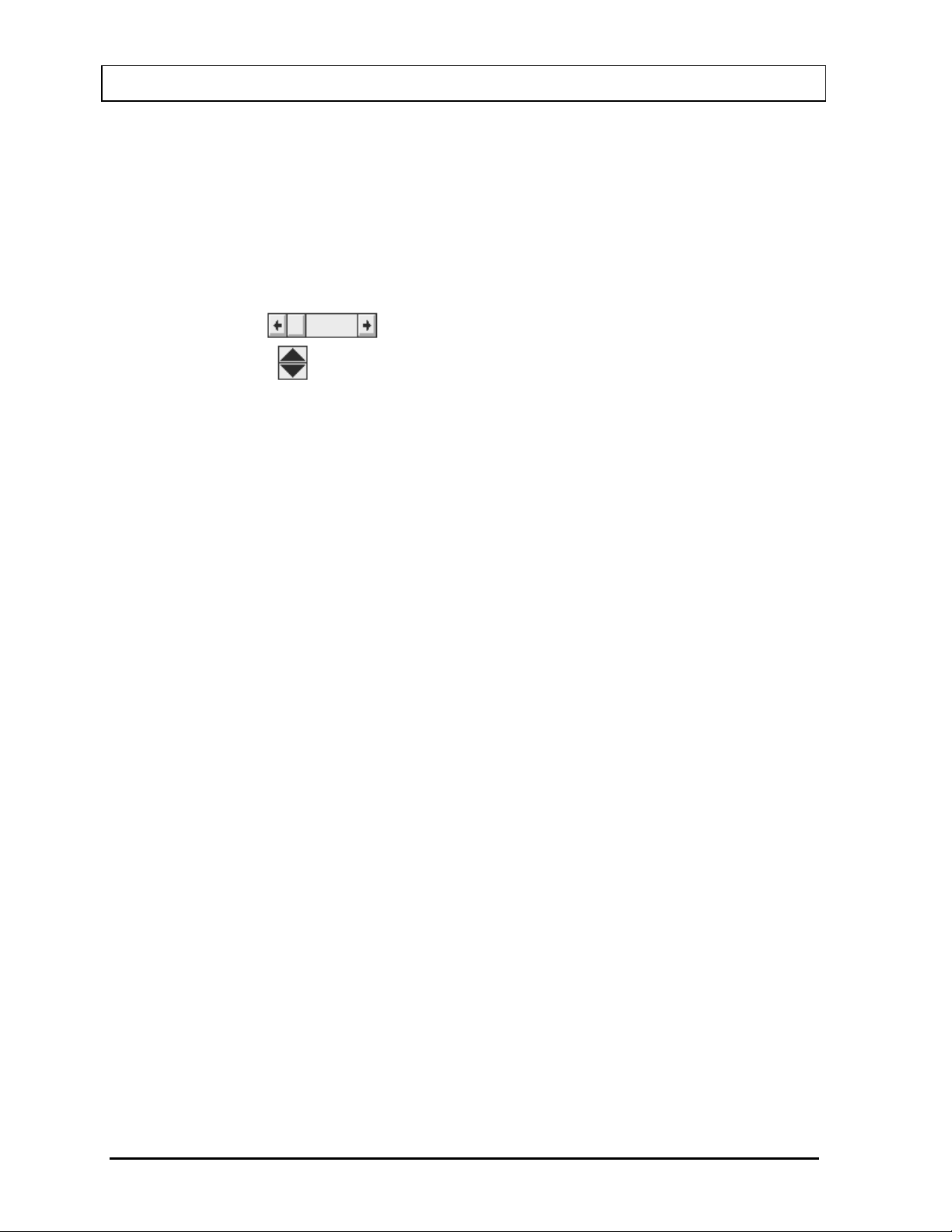
Scroll Bars
Spin Control
................................................................................................... 3-5
..................................................................................... 3-5
List Controls ............................................................................................................ 3-5
Menu Bars ............................................................................................................... 3-6
Icons ....................................................................................................................... 3-6
Keyboard Control .................................................................................................... 3-6
CAPTUS SCREENS ........................................................................................................ 3-7
Typical Test Screen ..................................................................................................... 3-8
Typical Input Screen .................................................................................................... 3-9
Measurement Screen ................................................................................................. 3-10
Add Comments Screen .............................................................................................. 3-11
SHORTCUT KEYS ........................................................................................................ 3-12
All Screens ................................................................................................................. 3-12
Input Screens ............................................................................................................. 3-12
GENERAL SETUP ............................................................................................................. 4-1
INSTALLATION ............................................................................................................... 4-1
ENVIRONMENT REQUIREMENTS ................................................................................. 4-2
Operational .................................................................................................................. 4-2
Storage ........................................................................................................................ 4-2
POWER REQUIREMENTS ............................................................................................. 4-3
Input Power ............................................................................................................. 4-3
Isolation Transformer Output ................................................................................... 4-3
TURN ON PROCEDURE ................................................................................................ 4-3
LOG ON .......................................................................................................................... 4-4
Sign In ......................................................................................................................... 4-4
Sign Off ........................................................................................................................ 4-5
Admin Log On .............................................................................................................. 4-5
User Log On ................................................................................................................ 4-6
ADD USER ...................................................................................................................... 4-7
Add User – Staff Member ............................................................................................. 4-7
Add User – Not a Staff Member ................................................................................... 4-8
CHANGE PASSWORD ................................................................................................... 4-8
LOG ON REPOR T ................................
........................................................................... 4-9
Displaying Selected Us er ........................................................................................... 4-10
Delete User ................................................................................................................ 4-10
Invalidate User ........................................................................................................... 4-10
Revalidate User ......................................................................................................... 4-11
TOC-2 TABLE OF CONTENTS July 14
Page 5

CAPINTEC, INC. CAPTUS® 3000
Displaying Data by Date ............................................................................................ 4-11
Printing Report .......................................................................................................... 4-11
Exiting ....................................................................................................................... 4-11
FIRST TIME STARTUP ................................................................................................ 4-12
System Parameters ................................................................................................... 4-12
Quality Assurance Tests ............................................................................................ 4-14
Reference Pages .................................................................................................. 4-15
Measurement Setups ................................................................................................ 4-15
Reference Pages .................................................................................................. 4-15
NORMAL STARTUP ..................................................................................................... 4-16
QU ALITY AS S U RANC E .................................................................................................... 5-1
INTRODUCTION ............................................................................................................ 5-1
Recommended Routine for CAPTUS
SETTING UP QA PARAMETERS ................................................................................... 5-2
AUTO CALIBRATION ..................................................................................................... 5-5
About Auto Calibration............................................................................................... 5-10
CONSTANCY TEST ..................................................................................................... 5-10
CHI-SQUARE TEST ..................................................................................................... 5-15
MDA TEST .................................................................................................................... 5-19
VIEWING SYSTEM PARAMETERS ............................................................................. 5-22
VIEWING AND PRINTING HISTORY ........................................................................... 5-24
®
3000 System ................................................... 5-1
ISOTOPES ......................................................................................................................... 6-1
INTRODUCTION ............................................................................................................ 6-1
VIEWING AND PRINTING ISOTOPE LIBRARY ............................................................. 6-2
ADDING A NEW ISOTOPE TO THE LIBRARY .............................................................. 6-3
EDITING ISOTOPE INFORMATION ............................................................................... 6-4
DELETING AN ISOTOPE ............................................................................................... 6-5
MEASURING EFFICIENCY ............................................................................................ 6-5
ENTERING EFFICIENCY ............................................................................................... 6-9
THYROID UPTAKE ........................................................................................................... 7-1
INTRODUCTION ............................................................................................................ 7-1
QUICK STEP GUIDE FOR THYROID UPTAKE PROCEDURE ...................................... 7-3
MEASUREMENT PROTOCOLS ................................
..................................................... 7-3
Counting Methods ....................................................................................................... 7-3
Dose Administration .................................................................................................... 7-4
Adding Protocols ......................................................................................................... 7-5
Editing Protocols ......................................................................................................... 7-7
Deleting Protocols ....................................................................................................... 7-8
Printing Protocol Report ............................................................................................ 7-10
PATIENT INFORMATION ............................................................................................. 7-10
Adding Patients ......................................................................................................... 7-10
Viewing Patient Information ....................................................................................... 7-12
Editing Patient Information ........................................................................................ 7-13
Deleting Patient Records ........................................................................................... 7-15
VIEWING AND CHANGING THE SETUP ..................................................................... 7-15
July 14 TABLE OF CONTENTS TOC-3
Page 6

CAPINTEC, INC. CAPTUS® 3000
MAKING MEASUREMENTS ......................................................................................... 7-17
Counting Selected Patient .......................................................................................... 7-19
Administering Dose .................................................................................................... 7-23
RESULTS ...................................................................................................................... 7-24
Patients Reports ........................................................................................................ 7-24
WIPE TESTS ...................................................................................................................... 8-1
INTRODUCTION ............................................................................................................. 8-1
QUICK STEP GUIDE FOR WIPE TEST .......................................................................... 8-3
SETTING UP DEFAULTS ............................................................................................... 8-3
SELECTING ISOTOPES FOR WIPE TEST ..................................................................... 8-4
ADDING WIPE LOCATIONS TO PRESET GROUPS ...................................................... 8-6
ADDING WIPE LOCATIONS TO USER DEFINED GROUPS .......................................... 8-7
EDITING WIPE LOC AT ION INFOR M A TION ................................................................... 8-9
DELETING WIPE TEST LOCATION ............................................................................. 8-10
MAKING MEASUREMENTS ......................................................................................... 8-12
Results ....................................................................................................................... 8-17
VIEWING AND PRINTING RESULTS ........................................................................... 8-18
Search ....................................................................................................................... 8-19
Viewing Wipe Test Data Selectively ...................................................................... 8-21
Selecting Results ................................................................................................... 8-22
Exporting Wipe Test Results ................................................................................. 8-22
Printing Wipe Test Results .................................................................................... 8-23
Exiting Search ....................................................................................................... 8-24
Summary Reports ...................................................................................................... 8-24
Printing Wipe Test Summary Report ..................................................................... 8-29
Exiting Summary Reports ...................................................................................... 8-29
ISOTOPE EFFICIENCY ................................................................................................ 8-29
ABSORBED DOSE ALERT ................................................................................................ 9-1
INTRODUCTION ............................................................................................................. 9-1
Basis for Conversion Calculations ................................................................................ 9-2
MAIN SCREEN ............................................................................................................... 9-2
INCIDENT SETUP ........................................................................................................... 9-4
Setup Incident Parameters ........................................................................................... 9-4
Incident / Site ID ................................
...................................................................... 9-4
Date of Intake .......................................................................................................... 9-4
Select Isotope .......................................................................................................... 9-5
Screening Level ....................................................................................................... 9-5
Counting Parameters Frame ................................................................................... 9-5
Repetitions Frame ................................................................................................... 9-5
New Incident ................................................................................................................ 9-6
Select Incident ............................................................................................................. 9-7
Delete Incident ............................................................................................................. 9-8
Edit Incident ............................................................................................................... 9-10
ADDING PATIENTS ...................................................................................................... 9-11
EDITING PATIENTS ..................................................................................................... 9-14
DELETING PATIENTS .................................................................................................. 9-16
MAKING MEASUREMENTS ......................................................................................... 9-18
TOC-4 TABLE OF CONTENTS July 14
Page 7

CAPINTEC, INC. CAPTUS® 3000
Data Acquisition ........................................................................................................ 9-22
CREATING AN ARCHIVE ............................................................................................. 9-23
OPENING AN ARCHIVE ............................................................................................... 9-24
PATIENT REPORTS .................................................................................................... 9-25
Displaying and Printing .............................................................................................. 9-25
Exporting ................................................................................................................... 9-28
LAB TESTS ..................................................................................................................... 10-1
INTRODUCTION .......................................................................................................... 10-2
SCHILLING TEST ......................................................................................................... 10-3
Setup Counting Parameters ...................................................................................... 10-4
Adding Patients ......................................................................................................... 10-5
Editing Patient Information ........................................................................................ 10-7
Deleting Patient Information ...................................................................................... 10-8
Making Measurements ............................................................................................ 10-10
Data Acquisition .................................................................................................. 10-14
Test Results ............................................................................................................ 10-15
Patients Reports ................................................................................................. 10-15
I 125 BLOOD VOLUME TEST .................................................................................... 10-18
Setup Counting Parameters .................................................................................... 10-19
Adding Patients ....................................................................................................... 10-21
Editing Patient Information ...................................................................................... 10-24
Deleting Patient Information .................................................................................... 10-25
Making Measurements ............................................................................................ 10-26
Test Results ............................................................................................................ 10-30
Patients Reports ................................................................................................. 10-30
Cr51 BLOOD VOLUME TEST ..................................................................................... 10-30
Setup Counting Parameters .................................................................................... 10-31
Adding Patients ....................................................................................................... 10-33
Editing Patient Information ...................................................................................... 10-35
Deleting Patient Information .................................................................................... 10-36
Making Measurements ............................................................................................ 10-38
Test Results ............................................................................................................ 10-42
Patients Reports ................................................................................................. 10-42
RBC SURVIVAL TEST................................
Setup Counting Parameters .................................................................................... 10-43
Adding Patients ....................................................................................................... 10-44
Editing Patient Information ...................................................................................... 10-46
Deleting Patient Information .................................................................................... 10-47
Making Measurements ............................................................................................ 10-48
Test Results ............................................................................................................ 10-51
Patients Reports ................................................................................................. 10-52
................................................................ 10-43
BIOASSAY ...................................................................................................................... 11-1
INTRODUCTION .......................................................................................................... 11-1
BIOASSAY SETUP ....................................................................................................... 11-2
I 131/I 125 and I 123/1 125 Cross Contamination ...................................................... 11-9
ADDING STAFF MEMBERS ......................................................................................... 11-9
EDITING STAFF MEMBER INFORMATIO N ............................................................... 11-11
July 14 TABLE OF CONTENTS TOC-5
Page 8

CAPINTEC, INC. CAPTUS® 3000
DELETING STAFF MEMBER ...................................................................................... 11-11
MAKING MEASUREMENTS ....................................................................................... 11-13
VIEWING AND PRINTING REPORTS ........................................................................ 11-16
TIME ACTIVITY ANALYSIS ............................................................................................. 12-1
INTRODUCTION ........................................................................................................... 12-1
SETTING UP PARAMETERS ........................................................................................ 12-2
MAKING MEASUREMENTS ......................................................................................... 12-5
Saving the Results ..................................................................................................... 12-7
VIEWING PREVIOUSLY SAVED RESULTS ................................................................. 12-9
MCA ................................................................................................................................. 13-1
INTRODUCTION ........................................................................................................... 13-1
ACQUISITION AND COUNT DATA ............................................................................... 13-2
CHANGING DETECTORS ............................................................................................ 13-3
SPECTRUM SCALE & ZOOMING ................................................................................ 13-3
Vertical Zoom ............................................................................................................. 13-3
Horizontal Zoom......................................................................................................... 13-4
Pre-Defined Channel Ranges ................................................................................ 13-4
User Selectable Range .......................................................................................... 13-5
COUNTING SETUP ...................................................................................................... 13-6
SPECTRUM ID (NAME) ................................................................................................ 13-7
REGIONS OF INTEREST (ROI) .................................................................................... 13-8
SAVE AND RESTORE COUNT DATA OR MCA SETTINGS......................................... 13-9
Save Spectrum ........................................................................................................ 13-10
Recall Spectrum....................................................................................................... 13-11
Export to Excel ......................................................................................................... 13-11
Export Raw Spectrum .............................................................................................. 13-12
Save MCA Settings .................................................................................................. 13-12
Recall MCA Settings ................................................................................................ 13-12
Save Counting Setup ............................................................................................... 13-13
Recall Counting Setup ............................................................................................. 13-13
Resto re Curr ent Sett ings .......................................................................................... 13-13
PRINTING MCA DATA ................................................................................................ 13-14
CUSTOMIZING MCA SETTINGS ................................................................................ 13-14
High Voltage ..............
Gain ......................................................................................................................... 13-15
Zero Offset ............................................................................................................... 13-16
Threshold ................................................................................................................. 13-16
MANUAL CALIBRATION ............................................................................................. 13-17
.............................................................................................. 13-15
ARCHIVE .......................................................................................................................... 14-1
INTRODUCTION ........................................................................................................... 14-1
DOING SYSTEM BACKUP (CREATING AN ARCHIVE) ............................................... 14-2
OPENING AN ARCHIVE ............................................................................................... 14-3
VIEWING AND PRINTING RECORDS FROM ARCHIVE .............................................. 14-4
Selecting Tests for Viewing ........................................................................................ 14-4
Viewing or Printing a Record ...................................................................................... 14-5
TOC-6 TABLE OF CONTENTS July 14
Page 9

CAPINTEC, INC. CAPTUS® 3000
Printing All Records in Selected Tests ....................................................................... 14-7
CLEANING AND MAINTEN ANCE ................................................................................... 15-1
INTRODUCTION .......................................................................................................... 15-1
CLEANING and DISINFECTI NG ................................................................................... 15-2
Cleaning Instructions ................................................................................................. 15-2
Disinfecting Instructions ............................................................................................. 15-3
Liner ..................................................................................................................... 15-4
Printer ................................................................................................................... 15-4
PREVENTIVE MAINTENANCE .................................................................................... 15-4
DISPOSAL .................................................................................................................... 15-4
Floor Stand ................................................................................................................ 15-5
Table Top Stand ........................................................................................................ 15-6
SERVICING .................................................................................................................. 15-7
Collimator Block Inspection ....................................................................................... 15-7
Spring-Arm Inspection ............................................................................................... 15-8
Computer Battery Replacement ................................................................................ 15-9
FUSE SERVICING ........................................................................................................ 15-9
Power Line Fuses ...................................................................................................... 15-9
Computer, Monitor and Printer Fuses ...................................................................... 15-10
ACCESSORIES AND REPLACEMENT PARTS ......................................................... 15-10
SHIPPING................................................................................................................... 15-11
CUSTOM PROTOCOLS .................................................................................................. 16-1
INTRODUCTION .......................................................................................................... 16-1
STARTING CUSTOM PROTOCOLS ............................................................................ 16-2
PROTOCOLS ............................................................................................................... 16-3
Adding Protocols ....................................................................................................... 16-3
Viewing Protocols ...................................................................................................... 16-7
Deleting Protocols ..................................................................................................... 16-7
Deleting All Protocols ............................................................................................ 16-7
Selecting the Excel Workbook for the Protocol .......................................................... 16-7
PATIENT DATA ............................................................................................................ 16-8
Adding Patients ......................................................................................................... 16-8
Editing Patient Information ................................
...................................................... 16-10
Deleting Patient Information .................................................................................... 16-10
MAKING MEASUREMENTS ....................................................................................... 16-11
Data Acquisition ...................................................................................................... 16-13
After Counting ......................................................................................................... 16-14
Report ..................................................................................................................... 16-14
CUSTOM PROTOCOLS EXCEL WORKBOOK .......................................................... 16-15
Creating a Workbook for a Protocol (Setup Mode) .................................................. 16-15
Setting Up the Workbook ......................................................................................... 16-18
Protocol Selection ............................................................................................... 16-18
Patient Selection ................................................................................................. 16-19
Entering Formulas .............................................................................................. 16-21
Creating a Report ............................................................................................... 16-22
Viewing Patients from Workbook (User Mode) ........................................................ 16-23
July 14 TABLE OF CONTENTS TOC-7
Page 10

CAPINTEC, INC. CAPTUS® 3000
INDEX
WARRANTY
DECLARATION OF CONFORMITY
TOC-8 TABLE OF CONTENTS July 14
Page 11

CAPINTEC, INC. CAPTUS® 3000
PREFACE
GENERAL ........................................................................................................ 1
SYSTEM DESCRIPTION .................................................................................. 1
MEDICAL EQUIPMENT SAFETY CLASSIFICATION ...................................... 2
ELECTROMAGNETIC INTERFERENCE POTENTIAL .................................... 2
INSTALLATION ............................................................................................... 3
IMPORTANT SAFETY INFORMATION ............................................................ 3
TRADEMARKS ................................................................................................ 3
GENERAL
Thank you for purchasing the Capintec line of Thyroid Uptake Measurement Systems. Every
effor t has been made to ensure that the information in this document is complete, accurate,
and up-to-date. Mention of products manufactured by other companies does not necessarily
constitute endorsement by Capintec, Inc. Capintec assumes no responsibility for the results
of errors beyond its control.
Please address any comments pertaining to this manual to:
CAPINTEC, Inc.
620 Alpha Drive
Pittsburgh, PA 15238
Phone (412) 963-1988
Fax (412) 963-0610
Note: Federal Law restricts this device to sale by or on the order of a physician,
pharmacist or other licensed professional.
SYSTEM DESCRIPTION
Your new CAPTUS® 3000 is available in several configurations. Please take a moment to
review your system to determine exactly the configuration you have received. The basic
Thyroid Uptake System consists of the following:
• Optional Floor Stand or Table Top Stand
• TUS Collimator
• Isolation Transformer
• NaI (sodium iodide) Detector with Detector Socket Base
Note: Two versions of detectors are available: Flat Face or Drilled.
• Computer System with MCA Board installed
November 13 PREFACE P-1
Page 12

CAPINTEC, INC. CAPTUS® 3000
• Standard Computer Monitor or optional Touchscreen Monitor
• Printer
• Cables for connecting detector, printer, etc.
• 15 foot power cord with hospital grade plug
• Software and Documentation
• Windows XP Home or later,
• CAPTUS
®
3000 Manual and Installation Disks or CDs
• Optional Well Counter with drilled Well Detector
MEDICAL EQUIPMENT SAFETY CLASSIFICATION
• CLASS I EQUIPMENT energized from an external power source
• TYPE B EQUIPMENT with applied part (Positioning Rod)
• Ordinary EQUIPMENT without protection against the ingress of water
• Suitable for CONTINUOUS OPERAT ION
• NOT suitable for use in the presence of a an FLAMMABLE ANAESTHETIC
MIXTURE WITH AIR or WITH OXYGEN OR NITROUS OXI DE
ELECTROMAGNETIC INTERFERENCE POTENTIAL
This equipment complies fully with interference immunity requirements of the standard IEC
60601-1-2 “Medical electrical equipment: Part 1: General safety requirements; 2.
Supplementary standard: Electromagnetic compatibility”.
This equipment generates radio frequency energy and, if not installed and used in
accordance with the instructions, may cause harmful interference to nearby devices.
However, there is no guarantee that interference will not occur in a particular installation. If
this equipment does cause harmful interference, the user is encouraged to try to correct the
interference by one of the following measures:
• Increase the separation between the equipment and the affected device.
• Plug the unit into an outlet on a circuit different from that which the affected device is
connected.
If this fails to correct the problem, please contact Capintec’s only Authorized Service Center.
P-2 PREFACE November 13
Page 13

CAPINTEC, INC. CAPTUS® 3000
INSTALLATION
Your system has been shipped from the factory pre-conf igured and fully tested. Installation
consists of placing the components and securing them in place. Detailed installation and
assembly instructions are provided in the included Unpacking and Assembly Instructions
for your system.
IMPORTANT SAFETY INFORMATION
The CAPTUS® 3000 measurement system has been carefully designed to give you years of
safe and reliable performance. As with all electrical equipment, however, there are basic
precautions you must observe to avoid injuring yourself, the patient or damaging the
equipment.
• Follow the unpacking and assembly instructions document, and read this manual
carefully before using this equipment. Be sure to save all provided documents for
future reference.
• Understand all warning and caution labels as explained in the CHAPTER 1:
SAFETY before operating this equipment.
TRADEMARKS
CAPTUS® 3000 and CII are registered trademarks of Capintec, Inc.
Microsoft
Hewlett Packard
®
and MS Windows® are U.S. registered trademarks of the Microsoft Corporation.
®
DeskJet is a registered trademark of the Hewlett Packard Company.
November 13 PREFACE P-3
Page 14

CAPINTEC, INC. CAPTUS® 3000
This page intentionally left blank.
Page 15
CAPINTEC, INC. CAPTUS® 3000
0413
CHAPTER 1
SAFETY
GENERAL ....................................................................................................... 1-1
SYMBOL DEFINITIONS .................................................................................. 1-1
WARNING AND CAUTION LABELS .............................................................. 1-2
CAUTIONS AND NOTES ................................................................................ 1-5
GENERAL SAFETY TIPS ............................................................................... 1-7
GENERAL
These warnings and instructions form an integral part of the CAPTUS® 3000 system and
must be kept available for consultation at all times. Precise compliance with the warnings
and instructions is an essential condition for correct usage and safety of patients and users.
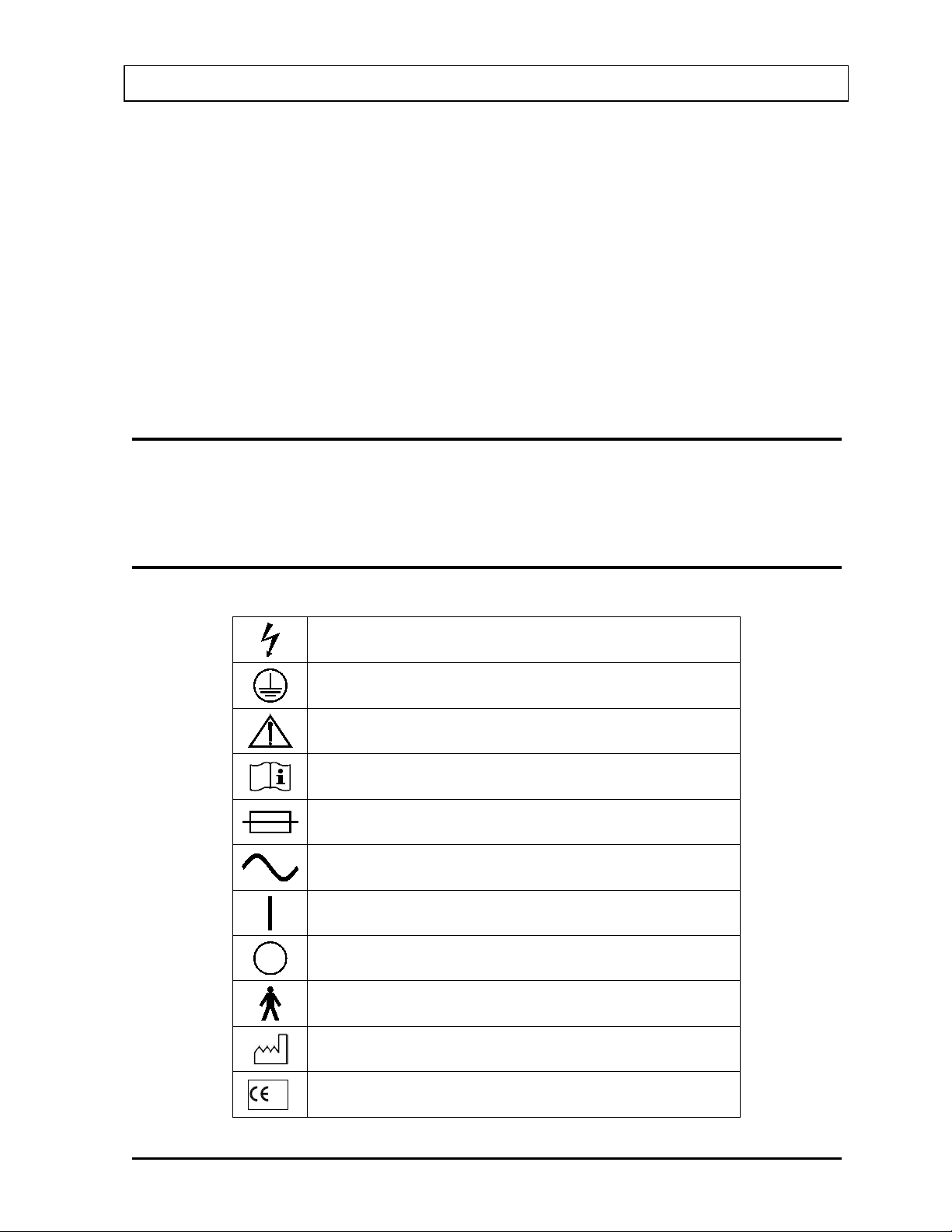
SYMBOL DEFINITIONS
Dangerous Voltage Present
Protective Earth Ground
Caution
Operator should consult a c companying documents
Fuse
AC Voltage
“ON” (power)
“OFF” (power)
Type B Equipment
Date of Manufacture
CE Mark
November 13 SAFETY 1-1
Page 16
CAPINTEC, INC. CAPTUS® 3000
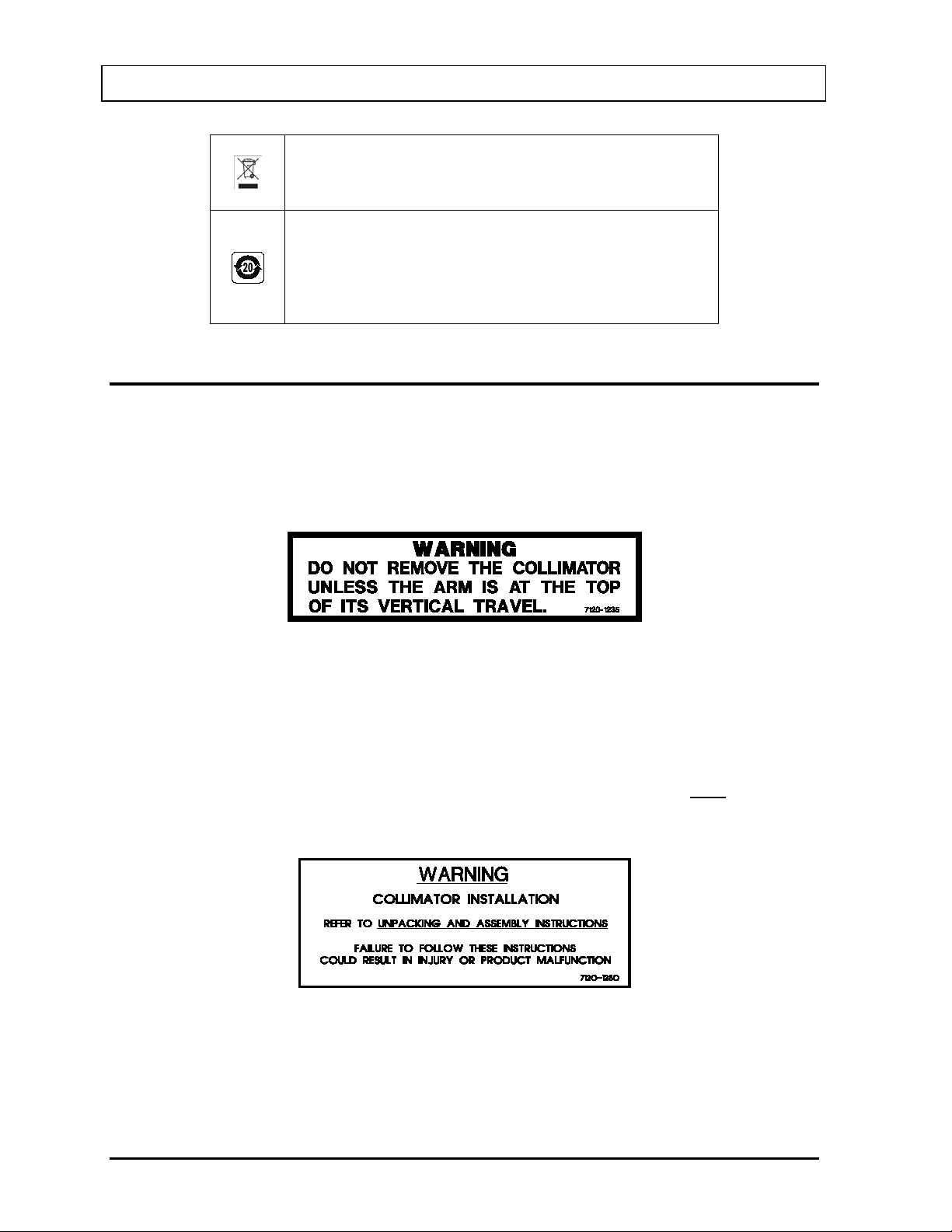
Waste in Electrical and El ect r oni c Equipment (WEEE) –
municipal waste and must be collected sep ar at ely.
Environmentally Friendly Use Period (EFUP) – 20 years
assets.
This symbol indicates that the waste of electrical and
electronic equipment must not be disposed as unsort ed
from the date of manufact ur e – Toxic or hazardous
substances or elements contained in the unit will not leak
or mutate under normal operat in g conditions resulting in
any environmental pollut io n, bodily injury or damage to
WARNING AND CAUTION LABELS
Located in the center section on both sides of the Spring-Arm is a warning label (Figure 1-1)
concerning the hazard of removing the Collimator when the Spring-Arm is in the wrong
position. If the weight of the Collimator is removed from the Spring-Arm, the arm may
forcefully spring upward causing serious injury to the operator. The Spring-Arm must be fully
extended in the upright position to prevent this from happening.
Figure 1-1
Located in the front section on both sides of the Spring-Arm is a warning label (Figure 1-2
)
concerning the hazard of improperly installing the Collimator onto the Spring-Arm. If the
Collimator Support Pin is not fully inserted and latched into the Receptacle Block of the
Spring-Arm, the Collimator may detach from the Spring-Arm and fall onto the patient. In
addition, the arm can forcefully swing upward and cause serious injury to the operator. The
Collimator is safely installed on the Spring-Arm when the red warning ring is NOT visible
between the Collimator and the Receptacle Block. Refer to the UNPACKING AND
ASSEMBLY INSTRUCTIONS fo r illus trations.
Figure 1-2
Located on the top right side of the Computer case is a label (Figure 1-3) containing three
caution statements pertaining to electrical safety of the Computer. They are as follows:
1-2 SAFETY November 13
Page 17

CAPINTEC, INC. CAPTUS® 3000
• TO REDUCE THE RISK OF ELECTRIC SHOCK, DO NOT REMOVE COVERS –
This statement is necessary because of the high voltage present (1000 volts) on the
PC board installed in the computer. A screwdriver is necessary to remove the covers.
• REFER SERVICING TO QUALIFIED SERVICE PERSONNEL – This statement
informs the user that no servicing of the computer system should be performed by the
user.
• ALL POWER CABLES MUST BE CONNECTED THROUGH THE ISOLATION
TRANSFORMER – This statement is necessary to eliminate any shock hazard to the
patient and the user.
Figure 1-3
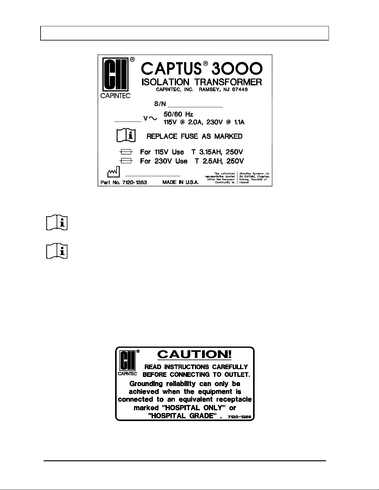
Located on the top of the Isolation Transformer is a label (Figure 1-4) providing the system
power requirements, the voltage and serial number of the system, the replacement fuse
values for both power line voltages and the fuse replacement warning.
November 13 SAFETY 1-3
Page 18
CAPINTEC, INC. CAPTUS® 3000
An Eczacibasi-Monrol company
CAUTION: Please reference CHAPTER 15: CLEANING AND MAINTENANCE
Transformer.
Figure 1-4
for instructions on how to change the fuses of the Isolation
CAUTION: A fire hazard may exist if the wrong size of fuse is installed.
Located on the left side of the Isolation Transformer is a label (Figure 1-5) with two caution
statements pertaining to the main power cord of the Isolation Transformer:
• READ INSTRUCTIONS CAREFULLY BEFORE CO NNECTING TO OUTLET – This
statement directs the user to the Owner's Manual before connecting the power.
• “HOSPITAL ONLY” or “HOSPITAL GRADE” – This statement alerts the user to
select an electrical power receptacle that is designated as such, to ensure reliable
grounding to the CAPTUS
®
system.
Figure 1-5
1-4 SAFETY November 13
Page 19
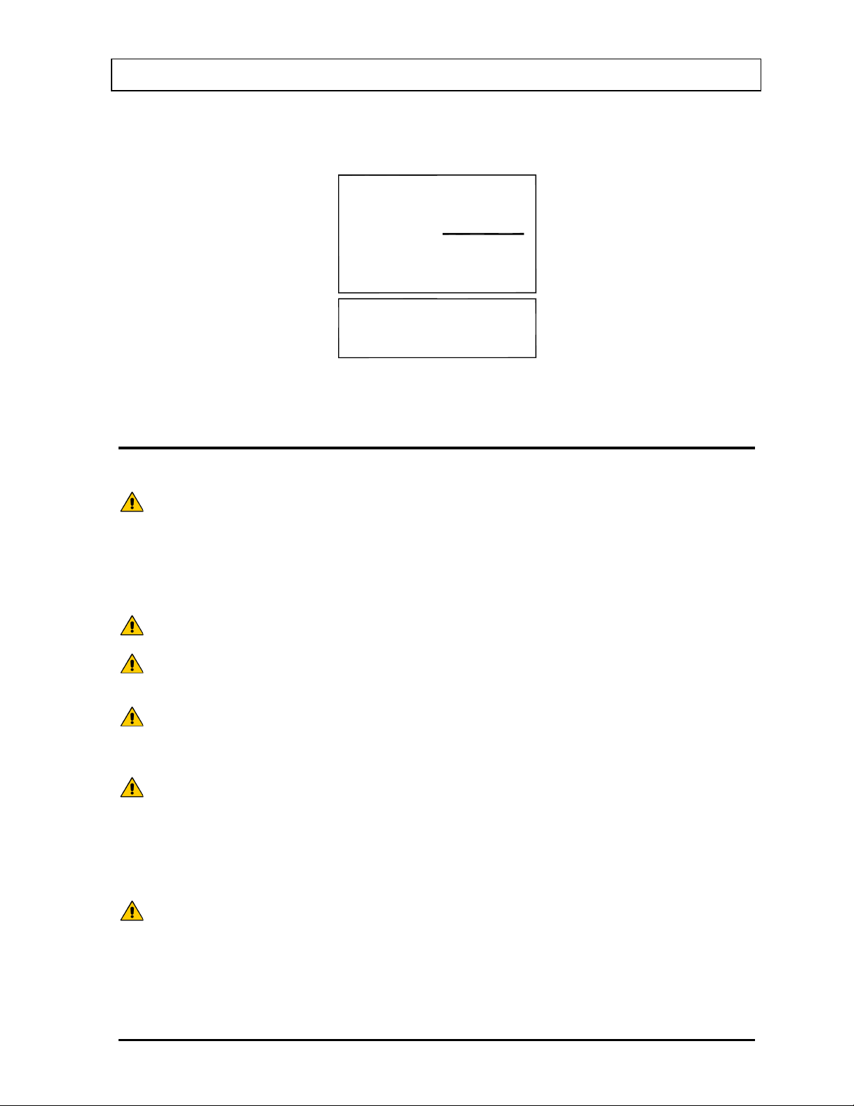
CAPINTEC, INC. CAPTUS® 3000
POWER
CORD
COMPUTER
POWER
PRINTER
CORD
CORD
POWER
MONITOR
50/60 Hz
115V @ 0.7A
50/60 Hz
115V @ 1.9A
COMBINED
CAUTION: Changing the date or time while a timed test is in progress (for example,
adjust clock for daylight saving changes” checkbox is not checked.
CAUTION: Only qualified/trained personnel should operate or service this unit.
CAUTION: If the equipment is used in a manner not specified in this manual, the
protection provided by the equipment may be impaired.
CAUTION: High voltage is present inside the Detectors (up to 1000 Volts). Due to
plugged in may be hazardous. Refer all servicing to qualified personnel.
CAUTION: There are no internal adjustments inside the detector, computer or
personnel.
CAUTION: Never use the Well Detector without the well liner in place. Liners are
operating.
Located by each line cord on the Isolation Transformer are labels (Figure 1-6) indicating
which device each cord is to be connected to and the power availability for that device.
Figure 1-6
CAUTIONS AND NOTES
a 24 hour Thyroid Uptake Test) might affect the results or introduce
unexpected error. Care should be taken to evaluate any potential impact
for ongoing tests before changing the date or time. Verify that in the Date
and Time Properties in Windows Control Panel that the “Automatically
the presence of this high voltage, opening the covers with the system
printer that should be performed by the user within the conditions of the
warranty, except for changing the Isolation Transformer fuse. Due to the
presence of high voltages, opening the cover of the computer with the
system plugged in may be hazardous. Refer all servicing to qualified
November 13 SAFETY 1-5
inexpensive and easy to replace. A contaminated detector is a very
costly mistake. If unit becomes contaminated remove liner and clean unit
as stated in CHAPTER 15: CLEANING AND MAINTENANCE before
Page 20

CAPINTEC, INC. CAPTUS® 3000
CAUTION: Care must be exercised when moving the system or when maintenance
may tip over.
CAUTION: Verify that the collimator is correctly installed as stated in the
instructions could result in injury or product malfunction.
CAUTION: This equipment generates radio frequency energy and is susceptible to
installation/location.
CAUTION: If any Computer, Monitor, Printer or cables other than the model supplied
become susceptible to EMI.
CAUTION: If any other detectors than those supplied by Capintec is used, the safety
general area as the CAPTUS® 3000 may become susceptible to EMI.
CAUTION: If any components are used other than those supplied by Capintec, the
compromised.
CAUTION: The equipment should not be used adjacent to or stacked with other
configuration in which it will be used.
CAUTION: Do not disconnect or connect detectors from the computer, while the
system is on. Shut down the computer first.
CAUTION: The unit contains lead. The unit should be disposed of in accordance
with local and national regulations.
CAUTION: The unit contains a lithium battery. This should be disposed of in
accordance with local and national regulations.
CAUTION: The user should always verify the validity of any measurement or test
result in order to minimize measurement errors.
is performed. If the system is inclined at more than a 15-degree angle, it
UNPACKING AND ASSEMBLY INSTRUCTIO NS . Failure to follow these
radio frequency energy (such as from other equipment and portable and
mobile RF communications equipment). The equipment needs to be
installed and used accordingly with these instructions; otherwise the
equipment may not function properly or may cause harmful
Electromagnetic Interference (EMI) to nearby devices. There is,
however, no guarantee that interference will not occur in a particular
by Capintec is used, the safety of the unit may be compromised or other
devices located in the same general area as the CAPTUS
®
3000 may
of the unit may be compromised or other devices located in the same
power and signal connections must be the same as those for the original
manufacturer’s configuration or the safety of the unit may be
equipment and that if adjacent or stacked use is necessary, the
equipment should be observed to verify normal operation in the
1-6 SAFETY November 13
Page 21

CAPINTEC, INC. CAPTUS® 3000
CAUTION: To remove main power from the system, the Isolation Transformer power
cable must be unplugged from the medical grade wall socket.
Note: It is recommended that periodic (every five years) re-calibration of the unit be
performed only by Capintec’s Authorized Service Center (reference CHAPTER 15:
CLEANING AND MAINTENANCE) to guarantee that the instrument's high reliability is
maintained).
GENERAL SAFETY TIPS
• Unplug the equipment before cleaning it. Use only a damp cloth; do not use solvents
or aerosol cleaners.
• To protect the equipment from overheating, make sure none of the openings (vents)
on the computer, monitor or the printer are blocked.
• Do not use the equipment directly in front of a radiator, heat register or air
conditioning duct.
• Do not use the equipment near water or spill liquids of any kind into the equipment.
• Be sure that your power source matches the rating listed on the Isolation
Transformer.
• The CAPTUS
®
3000 power cord has a grounded, 3-prong plug as a safety feature,
and it will only fit into a grounded outlet. Do not use an adapter to defeat the
grounding.
• The CAPTUS
®
3000 computer system is connected to the Isolation Transformer to
comply with electrical safety for Medical Electrical Equipment.
• Due to the risk of electrical shock, do not install or use a modem or a network adapter
with the CAPTUS
®
3000 computer system.
• To avoid damaging the power cord, do not place anything on it or place it where it will
be walked on. If the cord becomes damaged, replace it immediately.
• Aside from the routine maintenance described in this manual, do not try to service
this equipment yourself. There are no user serviceable parts contained in the system
other than the fuses in the Isolation Transformer. Do not make any adjustments other
than those outlined in this manual, as you may in-validate the calibration or cause
damage requiring extensive repair work. Refer servicing to qualified service
personnel.
• Do not subject the detectors to rough handling, or rapid temperature changes, as the
NaI Scintillation Crystal can be damaged.
November 13 SAFETY 1-7
Page 22

CAPINTEC, INC. CAPTUS® 3000
This page intentionally left blank.
Page 23

CAPINTEC, INC. CAPTUS® 3000
CHAPTER 2
FUNCTIONAL & TECHNICAL
DESCRIPTION
INTENDED USE .............................................................................................. 2-1
OPERATOR PROFILE .................................................................................... 2-2
OPERATOR TRAINING .................................................................................. 2-2
FUNCTIONAL DESCRIPTION ........................................................................ 2-2
Thyroid Uptake ........................................................................................... 2-2
Wipe Test .................................................................................................... 2-3
Lab Tests .................................................................................................... 2-3
Bioassay ..................................................................................................... 2-4
TECHNICAL DESCRIPTIO N ........................................................................... 2-4
Detector ...................................................................................................... 2-4
Multichannel Analyzer ................................................................................ 2-5
TECHNICAL SPECIFICATIONS ..................................................................... 2-6
System Hardware ....................................................................................... 2-6
Environment Requirements ....................................................................... 2-8
Warm Up Period ......................................................................................... 2-9
System Power Requirements .................................................................... 2-9
Regulatory Listings ................................................................................... 2-10
INTENDED USE
The CAPTUS® 3000 Thyroid Uptake / Well System is intended to be used by trained Nuclear
Medicine Technologists for performing Thyroid Uptake, Thyroid Bioassay, Wipe Test, Blood
Volume (with Cr-51 or I-125) Test, Schillings Test and RBC Survival Test.
Also using the system are Health Physicists with expertise in nuclear medicine and radiation
safety – typically used for assessing reproducibility of counting instruments with various
Quality Assurance procedures (Chi-Square, Linearity, Constancy, Accuracy, etc.).
The CAPTUS
decay corrections, efficiency calculations and maintains a database for storage and easy
retrieval of patient demographic data and measurement results.
July 14 FUNCTIONAL & TECHNICAL DESCRIPTION 2-1
®
3000 also performs Pulse Height Analysis, isotope identification, radioisotope
Page 24

CAPINTEC, INC. CAPTUS® 3000
OPERATOR PROFILE
The operator profile for the Nuclear Medicine Technologists, Physicians and Health
physicists is as follows:
• Education:
o Minimum: at least an Associate Degree
o No maximum
• Knowledge:
o Minimum: Understands the basic concepts of nuclear medicine.
o No maximum
• Language Understanding:
o English
o Other languages are available for instructions for use
• Experience:
o Minimum: Has minimum training or is under surveillance by a trained user.
o No maximum
OPERATOR TRAINING
This Owner’s Manual contains all of the information required to operate the CAPTUS® 3000.
FUNCTIONAL DESCRIPTION
Thyroid Uptake
Thyroid uptake is a measurement of the ratio of the amount of radioactive material
concentrated in the thyroid gland to the amount of radioactive material administered to the
patient. Thyroid uptake measurements are generally used to determine conditions of
hyperthyroidism. High uptake results are found in Graves disease, toxic nodular goiter, and
stimulator secreting tumors or can be TSH-induced. Low uptake results are found with
thyroid hormone secretion in ectopic tumors, hormonal release in thyroid injury, after intake
of thyroid hormone, or in Jod-Basedow disease. During the treatment of thyroid cancer by I131 ablation, uptake measurements are used to monitor thyroid activity.
The CAPTUS
data for both the administered dosage and the patient, decay correct all count data, calculate
thyroid uptake results, and store all of this information in the thyroid uptake database.
Regions of Interest have been defined for three isotopes, I-131, I-123, or Tc-99m. If normal
values have been entered, results exceeding these values will be flagged. All of the patient
information may be printed. The thyroid uptake software has been designed to accommodate
a variety of different counting protocols, using either capsules or liquid dosages.
®
3000 system will store patient demographic and dosage information, count
2-2 FUNCTIONAL & TECHNICAL DESCRIPTION July 14
Page 25

CAPINTEC, INC. CAPTUS® 3000
Wipe Test
The Wipe Test measures radioactive contamination for nuclear medicine departments and
laboratories, as mandated by state and federal radiation safet y requirements .
Note: A Drilled Probe for the Collimator or an optional external Well Counter is required for
Wipe measurements.
Lab Tests
Urine Tests
Schilling Test
The Schilling Test utilizes Cobalt 57 labeled Vitamin 12 and is used to determine B12 deficiencies from either malabsorption, lack of intrinsic factor (pernicious anemia),
or intraintestinal destruction. The test entails collection of urine for 24 or 48 hours
after the oral administration of radioactive labeled vitamin B-12. The ratio of excreted
to administered Co57 is calculated. If the initial results indicate a reduced amount of
excreted vitamin, the test is repeated with a second sample of labeled B-12 and
intrinsic factor. For Schilling Test I, abnormal results are generally less than 8%-10%.
Normal range is generally 11% to 26%. For Schilling Test II, no change indicates
malabsorption, while an improved percentage indicates pernicious anemia.
Blood Tests
Blood Volume Tests
Blood Volume determinations involving radioactive tagging are most frequently used
in specific disease conditions when the hematocrit may not accurately estimate true
blood volume. Such conditions include extensive trauma or burn patients, certain
types of anemia, and polycythemia. Most frequently used radioactive tracers are
protein labeled I125 for plasma measurements and Cr51 tagged RBCs for red cell
mass determinations.
RBC Survival Test
RBC survival determination involving radioactive tagging is most frequently used in
diagnosis of hemolytic anemia. The CAPTUS
parameters follow the testing protocol outlined in the Mallinckrodt RBC Survival
Instructions that utilize Sodium Chromate Cr51 Injections. The software standardizes
the 24-hour sample to 100% survival, and automatically decay corrects each
subsequent sample. This permits the user to measure each sample as soon as it is
collected. For this reason, all sample volumes must be the same. Each sample must
also have a hematocrit (HCT) measurement. The subsequent samples are corrected
for any differences in hematocrit.
®
3000 software and default counting
July 14 FUNCTIONAL & TECHNICAL DESCRIPTION 2-3
Page 26

CAPINTEC, INC. CAPTUS® 3000
Bioassay
All staff members who work with Iodine-131, Iodine-125, or Iodine-123 need to have regular
Bioassay measurements taken to monitor exposure levels. Most state and federal radiation
safety regulations mandate that these thyroid measurements be taken periodically.
The CAPTUS
®
3000 uses one bioassay protocol, which is user-defined. Before performing
bioassay measurements on the staff, the staff member names and ID numbers should be
added to the database and parameters for the bioassay protocol should be set up.
TECHNICAL DESCRIPTION
The CAPTUS® 3000 is a PC based application running on the Windows® operating system.
The basic Thyroid Uptake system consists of the following:
• Optional Floor Stand or Table Top Stand
• TUS Collimator
• Isolation Transformer
• NaI (sodium iodide) Detector with Detector Socket Base
Note: Two versions of detectors are available: Flat Face or Drilled.
• Computer System with hardware installed to switch inputs, amplify / calibrate the
signal, and perform multi-channel analysis
• Standard Computer Monitor (or optional Touchscreen Monitor)
• Printer
• Cables for connecting detector, printer, etc.
• 15 foot power cord with hospital grade plug
• Software and Documentation
• Windows XP Home or later,
• CAPTUS
• Optional Well Counter with drilled Well Detector
Detector
The CAPTUS
Iodide) crystal and photomultiplier tube detector assemblies, a 1024 channel MCA
(Multichannel Analyzer), along with associated electronics and electronic controls which
provide power and amplification of the pulses generated by the detectors, as well as software
modules which record, analyze, manipulate, and store the measured data.
Since NaI crystals are hygroscopic, the detector assemblies are hermetically sealed with an
aluminum coating. If the seal is broken, then water will be absorbed by the crystal, causing
deterioration of its measurement capabilities, and eventually it will require replacement. For
this reason, always handle the detector with care. Avoid scratching the surface with metal
objects such as pens.
®
3000 Manual and Installation Disks or CDs
®
3000 system is equipped with one or two NaI (Tl) (Thallium-activated Sodium
2-4 FUNCTIONAL & TECHNICAL DESCRIPTION July 14
Page 27

CAPINTEC, INC. CAPTUS® 3000
When a gamma or x-ray fr om a radioactive source reaches the NaI crystal, it collides with the
electrons in the crystal matrix and transfers energy, primarily through Compton interaction.
The excited electron releases this energy as visible light in direct proportion to its absorbed
energy. For this reason, NaI detectors are classified as scintillation detectors. The higher the
energy of the incident ray, the more Compton collisions and consequently the more visible
light emissions will be measured before all of the energy is absorbed. These sequential
emissions of light for each incident ray generated from the sequential Compton collisions
appear to the measuring system as a single light pulse. The intensity of the pulse is directly
proportional to the energy of the incident gamma or x-ray. The light is eventually directed
toward the photomultiplier tube, either by the direction in which it was emitted or by reflection
from the interior of the aluminum housing. The photomultiplier tube, which is optically
connected to the sodium iodide crystal, converts the visible light pulses into electrical energy
and amplifies the signal through a series of dynodes. The resultant electrical signal is directly
proportional to the intensity of the incident light pulse. Therefore, the pulse height generated
by the system is directly proportional to the energy of the incident gamma or x-ray detected
by the system.
Multichannel Analyzer
A multichannel analyzer records the number and height of the electrical pulses generated by
the system, divides the pulses into groups based upon pulse height, and provides a visible
picture or spectrum of the pulses as well as count information. The CAPTUS
®
3000 divides
the pulses into 1024 groups or channels. Since pulse height is directly related to the energy
of the incident photon, the spectrum displays the pulse heights as a graph of pulses or
counts on the vertical scale and energy on the horizontal scale. By matching the displayed
spectrum to the decay scheme of an isotope, positive identification of the radioactive source
can be achieved.
Electronics associated with the process include the high voltage power supply, amplifiers,
and gain adjustments. The high voltage power supply provides voltage to the photomultiplier
tube for the light to electrical impulse conversion and amplification process. The amplifiers
linearly amplify the electrical signal produced by the photomultiplier tube before the signal is
passed to the MCA. The pulse height remains proportional to the energy of the incident ray.
The gain controls the amount of amplification that is performed by the card, and is adjustable
by the user.
The spectral display also has adjustments which control the pulse height that include zero
adjust and lower level discriminators (threshold). The zero adjust controls the channel used
for 0 pulse height or 0 energy. The threshold sets the limit for the lowest pulse height to be
analyzed.
July 14 FUNCTIONAL & TECHNICAL DESCRIPTION 2-5
Page 28

CAPINTEC, INC. CAPTUS® 3000
TECHNICAL SPECIFICATIONS
System Hardware
Detectors, Data Acquisition, and Computer
®
Pentium class computer system including the MS Windows
dual input Multichannel Analyzer PC Board, two scintillation detectors, a mouse or
trackball pointing device, a color printer, and an easy to use CAPTUS
application software.
Floor Stand
Rugged Floor Stand with heavy duty locking casters and an articulating arm for the
positioning of the Detector/Collimator. Individual shelves are provided for the
CAPTUS
®
3000 computer system (monitor, keyboard and mouse or trackball) and the
printer. Mounting for the Isolation Transformer and the optional Well Detector is
provided at the base of the Floor Stand.
Dimensions:
Height ....................... 175.3 cm ....... (69”)
Width ........................ 71.1 cm ......... (28”)
Depth ........................ 78.7 cm ......... (31”)
Weight ...................... 181.8 kg ........ (400 lb.)
(with optional well) .... 213.6 kg ........ (462 lb.)
Table Top Stand (optional)
An excellent alternative to the Floor Stand when space is at a premium, the Table
Top Stand allows for positioning of the Detector/Collimator and is very stable when
placed on a sturdy table or bench, yet the unit may be easily moved to another
location when desired.
Dimensions:
Height ....................... 37.1 cm ......... (14.6”)
Width ........................ 25.4 cm ......... (10”)
Depth ........................ 25.4 cm ......... (10”)
Weight ...................... 3.7 kg ............ (8.1 lb.)
Isolation Transformer
An Isolation Transformer is provided with the CAPTUS
the leakage current meets IEC 60601-1 3
rd
Edition Medical Equipment Safety
Standard. A detachable 4.6m (15 ft) power cord, with a hospital grade plug, is
provided to connect the Isolation Transformer to the power source. Dual power line
fuses are provided at the power entry module for quick replacement.
operating system with a
®
3000
®
3000 system to ensure that
2-6 FUNCTIONAL & TECHNICAL DESCRIPTION July 14
Page 29

CAPINTEC, INC. CAPTUS® 3000
Dimensions:
Height ........................ 13.3 cm .......... (5.25”)
Width ......................... 17.5 cm .......... (6.88”)
Depth ........................ 10.9 cm .......... (4.31”)
Printer
HP Officejet 6000 seri es Inkjet (or equivalent) – inkjet color printer, prints results of
studies including graphic displays.
Computer System (Minimum System Requirements)
PC compatible, Pentium II / 400 MHz CPU
1 open PCIe Expansion Slot
CD-ROM Drive
500MB free Hard Drive space
128MB RAM
SVGA Graphics Card (800×600, 24 bit Color)
SVGA 14” Color Monitor
Keyboard and Mouse / Trackball
MS Windows
MCA Interface PC Board
1024 Channels
Maximum Count Rate 100,000 cps
ROI's – Automatic or Manual
QA automatic – gain adjust, energy calibration, resolution, chi-squared, constancy
Automatic efficiency calculation and storage
Adjustable Lower Level Discriminator (Threshold)
Differential Nonlinearity <2% over the top 98% of channels
Integral Nonlinearity <1% over the top 98% of channels
Adjustable Zero
Preset Live Time, Real Time, Total Counts
Automatic Peak Finding
PCIe x1
Detector Inputs
Software control of detector selection
SHV connectors for TUS Probe and Well Detectors
CAPTUS
Stores and prints all test data results
Reference library for isotopes
User definable normal ranges on printout
®
98
®
3000 Software Package
July 14 FUNCTIONAL & TECHNICAL DESCRIPTION 2-7
Page 30

CAPINTEC, INC. CAPTUS® 3000
Thyroid Uptake
Wipe Test
Schilling Test
Blood Volume
RBC Survival
MCA
TUS Probe Detector
NaI(TI) flat face crystal / PM Tube: ... 5.1 x 5.1 cm ... (2” x 2”)
Monoline construction
Resolution (Full Width-Half Max) – ≤9.5% or better for Cs137
Lead Shielded Collimator
Complies with ANSI Standard N44.3-1973
10 ft. (maximum) coaxial signal/high voltage cable
Well Detector – Optional
With attached 10 ft. (maximum) coaxial signal/high voltage cable. (Allows for the
placement of the Well away fr om the Stand.)
NaI(TI) well type crystal / PM Tube: .. 5.1 x 5.1 cm ... (2” x 2”)
Well diameter: ....................... 1.6 cm ............ (0.625”)
Well depth: ............................ 4 cm ............... (1.5”)
Monoline construction
Resolution (Full Width-Half Max) – ≤10.0% or better for Cs137
Lead shielding – lined with brass (0.16 cm (1/16”) thick) to minimize backscatter
Thickness:............................. 2.5 cm ............ (1”)
Height: .................................. 32.5 cm .......... (12.8”)
Diameter: .............................. 11.4 cm .......... (4.5”)
Weight: ................................. 27.9 kg ........... (61.4 lb.)
Environment Requirements
Operational
The instrument should be located where the level of the background radiation is as
low and as constant as possible.
The instrument should be located where the temperature is stable within a range of
+50°F to +85°F (+10°C to +30°C) and the maximum relative humidity is 90% noncondensing for maximum reliability and accuracy.
The instrument should be located where the barometric pressure is within a range of
27–31 inches of mercury (91–105 kilopascals).
2-8 FUNCTIONAL & TECHNICAL DESCRIPTION July 14
Page 31
CAPINTEC, INC. CAPTUS® 3000
CAUTION: If these environmental requirements are not followed, the instrument may
display erroneous readings
CAUTION: If the input voltage to the following items is not within the stated
Storage
The instrument should be stored where the temperature is stable and the range is
from +39°F to +110°F (+4°C to +43°C) and the maximum relative humidity is 90%
non-condensing for maximum reliability.
The instrument should be stored where the barometric pressure is within a range of
15–33 inches of mercury (51–112 kilopascals).
Warm Up Period
Approximately 30 minutes should be allowed for the instrument to stabilize. While the
instrument is warming up, it is strongly recommended that you become familiar with the
CAPTUS
System Power Requirements
®
3000.
limits, the unit may not function correctly or may be damaged
Input Power
Line Voltage: ............. 115 or 230 Vac depending on model ordered
Line Frequency: ........ 60 or 50 Hz
Current: ..................... 2.0 Ampere @ 115V
1.1 Ampere @ 230V
Fuse: For 115V use T 3.15AH, 250V, (Time Delay)
For 230V use T 2.5AH, 250V, (Time Delay)
Isolation Transformer Output
Computer and Monitor combined
Output Vo ltage: ......... 115Vac
Current Output: ......... 1.9A
Frequency: ................ 50/60Hz
Printer
Output Voltage: ......... 115Vac
Current Output: ......... 0.7A
Frequency: ................ 50/60Hz
Printer
HP Officejet 6000 Series (or equivalent) Printer (optional)
100-240Vac, 50/60Hz, 1.5A
July 14 FUNCTIONAL & TECHNICAL DESCRIPTION 2-9
Page 32

CAPINTEC, INC. CAPTUS® 3000
Regulatory Listings
®
The CAPTUS
the following Standards:
EMC
Safety
3000 has been independently tested and is manufactured in compliance with
• IEC 60601-1-2 (2007): Medical Electrical Equipment – Part 1 General
Requirements for Safety – Section 1.2 Collateral Standard: Electromagnetic
Compatibility – Requirements and Tests
• AAMI ES60601-1 Issued: 2005: Medical electrical equipment Part 1: General
requirements for basic safety and essential performance
• CAN.CSA-C22.2 No. 60601-1:08: Medical electrical equipment – Part 1:
General requirements for basic safety and essential performance
• IEC 60601-1 Issued: 2005 Ed:3: Medical electrical equipment Part 1: General
requirements for basic safety and essential performance
• IEC 60601-1-6 2010 3
rd
Edition: Medical electrical equipment – Part 1-6:
General requirements for basic safety and essential performance – Collateral
Standard: Usability
2-10 FUNCTIONAL & TECHNICAL DESCRIPTION July 14
Page 33

CAPINTEC, INC. CAPTUS® 3000
CHAPTER 3
GENERAL OPERATI NG INSTRUCTIONS
INTRODUCTION ............................................................................................. 3-1
WINDOWS OPE RATING CONVEN TIONS ...................................................... 3-1
Common Controls and Techniques .......................................................... 3-1
Windows Controls ...................................................................................... 3-2
CAPTUS SCREENS ........................................................................................ 3-7
Typical Test Screen .................................................................................... 3-8
Typical Input Screen .................................................................................. 3-9
Measurement Screen ................................................................................ 3-10
Add Comments Screen ............................................................................. 3-11
SHORTCUT KEYS ......................................................................................... 3-12
All Screens ................................................................................................. 3-12
Input Screens ............................................................................................ 3-12
INTRODUCTION
The CAPTUS® 3000 software runs on the Microsoft Windows® operating system and follows
standard Windows interface conventions. If you are familiar with running Windows based
programs, then you should find the CAPTUS
program. If you have never used a Windows based program before, please read the next
section in this chapter carefully. Windows uses very consistent techniques for user
interaction. These techniques are visual and generally oriented toward use of a pointing
device, such as a mouse or trackball. In most cases there are alternate keyboard techniques
for accomplishing the same task.
Note: If your system includes the optional Touchscreen Monitor, the following are replaced
with the related action for the Touchscreen:
• The pointing device – Finger or Stylus
• Clicking an item with the pointing device – Touch the item with a Finger or Stylus
®
3000 a very user friendly and easy to use
WINDOWS OPERATING CONVENTIONS
Common Controls and Techniques
®
The CAPTUS
performed will consist of one or more dialog boxes, as shown in Figure 3-1. Each screen will
have various controls on it, which perform functions when clicked with the pointing device or
when selected from the keyboard. When you are finished with all of the tasks on a given
3000, like all Windows based programs, is task oriented. Each task to be
screen, selecting the
November 13 GENERAL OPERATING INSTRUCTIONS 3-1
or button will return you to the previous screen.
Page 34
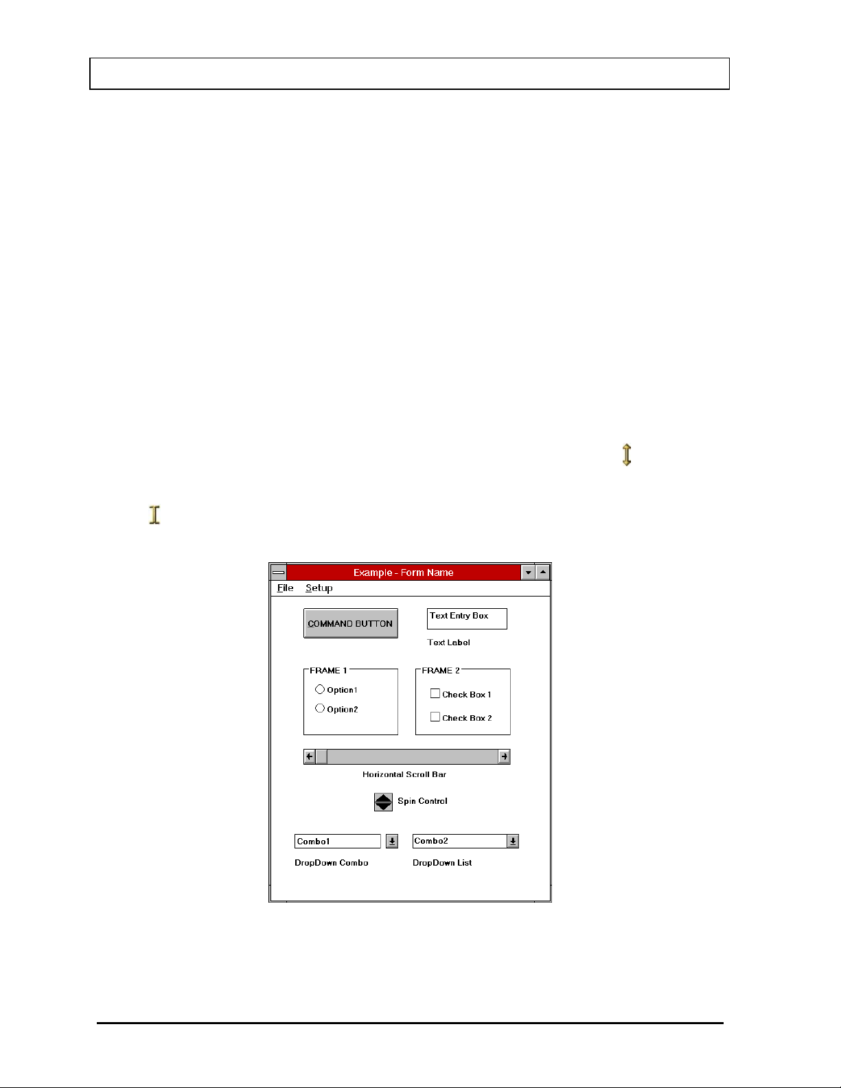
CAPINTEC, INC. CAPTUS® 3000
Windows Controls
The most common Windows controls are described below. When controls are selected they
cause functions or actions to be performed. A control can be selected in several ways; the
most common way is with the pointing device. Positioning the pointing device cursor over the
control and clicking the left pointing device button selects the control. The pointing device
cursor takes several different shapes depending on what is going on in the program and
where it is on the screen. Most controls can also be selected through the keyboard. The Tab
key on the keyboard is used to move from one control to another. Pressing Shift+Tab will
move back one control. Once a control is selected it can be activated, or changed with other
keys. The specific keys that affect each type of control are discussed below.
Pointing Device Cursor
The pointing device cursor is used to select items on the screen. Most of the time the
cursor appears as an arrow with a black outline filled with white. When the system is
busy doing something that will prohibit it from responding, the cursor changes to an
hourglass. When in MCA mode and the cursor is within the boundaries of the
spectrum display, the cursor changes to a double-ended vertical arrow
.
When the cursor is hovered over a text box, it will change to a thin vertical “I-beam”
. Note that actually having the ability to input or edit requires that you click the
pointing device button to cause the edit cursor, a blinking vertical line, to appear.
Figure 3-1
3-2 GENERAL OPERATING INSTRUCTIONS November 13
Page 35

CAPINTEC, INC. CAPTUS® 3000
Command Button
®
The most common control in the CAPTUS
3000 is the command button, for example
the
command button. A command button can be activated in one of three
ways:
• positioning the pointing device over the button and clicking the pointing
device's left button once,
• using the Tab key on the keyboard to move the highlight from control to
control until the desired control is highlighted, then press the Enter key, or
• holding down the Alt key and pressing the letter in the command button
caption which is underlined. (In the example button, this would be Alt+C).
Activating a command button will cause it to perform the specified function. This may
involve additional dialog boxes or various other modes of interaction with the user.
Frame
A frame groups various controls together into a logical group. Any type of control may
be located within a frame. The only control type that is affected by being in a frame is
the radio button.
Radio Button
Radio buttons are used to select options. They are called radio buttons because they
behave like the selector buttons on a car radio – only one of the buttons in a group
may be selected at a time.
A button may be selected in two ways:
• positioning the pointing device over the desired button and clicking one time,
or
• by using the Tab key to select a set of buttons and then using the up and
down arrow keys ( ) to move from one button in the group to another.
A selected button has a dot in the button and an unselected button has no dot. For
example:
- Selected
- Unselected
Check Box
Check boxes are also used to select or enable various options; however, check
boxes work as individual controls not in groups. When a check box is true a “√” will
appear in the box.
A check box may be selected in the following ways:
• positioning the pointing device over the desired button and clicking one time
will activate the box, clicking again will deactivate the box,
November 13 GENERAL OPERATING INSTRUCTIONS 3-3
Page 36

CAPINTEC, INC. CAPTUS® 3000
• by using the Tab key to select a box and then using the Space Bar to activate
or deactivate the box, or
• positioning the pointing device over the desired line and double-clicking will
activate the box, double-clicking again will deactivate the box.
Note: If your system includes the optional Touchscreen Monitor, the status of a
check box can be toggled by quickly double-tapping the desired item.
A selected button has a check in the button and an unselected button is unchecked.
For example:
- Selected
- Unselected
Text Entry Box
The text box is used whenever input of numeric or alphanumeric information is
required.
A text box can be selected in one of two ways:
• positioning the pointing device over the box and clicking the pointing device's
left button once, or
• using the Tab key on the keyboard to move from control to control until the
desired text box is highlighted or the cursor appears in the text box.
Note: If your system includes the optional Touchscreen Monitor, when touching in a
text box, a pop-up Keyboard icon will appear. Touching the Keyboard icon will
display a keyboard on the screen. Also note that it is not necessary to use the
on-screen keyboard. The attached keyboard can still be used as described.
When a box is highlighted, typing will replace the highlighted information and the
previous contents will be lost. If you wish to edit the existing information use either the
left or right arrow ( or ) to move the cursor to the appropriate location. As soon as
the cursor moves the highlight will be removed. The contents of the text box can then
be edited. The following control keys are active during editing:
Delete ....................... Deletes the character after the cursor
Backspace ................ Deletes the character before the cursor
Right Arrow ............... Moves one character to the right
Left Arrow ................. Moves one character to the left
End ........................... Moves to the end of the input
Home ........................ Moves to the beginning of the input
Some text input boxes provide input verification. If the information typed in the box is
invalid, i.e. does not match the requested format (for example, an input in a box
requesting a date of 13/45/92) or falls outside the range of valid values, a warning
message will be given and the user will be forced to edit or re-input the information.
When the information in a text box is highlighted it indicates that the data is provided
by the system and cannot be edited by the user.
3-4 GENERAL OPERATING INSTRUCTIONS November 13
Page 37
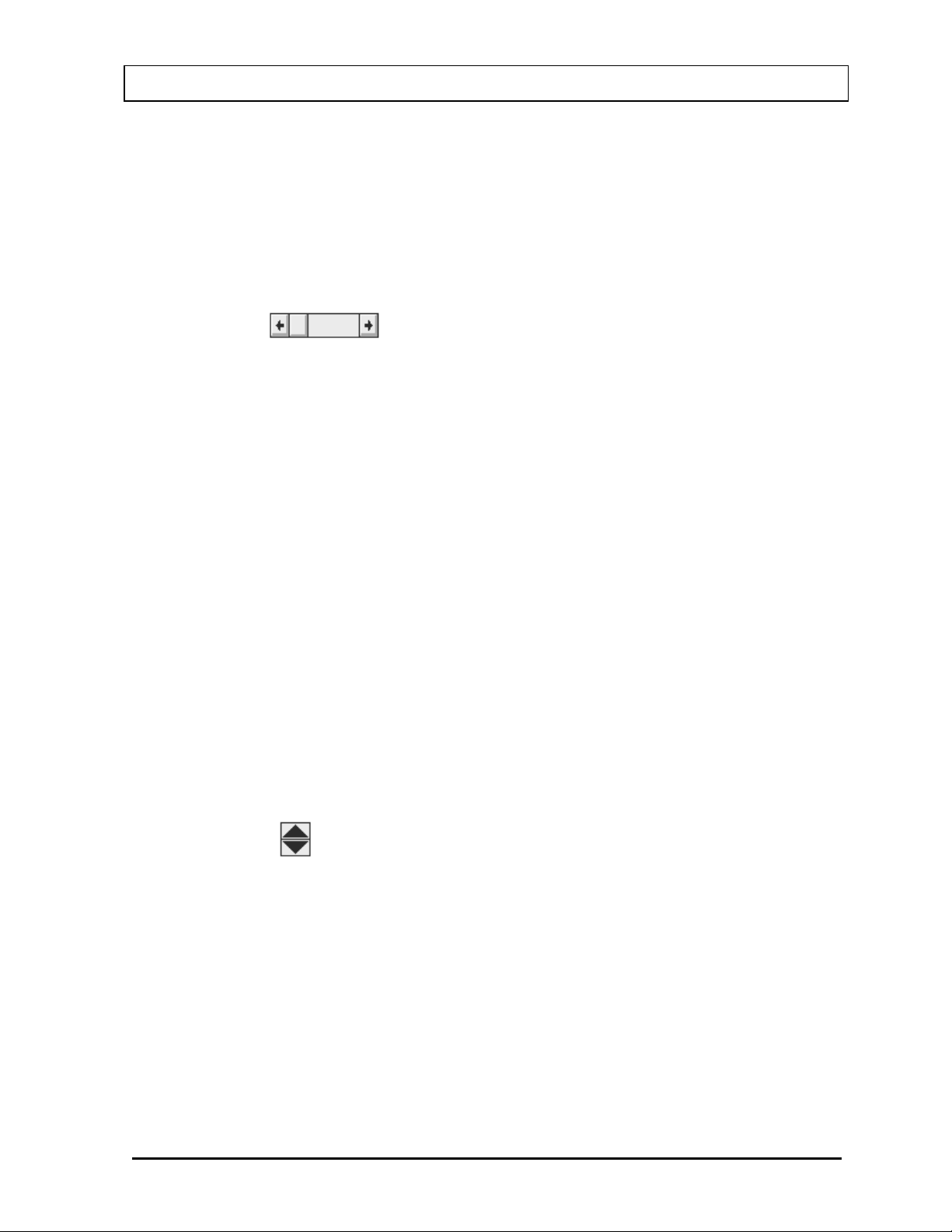
CAPINTEC, INC. CAPTUS® 3000
There is one special type of text box that is used in the CAPTUS
®
3000 for input of
comments that will appear on test reports. In these boxes up to 8,000 characters of
text may be entered. Within the box, text will automatically wrap from one line to the
next as it is typed in. The user may also move to the next line by using the Enter key.
Ctrl+Tab causes a tab to be entered into the text and the cursor to move to the next
tab position (remember pressing just Tab will move you to the next control).
Scroll Bars
There are two types of scroll bars, horizontal and vertical. They are used to change
the value of some parameter within the program.
When using the pointing device to manipulate a scroll bar there are a number of
actions that will cause the bar to change. Clicking the arrow at an end of the bar will
cause the “value” of the scroll bar to change in that direction by an amount referred to
as a small change. Clicking the bar itself at any location between the end arrow and
the slider will cause the value to change in that direction by an amount referred to as
a large change (usually 8 to 32 times the amount of a small change). The slider may
also be moved by placing the cursor on the slider, pressing the left pointer button
down and holding it there while you “drag” the slider to the desired position.
The scroll bar may also be adjusted from the keyboard. The scroll bar is activated
through the Tab key. When it is active the slider will blink. The slider can then be
positioned using the following keys:
Up Arrow ................... Moves the slider a small change up or to the right
Right Arrow ............... Moves the slider a small change to the right or up
Down Arrow ............... Moves the slider a small change down or to the left
Left Arrow .................. Moves the slider a small change to the left or down
Home ........................ Moves the slider all the way to the left or down
End ........................... Moves the slider all the way to the right or up
Spin Control
The spin control is also used to adjust values. The control consists of two back to
back arrows. Clicking an arrow with the cursor causes the value under control to
change in the specified direction. The spin button can only be controlled with the
pointing device.
List Controls
There are two types of “list” controls used in the CAPTUS
®
3000. Both appear quite
similar on the screen (refer to bottom of Figure 3-1). The only difference in
appearance is that on the Drop-Down Combo control, the arrow is not attached to text
box portion, while on the Drop-Down List control the arrow is attached. In function
both controls are similar except for one item. On the Drop-Down Combo control the
November 13 GENERAL OPERATING INSTRUCTIONS 3-5
Page 38

CAPINTEC, INC. CAPTUS® 3000
user can either enter new data directly into the text box or select from the list. In the
Drop-Down List control the user can only select from the list.
To select an entry from the list, use the pointing device left button to click the down
arrow. The list will appear. If there are more items on the list than can be shown
vertical scroll bars will appear on the right edge of the list. Place the pointer over the
desired entry and double-click the left pointing device button. The box will retract and
only the selected item will be displayed. Once the control is selected the up and down
arrows may also be used to scro l l through the lis t of items.
Menu Bars
Across the top of many forms you will find a menu bar. In the example the menu bar
in Figure 3-1
level menu items. A menu item can be selected either with the pointing device or by
typing Alt+K where K is the letter underlined in the name of the menu item. In some
cases the top-level menu item causes action to be taken immediately. In other cases
selecting it will cause another dialog box to appear. Selecting an item in the same
way is then necessary.
Icons
Icons are graphic symbols located at the top of user module test screens (refer to
Figure 3-3). The icons that are in color are active and therefore are selectable. The
icons that are grayed are inactive and therefore not selectable.
contains two items: File and Setup. These are referred to as the top-
An icon can be activated in one of two ways:
• positioning the pointing device over the icon and clicking the pointing device's
left button once, or
• using the Tab key on the keyboard to move the highlight from icon to icon until
the desired control is highlighted and then press the Enter key.
Activating an icon cause it to perform the specified function. This may involve
additional dialog boxes or various other modes of interaction with the user.
Keyboard Control
Most commands or actions can also be activated by keyboard strokes. The command
buttons and menu bar items are all controlled from the keyboard in the same manner.
Each word has one letter underlined. Holding down the Alt key, and then pressing the
underlined letter on the keyboard activates the selection. Almost every action in the
CAPTUS
®
3000 can be accomplished from keyboard control in this manner.
3-6 GENERAL OPERATING INSTRUCTIONS November 13
Page 39
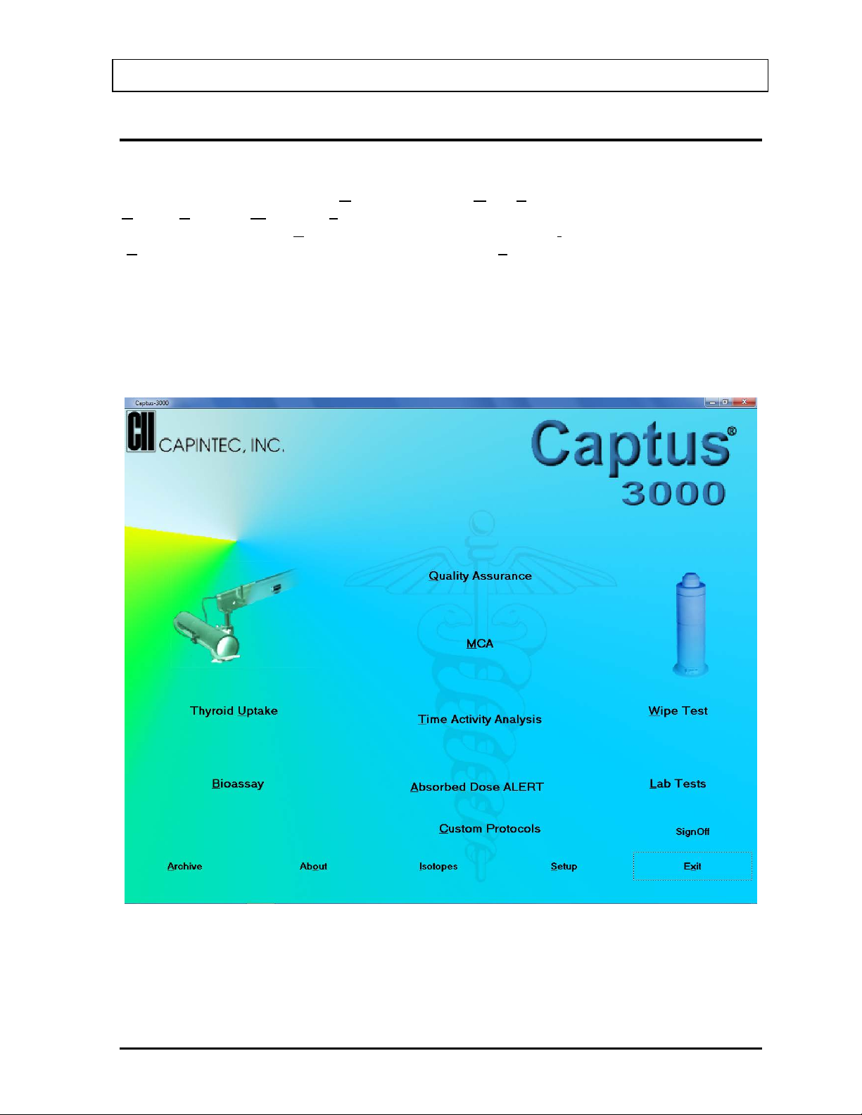
CAPINTEC, INC. CAPTUS® 3000
CAPTUS SCREENS
The CAPTUS® 3000 Main screen appears as shown in Figure 3-2. This screen provides
access to all the user modules (Quality Assurance, MCA, Tim e Activity An alysis, Thyroid
Uptake, Bioassay, Wipe Test, Lab Tests). At the bottom of the screen, access is provided to
General Setup modules (Setup), an Isotope Reference Library (Isotopes), Archived results
(Archive) and contact information for Capintec, Inc. (About). To select a module, move the
pointing device’s cursor over the name of the module you wish to select. A highlight box will
appear around the module title. Then, single left click activate the module.
Note: The Absorbed Dose ALERT and Custom Protocols selections shown below are
optional modules and must be purchased separately in addition to the CAPTUS
3000 system. The related button will be displayed on the Main screen after a valid
license is entered for each module in Setup.
®
Figure 3-2
November 13 GENERAL OPERATING INSTRUCTIONS 3-7
Page 40
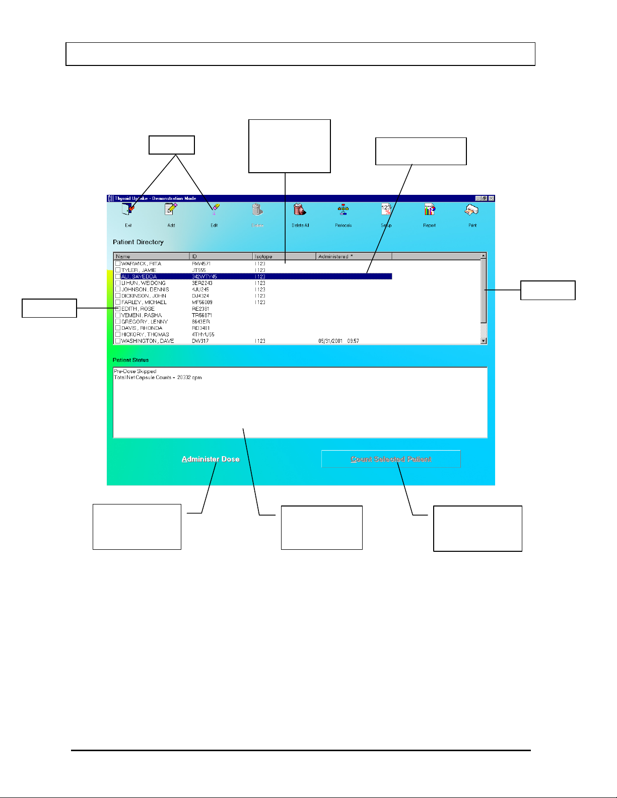
CAPINTEC, INC. CAPTUS® 3000
Icons
Patient
Scroll Bar
Selected Patient
Check Box
Box Showing
Command Button
Command Button
Typical Test Screen
Directory Box
(List of records in
the database)
(Highlighted)
(Currently
Accessible)
Highlighted
Patient’s Status
(Currently
Inaccessible)
Figure 3-3
3-8 GENERAL OPERATING INSTRUCTIONS November 13
Page 41

CAPINTEC, INC. CAPTUS® 3000
Text Entry
Frame around a
Buttons
Command Button:
Made and Exit
Command Button:
Made and Exit
Text Entry Box
Current Selection
Command Button:
Locations
Typical Input Screen
Box
group of Radio
For Comments
Discard Changes
Save Changes
Add More Wipe
Figure 3-4
November 13 GENERAL OPERATING INSTRUCTIONS 3-9
Page 42
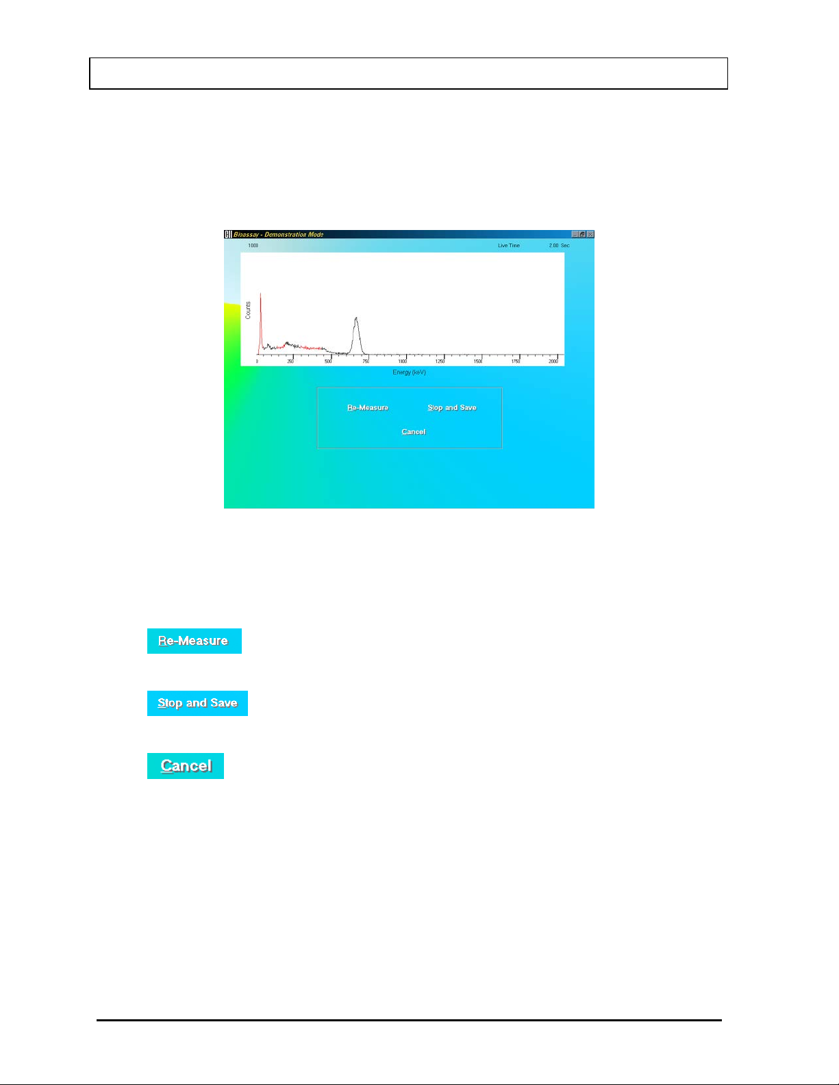
CAPINTEC, INC. CAPTUS® 3000
Measurement Screen
The Measurement screen is identical in all the test procedures and is as shown in Figure 3-5.
The live time elapsed while counting appears on the upper right hand corner of the screen.
The spectrum of the measurement is displayed in the white box.
Figure 3-5
The counting lasts for a duration as specified on the Test Setup screen.
To interrupt the counting, three options are available:
•
button or press Alt+R – To discard collected counts and begin counting
again.
•
button or press Alt+S – To stop collecting counts midway and save
the data.
•
button or press Alt+C – To stop collecting counts midway and discard the
data collected.
3-10 GENERAL OPERATING INSTRUCTIONS November 13
Page 43
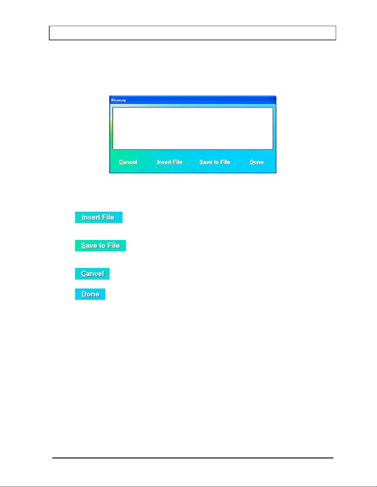
CAPINTEC, INC. CAPTUS® 3000
Add Comments Screen
The screen for adding comments to reports is identical to those for all the test procedures.
You may type in the comments as free text using standard editing keys.
Figure 3-6
The following options are available on this screen:
•
button or press Alt+I – To copy comments from an existing text file
(.txt files only).
•
button or press Alt+S – To save the entered comments as a text file
(.txt file only).
•
button or press Alt+C – To discard the changes made and quit.
•
button or press Alt+D – To save the changes made and quit.
November 13 GENERAL OPERATING INSTRUCTIONS 3-11
Page 44
CAPINTEC, INC. CAPTUS® 3000
First letter of the desired record
box is active
ALT + Underlined letter
Tab(s) and Enter
First letter of the desired
active
ALT + Underlined letter
Tab(s) and Enter
SHORTCUT KEYS
All Screens
Operation Key(s)
Cycle through all items on the screen Tab
Select from a list of records in the database
Scroll up or down the list of records in the database
Move up or down in the list of records in the database
Select a function or command
(Name field), when the records
Page Up and Page Down, when
the records box is active
and , when the records box is
active
OR
Exit to the previous screen Esc
Input Screens
Operation Key(s)
Cycle through fields on the screen Tab
Select from a drop-down list
Select within a group of mutually exclusive options and , when group is active
Choose a Command (e.g. Cancel, Done, New in Figure
3-4 above)
Cancel changes made and exit to the previous screen Esc
3-12 GENERAL OPERATING INSTRUCTIONS November 13
selection, when drop-down box is
OR
Page 45

CAPINTEC, INC. CAPTUS® 3000
CAUTION: Be sure the instrument has reached room temperature prior to opening
the box. (Leave the box in the room 24 hours before opening it.)
CHAPTER 4
GENERAL SETUP
INSTALLATION .............................................................................................. 4-1
ENVIRONMENT REQUIREMENTS ................................................................. 4-2
Operational ................................................................................................. 4-2
Storage ........................................................................................................ 4-2
POWER REQUIREMENTS .............................................................................. 4-3
TURN ON PROCEDURE ................................................................................. 4-3
LOG ON .......................................................................................................... 4-4
Sign In ......................................................................................................... 4-4
Sign Off ....................................................................................................... 4-5
Admin Log On............................................................................................. 4-5
User Log On ................................................................................................ 4-6
ADD USER ...................................................................................................... 4-7
Add User – Staff Member ........................................................................... 4-7
Add User – Not a Staff Member ................................................................. 4-8
CHANGE PASSWORD ................................................................................... 4-8
LOG ON REPORT ........................................................................................... 4-9
Displaying Selected User .......................................................................... 4-10
Delete User ................................................................................................ 4-10
Invalidate User ........................................................................................... 4-10
Revalidate User ......................................................................................... 4-11
Displaying Data by Date ............................................................................ 4-11
Printing Report .......................................................................................... 4-11
Exiting ........................................................................................................ 4-11
FIRST TI ME STARTUP .................................................................................. 4-12
System Parameters ................................................................................... 4-12
Quality Assurance Tests ........................................................................... 4-14
Measurement Setups ................................................................................ 4-15
NORMAL STARTUP ...................................................................................... 4-16
INSTALLATION
Initial installation and checkout procedures are described in this section. Your system has
been shipped from the factory pre-configured and fully tested.
If your system includes a Floor Stand, installation consists of placing the components on the
Stand and securing them in place. If your system includes a Table Top Stand, installation
consists of placing the components on a sturdy table or bench. Refer to the included
"UNPACKING AND ASSEMBLY INSTRUCTIONS" document for more details.
November 13 GENERAL SETUP 4-1
Page 46
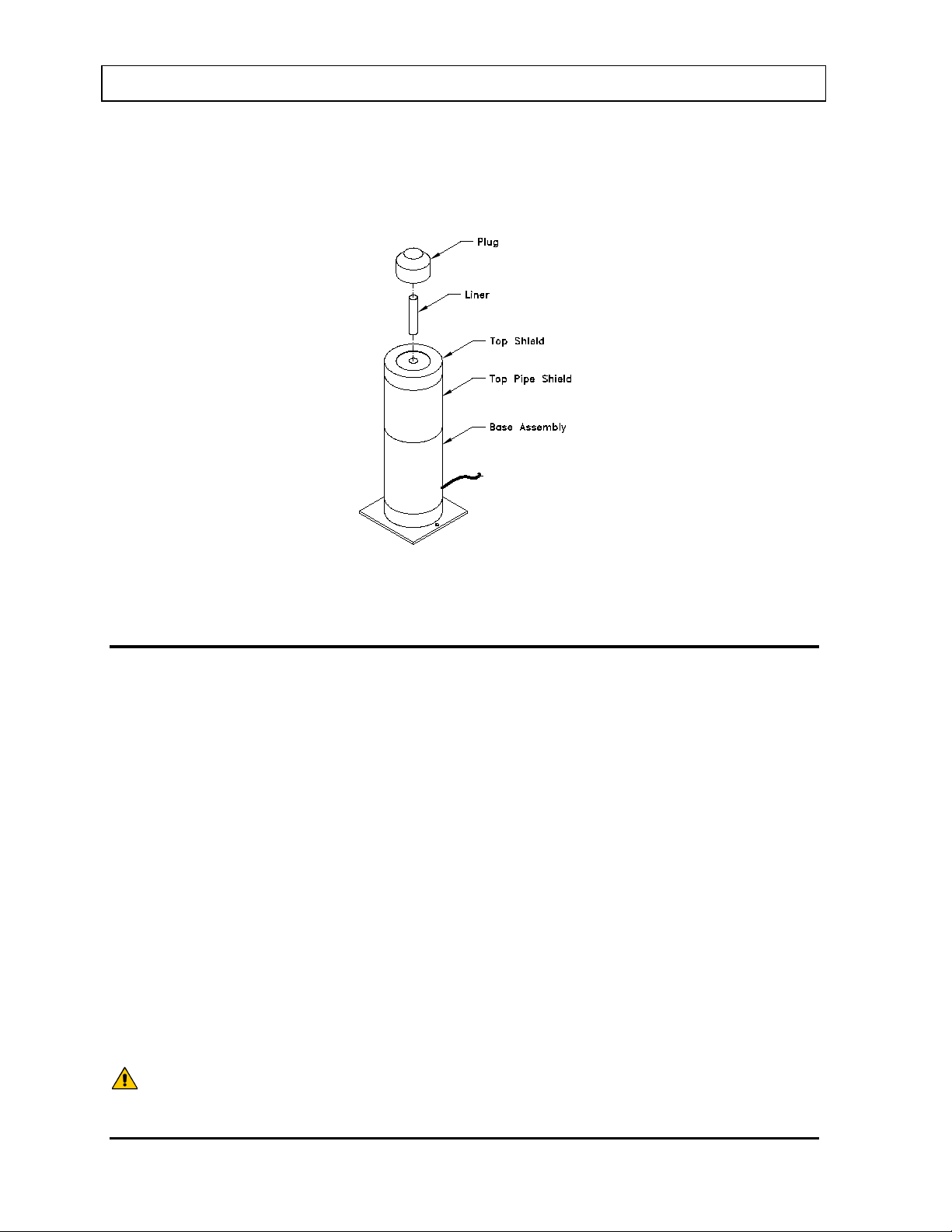
CAPINTEC, INC. CAPTUS® 3000
CAUTION: If these environmental requirements are not followed, the instrument may
display erroneous readings.
Note: If the system includes a Well, please verify that a Well Liner has been inserted into
the Well before use (refer to Figure 4-1 Well Counter Assembly). This prevents
contamination of the Well Detector if a spill or leak occurs.
Figure 4-1 Well Counter Assembly
ENVIRONMENT REQUIREMENTS
Operational
The instrument should be located where the level of the background radiation is as low and
as constant as possible.
The instrume nt should be located where the temperature is stable within a range of +50°F to
+85°F (+10°C to +30°C) and the maximum relative humidity is 90% non-condensing to
warrant maximum reliability and accuracy.
The instrument should be located where the barometric pressure is within a range of 27–31
inches of mercury (91–105 kilopascals).
Storage
The instrument should be stored where the temperature is stable and the range is from
+39°F to +110°F (+4°C to +43°C) and the maximum relative humidity is 90% non-condensing
to warrant maximum reliability.
The instrument should be stored where the barometric pressure is within a range of 15–33
inches of mercury (51–112 kilopascals).
4-2 GENERAL SETUP November 13
Page 47

CAPINTEC, INC. CAPTUS® 3000
CAUTION: If the input voltage is not within the stated limits, the unit may not
POWER REQUIREMENTS
function correctly or may be damaged.
Input Power
Line Voltage: ............. 115 or 230 Vac depending on model ordered
Line Frequency: ........ 60 or 50 Hz
Current: ..................... 2.0 Ampere @ 115V
1.1 Ampere @ 230V
Fuse: For 115V use T 3.15AH, 250V, (Time Delay)
For 230V use T 2.5AH, 250V, (Time Delay)
Isolation Transformer Output
Computer and Monitor combined
Output Voltage: ......... 115Vac
Current Output: ......... 1.9A
Frequency: ................ 50/60Hz
Printer
Output Voltage: ......... 115Vac
Current Output: ......... 0.7A
Frequency: ................ 50/60Hz
TURN ON PROCEDURE
Verify all system components are mounted securely and all cables are connected. Connect
the Isolation Transformer main power cable to a medical grade wall socket.
All software necessary for proper operation of your CAPTUS
®
3000 Thyroid Uptake System
has been pre-installed and tested at the factory to ensure trouble-free setup.
Note: To remove main power from the system, the Isolation Transformer main power cable
must be unplugged from the wall socket.
There are three power switches associated with the system:
• the monitor has a power switch,
• the computer has a power switch, and
• the printer has a power switch.
Turn on all three switches.
Your system will power up, go through the computer boot-up sequence, and display the
Windows
®
start up screen.
November 13 GENERAL SETUP 4-3
Page 48
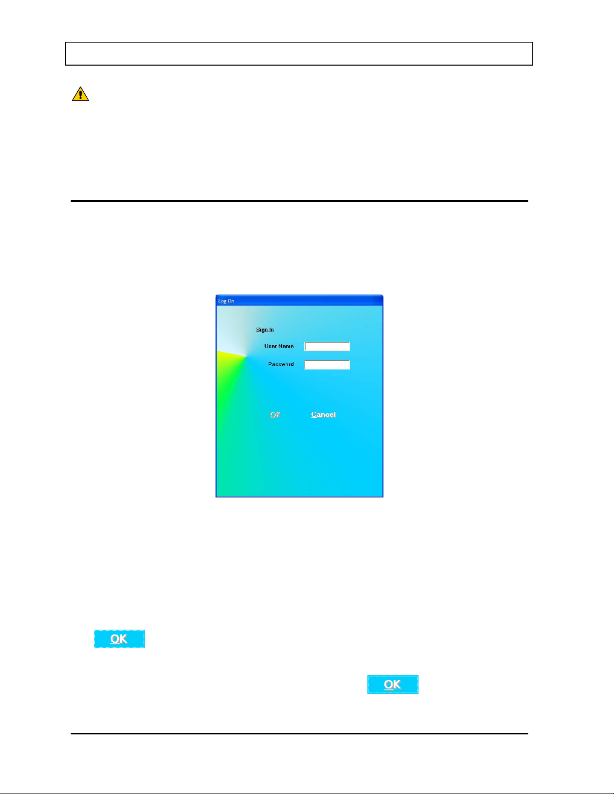
CAPINTEC, INC. CAPTUS® 3000
CAUTION: Changing the date or time while a timed test is in progress (for example,
clock for daylight saving changes checkbox is not checked.
a 24 hour Thyroid Uptake Test) might affect the results or introduce
unexpected error. Care should be taken to evaluate any potential impact
for ongoing tests before changing the date or time. Verify that the under
the Date and Time Properties in Windows that the Automatically adjust
LOG ON
Note: Before performing any measurements, allow the system to warm up at least 30
minutes.
To run the CAPT U S
®
3000 software, double-click on the CAPTUS® 3000 icon. When the
program is launched, Figure 4-2 Log On Sign In Window will appear:
Figure 4-2 Log On Sign In Window
Sign In
Users must set up by the Administrator prior to l ogging on to the CA PTUS
Names and Passwords are case sensitive.
Input the User Name and then the Password. Asterisks (*) will appear when the Password is
entered.
The
button will be enabled when entries have been made in both User Name and
Password.
When the User Name and Password are correct, clicking on
screen and Figure 4-12 Main Screen will appear.
4-4 GENERAL SETUP November 13
®
3000. User
will exit the Sign On
Page 49
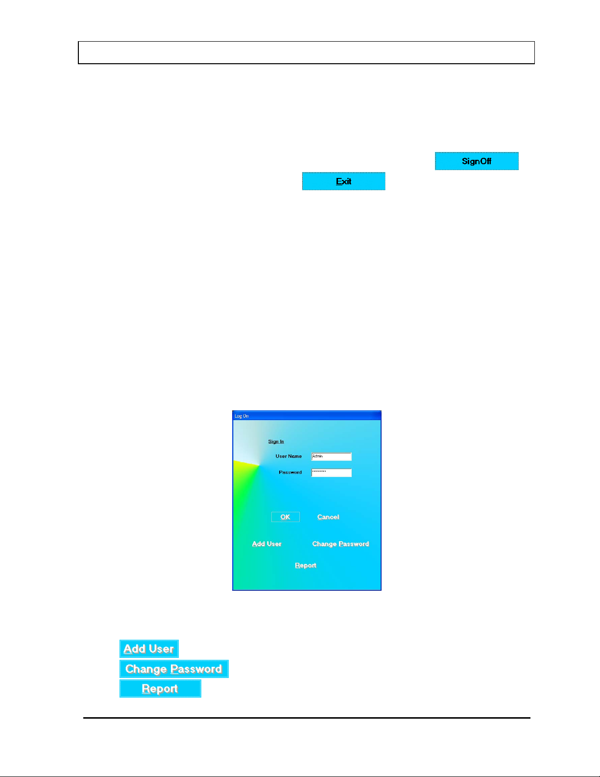
CAPINTEC, INC. CAPTUS® 3000
Note: If the Startup Tips option is enabled, Figure 4-9 Startup Tips Window will appear
instead of Figure 4-12 Main Screen.
Sign Off
After signing in to the CAPTUS
button located on the Main Screen above the
®
3000, a user may sign off by clicking the
button (Refer to Figure 4-12
Main Screen). Clicking this button will end t he session for the currently logged on user and
return to Figure 4-2 Log On Sign In Window so that another user can sign on.
Admin Log On
The Administrator is the user who has control of user management. The Administrator can
view and print Log On / Log Off Reports and can add, delete or invalidate users.
For the Administrator to log on:
• In the User Name text box, input Admin and press the Tab key.
• In the Password text box, input the password (AlphaDrive is default) and press the
Tab key.
Note: User Names and Passwords are case sensitive.
Note: It is recommended that the Admin password be changed at first log in.
Figure 4-3 Admin Log On Sign In Window
When Admin logs on, the following buttons will appear:
•
•
•
November 13 GENERAL SETUP 4-5
– this allows the Admin to add users,
– this allows the Admin to change the Admin password and,
– allows viewing and printing of the User Log On Report.
Page 50
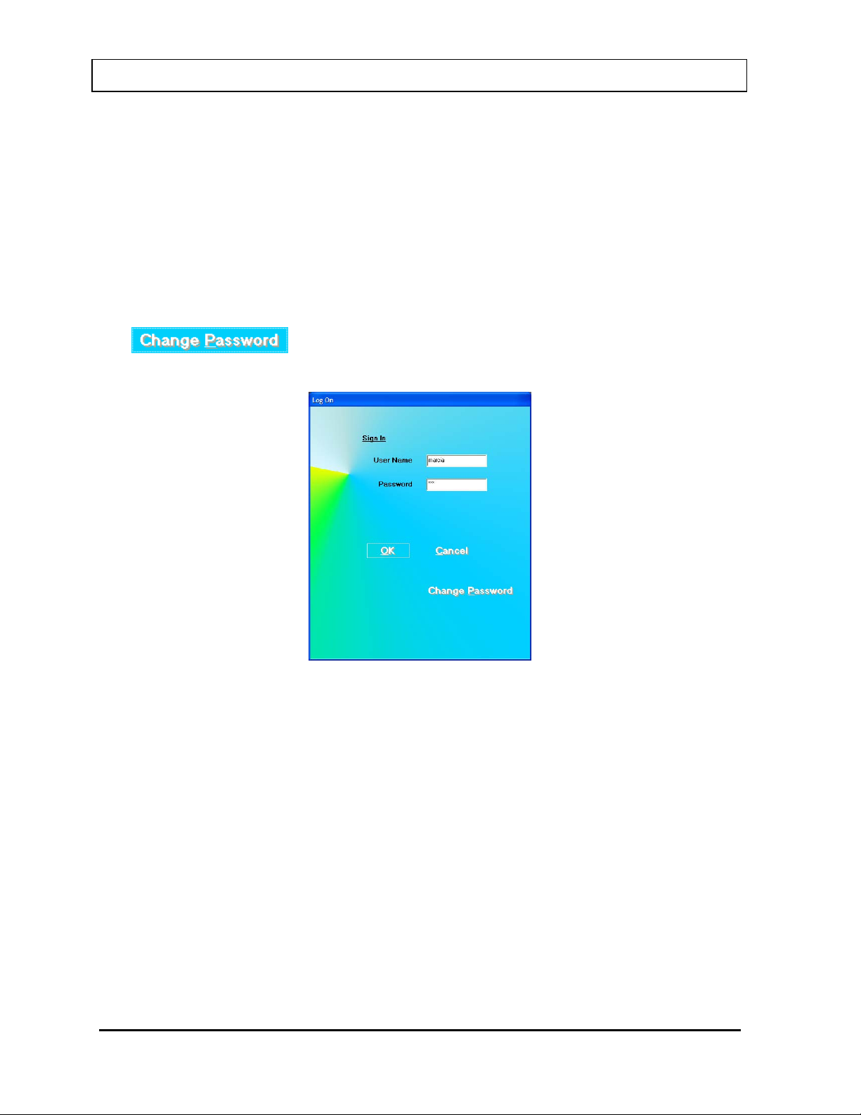
CAPINTEC, INC. CAPTUS® 3000
User Log On
Once the Admin sets up a user, the user may log on to the CAPTUS
For a user to log on:
• In the User Name text box, input the user’s name and press the Tab key.
• In the Password text box, input the user’s password and press the Tab key.
Note: User Names and Passwords are case sensitive.
®
3000 program.
The
his/her own password.
button will appear. Clicking this button allows a user to change
Figure 4-4 User Log On Sign In Window
4-6 GENERAL SETUP November 13
Page 51
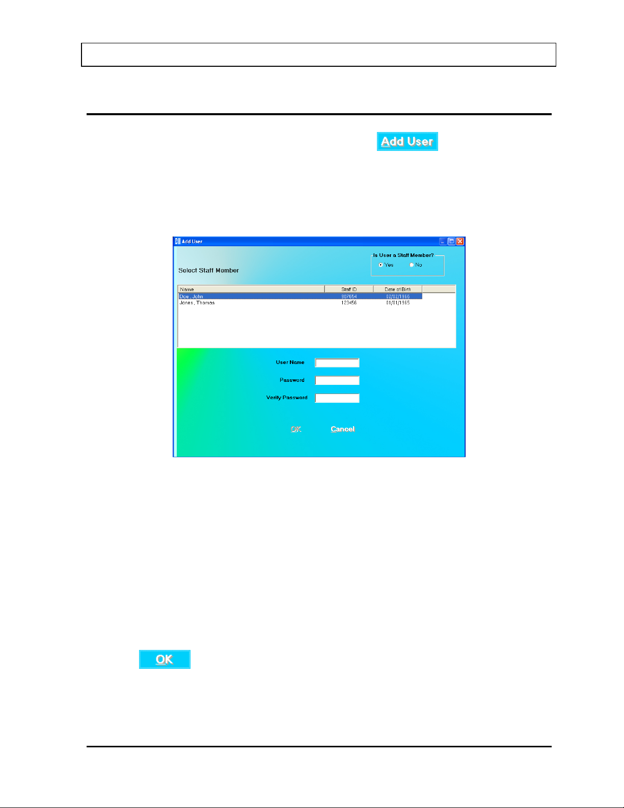
CAPINTEC, INC. CAPTUS® 3000
ADD USER
From Figure 4-3 Admin Log On Sign In Window, click the button.
Add User – Staff Member
If the user to be added is a staff member, in the “Is User a Staff Member?” frame, select the
Yes radio button. Figure 4-5 Add User (Staff Member) Window will appear.
Figure 4-5 Add User (Staff Member) Window
Note: In order for the Staff Member List to be displayed, Staff Member’s must be added in
the Bioassay module in the CAPTUS
®
3000 software as described in CHAPTER 11:
BIOASSAY, SECTION: ADDING STAFF MEMBERS. If no Staff Members have been
added, the “Is User a Staff Member?” frame will be grayed-out (disabled) and
defaulted to No and the Select Staff Member List will not be displayed.
Select the Staff Member from the displayed list of Staff Members. Setting the user as a Staff
Member allows that user to access, count and print his/her own Bioassay data.
Input the new User Name for the selected Staff Member and then the Password. Input the
Password again in the Verify Password text box.
When the
button is clicked, the new user and password will be accepted and
Figure 4-3 Admin Log On will re-appear.
November 13 GENERAL SETUP 4-7
Page 52
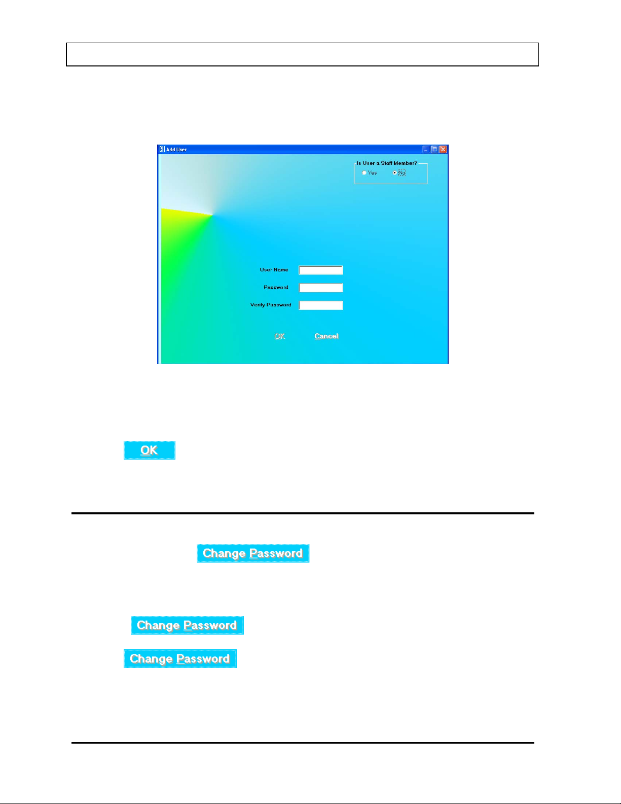
CAPINTEC, INC. CAPTUS® 3000
Add User – Not a Staff Member
If the user to be added is not a staff member, in the “Is User a Staff Member?” frame, select
the No radio button. Figure 4-6 Add User (Not a Staff Member) Window will appear.
Figure 4-6 Add User (Not a Staff Member) Window
Input the new User Name and then the Password. Input the Password again in the Verify
Password text box.
When the
button is clicked, the new user and password will be accepted and
Figure 4-3 Admin Log On will re-appear.
CHANGE PASSWORD
From Figure 4-3 Admin Log On Sign In Window, the Admin may change his/her own
password by clicking the
button.
Note: It is recommended that the Admin password be changed at first log in.
From Figure 4-4 User Log On Sign In Window, a user may change his/her own password by
clicking the
button.
When the
button is clicked, Figure 4-7 Change Password Window
will appear.
4-8 GENERAL SETUP November 13
Page 53
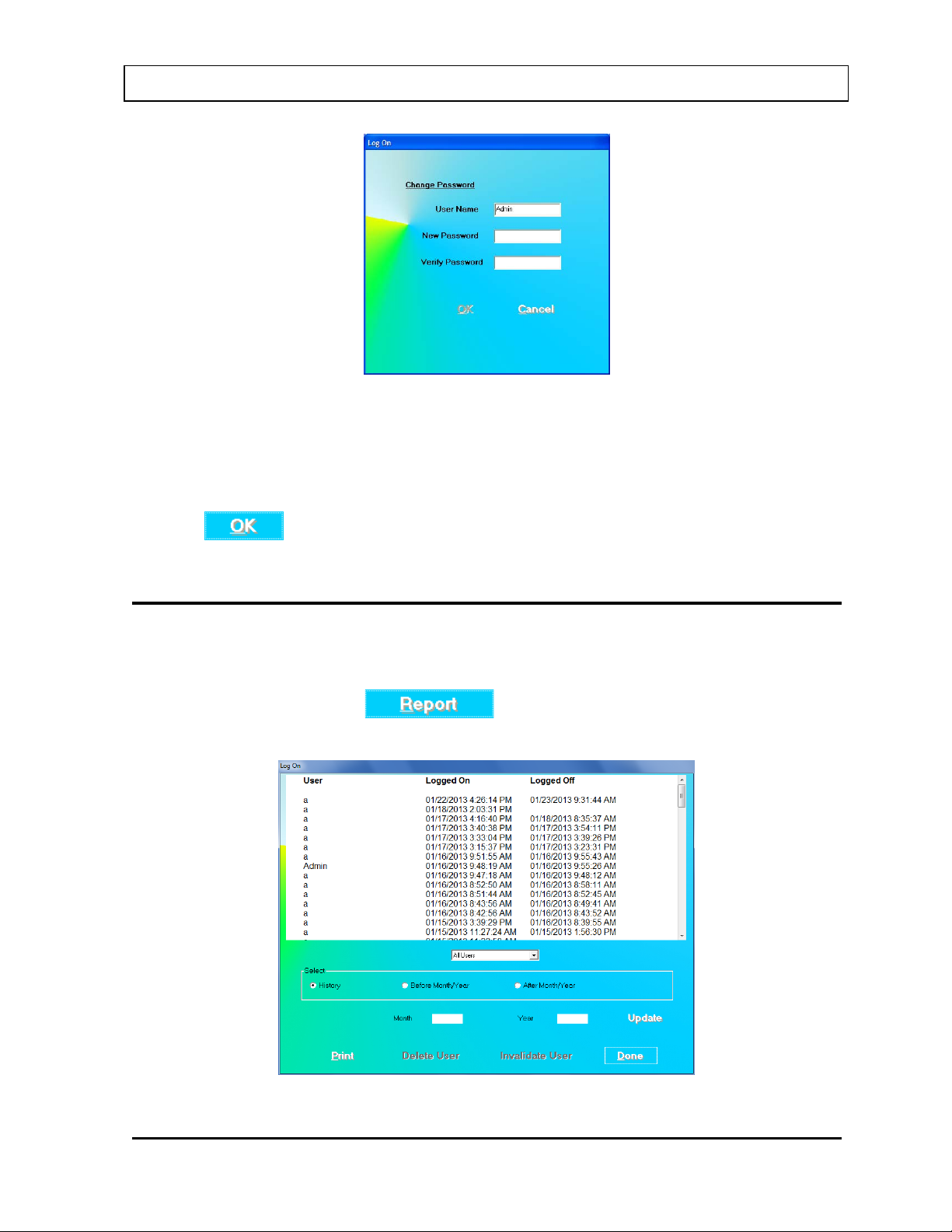
CAPINTEC, INC. CAPTUS® 3000
Figure 4-7 Change Password Window
The current User Name is displayed and cannot be changed.
Input the New Password and then re-input it again for verification.
Click the
button to accept the new password.
LOG ON REPORT
A log is kept of when each user logs on and logs off.
When Admin is logged on (Figure 4-3 Admin Log On Sign In Window), the Log On Report
may be viewed by clicking the
button. Figure 4-8 Log On Report Window
will appear.
Figure 4-8 Log On Report Window
November 13 GENERAL SETUP 4-9
Page 54
CAPINTEC, INC. CAPTUS® 3000
The User, Log On Date/Time and Log Off Date/Time are displayed in reverse chronological
order.
When All Use rs are displayed, the
and buttons are
disabled (grayed-out).
Displaying Selected User
The Drop-Down List box contains the names of all the users.
To select a user, click the Drop-Down List box and click the desired User Name. Click the
button. The Log On Report window will be updated to show only the log on data
for that user. The
and buttons will now be enabled.
Note: The
and buttons are not enabled if Admin is the
selected user, since Admin may not be deleted or invalidated.
Delete User
To delete a user and all log on data for the user, select the User Name from the Drop-Down
List box and click the
button. Click the button. A verification
message window will appear asking if you want to delete the user and the user log. Click
to delete the user and log. Click to abort the delete.
Invalidate User
Invalidating a user will remove the user from the list of users who may log onto the program
but it will not delete the user’s log on data.
To invalidate a user, select the User Name from the Drop-Down List box and List box and
click the
button. Click the button. A verification message
window will appear asking if you want to invalidate the user.
Click
to abort the invalidation.
Click
to invalidate the user. A message window will appear indicating that the
selected user can no longer log on.
The Log On Report window will be updated to show that the selected user in invalid.
4-10 GENERAL SETUP November 13
Page 55
CAPINTEC, INC. CAPTUS® 3000
Revalidate User
An invalidated user can be revalidated. To revalidate a user, select the User Name from the
Drop-Down List box and List box and click the
button. Click the
button. A verification message window will appear asking if you want to revalidate the user.
Click
to abort the revalidation.
Click
enter a new password for the user. Click
Click
to revalidate the user. A message window will appear asking if you want to
to use the user’s previous password.
to enter a new password for the user. Figure 4-7 Change Password
Window will appear allowing a new password to be entered.
The Log On Report window will be updated to show that the selected user is no longer
invalid.
Displaying Data by Date
Log On Data may be displayed before or after a given month and year.
To display the Log On Data by date:
• In the Month text box, input the month in numeric format (1 to 12).
• In the Year text box, input the year in 4-digit year format (2000 to 2050).
• Click the Before Month/Year or After Month/Year radio button.
• Click the
button.
The selected data will be displayed.
Printing Report
The displayed Log On Data may be printed.
To print a report of the displayed Log On Data, click the
button.
Exiting
To exit the Log On Reports window and return to Log On window, click the
button.
November 13 GENERAL SETUP 4-11
Page 56
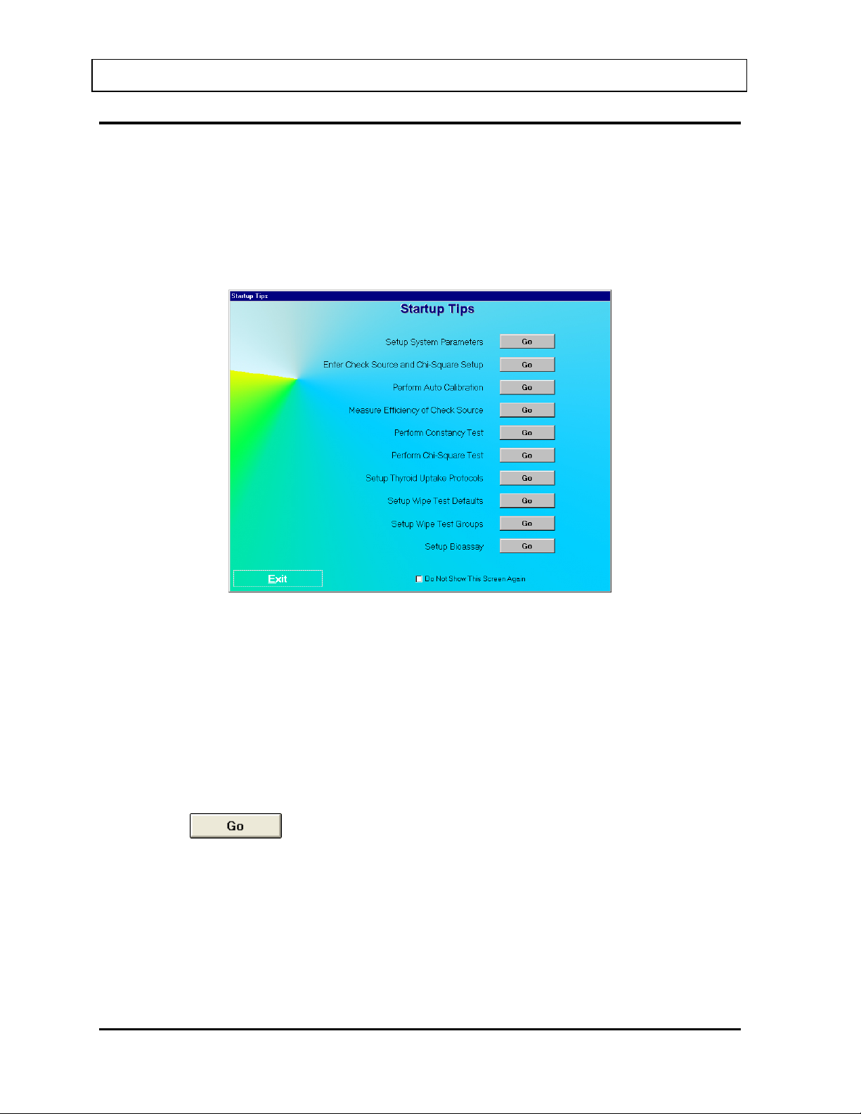
CAPINTEC, INC. CAPTUS® 3000
FIRST TI ME STARTUP
If this is the first time the CAPTUS® 3000 software is run, the Startup Tips screen will be
displayed as shown in Figure 4-9 Startup Tips Window.
The Startup Tips screen provides a quick and convenient way to get ready for performing
test procedures. This screen provides access to the System Parameters, Quality Assurance
Tests and the preliminary Measurement Setups that need to be performed before beginning
measurements.
Figure 4-9 Startup Tips Window
The system parameters for the CAPTUS
®
3000 software can be altered through the Setup
module. The Setup module (Figure 4-10 Setup Module Screen) standardizes units of
measurement, printing mode, date format and detector type for the entire system. A report
header can be entered that will appear at the top of all report printouts. An option is also
provided to enable or disable the viewing of the Startup Tips that will appear when the
CAPTUS
®
3000 software is started.
System Parameters
1. Click the
button beside “Setup System Parameters”. Figure 4-10 Setup
Module Screen will appear.
4-12 GENERAL SETUP November 13
Page 57
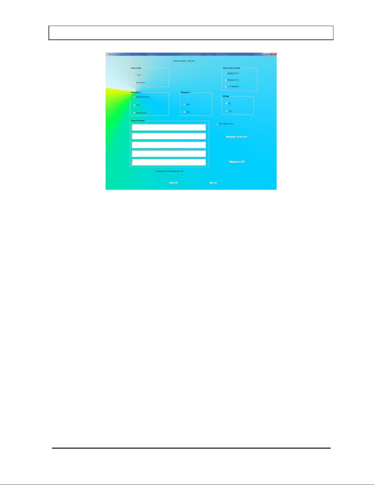
CAPINTEC, INC. CAPTUS® 3000
Figure 4-10 Setup Module Screen
Except for the report header, all other parameters are predefined with default settings.
The Serial Number at the top of the screen is specific to your system and is set at the
factory.
2. To change the default settings for unit of activity, mode of printing or format of the date,
click in the appropriate radio button. You can safely change any of these at any time
during the use of your system.
Note: If the date format is changed, the conversion will apply to stored data also. If the
unit for counts is changed, the new unit will apply to the new measurements only.
3. To select another detector type, click on one of the radio buttons in the Detector 1 box.
The Detector 2 box options, Well and None, are applicable, only when you select a Flat
Faced Probe as Detector 1.
Note: Your detector setting has been selected for the specific hardware shipped with
your system. Therefore, detector default should not be changed without
consulting with the technical service staff at Capintec.
4. If Cap-DICOM Software is installed on you system, select the Yes radio button in the
DICOM Frame. Otherwise, select the No radio button.
5. To enter a heading for each printed report, click in the first blank box under Report
Header. Enter the first line of the header. The length of each line is limited to 40
characters per line. To enter another line, click in the blank box below or press the Tab
key. An example of report header is as given below in Figure 4-11 Report Header
Frame. This header will appear centered at the top of each report printout.
November 13 GENERAL SETUP 4-13
Page 58
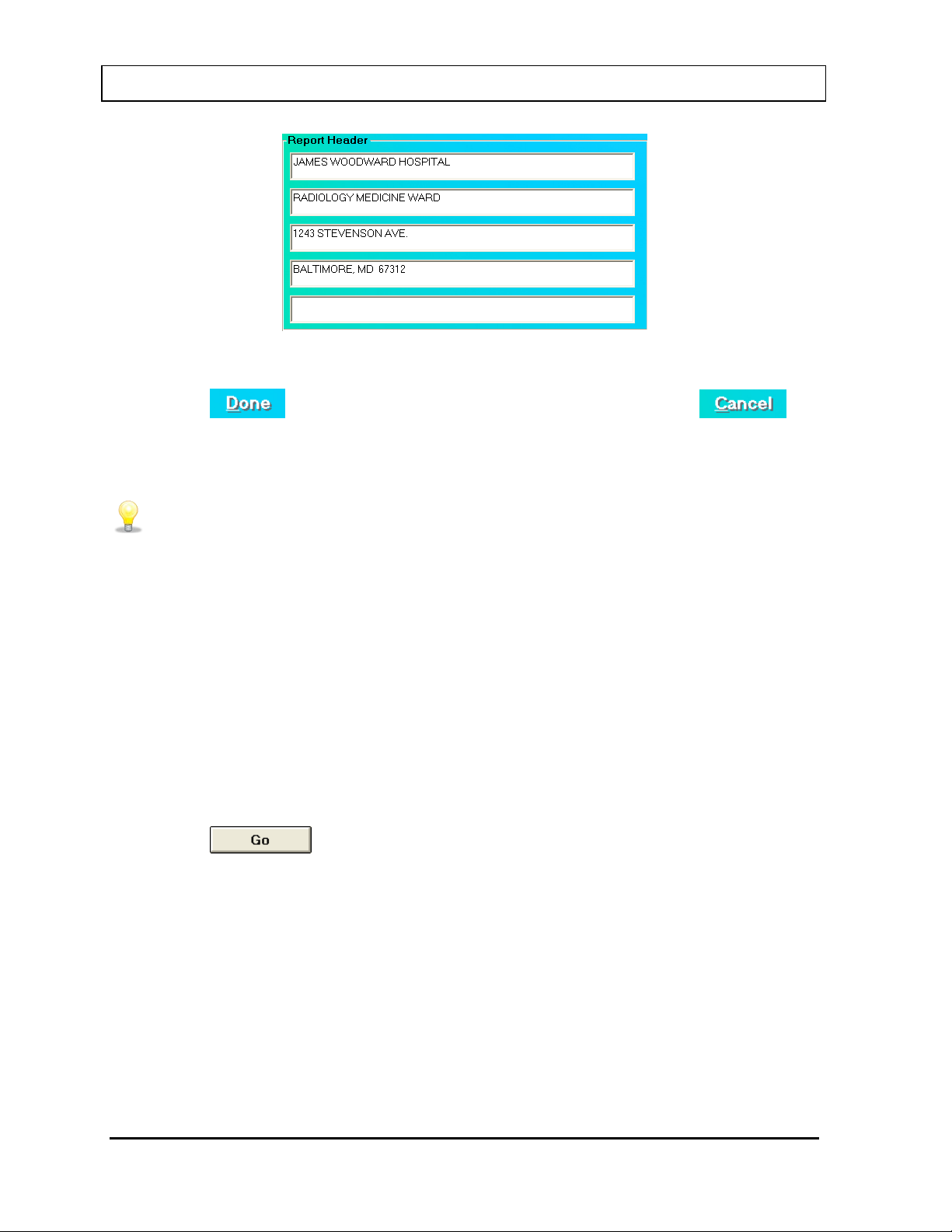
CAPINTEC, INC. CAPTUS® 3000
QUICK TIPS:
facility as the report header.
Figure 4-11 Report Header Frame
6. Click the
button or press Alt+D to save the changes or click the
button or press Alt+C to exit without saving the changes. Figure 4-9 Startup Tips
Window will re-appear.
• To move between boxes use the Tab key and to move within boxes use or
keys.
• To customize your report printouts, you can input the address of your medical
Quality Assurance Tests
Note: All QA Tests (Enter Check Source and Chi-Square Setup, Auto Calibration, Measure
Efficiency, Constancy Test, and Chi-Square Test) must be performed before any
measurements can take place. Measurement Setups (Thyroid Uptake Protocols,
Wipe Test Defaults, Wipe Test Groups, Bioassay) need only be performed if required.
Before performing any of the Quality Assurance tests, allow the system to warm up at least
30 minutes.
1. Click the
button beside “Enter Check Source and Chi-Square Setup”.
2. Enter the required fields. For details on the screen, see the pages listed in Reference
Pages below.
3. Upon exiting the Check Source and Chi-Square Setup screen, you will be automatically
returned to the Startup Tips screen.
4. Continue with the next test in the list (e.g., Auto Calibration).
5. Repeat steps 1-4 for each remaining test (Measure Efficiency, Constancy Test, and ChiSquare Test).
4-14 GENERAL SETUP November 13
Page 59
CAPINTEC, INC. CAPTUS® 3000
6. If you do not wish to perform the Measurement Setups at this time, click the
button or press Alt+E to close the Startup Tips Screen. Otherwise, continue to the
Measurements Setups section.
Note: If you do not want the Startup Tips window to appear the next time the CAPTUS
3000 software is started, click in the check box “Do Not Show This Screen Again”
at the bottom of the window after all setups have been completed.
Reference Pages
For further information on the tests, refer to the following pages in the manual:
• Setup QA Parameters ....................................... 5-2
• Perform Auto Calibration ................................... 5-5
• Measure Efficiency of Check Source ................. 6-5
• Perform Constancy Test .................................... 5-10
• Perform Chi-Square Test ................................... 5-15
Measurement Setups
®
Note: It is only necessary to setup the tests that you are going to perform.
1. Click the
button beside “Setup Thyroid Uptake Protocols”.
2. Enter the required fields. For details on the screen, see the pages listed in Reference
Pages below.
3. Upon exiting the Setup Thyroid Uptake Protocols screen, you will be automatically
returned to the Startup Tips window.
4. Continue with the next setup in the list (e.g., Wipe Test Defaults).
5. Repeat steps 1-4 for each remaining setup (Wipe Test Groups, and Bioassay).
6. Click the
Note: If you do not want the Startup Tips window to appear the next time CAPTUS
button or press Alt+E to close the Startup Tips window.
®
3000 software is started, click in the check box “Do Not Show This Screen Again”
at the bottom of the window after all setups have been completed.
It is recommended that this selection remain unchecked, otherwise it will be
displayed every time the program is started.
Reference Pages
For further information on the tests, refer to the following pages in the manual:
November 13 GENERAL SETUP 4-15
Page 60
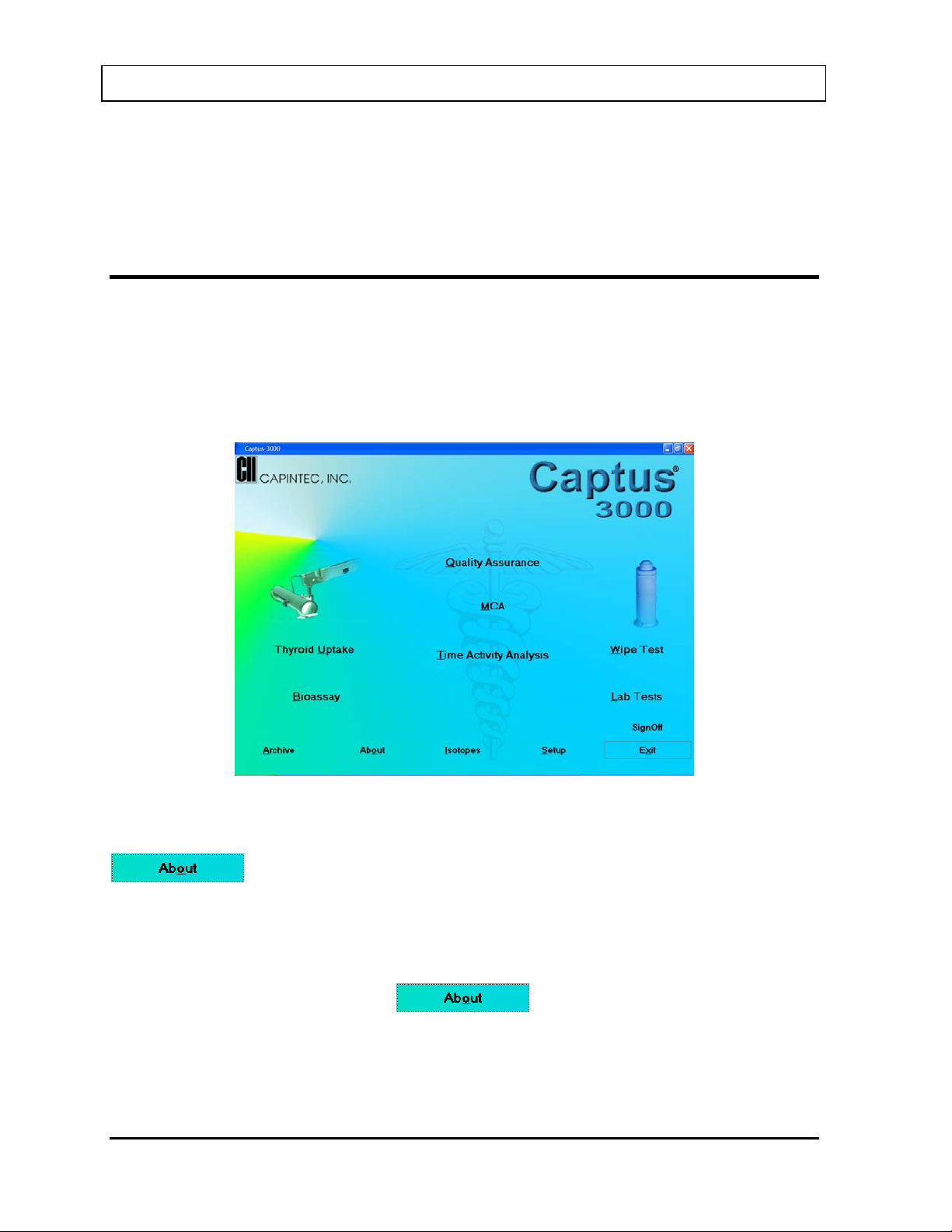
CAPINTEC, INC. CAPTUS® 3000
• Setup Thyroid Uptake Protocols ......................... 7-3
• Setup Wipe Test Defaults .................................. 8-3
• Setup Wipe Test Groups .................................... 8-6
• Setup Bioassay .................................................. 11-2
NORMAL STARTUP
To run the CAPT U S® 3000 software, double-click on the CAPTUS® 3000 icon. If the Startup
Tips window was disabled, the Main screen will appear as shown in Figure 4-12 Main
Screen. Before beginning any measurements, allow the system to warm up at least 30
minutes. It is recommended that the system be left on with the CAPTUS
running because the MCA board is powered whenever the CAPTUS
running.
®
3000 program
®
3000 software is
Figure 4-12 Main Screen
The software version installed on your CAPTUS
®
3000 can be identified by selecting the
button located at the bottom of the Main screen. The user cannot alter
information concerning the software version. Any software upgrades will automatically
change the version number accordingly.
Note: The Serial Number, together with your software version, is to be used as a reference
when contacting the CAPINTEC Service Center for information or assistance. To get
the software version, click the
button on the CAPTUS® 3000 Main
screen.
4-16 GENERAL SETUP November 13
Page 61

CAPINTEC, INC. CAPTUS
CHAPTER 5
QUALITY ASSURANCE
INTRODUCTION ............................................................................................. 5-1
Recommended Routine for CAPTUS
SETTING UP QA PARAMETERS ................................................................... 5-2
AUTO CALIBRATION ..................................................................................... 5-5
About Auto Calibration ............................................................................. 5-10
CONSTANCY TEST ....................................................................................... 5-10
CHI-SQUARE TEST ....................................................................................... 5-15
MDA TEST ..................................................................................................... 5-19
VIEWING SYSTEM PARAMETERS ............................................................... 5-22
VIEWING AND PRINTING HISTORY ............................................................. 5-24
®
3000 System ................................ 5-1
®
3000
INTRODUCTION
There are several Quality Assurance tests that should be performed periodically on the
CAPTUS
The Quality Assurance (QA) tests include the following: Auto Calibration, Constancy Test,
Chi-Square Test and MDA (Minimum Detectable Activity) Test. The CAPTUS
performs all these tests quickly and automatically using the two 0.5µCi reference sources,
Cs137 and Eu152, supplied with the system. The software automatically saves all the results
from these tests.
For systems with two detectors, (Uptake Probe and Well Counter), the Quality Assurance
tests must be performed on both the detectors. Note that if a Drilled Probe is used, both the
Probe and Well should be calibrated, even though there is only one detector. Each software
module uses the calibration parameters of the particular detector that is associated with the
module. For example, the Thyroid Uptake program uses the calibration parameters of the
Probe, and the Wipe Test program uses those of the Well.
Note: For systems with a Well Counter or a Drilled Probe, sources should be in the range of
Recommended Routine for CAPTUS
1. Turning on the System – If your system will be used in a single location, we recommend
®
3000 system to ensure its optimum operation.
®
3000
0.1 to 1.0µCi.
®
3000 System
that you leave the computer powered at all times. The monitor and printer may be turned
off at the end of the day.
July 14 QUALITY ASSURANCE 5-1
Page 62

®
CAPINTEC, INC. CAPTUS
3000
Note: If you prefer to turn off the entire system every day, then allow at least 30 minutes
for system warm up before performing any calibration procedures or making any
measurements.
2. Schedule for performing the Quality Assurance (QA) Tests
a. Setting Up QA Parameters -- Once, at initial system setup (page 5-2)
b. Auto Calibration ---------------- Daily, before the first procedure (page 5-5)
c. Constanc y Test ----------------- Daily, before the first procedure (page 5-10)
d. Chi-Square Test ---------------- Quarterly (page 5-15)
e. MDA Test ------------------------ Quarterly (page 5-19)
While performing any Quality Assurance test, ensure the following:
• Consistent placement of the radioactive standard source in the detector is critical.
The source should not be leaning against the sides.
• Keep background rates constant throughout the counting process by ensuring that no
radioactive sources or other dosed patients are in the immediate area.
Note: Perform all the needed QA procedures for one detector and then, repeat the
same for the second detector, if applicable.
3. Record Keeping – After the system is setup and all the QA Tests have been completed
successfully, it is recommended that a list be printed of the system parameters for your
records (Refer to the VIEWING AND PRINTING HISTORY section on page 5-22). These
are all the default values used while doing various measurements (Thyroid Uptake,
Bioassay, Wipe Test etc.). In case of suspicious results in any module, confirm the Setup
values in that module with the values in your records. All QA results are stored
automatically and may be accessed at any time (Refer to the VIEWING AND PRINTING
HISTORY section on page 5-24).
SETTING UP QA PARAMETERS
To access the QA tests, click the button or press Alt+Q on the CAPTUS®
3000 Main screen. Figure 5-1 Quality Assurance Main Screen appears as shown.
5-2 QUALITY ASSURANCE July 14
Page 63
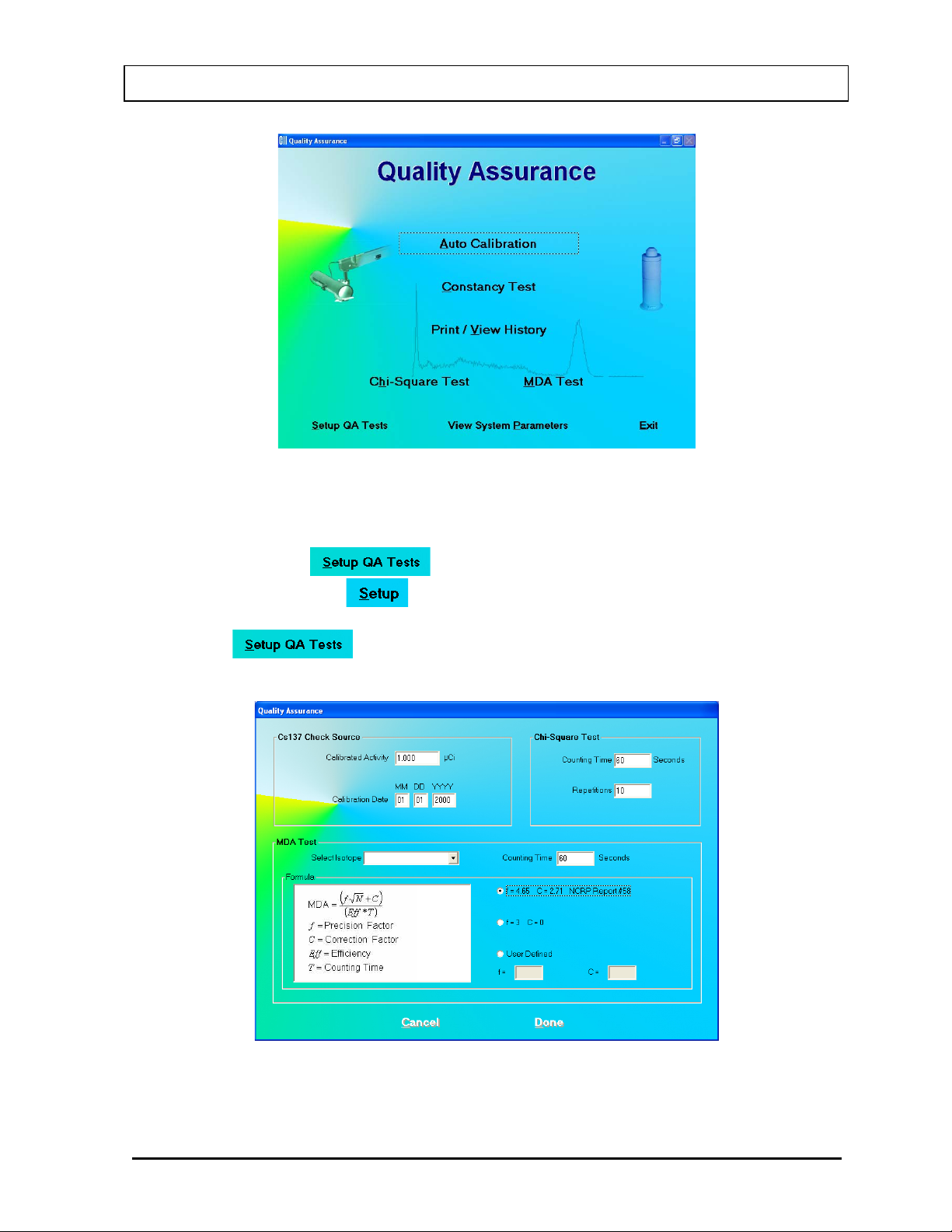
®
CAPINTEC, INC. CAPTUS
3000
Figure 5-1 Quality Assurance Main Screen
The following tests require setting up parameters prior to performing the test: Constancy
Test, Chi-Square Test and MDA Test. This can be done via the QA Setup screen, which is
accessible through the button at the bottom of Figure 5-1 Quality Assurance
Main Screen or through the button provided on all QA Test screens.
1. Click the button or press Alt+S on Figure 5-1 Quality Assurance Main
Screen. Figure 5-2 Quality Setup Screen appears as shown.
Figure 5-2 Quality Setup Screen
July 14 QUALITY ASSURANCE 5-3
Page 64
®
QUICK TIPS:
and click the button.
CAPINTEC, INC. CAPTUS
3000
2. Constancy Test Parameters – These are provided in the Cs137 Check Source frame.
Enter the Calibrated Activity and Calibration Date in the appropriate text boxes marked
on the Cs137 standard source.
3. Chi-Square Test – Counting Time is the duration over which counts are collected each
time and Repetitions is the number of times the counts are collected. They are set by
default to a value of 60 seconds and 10 repetitions, respectively. To change these
values, click in the appropriate text box in the Chi-Square Test frame and type in the
new values. Restrict Repetition value to 5, 10, 15 or 20.
4. MDA Test Parameters
a. Click in the Select Isotope drop-down box. View the drop-down list and click on the
desired isotope. This defines the ROIs over which the activity will be measured.
Without an isotope selection, the MDA Test cannot be performed.
b. To change the default Counting Time, click in the Counting Time box in the MDA
Test frame and type in the new value.
c. T o alter the values being used in the formula (as shown on the left side) for MDA
calculation, click the desired radio button in Formula frame.
Note: The default settings for Precision Factor (f) and Correction Factor (C) are 4.65
and 2.71 respectively (Knoll method). Selecting the User Defined radio button
enables the text boxes for entering your own values of ‘f’ and ‘C’.
5. Click the button or press Alt+D to save the changes or click the
button to cancel the changes made and return to Figure 5-1 Quality Assurance Main
Screen.
• To return to th e CAPTUS® 3000 Main screen from the QA Tests screen, click
the button or press the Esc Key.
• Rest your mouse close to each module title on Figure 5-1 Quality Assurance
Main Screen to read a brief description of that function.
• Setup values can be conveniently changed later if needed from any QA Test
screen.
• Keep a record of the parameters set above. To do so, click the
button on Figure 5-1 Quality Assurance Main Screen
5-4 QUALITY ASSURANCE July 14
Page 65
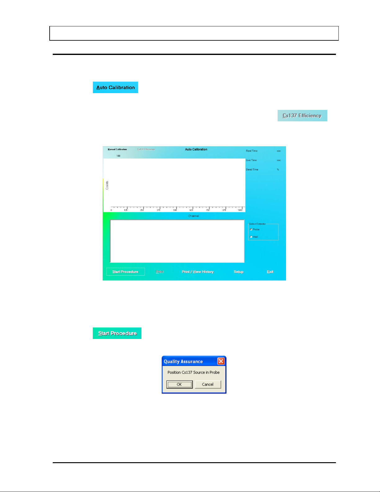
®
CAPINTEC, INC. CAPTUS
AUTO CALIBRATION
Calibration is done with Cs137 and Eu152 standard sources.
1. Click the button or press Alt+A on Figure 5-1 Quality Assurance Main
Screen. Figure 5-3 Auto Calibration Screen will appear. When the procedure is started,
the spectrum appears in the upper half of the screen as it is being collected and displays
the measurement time elapsed in the upper right corner. Note that the
button at the top of the screen is enabled only after calibration has been done at least
once on that day.
3000
Figure 5-3 Auto Calibration Screen
2. Note that in the Select Detector frame, PROBE is selected by default. To change the
detector to Well, click the radio button marked WELL.
3. Click the button or press Alt+S to start the calibration procedure. The
screen appears as shown in Figure 5-4.
Figure 5-4
July 14 QUALITY ASSURANCE 5-5
Page 66
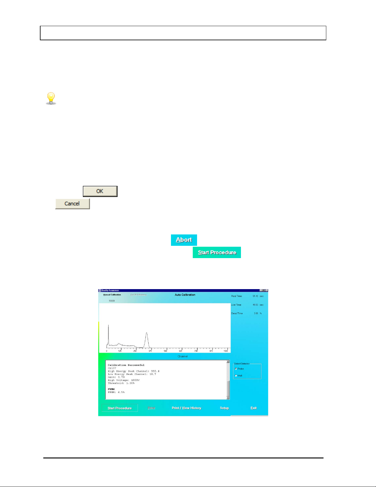
®
QUICK TIPS:
This positioning will provide reliable measurements.
CAPINTEC, INC. CAPTUS
3000
4. Place the Cs137 rod source in the selected detector. To ensure reproducible source
placement for the uptake probe, turn the uptake probe so that the collimator opening is
facing upwards towards the ceiling. Gently place the active end of the rod source onto the
middle surface of the crystal. The rod should stand freely and not lean to the side.
• To ensure that the Cs137 source rod is consistently placed in the center of the
probe face, the Rod Source Holder may be purchased from Capintec
(reference CHAPTER 15: CL EANING AND MAINTENANCE, SECTION:
ACCESSORIES AND REPLACEMENT PARTS), or
• you CAN fashion a piece of cardboard, Styrofoam or paper cup into a circle
with a hole in its center to put the rod through. The cardboard or cup will brace
against the inside cylindrical wall of the collimator to keep the rod in position.
Note: Never put a sharp instrument like a pen into the Well or Probe.
5. Click the button to proceed with the calibration process. Otherwise, click the
button to stop the process. As counting is progressing, the live spectra is
shown. The software will count for as long as necessary until sufficient counts are
acquired for proper calibration.
6. To stop the counting midway, click the button or press Alt+A. The collected data
is discarded. To re-start the process, click the button or press Alt+S.
7. After calibration is completed, the results box will display “Calibration Successful” as
shown in Figure 5-5 below.
Figure 5-5
5-6 QUALITY ASSURANCE July 14
Page 67
®
CAPINTEC, INC. CAPTUS
3000
8. Next, the screen appears as shown in Figure 5-6, prompting you to perform Linearity
Correction using Eu152. This step, though optional, is highly recommended for finetuning your system.
Figure 5-6
9. Click the button or press the Y key to proceed with further calibration.
Otherwise click the button or press the N key to stop here.
10. If you are continuing with Eu152, the screen appears as shown in Figure 5-7. Place the
Eu152 source in the selected detector in the same position as Cs137 and click the
button.
Figure 5-7
After the count collection is over, the system is fully calibrated. Complete results are
displayed in the lower half of the screen and all the data is automatically stored in the
system.
Note: If the calibration is not successful, click the button or press
Alt+M on the Auto Calibration screen. The MCA module is started. Refer to
CHAPTER 13: MCA. If this does not correct the problem, contact Capintec’s only
Authorized Service Center for service.
11. If the calibration was successful, Eu152 Linearity Correction results appear on the screen
and the software prompts you to perform Constancy Test as shown in Figure 5-8. Click
the button or press the Y key to proceed. Otherwise, click the
button or press the N key to exit the Auto Calibration procedure.
Note: If Cs137 efficiency has never been measured in your system, do not perform
Constancy Test at this time, because the test needs the Detector Efficiency value.
Click the button or press the N key and perform the Constancy Test
as described in the CONSTANCY TEST section in this chapter.
July 14 QUALITY ASSURANCE 5-7
Page 68
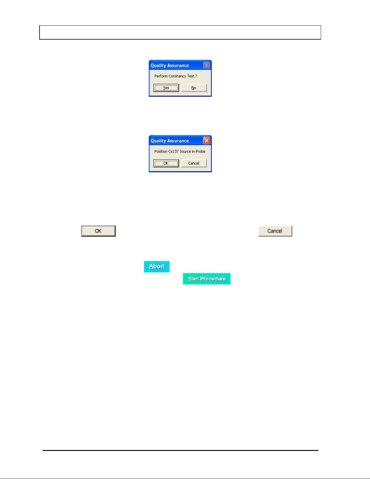
CAPINTEC, INC. CAPTUS
Figure 5-8
If you are performing the Constancy Test, Figure 5-9 will be displayed.
Figure 5-9
12. Place the Cs137 source rod in the selected detector. Since the Constancy Test is a
measure of reproducibility, it is important that the source be placed in exactly the same
position each time the Constancy Test is performed.
®
3000
13. Click the button to proceed with the test, or else click the button
to stop the process. As the counting progresses, the live spectra and measurement times
are displayed.
14. To stop the counting, click the button or press Alt+A. The collected data is
discarded. To re-start the process, click the button or press Alt+S.
15. After the test is completed, the results of the test appear in the box below as shown in
Figure 5-10. Note the Deviation value at the bottom.
5-8 QUALITY ASSURANCE July 14
Page 69
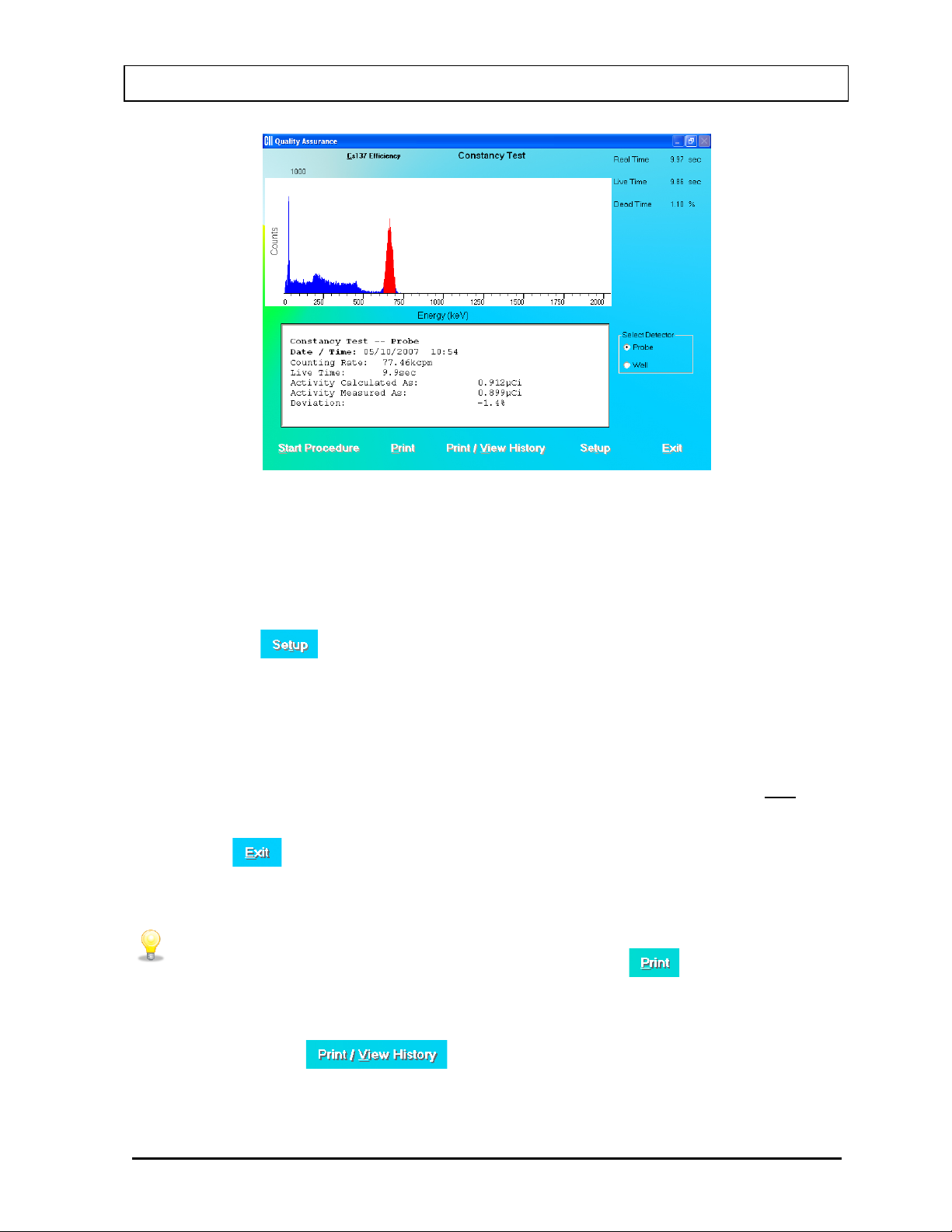
CAPINTEC, INC. CAPTUS
QUICK TIPS:
PRINTING HISTORY section on page 5-24).
Figure 5-10
An unacceptable deviation is indicated in red as HIGH.
If Deviation is indicated as HIGH, check the following:
• The positioning of the rod source, especially for the Probe detector.
• Ensure that there are no other sources (including dosed patients) in the area.
®
3000
• Click the button or press Alt+T at the bottom of the Constancy Test screen.
Calibrated Activity and Calibration Date should match your Cs137 standard.
If a problem is found with any of the three items above, then correct the problem and
repeat the Constancy Test.
If no problems are found with the above items, then the efficiency of the Cs137 standard
should be re-measured. If this does not correct the problem, contact Capintec’s only
Authorized Service Center for service.
16. Click the button or press Alt+E to exit and return to Figure 5-1 Quality Assurance
Main Screen.
• To print current results for record keeping, click the button or press
Alt+P on Auto Calibration or Constancy Test screen after calibration is
completed.
• To view or print results for all the Quality Assurance tests performed to date,
click the button or press Alt+V (Refer to the
VIEWING AND
July 14 QUALITY ASSURANCE 5-9
Page 70

®
CAUTION: Calibration is recommended before making any measurements. Refer to
the AUTO CALIBRATION section on page 5-5.
• Perform SETTING UP QA PARAMETERS on page 5-2 before perfor ming the
• Perform Auto Calibration before Constancy Test.
CAPINTEC, INC. CAPTUS
3000
About Auto Calibration
Calibration is done using Cs137 and Eu152 isotopes. First, calibration is performed with
Cs137 where the procedure makes use of its 662 keV and the 32 keV peaks to automatically
adjust the high voltage, gain, and zero offset (as required by MCA card) to provide a
calibration of approximately 2.0 keV per channel in the MCA. Next, Eu152 provides multiple
gammas over an energy range of 41 keV to 1,408 keV. The CAPTUS
®
3000 software
provides a point-by-point energy calibration using these gammas. This function corrects for
any non-linearity in response of the NaI detector and provides accurate identification of the
energy of the peaks. It is important to complete the calibration of your system using Eu152.
The ROI’s in the Thyroid Uptake and Lab Tests are based on the energy ranges defined by
the Eu152 calibration. In addition, the automatic peak identification program, which is
accessed in the Wipe Test and MCA, requires the Eu152 energy calibration in order to work
properly.
Unless an error message is displayed, the software will have succeeded in finding a set of
adjustments, which places the 662 keV gamma peak to within ±2 channels of the theoretical
value for a calibration of 2.00 keV per channel. The software has preset limits that prohibit
operation outside of appropriate voltage, gain, and zero adjust values.
The Auto Calibration Test also calculates detector resolution by determining the FWHM (full
width-half maximum) area of the peak, and dividing by the peak centroid location. For peaks
such as the 662 keV peak of Cs137 whose shape is symmetrical or appears to follow a
Gaussian distribution, the FWHM is generally close to 2.35 σ. For flat-faced detectors the
resolution should be <9.5 percent measured at the Cs137 662 keV peak. For well detectors
the resolution should be <10.0 percent. Detectors do age with use, and this will result in a
very slight increase (1% to 3%) in resolution over a period of several years. A rapid increase
in percent resolution may indicate a problem with the detector assembly.
Note: Monitoring the stability of the resolution over time is one of the best indications of the
overall system performance.
CONSTANCY TEST
This test compares the Cs137 standard source activity entered in the setup with the activity
that it measures. The activity entered in the setup is decay corrected by the software. The
counts measured in the Constancy test are converted to activity using efficiency values from
the Isotope Library. The deviation between the calculated and measured activity is the
percent error and should be within ±10%. If the deviation is outside ±10%, it will be indicated
as HIGH. NaI detectors are very sensitive and any radioactive sources even in neighboring
rooms may affect the results.
Constancy Test the first time.
5-10 QUALITY ASSURANCE July 14
Page 71
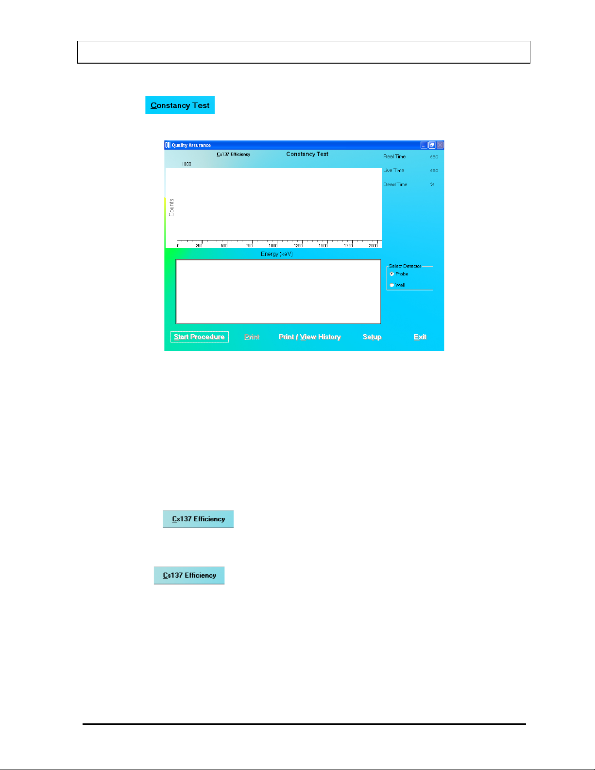
®
CAPINTEC, INC. CAPTUS
1. Click the button or press Alt+C on Figure 5-1 Quality Assurance Main
Screen. Figure 5-11 Constancy Test Main Screen will appear.
3000
Figure 5-11 Constancy Test Main Screen
2. If Cs137 efficiency has never been measured on your system, proceed to Step 3.
Otherwise, skip to Step 4.
3. Measuring Cs137 Efficiency – The Constancy Test requires Cs137 efficiency value as
measured on your system. This step enters the Cs137 efficiency value in the Isotope
Library, which is used for calculations every time Constancy Test is performed.
Note: This is a one-time procedure and should not to be repeated unless Constancy
Test is unsuccessful.
a. Click the button at the top of the screen or press Alt+C. The screen
appears as shown in Figure 5-12. Calibrated Activity and Date are already entered
from QA Setup done above.
Note: is enabled only after auto calibration has been performed that
day.
July 14 QUALITY ASSURANCE 5-11
Page 72
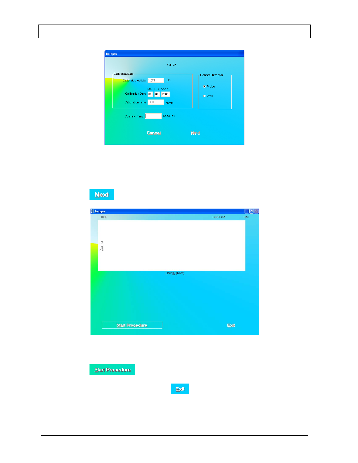
CAPINTEC, INC. CAPTUS
Figure 5-12
b. Input the Counting Time in seconds.
c. Note t he detector selection. To change the selection, click the appropriate radio
button in Select Detector frame.
d. Click the button. Figure 5-13 will appear.
®
3000
Figure 5-13
e. Click the button or press Alt+S to start measurements. Follow the on-
screen instructions.
f. After efficiency is measured, click the button to return the Constancy Test
screen.
5-12 QUALITY ASSURANCE July 14
Page 73
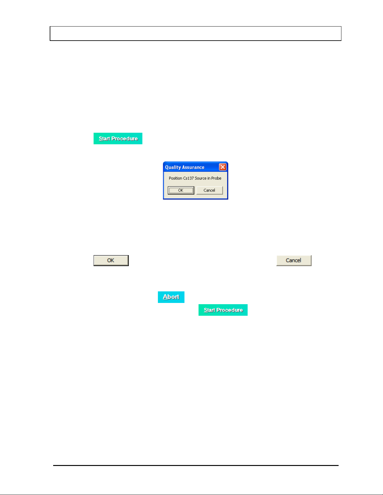
®
CAPINTEC, INC. CAPTUS
3000
g. For systems with two detectors, if the efficiency has never been measured on the
other detector, then repeat Step 3. Remember to change the detector selection in
Step 3c.
Note: For further information, refer to CHAPTER 6: ISOTOPES, SECTION:
MEASURING EFFICIENCY.
4. Note the detector selected in the Select Detector frame. To change the detector, click
the appropriate radio button.
5. Click the button or press Alt+S to start the test. The screen appears as
shown in Figure 5-14.
Figure 5-14
6. Place the Cs137 source rod in the selected detector. Since the Constancy Test is a
measure of reproducibility, it is important that the source be placed in exactly the same
position each time the Constancy Test is performed.
7. Click the button to proceed with the test, or else click the button
to stop the process. As the count progresses, the live spectra and measurement times
are displayed.
8. To stop the counting, click the button or press Alt+A. The collected data is
discarded. To re-start the process, click the button or press Alt+S.
9. After the test is completed, the results of the test appear in the box below as shown in
Figure 5-15 Constancy Test Results Screen. Note the Deviation value at the bottom.
July 14 QUALITY ASSURANCE 5-13
Page 74
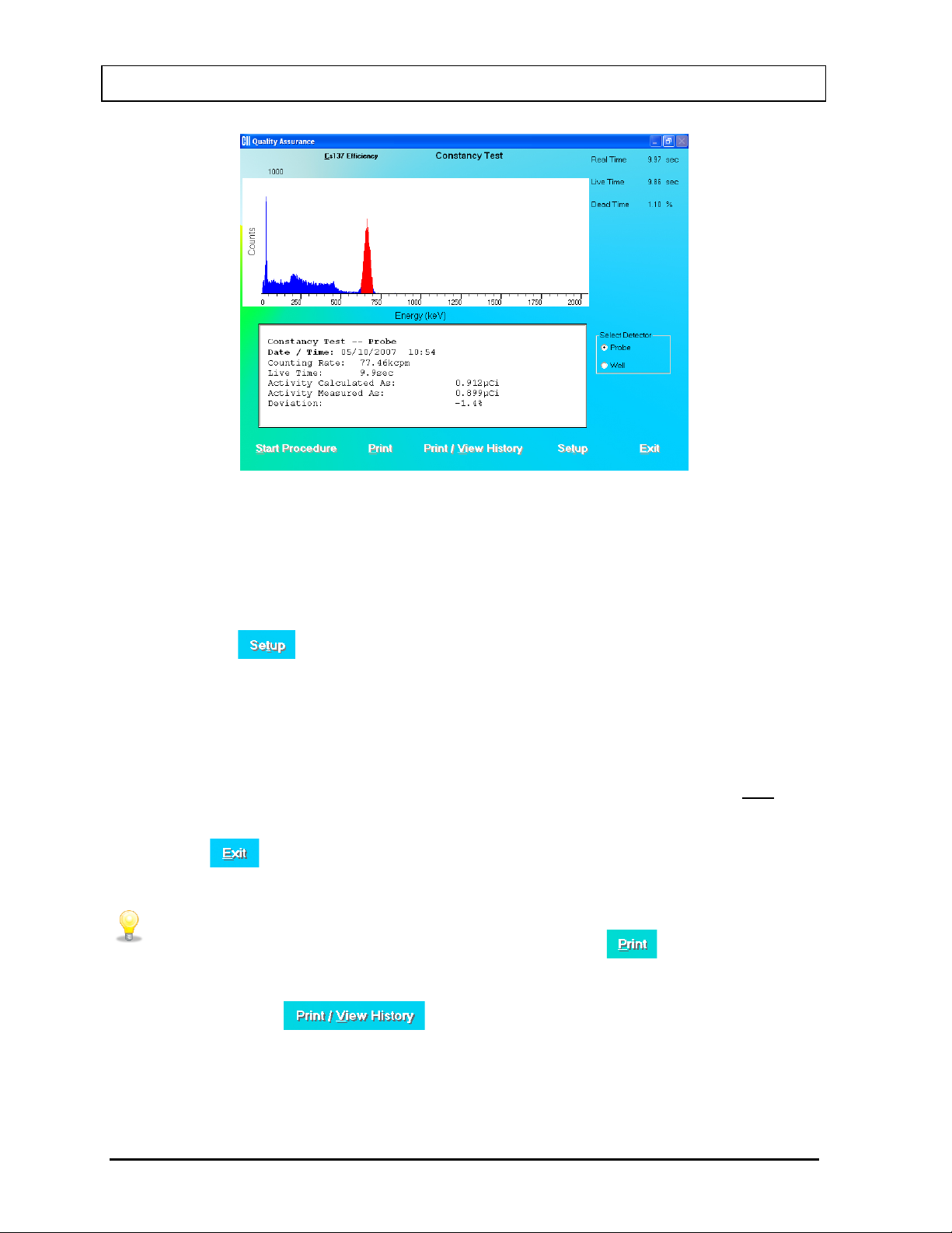
CAPINTEC, INC. CAPTUS
QUICK TIPS:
PRINTING HISTORY section on page 5-24).
Figure 5-15 Constancy Test Results Screen
An unacceptable deviation is indicated in red as HIGH.
If Deviation is indicated as HIGH, check the following:
• The positioning of the rod source, especially for the Probe detector.
• Ensure that there are no other sources (including dosed patients) in the area.
®
3000
• Click the button or press Alt+T at the bottom of the Constancy Test screen.
Calibrated Activity and Calibration Date should match your Cs137 standard.
If a problem is found with any of the three items above, then correct the problem and
repeat the Constancy Test.
If no problems are found with the above items, then the efficiency of the Cs137 standard
should be re-measured. If this does not correct the problem, contact Capintec’s only
Authorized Service Center for service.
10. Click the button or press Alt+E to exit and return to Figure 5-1 Quality Assurance
Main Screen.
• To print current results for record keeping, click the button or press
Alt+P on Constancy Test screen after the test is completed.
• To view or print results for all the Quality Assurance tests performed to date,
click the button or press Alt+V (Refer to the
VIEWING AND
5-14 QUALITY ASSURANCE July 14
Page 75
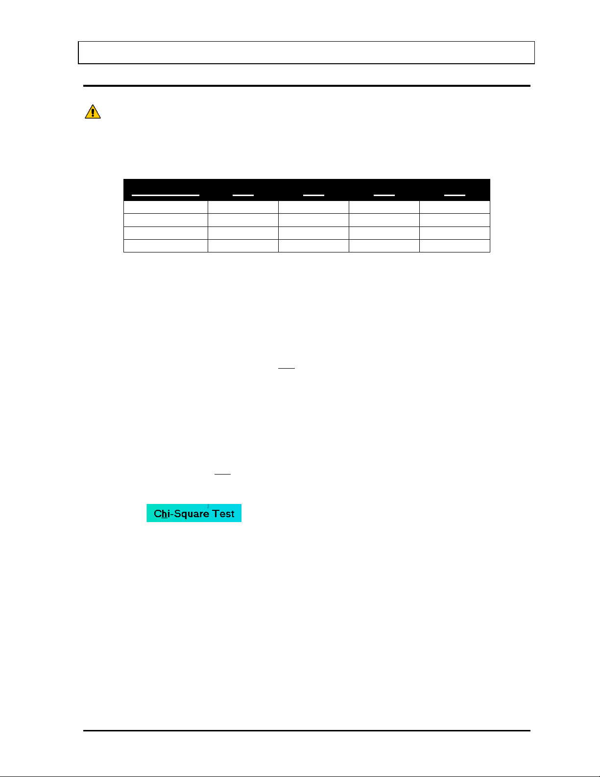
®
CAUTION: Calibration is recommended before making any measurements. Refer to
the AUTO CALIBRATION section on page 5-5.
5
.711
1.06
7.78
9.49
10
3.33
4.17
14.7
16.9
15
6.57
7.79
21.1
23.7
20
10.1
11.7
27.2
30.1
( )
∑
=
−=
n
i
avi
av
xx
x
1
2
2
1
χ
tsmeasuremen for the average
t measuremenfor counts where
nx
ix
av
i
=
=
( ) ( ) ( )
{ }
22
2
2
1
2
...
1
avnavav
av
xxxxxx
x
−++−+−=
χ
CAPINTEC, INC. CAPTUS
3000
CHI-SQUARE TEST
The Chi-Square Test provides a sensitive check of the overall counting performance of the
system. The software will use the 662 keV peak of your Cs137 source for the tests.
# Repetitions 0.95 0.90 0.10 0.05
In the table above, you can see that for a typical 10-repetition test, the Chi-Square value
should be between 3.33 and 16.9 for 95% of the time. Therefore, it is expected to be outside
this range 5% of the time. Also, because of the statistical nature of the Chi-Squared test, the
Chi-Square values should not remain exactly the same. They are expected to vary.
The Chi-Squared test value is calculated from the following equation:
This equation is the same as the following:
1. Click the button or press Alt+H on Figure 5-1 Quality Assurance
Main Screen. The screen appears as shown in Figure 5-16 Chi-Square Test Screen.
July 14 QUALITY ASSURANCE 5-15
Page 76
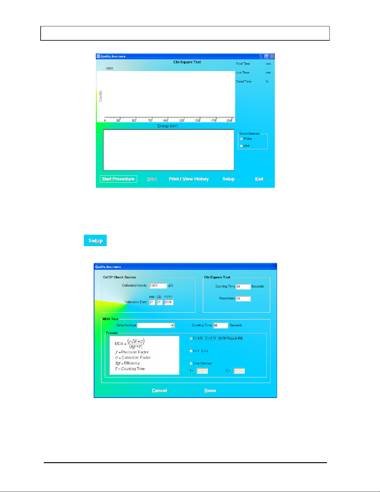
®
CAPINTEC, INC. CAPTUS
3000
Figure 5-16 Chi-Square Test Screen
2. Note that in the Select Detector frame, PROBE is selected by default. To change the
detector to Well, click the WELL radio button.
3. Click the button or press Alt+T. Figure 5-17 Quality Setup Screen will appear.
ONLY the Chi-Square Test frame values are used in this test.
Figure 5-17 Quality Setup Screen
5-16 QUALITY ASSURANCE July 14
Page 77
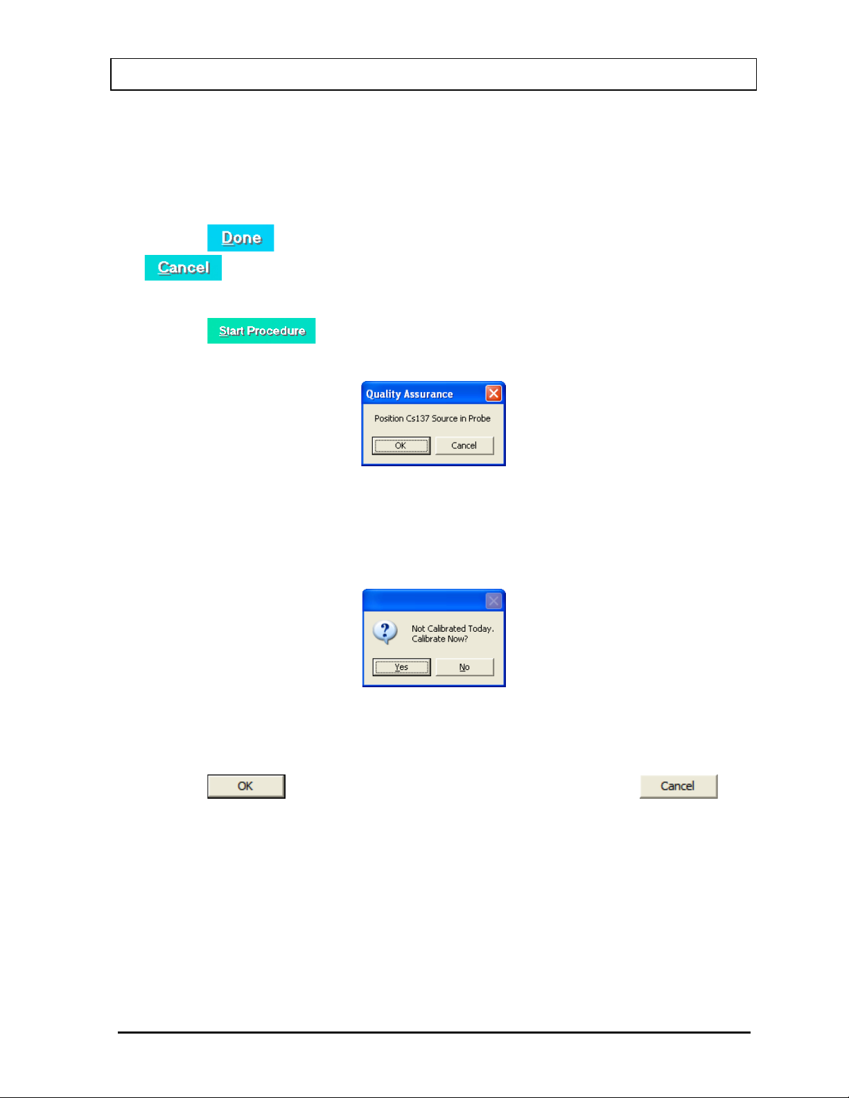
®
CAPINTEC, INC. CAPTUS
3000
4. To change the default values in Chi-Square Test frame in Setup, click in the text boxes
and input the new values.
Note: The Counting Time can be set between 2 and 9,999 seconds. The Repetitions
can be set between 5 and 20.
5. Click the button or press Alt+D to save the added information or click the
button or press Alt+C to cancel the changes and return to Figure 5-16 Chi-
Square Test Screen.
6. Click the button or press Alt+S to start the test. The screen appears as
shown in Figure 5-18.
Figure 5-18
Note: If calibration has not been performed using the selected detector, you will be
prompted with the screen as shown in Figure 5-19. After the calibration is
complete, the program will return to Figure 5-16 Chi-Squar e Test Screen.
Figure 5-19
7. Place the Cs137 source in the same position as for Auto Calibration and Constancy Test.
8. Click the button to proceed with the test. Otherwise, click the
button to stop the procedure.
If the procedure has started, then the screen as shown in Figure 5-20 appears. The
screen displays live spectra, measurement time (upper right corner) and the number of
repetitions remaining (middle right side).
July 14 QUALITY ASSURANCE 5-17
Page 78
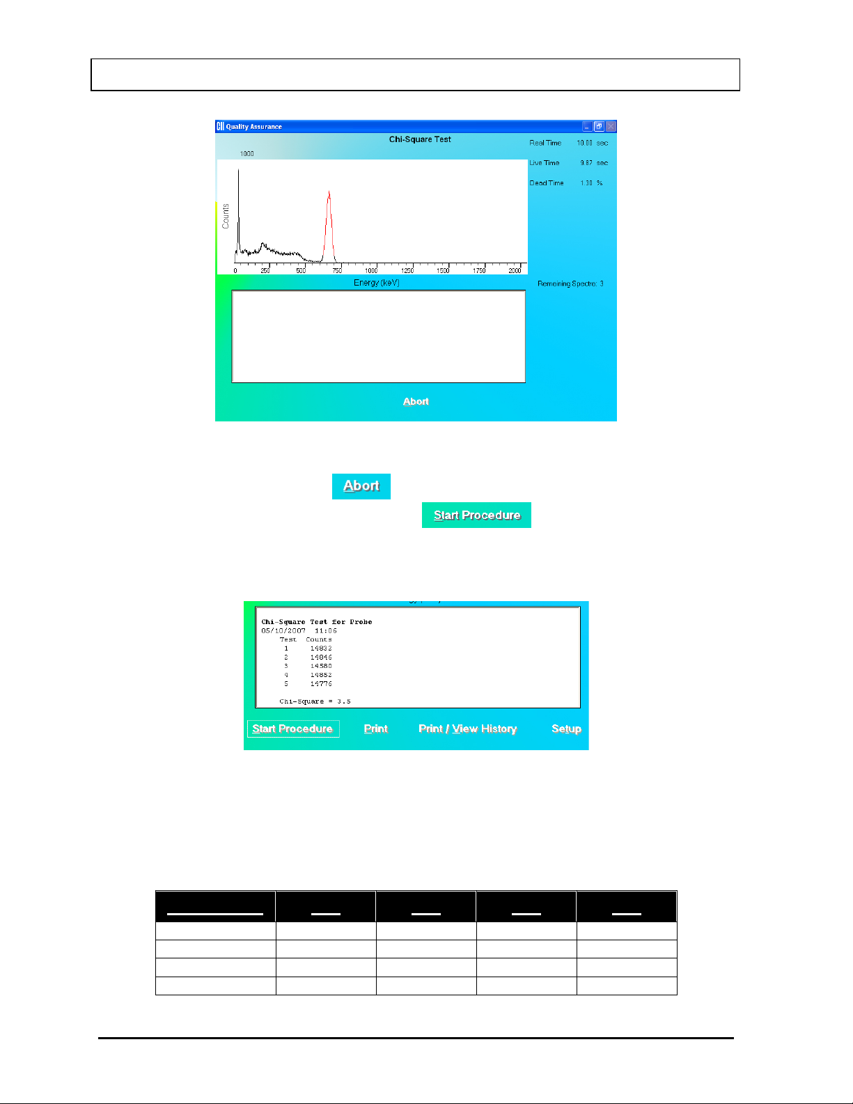
CAPINTEC, INC. CAPTUS
5
.711
1.06
7.78
9.49
10
3.33
4.17
14.7
16.9
15
6.57
7.79
21.1
23.7
20
10.1
11.7
27.2
30.1
Figure 5-20
®
3000
9. To stop the counting, click the button or press Alt+A. The collected data is
discarded. To re-start the process, click the button or press Alt+S.
10. After the test is completed, the results of the test appear in the results box similar to that
shown in Figure 5-21. Note the Chi-Square value.
Figure 5-21
Interpreting the Chi-Square Results – Chi-Square values are given in the following table
for 5, 10, 15, and 20 repetitions. The Chi-Square Test results should fall between the 0.95
and 0.05 probability values in the table below almost all of the time. The more stringent 0.90
and 0.10 values are given for reference.
# Repetitions 0.95 0.90 0.10 0.05
5-18 QUALITY ASSURANCE July 14
Page 79
CAPINTEC, INC. CAPTUS
QUICK TIPS:
PRINTING HISTORY section on page 5-24).
CAUTION: Calibration is recommended before making any measurements. Refer to
the AUTO CALIBRATION section on page 5-5.
If the Chi-Square value is out of range, check the following:
• The positioning of the rod source, especially for the Probe detector.
• Ensure that there are no other sources (including dosed patients) in the area.
If a problem is found with any of the two items above, then correct the problem and
repeat the Chi-Square Test.
In no problems are found with the above items, the out of range Chi-Square value may
indicate a problem with the counter/timer mechanism of the system or the detector itself.
Contact Capintec’s only Authorized Service Center for service.
• To print current results for record keeping, click the button or press
Alt+P on Constancy Test screen after the test is completed.
• To view or print results for all the Quality Assurance tests performed to date,
®
3000
click the button or press Alt+V (Refer to the
VIEWING AND
MDA TEST
This test measures counts and calculates activity in the ROI for the isotope selected in the
Setup. The measurement is performed with no isotope placed in the detector, which
therefore gives a value for the Minimum Detectable Activity (MDA).
1. Click the button or press Alt+M on Figure 5-1 Quality Assurance Main
Screen. Figure 5-22 MDA Test Screen will appear.
July 14 QUALITY ASSURANCE 5-19
Page 80
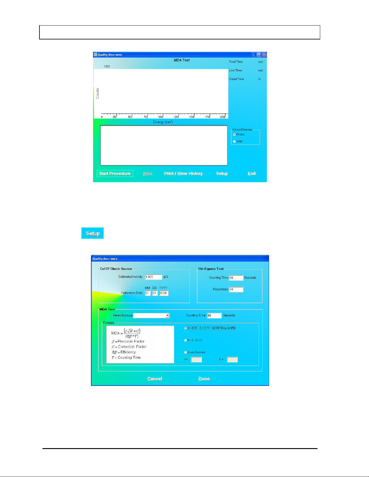
®
CAPINTEC, INC. CAPTUS
3000
Figure 5-22 MDA Test Screen
2. Note that in the Select Detector frame, PROBE is selected by default. To change the
detector to Well, click the WELL radio button.
3. Click the button or press Alt+T. Figure 5-23 Quality Setup Screen will appear.
Only the MDA Test frame values are used in this test.
Figure 5-23 Quality Setup Screen
4. To change the Cou nting Time click in the text box and input the new value.
Note: The Counting Time can be set between 1 and 9,999 seconds.
5-20 QUALITY ASSURANCE July 14
Page 81
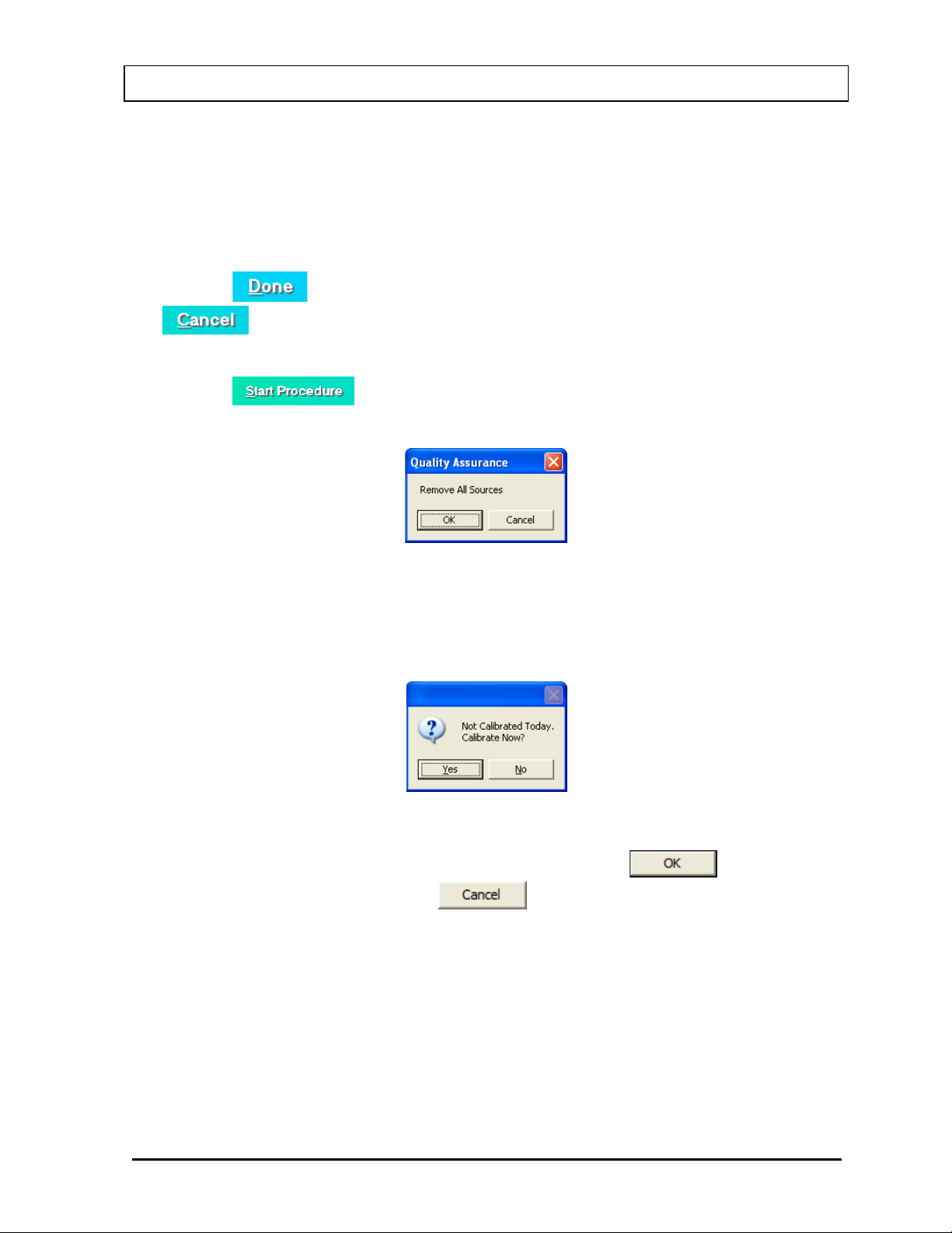
®
CAPINTEC, INC. CAPTUS
3000
5. To select another isotope, click in the Selected Isotope drop-down box and click on the
desired isotope to select it. This sets a new ROI for count measurement.
6. To alter values used in the formula for MDA calculation, click in the desired radio button
in Formula frame.
7. Click the button or press Alt+D to save the added information or click the
button or press Alt+C to cancel the changes and return to Figure 5-22 MDA
Test Screen.
8. Click the button or press Alt+S to start the test. The screen appears as
shown in Figure 5-24.
Figure 5-24
Note: If calibration has not been performed using the selected detector, you will be
prompted with the screen as shown in Figure 5-25. After the calibration is
complete, the program will return to Figure 5-22 MDA Test Screen.
Figure 5-25
9. Remove any radioactive source from the vicinity and click the button to
proceed with the test. Else, click the button to stop the procedure.
10. When the measurement is completed, the screen appears similar to that shown in Figure
5-26 displaying the Minimum Detectable Activity (MDA) measured in the selected
isotope’s ROI.
July 14 QUALITY ASSURANCE 5-21
Page 82
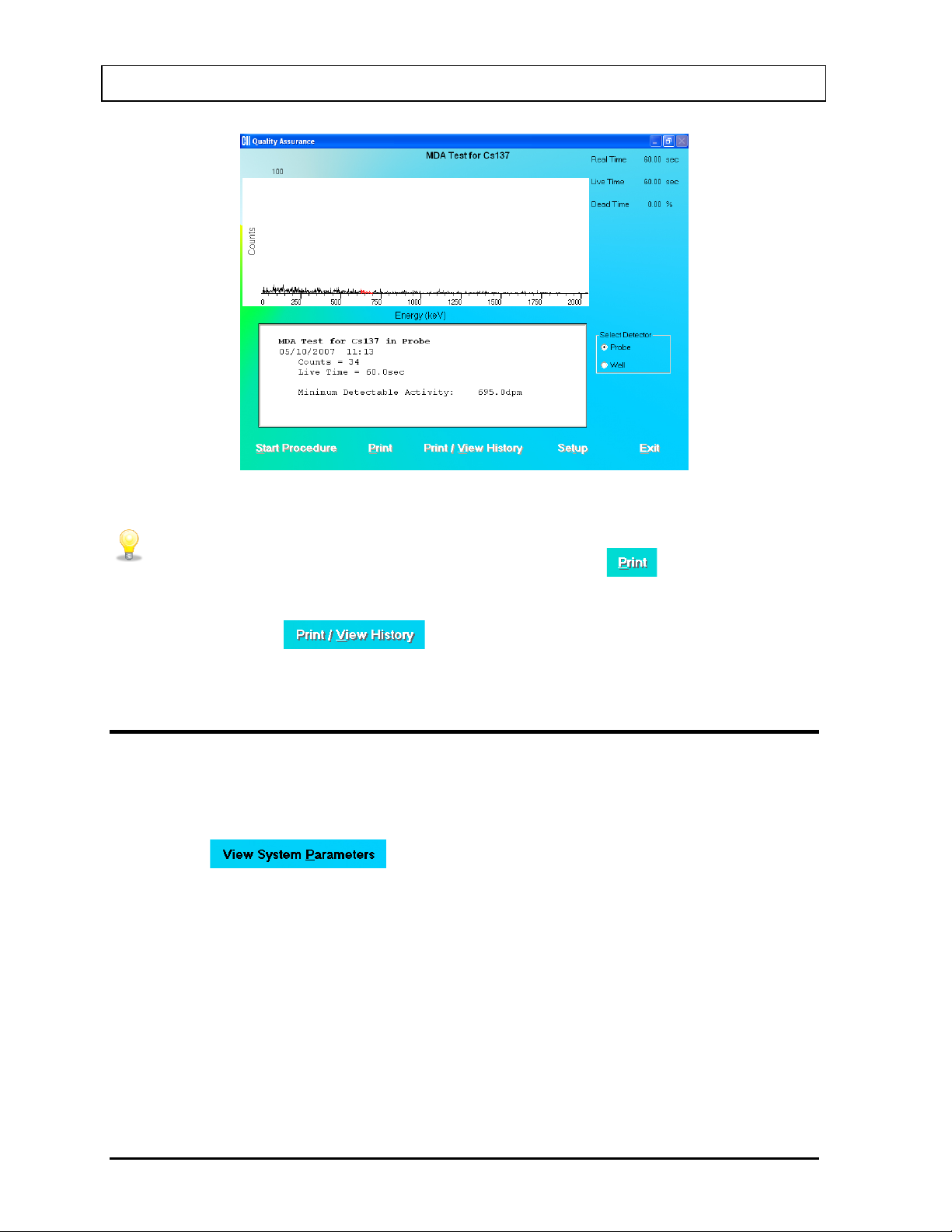
CAPINTEC, INC. CAPTUS
QUICK TIPS:
PRINTING HISTORY section on page 5-24).
Figure 5-26
®
3000
• To print current results for record keeping, click the button or press
Alt+P on MDA Test screen after the test is completed.
• To view or print results for all the Quality Assurance tests performed to date,
click the button or press Alt+V (Refer to the
VIEWING AND
VIEWING SYSTEM PARAMETERS
This function provides access to all the parameters used for the measurements and
calculations of results in all procedures (Thyroid Uptake, Lab Tests, Wipe Test, QA Tests
etc.) provided by the CAPTUS
1. Click the button or press Alt+P on Figure 5-1 Quality Assurance
Main Screen. The screen appears similar to that shown in Figure 5-27. You may scroll
down to see all of the parameters. The system details appear at the top followed by the
Quality Assurance parameters. Below that, setup values are listed for each type of
procedure.
®
3000 system.
5-22 QUALITY ASSURANCE July 14
Page 83
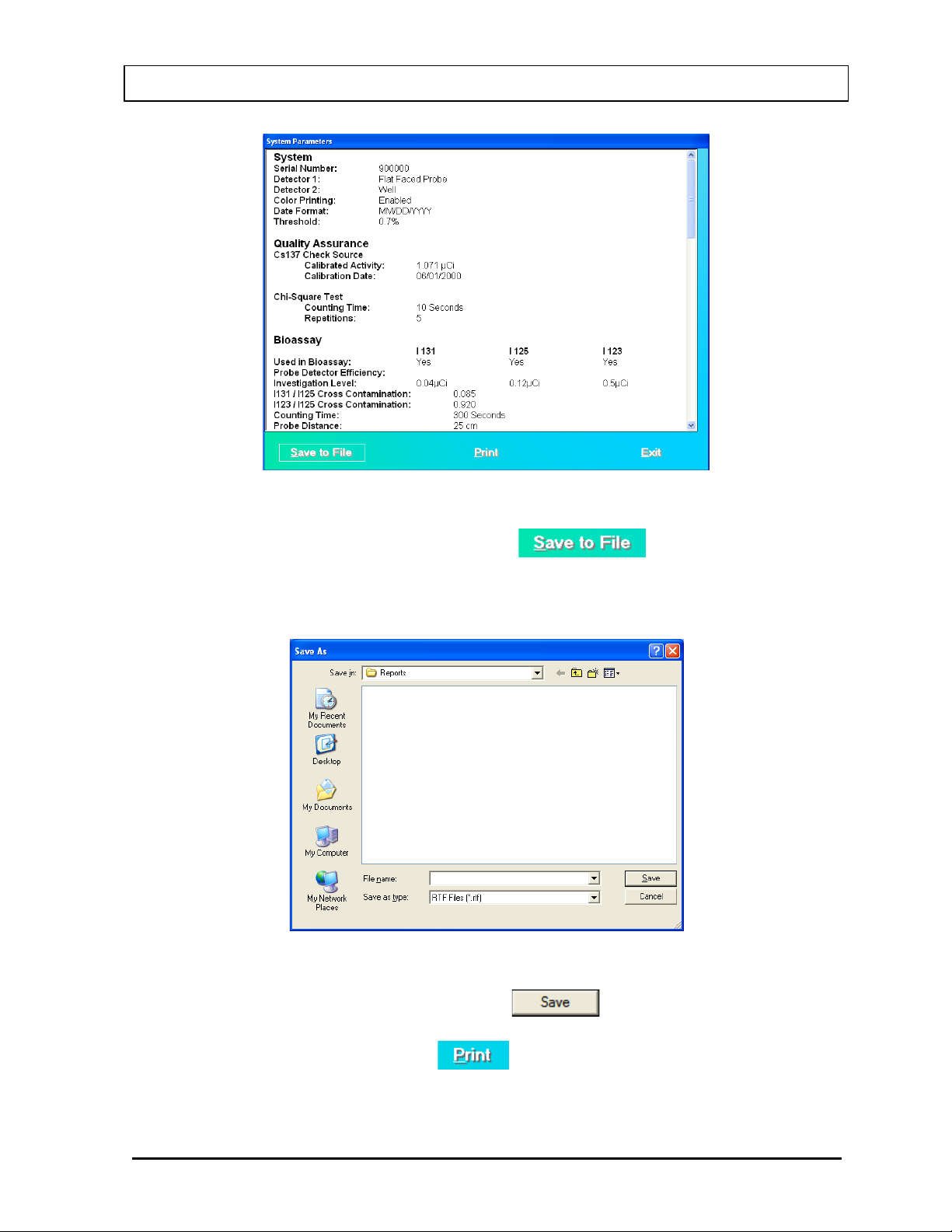
CAPINTEC, INC. CAPTUS
Figure 5-27
®
3000
2. To save all these parameters to a file, click the button or press Alt+S.
The Save As screen appears as shown in Figure 5-28. The default folder is Reports in
CAPTUS
®
3000 folder. Data is saved in rich text format (.rtf), which may be viewed in a
word processor (such as WordPad).
Figure 5-28
3. Type in an appropriate file name and click the butt on or press Alt+S.
4. To print all the parameters, click the button or press Alt+P.
July 14 QUALITY ASSURANCE 5-23
Page 84
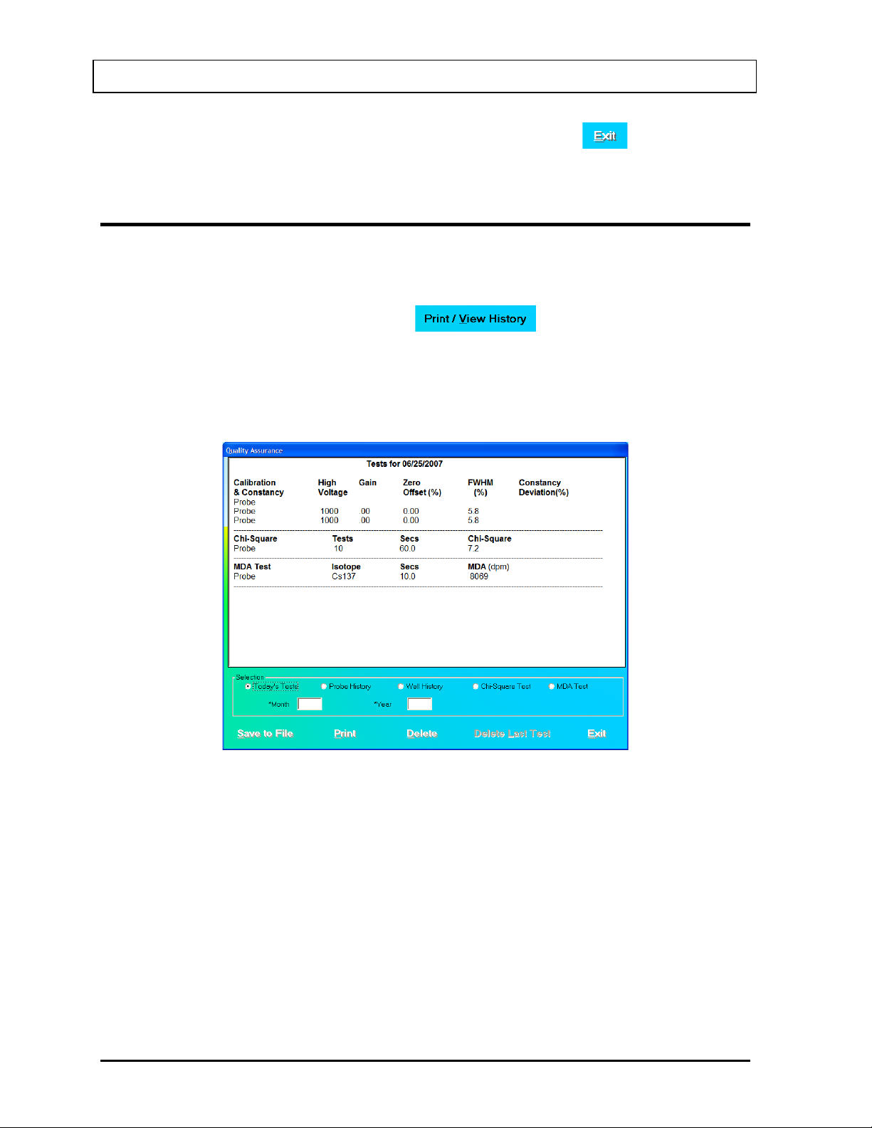
®
CAPINTEC, INC. CAPTUS
3000
5. To return to Figure 5-1 Quality Assurance Main Screen, click the button or press
Alt+E.
VIEWING AND PRINTING HISTORY
This function provides a history of all the QA Tests performed to date. It can be accessed
from Figure 5-1 Quality Assurance Main Screen or any one of the QA Test screens.
1. To access the QA Tests history, click the button or press Alt+V on
Figure 5-1 Quality Assurance Main Screen or any one of the QA Test screens. The
screen appears similar to that shown in Figure 5-29. There are various ways of viewing
the history. Note that the default selection is Today’s Tests. All of the tests performed on
that day appear with the date at the top. When the selection is changed, the screen
changes accordingly.
Figure 5-29
2. To view all the results of each Auto Calibration and Constancy Test performed to date on
the Probe or Well detector, click the appropriate radio button for the Probe History or
Well History.
To view only the results from a specific month and year,
• In the Month text box, input the month in numeric format (1 to 12).
• In the Year text box, input the year in 4-digit year format (2000 to 2050).
• Click on the Probe History or Well History radio button to display the selected data.
3. To view all the results of each Chi-Square Test or MDA Test performed to date, click the
appropriate radio button for that test.
5-24 QUALITY ASSURANCE July 14
Page 85
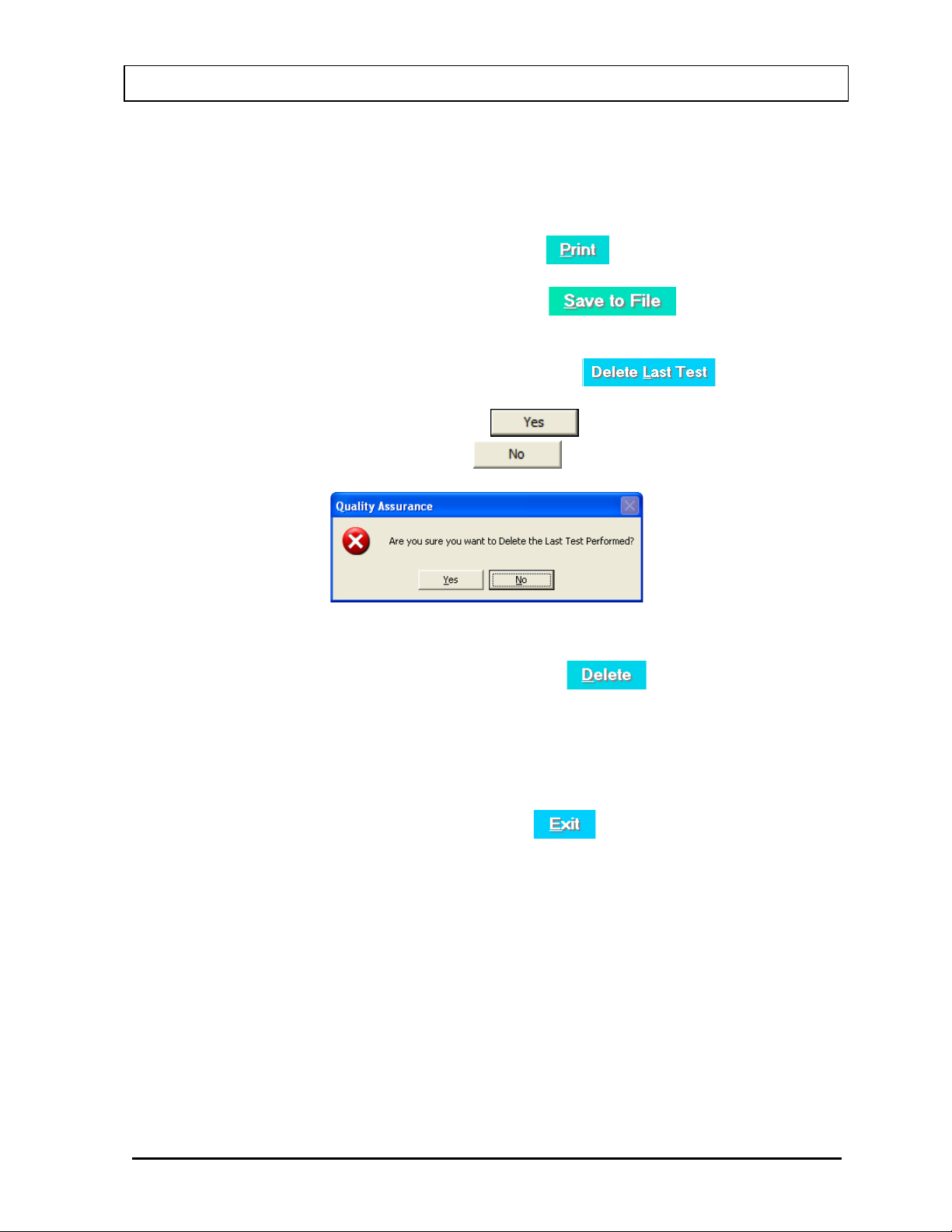
®
CAPINTEC, INC. CAPTUS
3000
To view only the results from a specific month and year,
• In the Month text box, input the month in numeric format (1 to 12).
• In the Year text box, input the year in 4-digit year format (2000 to 2050).
• Click on the Chi-Square Test or MDA Test radio button to display the selected data.
4. To print the results on the current screen, click the button or press Alt+P.
5. To save the results on the current screen, click the button or press
Alt+S.
6. To delete the latest test on the current screen, click the button or press
Alt+L. This function is not accessible when Today’s Tests is selected. The screen
appears as shown in Figure 5-30. Click the button or press the Y key to
confirm the deletion. Otherwise, click the button or press the N key.
Figure 5-30
7. To delete all the tests on the current screen, click the button or press Alt+D.
You will be prompted to confirm the deletion as shown in Figure 5-30 above.
Note: You may want to archive the QA data before deleting the histor y. Refer to
CHAPTER 14: ARCHIVE.
8. To exit the Print/View History screen and return to Figure 5-1 Quality Assurance Main
Screen or the previous QA Test screen, click the button or press Alt+E.
July 14 QUALITY ASSURANCE 5-25
Page 86

CAPINTEC, INC. CAPTUS® 3000
This page intentionally left blank.
Page 87

CAPINTEC, INC. CAPTUS® 3000
CAUTION: To ensure optimum performance of CAPTUS® 3000, before using
outlined in CHAPTER 4: GENERAL SETUP.
CHAPTER 6
ISOTOPES
INTRODUCTION ............................................................................................. 6-1
VIEWING AND PRINTING ISOTOPE LIBRARY ............................................. 6-2
ADDING A NEW ISOTOPE TO THE LIBRARY .............................................. 6-3
EDITING ISOTOPE INFORMATION ............................................................... 6-4
DELETING AN ISOTOPE ................................................................................ 6-5
MEASURING EFFICIENCY ............................................................................. 6-5
ENTERING EFFICIENCY ................................................................................ 6-9
the Isotopes module, perform the System Setup Procedures as
INTRODUCTION
The CAPTUS® 3000 has an extensive reference library of at least 76 isotopes that contains
information on their half-lives, major energy peaks, and known efficiencies. This information
is used in the identification of isotope peaks in MCA, Wipe Test module, radioactive decay
corrections and measurement of efficiencies. The user may add new isotopes to this list if
required.
To access the Isotopes module, click the
3000 Main screen. Figure 6-1 Isotopes Main Screen will appear.
button or press Alt+I on the CAPTUS®
November 13 ISOTOPES 6-1
Page 88
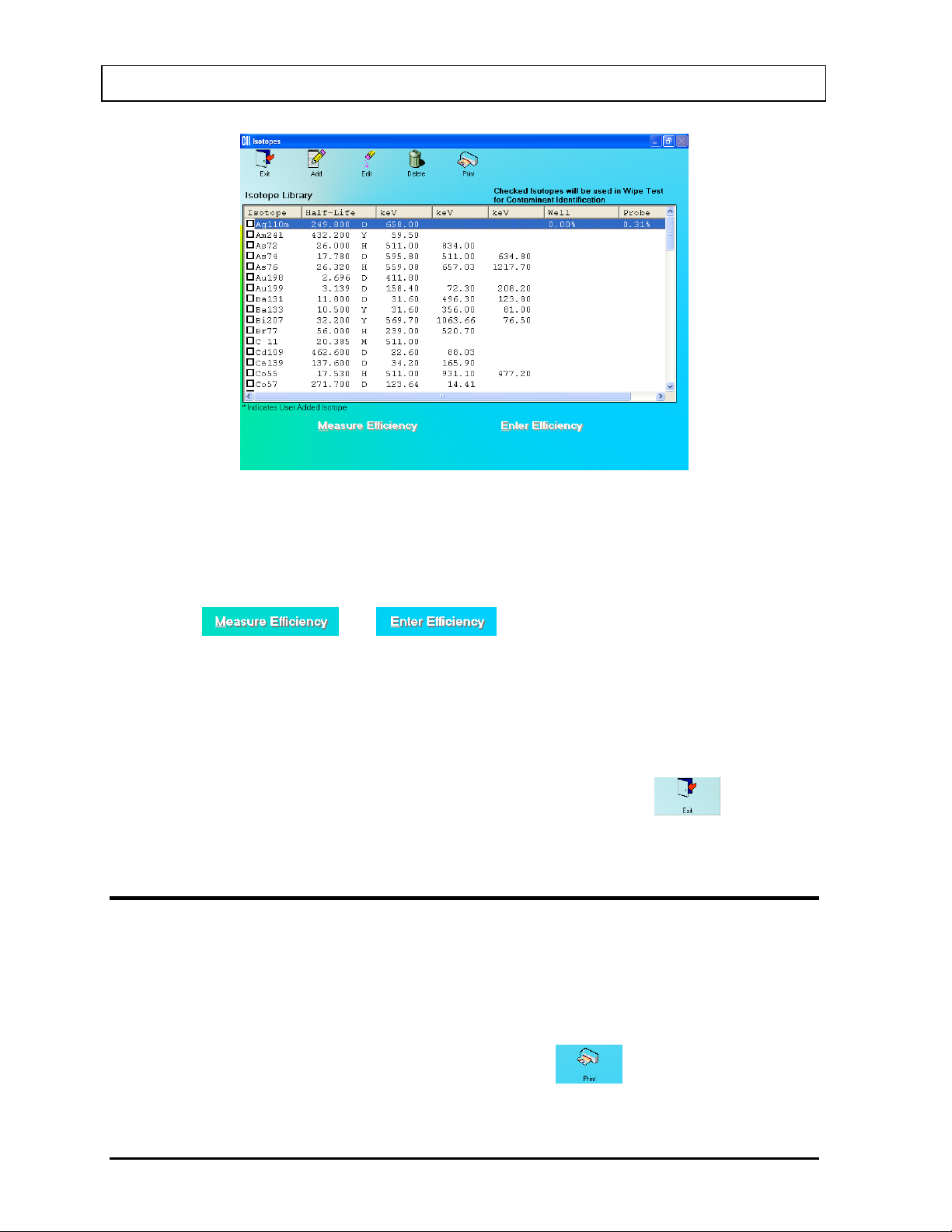
CAPINTEC, INC. CAPTUS® 3000
Figure 6-1 Isotopes Main Screen
The Isotope Library box in the middle of the screen lists the isotopes alphabetically, with
their respective Half-Lives in minutes (M), hours (H), days (D) or years (Y), keV (for major
energy peaks), and Well and Probe efficiencies, if known. The icons at the top provide
functions for adding new isotopes, editing and deleting the added isotopes and printing the
library. The
and buttons at the bottom of the screen let
you measure efficiency or enter a new efficiency value respectively for the selected isotope.
Note: At the top right of the Isotope Library box, the message “Checked Isotopes will be
used in Wipe Test for Contaminant Identification” is displayed. All isotopes with a
check mark in their check box will have their energy peaks used for isotope
identification in the Wipe Test module.
To return to th e CAPTUS
®
3000 Main screen from this screen, click the icon or
press the Esc key.
VIEWING AND PRINTING ISOTOPE LIBRARY
1. To view all the isotopes, scroll up or down the list in Isotopes Library box using the
scroll bar or use Page Down, Page Up, and keys.
2. To locate an isotope, press the first letter of the isotope to bring it into view. The first
isotope with that letter is highlighted. Use key to move further down if necessary.
3. To print the entire contents of Isotope Library, click the
icon.
6-2 ISOTOPES November 13
Page 89
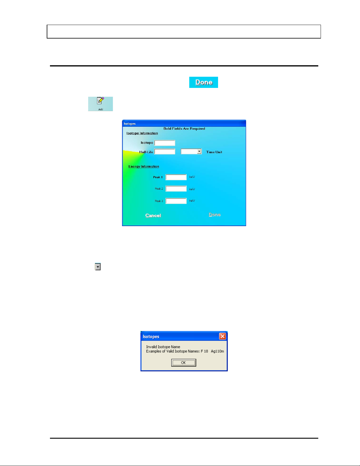
CAPINTEC, INC. CAPTUS® 3000
ADDING A NEW ISOTOPE TO THE LIBRARY
Note: All fields in bold are required before the button will be enabled.
1. Click the
icon on Figure 6-1 Isotopes Main Screen. Figure 6-2 will appear.
Figure 6-2
2. Click in the appropriate text box under Isotope Information to input the isotope name
and its half-life. Select a time unit for the entered half-life from the drop-down list by
clicking the
arrow button in the Time Unit text box.
Note: An isotope name can be entered only in a specific format; which is the symbol of
the element (alphabetical character) followed by the atomic mass (number). If the
element symbol is one character, be sure to insert a space between the character
and the number. If the element symbol is two characters, do not insert a space
between the character and numbers. If entered otherwise, an error mess age will
appear as shown in Figure 6-3.
Figure 6-3
3. Click in the text boxes under Energy Information and input the peak energy values in
keV. At least one peak value must be input.
November 13 ISOTOPES 6-3
Page 90
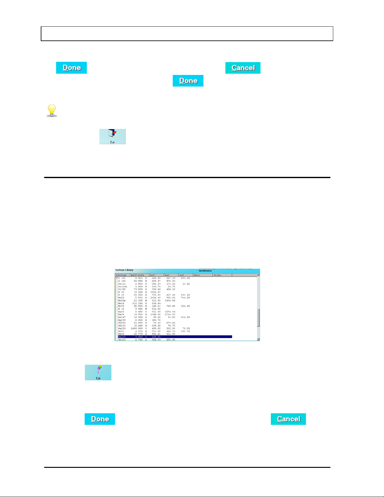
CAPINTEC, INC. CAPTUS® 3000
QUICK TIPS:
4. To save the added information and return to the Isotopes Main screen, click the
button or press Alt+D. Alternatively, click the button or press Alt+C
to return without saving. Note that the
button is enabled only after all of the
required fields are entered.
• To move between data fields use the Tab key.
• To return to CAPTUS
the
icon or press the ESC key.
®
3000 Main screen from the Isotopes Main screen, click
EDITING ISOTOPE INFORMATION
Note: Only user added isotopes can be edited. Information in the system’s pre-existing
Isotope Library cannot be altered.
1. If the isotope to be edited is out of view in the Isotope Library box on Figure 6-1
Isotopes Main Screen, scroll up or down the list in Isotopes Library box using the scroll
bar or use Page Down, Page Up, and keys or press the first letter of the isotope to
bring it into view.
2. Click on the isotope to select it (highlighted) for editing as shown in Figure 6-4.
Figure 6-4
3. Click the
icon. Figure 6-2 will appear.
4. Click in the text box or use the Tab key to move around. Type over the existing
information.
5. Click the
button or press Alt+D to save changes or click the button
or press Alt+C to cancel the changes and return to Figure 6-1 Isotopes Main Screen.
6-4 ISOTOPES November 13
Page 91
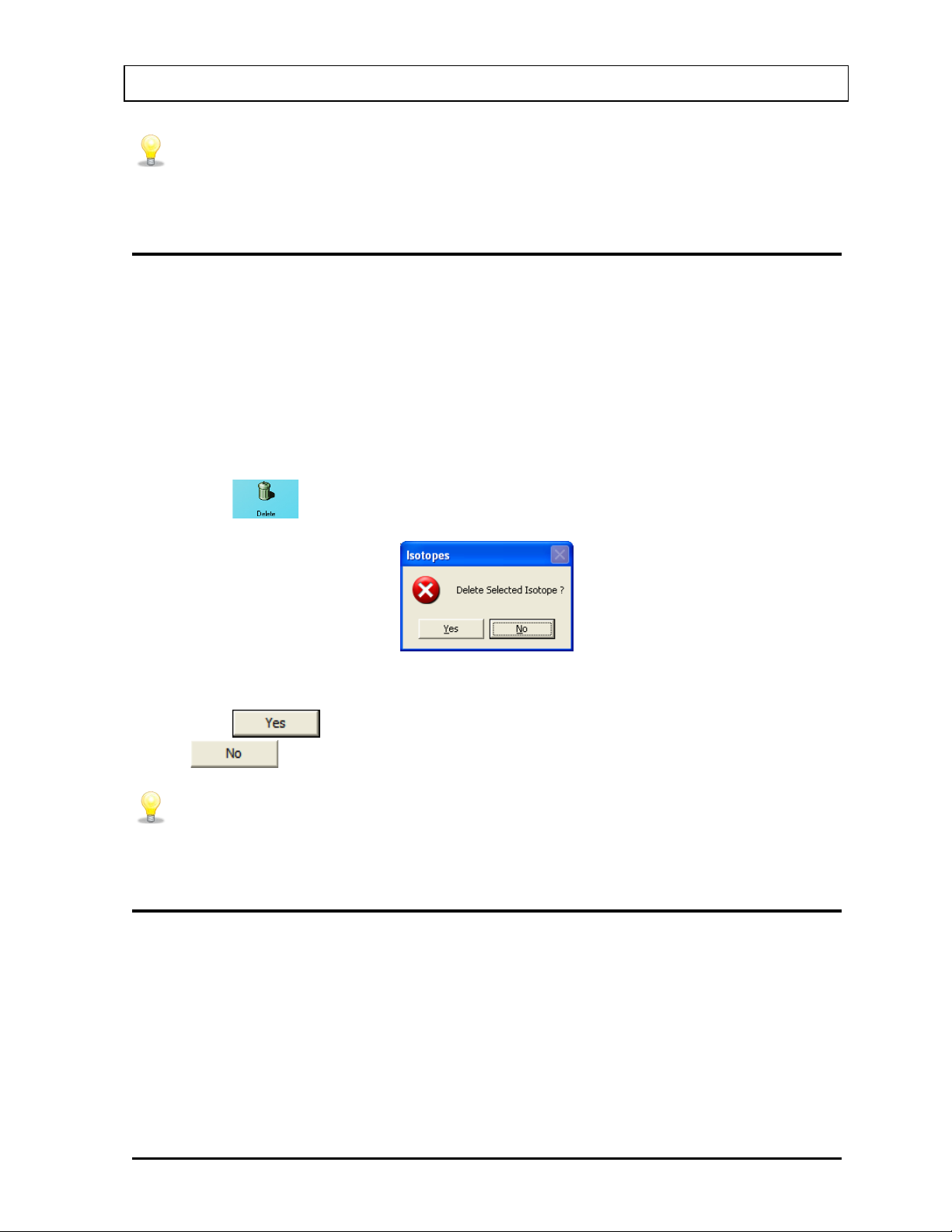
CAPINTEC, INC. CAPTUS® 3000
QUICK TIPS:
keys or press the first letter of the isotope to bring it into view.
QUICK TIPS:
keys or press the first letter of the isotope to bring it into view.
• To locate an isotope, use the scroll bar, use Page Down, Page Up, and
DELETING AN ISOTOPE
Note: Only user added isotopes can be deleted. Isotopes in the system’s pre-existing
Isotope Library cannot be deleted.
1. If the isotope to be deleted is out of view in the Isotope Library box on Figure 6-1
Isotopes Main Screen, scroll up or down the list in Isotopes Library box using the scroll
bar or use Page Down, Page Up, and keys or press the first letter of the isotope to
bring it into view.
2. Click on the isotope to select it (highlighted) for deleting as shown in Figure 6-4.
3. Click the
icon. The screen appears as shown in Figure 6-5.
Figure 6-5
4. Click the button or press the Y key to confirm the deletion. Alternatively, click
the
button or press the N key to cancel the deletion.
• To locate an isotope, use the scroll bar, use Page Down, Page Up, and
MEASURING EFFICIENCY
1. If the isotope to be measured is out of view in the Isotope Library box on Figure 6-1
Isotopes Main Screen, scroll up or down the list in Isotopes Library box using the scroll
bar or use Page Down, Page Up, and keys or press the first letter of the isotope to
bring it into view.
2. Click on the isotope to select it (highlighted) for measuring as shown in Figure 6-4.
November 13 ISOTOPES 6-5
Page 92
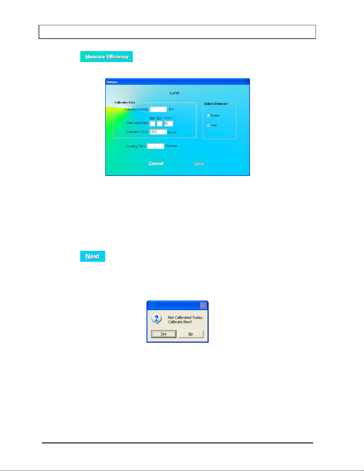
CAPINTEC, INC. CAPTUS® 3000
3. Click the button or press Alt+M. The screen appears as shown in
Figure 6-6 with the name of the isotope at the top.
Figure 6-6
4. Click in the text box or use the Tab key to move around. Input the Calibration Activity,
Calibration Date and Calibration Time from the source label and Counting Time
desired in seconds.
5. To change the detector from PROBE to WELL, click in the appropriate radio button in the
Select Detector frame.
6. Click the
button or press Alt+N. The screen appears as shown in Figure 6-8.
Note: If calibration has not been performed for the current day for the selected detector,
you will be prompted with the screen as shown in Figure 6-7. If calibration is
performed now, t he progr am will return to Figure 6-8 after calibration is complete.
Figure 6-7
6-6 ISOTOPES November 13
Page 93
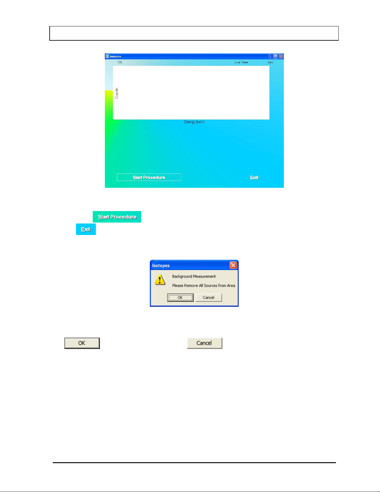
CAPINTEC, INC. CAPTUS® 3000
Figure 6-8
7. Click the
the
button or press Alt+E to return to Figure 6-1 Isotopes Main Screen.
button or press Alt+S to start measurements. Alternatively, click
8. When the procedure is started, the screen appears as shown in Figure 6-9.
Figure 6-9
To begin counting, verify that there are no radioactive sources nearby and click the
button. Otherwise, click the button to return to the measurement
screen. The Data Acquisition screen appears as shown in Figure 6-10.
November 13 ISOTOPES 6-7
Page 94
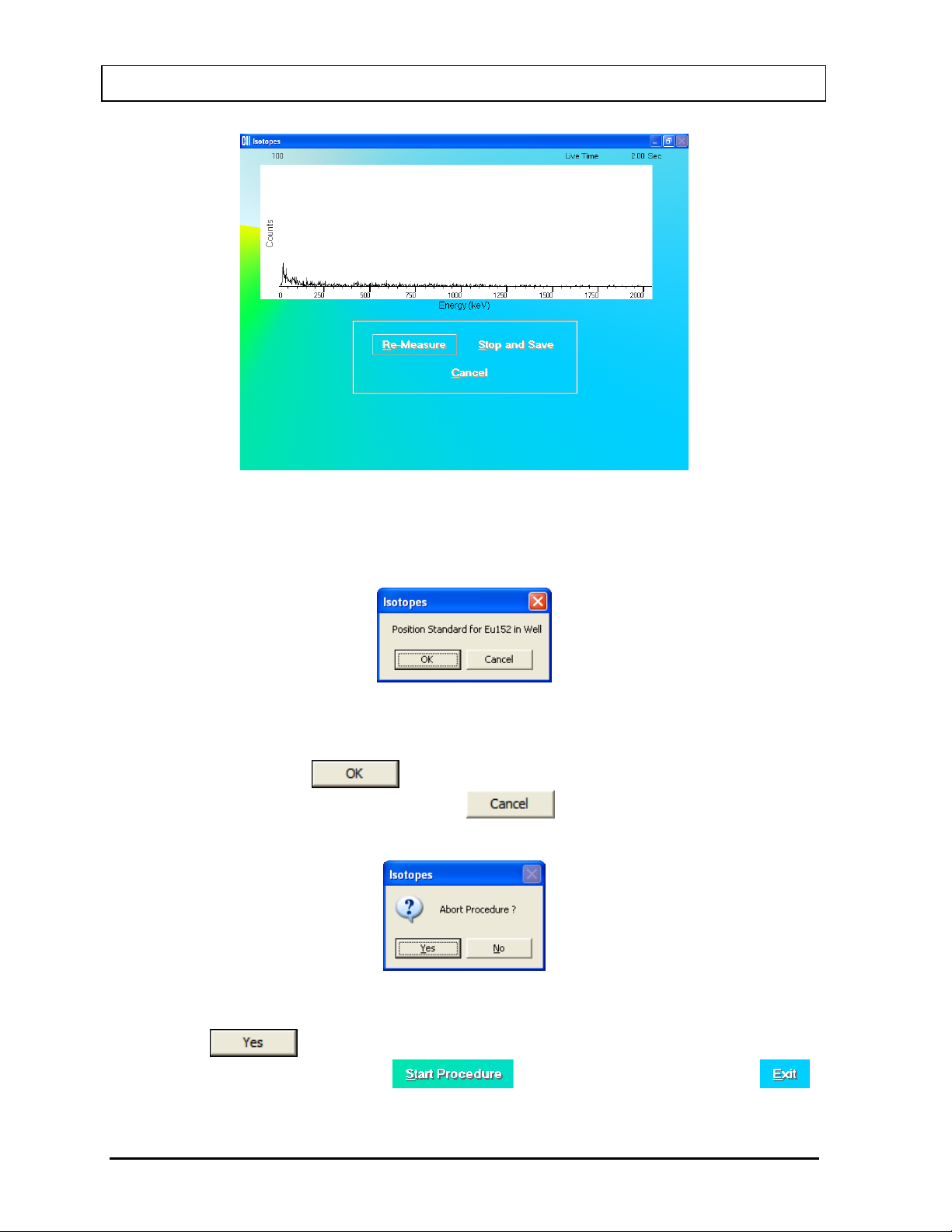
CAPINTEC, INC. CAPTUS® 3000
Figure 6-10
9. Next, the screen appears as shown in Figure 6-11, prompting you to measure the isotope
selected for efficiency measurement.
Figure 6-11
To measure the isotope, place the isotope standard in the Probe or Well as the message
indicates and click the
above. To stop the measurement, click the
button. Data collection begins as shown in Figure 6-10
button. The screen then appears
as shown in Figure 6-12.
Figure 6-12
Click the button or press the Y key to end the procedure. The screen appears
as shown in Figure 6-8. Click the
button to start again or click the
button to quit.
6-8 ISOTOPES November 13
Page 95
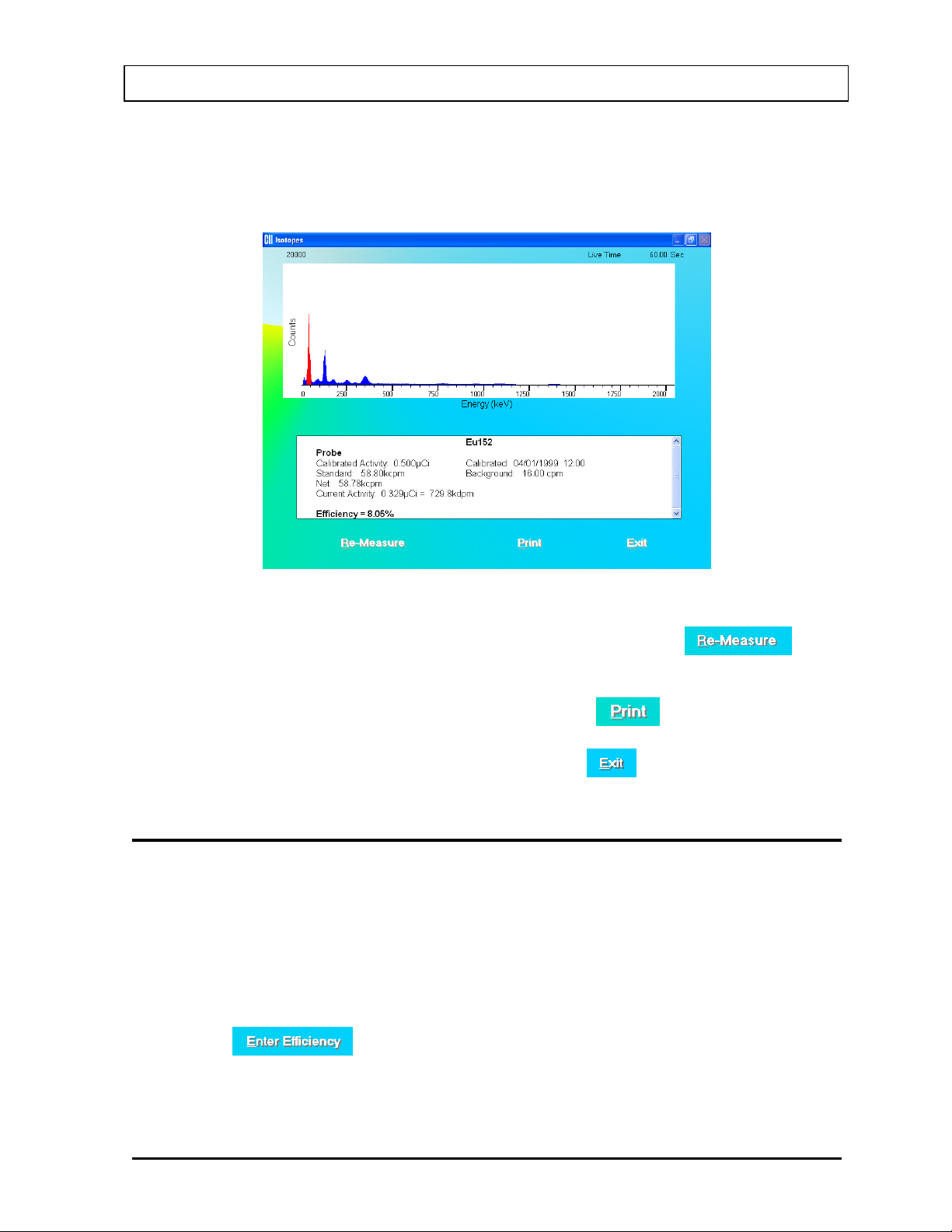
CAPINTEC, INC. CAPTUS® 3000
10. After the measurement is completed, the screen appears similar to that shown in Figure
6-13. The results in the lower part of the screen show measured counts and calculated
values for activity and efficiency.
Figure 6-13
11. To repeat the efficiency measurement for the same isotope, click the
button or press Alt+R. Steps 8 thru 10 are repeated.
12. To print the spectrum and results on the screen, click the
button or press Alt+P.
13. To exit and return to the main Isotopes screen, click the
button or press Alt+E.
ENTERING EFFICIENCY
1. If the isotope whose Efficiency is to be entered is out of view in the Isotope Library box
on Figure 6-1 Isotopes Main Screen, scroll up or down the list in Isotopes Library box
using the scroll bar or use Page Down, Page Up, and keys or press the f i rst letter of
the isotope to bring it into view.
2. Click on the isotope to select it (highlighted) for entering efficiency as shown in Figure 6-
4.
3. Click the
button or press Alt+E. The screen appears as shown in Figure
6-14. The name of the isotope appears at the top. Efficiency values for Well and Probe
may or may not already exist.
November 13 ISOTOPES 6-9
Page 96

CAPINTEC, INC. CAPTUS® 3000
QUICK TIPS:
keys or press the first letter of the isotope to bring it into view.
Figure 6-14
4. Click in the appropriate text box or use the Tab key to move around. Type in the new
efficiency value for Well or Probe or both as needed.
5. Click the
button or press Alt+D to save changes or click the button
or press Alt+C to cancel the changes and return to Figure 6-1 Isotopes Main Screen.
• To locate an isotope, use the scroll bar, use Page Down, Page Up, and
6-10 ISOTOPES November 13
Page 97

CAPINTEC, INC. CAPTUS® 3000
CAUTION: To ensure optimum performance of CAPTUS® 3000, before using the
outlined in CHAPTER 4: GENERAL SETUP.
%100
Hrs 6at Activity
Capsule
Hrs 6at Activity Patient
Hrs
6at
Uptake ×=
CHAPTER 7
THYROID UPTAKE
INTRODUCTION ............................................................................................. 7-1
QUICK STEP GUIDE FOR THYROID UPT AKE PROCEDURE ...................... 7-3
MEASUREMENT PROTOCOLS ..................................................................... 7-3
Counting Methods ...................................................................................... 7-3
Dose Administration .................................................................................. 7-4
Adding Protocols ....................................................................................... 7-5
Editing Protocols ........................................................................................ 7-7
Deleting Protocols ...................................................................................... 7-8
Printing Protocol Report ........................................................................... 7-10
PATIENT INFORMATION .............................................................................. 7-10
Adding Patients ......................................................................................... 7-10
Viewing Patient Information ..................................................................... 7-12
Editing Patient Information ....................................................................... 7-13
Deleting Patient Records .......................................................................... 7-15
VIEWING AND CHANGING THE SETUP ...................................................... 7-15
MAKING MEASUREMENTS .......................................................................... 7-17
Counting Selected Patient ........................................................................ 7-19
Administering Dose .................................................................................. 7-23
RESULTS ....................................................................................................... 7-24
Patients Reports ........................................................................................ 7-24
Thyroid Uptake module, perform the System Setup Procedures as
INTRODUCTION
Thyroid Uptake is a measurement of the ratio of the amount of radioactive material
concentrated in the thyroid gland to the amount of radioactive material administered to the
patient. The results of the procedure are expressed as a percentage. Dose Administration
time being regarded as 0 hours,
Thyroid Uptake measurements are generally used to determine conditions of
hyperthyroidism. High uptake results are found in Graves disease, toxic nodular goiter, and
stimulator secreting tumors or can be TSH-induced. Low uptake results are found with
thyroid hormone secretion in ectopic tumors, hormonal release in thyroid injury, after intake
November 13 THYROID UPTAKE 7-1
Page 98
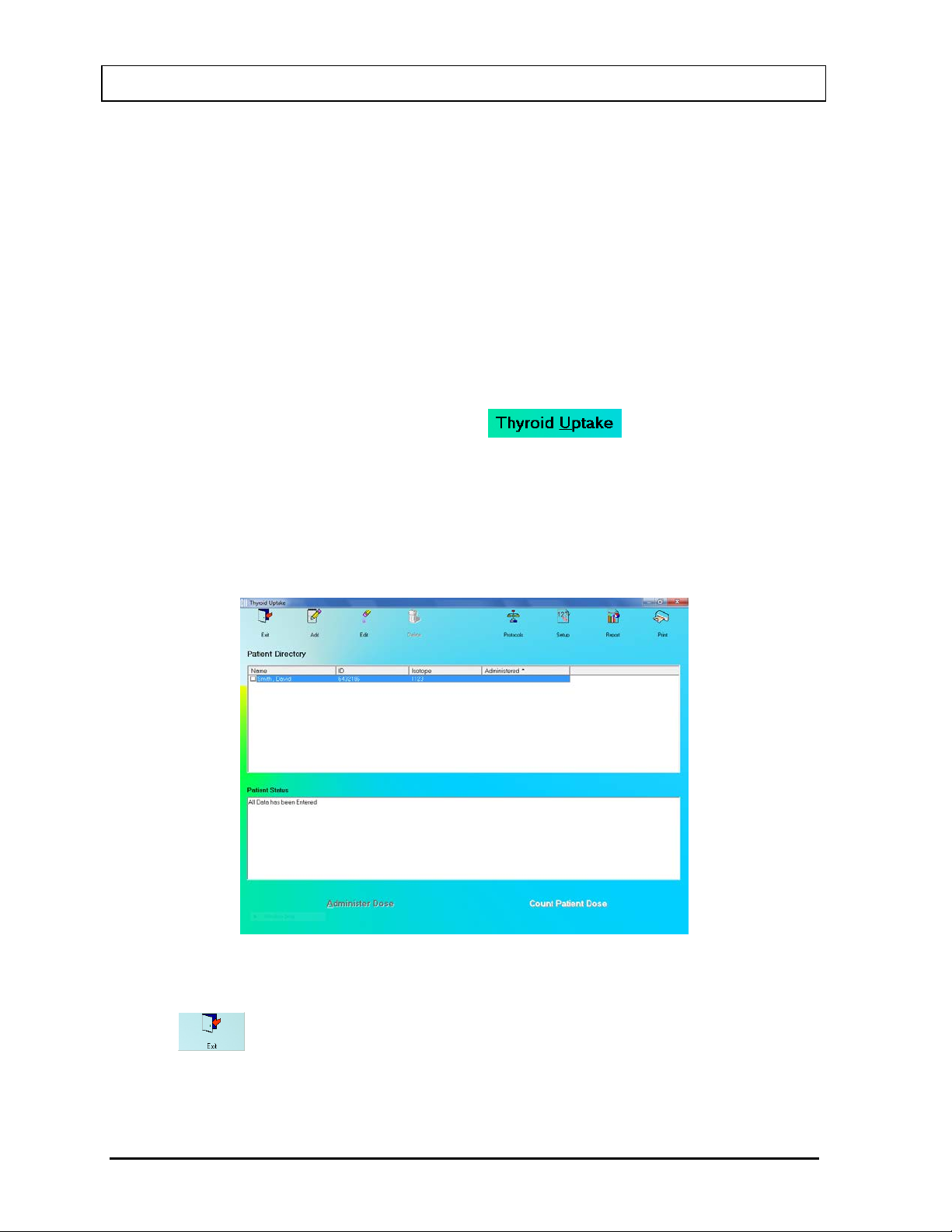
CAPINTEC, INC. CAPTUS® 3000
of thyroid hormone, or Jod-Basedow disease. During the treatment of thyroid cancer by I-131
ablation, uptake measurements are used to monitor thyroid activity.
The CAPTUS
data for both the administered dosage and the patient, decay correct all count data, calculate
thyroid uptake results, and store all of this information. Regions of Interest have been defined
for three isotopes, I-131, I-123, or Tc99m. If normal values have been entered in the setup,
then uptake results exceeding these values will be flagged. All of the patient information may
be printed. The thyroid uptake software has been designed to accommodate a variety of
different counting protocols, using either capsules or liquid dosages.
Note: In the following sections of the chapter, the word capsule will be used for either a
capsule or liquid dosage.
®
3000 system will store patient demographic and dosage information, count
To access the Thyroid Uptake functions, click the
the CAPTUS
®
3000 Main screen. Figure 7-1 Main Thyroid Uptake Screen will appear. The
button or press Alt+U on
Patient Directory box will be empty if there are no existing patients in the database. This
box will display the patient’s name, ID, administered isotope (if known) and the time and date
of dose administration (if already done). By default, patients are sorted by their dose
administration time, latest one first. The Patient Status box below the Patient Directory box
shows the current status of the selected patient. If the uptake procedure has been started,
the updated results will be displayed here.
Figure 7-1 Main Thyroid Uptake Screen
To return to th e CAPTUS
click the
icon or press the Esc key.
®
3000 Main screen from Figure 7-1 Main Thyroid Uptake Screen,
7-2 THYROID UPTAKE November 13
Page 99

CAPINTEC, INC. CAPTUS® 3000
Note: At least one measurement protocol must be set up before any patient can be added
to the Patient Dir ectory or any other function can be accessed from Figure 7-1 Main
Thyroid Uptake Screen.
QUICK STEP GUIDE FOR THYROID UPTAKE PROCEDURE
1. Set up a protocol for measurement (refer to Adding Protocols on page 7-5).
2. Add all the required patient information and dosage information (refer to Adding Patients
on page 7-10).
3. If the counting method selected in protocol is Decay Correct Administered Dose (refer to
MAKING MEASUREMENTS on page 7-17), count each capsule for an initial capsule
count before the patient arrives.
4. If needed, measure pre-dose patient when the patient arrives.
5. Administer the capsule(s) to the patient. Record the administered time (refer to Dose
Administration on page 7-4).
6. Count the patient after a desired uptake time (refer to Counting Selected Patient on
page 7-19).
7. Print the patient report if needed (refer to Patients Reports on page 7-24).
MEASUREMENT PROTOCOLS
Protocols need to be set up to select the method of measurement and dose administration to
the patient (refer to Adding Protocols on page 7-5).
Counting Methods
There are two counting methods that can be used as the measurement protocol:
1. Decay Correct Administered Dose
In this method, a single capsule is used.
• Measure the capsule before administering it to the patient.
• Then administer this capsule to the patient.
• Measure the patient for uptakes at the required intervals.
Sometimes, individual capsules may vary in activity from one to another. This method
eliminates any error caused by a difference in activity between the capsule
administered to the patient and a second different capsule used as a standard. It is
less time consuming since it eliminates the need to recount a standard capsule each
time an uptake measurement is performed. This method is also cost effective since it
eliminates the need of a second capsule to be used only as a standard. If your facility
uses an alternate method, try making comparison measurements with your current
November 13 THYROID UPTAKE 7-3
Page 100

CAPINTEC, INC. CAPTUS® 3000
NUMBER
DOSES
FORM
DOSE
Measure each of the capsules individually. The
same calibration date and time.
Measure the activity for a fraction of the liquid
entire dose given.
Measure background and liquid. Then dose is
minus background to obtain net dose counts
method and the Decay Correct method. Most facilities find that Decay Correct
Administered Dose is the most convenient and cost effective method.
2. Measure Same Reference Dose Before Each Uptake
In this method, two capsules are used – one is used as a standard and the other is
administered to the patient.
• Administer the dose to the patient.
• Each time the uptake is performed, measure the standard first and then the
patient. The uptake will be calculated from this standard capsule and patient
measurement.
Dose Administration
There are five modes of dose administration that can be used in a protocol:
MODES
Dose
Measured is
Dose
Administered
Measure
Each Dose
and Add
Activity
Measure One
Capsule and
Mul tiply by
Number
Administered
OF
Single
Multiple
OF
Capsule
or Liquid
Capsule
or Liquid
Multiple Capsule
DESCRIPTION
Measure the dose administered. These
measured counts are used directly for uptake
calculations.
software adds the activities together to get the
activity for total dose administered.
Note: When entering Dosage Information, the
activity for each capsule is added together and
entered in the “Total Activity of all capsules”
input box. Also, each capsule must have the
Measure only one capsule. The software then
multiplies that count rate by the number of
capsules administered to the patient (entered
when the patient is added to the database).
Measure
Liquid and
Mul tiply by
Multiple Liquid
Factor
Measure
Liquid and
Subtract
Residual
Single Liquid
7-4 THYROID UPTAKE November 13
dose to be administered. The software then
multiplies that count rate by appropriate factor
(entered when the patient is added to the
database) to calculate the total activity for the
administered. Residual is then measured. Net
residual is decayed back to time of dose
measurement and subtracted from dose counts
 Loading...