

Page 1

User Manual
Page 2

Notices & Warranties
Copyright RegulationsCopyright Regulations
Copyright Regulations
Copyright RegulationsCopyright Regulations
It is illegal for anyone to violate any of the rights provided by the copyright laws to the owner of
copyright, except for fair use (mainly private noncommercial use). Also, in certain cases copying is
prohibited with no exceptions. In no event shall Canopus be liable for any direct or indirect damages
whatsoever arising from the use of captured materials.
WW
arrantyarranty
W
arranty
WW
arrantyarranty
Your ADVC-300 options are covered by a limited warranty when you register your Canopus product.
This warranty is for a period of three years from the date of purchase from Canopus or an authorized
Canopus agent. This warranty applies only to the original purchaser of the Canopus product and is not
transferable. Canopus Co., Ltd. warrants that for this period the product will be in good working
order.Should our product fail to be in good working order, Canopus will, at its option, repair or replace it
at no additional charge, provided that the product has not been subjected to misuse, abuse or nonCanopus authorized alterations, modifications and/or repair. Proof of purchase is required to validate
your warranty.
Canopus is not responsible for any lost profits, lost savings or other incidental or consequential damages arising out of the use of, or inability to use, this product. This includes damage to property and, to
the extent permitted by law, damages for personal injury. This warranty is in lieu of all other warranties
of merchantability and fitness for a particular purpose.
CautionsCautions
Cautions
CautionsCautions
Please observe the following cautions when using this product. If you have any questions
regarding the method of usage, the descriptions herein, or any other concerns, please contact
the your local canopus office or distributor.
2
Page 3

Notices & Warranties
DANGERDANGER
DANGER
DANGERDANGER
The following conditions indicate the potential for serious bodily injury or loss off life.
Health precautionsHealth precautions
Health precautions
Health precautionsHealth precautions
In rare cases, flashing lights or stimulation from the bright light of a computer monitor display may
trigger temporary epileptic seizures or loss of consciousness. It is believed that even individuals whom
have never experienced such symptoms may be susceptible. If you or close relatives have experienced any of these symptoms,consult a doctor before using this product.
Do not use in environments requiring a high degree of reliabilityDo not use in environments requiring a high degree of reliability
Do not use in environments requiring a high degree of reliability
Do not use in environments requiring a high degree of reliabilityDo not use in environments requiring a high degree of reliability
and safet yand safet y
and safet y
and safet yand safet y
This product is not to be used in medical devices or life support systems. The characteristics of this
product are not suited for use with such systems.
Prote ct against s tatic elect ricityProte ct against s tatic elect ricity
Prote ct against s tatic elect ricity
Prote ct against s tatic elect ricityProte ct against s tatic elect ricity
An electrostatic discharge may damage components of this product. Do not directly touch any of the
connectors or component surfaces.
Static electricity can be generated on clothing and on people. Before handling the product, discharge
static electricity from your body by touching a grounded metal surface.
Do not disassembleDo not disassemble
Do not disassemble
Do not disassembleDo not disassemble
Do not remove the cover or modify the ADVC-300. Fire, electric shock or malfunction may result. For
internal inspection or repair, please contact your system integrator or Canopus directly.
Do not operate at other than the specified voltageDo not operate at other than the specified voltage
Do not operate at other than the specified voltage
Do not operate at other than the specified voltageDo not operate at other than the specified voltage
Do not operate at other than the specified voltages of AC 100-240V. Operation atother than the rated
voltage may result in fire or malfunction.
Do not operate with other than the specified power supplyDo not operate with other than the specified power supply
Do not operate with other than the specified power supply
Do not operate with other than the specified power supplyDo not operate with other than the specified power supply
Do not operate with other than the specified AC adapter, or with a car power supply. Such operation
may result in fire or malfunction.
Handle the AC adapter cord carefullyHandle the AC adapter cord carefully
Handle the AC adapter cord carefully
Handle the AC adapter cord carefullyHandle the AC adapter cord carefully
Do not place heavy objects on top of the cord, or place it near hot objects. Doing so may damage the
cord and result in fire, electrical shock, or malfunction. Altering the cord, or excessively bending or
pulling the cord may result in fire or electrical shock.If the cord is damaged, please contact your local
retail outlet or Canopus directly.
* Replacement of damaged parts, unless defective due to manufacturing, will be charged at acutal cost plus
handling fees.
3
Page 4

Notices & Warranties
Do not use the product in a dusty or humid environmentDo not use the product in a dusty or humid environment
Do not use the product in a dusty or humid environment
Do not use the product in a dusty or humid environmentDo not use the product in a dusty or humid environment
It may cause short-circuit or build-up of heat, resulting in fire or electric shock.
Do not let foreign matters enter the inside of the productDo not let foreign matters enter the inside of the product
Do not let foreign matters enter the inside of the product
Do not let foreign matters enter the inside of the productDo not let foreign matters enter the inside of the product
If water or any foreign matter enters the inside of the product, it may cause fire or electric shock. In case
where water or foreign matter is allowed to enter the product, turn the power OFF and pull out the
power cable from the receptacle, and then contact your local Canopus distributor or our customer
support personnel.
Do not use the product when you hear thunderDo not use the product when you hear thunder
Do not use the product when you hear thunder
Do not use the product when you hear thunderDo not use the product when you hear thunder
Do not touch the product body or its plug on such occasions. It may result in electric shock.
Stop using the product when it is smokingStop using the product when it is smoking
Stop using the product when it is smoking
Stop using the product when it is smokingStop using the product when it is smoking
Do not use the product in an abnormal condition like it is smoking or emitting an odor.
It may result in fire or malfunction of the product. If any anomaly is found, turn OFF the power of the
product, disconnect the power cable, and contact your local Canopus distributor or our customer
support personnel after making sure that the product is not smoking any more.
Do not use the product in a damaged conditionDo not use the product in a damaged condition
Do not use the product in a damaged condition
Do not use the product in a damaged conditionDo not use the product in a damaged condition
Do not drop the product nor use the product with its cover broken.
It may result in fire or malfunction of the product. In case the product is damaged, turn OFF the power
of the product and pull out the power cable from the receptacle, and then contact your local Canopus
distributor or our customer support personnel.
BE SURE TO USE THE ABE SURE TO USE THE A
BE SURE TO USE THE A
BE SURE TO USE THE ABE SURE TO USE THE A
If at all possible, please use the included DV(Firewire) cable. Use of other cables may cause a transmission error. In the worst case, the ADVC-300 or other connected equipment may be damaged internally
due to faulty cable wiring.
LOWER THE VOLUME OF THE AUDIO EQUIPMENTLOWER THE VOLUME OF THE AUDIO EQUIPMENT
LOWER THE VOLUME OF THE AUDIO EQUIPMENT
LOWER THE VOLUME OF THE AUDIO EQUIPMENTLOWER THE VOLUME OF THE AUDIO EQUIPMENT
Please lower your audio equipment speaker level that is connected with the ADVC-300 when you turn
the power of the ADVC-300 ON/OFF. You may hear a loud noise when you turn the power ON/OFF.
TTTT
ACHED DV(FIREWIRE) CACHED DV(FIREWIRE) C
TT
ACHED DV(FIREWIRE) C
TTTT
ACHED DV(FIREWIRE) CACHED DV(FIREWIRE) C
4
ABLEABLE
ABLE
ABLEABLE
Page 5

Notices & Warranties
CAUTIONCAUTION
CAUTION
CAUTIONCAUTION
The following conditions indicate the potential for bodily harm, damage to hardware or loss of data.
Do n ot p u ll A C a d a pte r co r d wh e n d i s con n ect i n g f r omD o no t pul l AC a dap t er c o rd w hen d isc o nne c t in g fro m
Do n ot p u ll A C a d a pte r co r d wh e n d i s con n ect i n g f r om
Do n ot p u ll A C a d a pte r co r d wh e n d i s con n ect i n g f r omD o no t pul l AC a dap t er c o rd w hen d isc o nne c t in g fro m
electrica l outletelectrica l outlet
electrica l outlet
electrica l outletelectrica l outlet
When disconnecting the AC adapter cord, pull on the plug, not the cord itself. Pulling on the cord can
damage the cord and may result in fire or electric shock.
Do not touch AC adapter with wet handsDo not touch AC adapter with wet hands
Do not touch AC adapter with wet hands
Do not touch AC adapter with wet handsDo not touch AC adapter with wet hands
Do not disconnect or plug in the AC adapter when your hands are wet. Contact with water may result
in electric shock, fire or damage.
Do not setup in an area that becomes hotDo not setup in an area that becomes hot
Do not setup in an area that becomes hot
Do not setup in an area that becomes hotDo not setup in an area that becomes hot
Do not setup in an area exposed to direct sunlight or near a heating apparatus. The heat can accumulate, causing burns, fire or damage. Also, the unit may become deformed or change color.
Do not setup other than the Described methodDo not setup other than the Described method
Do not setup other than the Described method
Do not setup other than the Described methodDo not setup other than the Described method
Do not setup in a manner other than prescribed. Do not use while wrapped in cloth or plastic. Heat can
accumulate, causing burns, fire or damage.
If product will not be used for an extended periodIf product will not be used for an extended period
If product will not be used for an extended period
If product will not be used for an extended periodIf product will not be used for an extended period
If this product will not to be used for an extended period of time, disconnect the AC adapter from the
electrical outlet.
Do not place the product on an unstable placeDo not place the product on an unstable place
Do not place the product on an unstable place
Do not place the product on an unstable placeDo not place the product on an unstable place
Do not place the product on an unstable table or slanted surface. The product may fall from it, resulting
in injuries or malfunction of the product.
TT
urn OFF the power when cleaning the producturn OFF the power when cleaning the product
T
urn OFF the power when cleaning the product
TT
urn OFF the power when cleaning the producturn OFF the power when cleaning the product
When making connections with the product or cleaning the product, be sure to disconnect the power
plug beforehand. Failure to do so may result in electric shock or malfunction of the product. When
cleaning the product, do not use volatile solvents such as thinner.
Route the cables properlyRoute the cables properly
Route the cables properly
Route the cables properlyRoute the cables properly
Route the power cable and AV cables properly. If they catch the feet, it may result in injuries or
malfunction of the product.
5
Page 6

Notices & Warranties
FCC NoticeFCC Notice
FCC Notice
FCC NoticeFCC Notice
This equipment has been tested and found to comply with the limits for the class B digital
device, pursuant to part 15 of the FCC Rules. These limits are designed to provide reasonable
protection against interference in a residential installation.
This equipment generates, uses and can radiate radio frequency energy and if not installed
and used in accordance with the instructions, may cause harmful interference to radio
communications. However, there is no guarantee that interference will not occur in a particular
installation. If this equipment does cause harmful interference to radio or television reception,
which can be determined by turning the equipment off and on, the user is encouraged to try
and correct the interference by one or more of the following measures:
• Reorient or relocate the receiving antenna.
• Increase the separation between the equipment and receiver.
• Connect the equipment into an outlet on a circuit different from that to which the
receiver is connected.
• Consult the dealer or an experienced radio/TV technician for help.
Declaration of ConformityDeclaration of Conformity
Declaration of Conformity
Declaration of ConformityDeclaration of Conformity
According to FCC Part 15
Responsible Party Name: Canopus Co.,Ltd.
Address: 1-2-2 Murotani Nishi-ku, Kobe-city Hyogo 651-2241 Japan
Telephone: +81-78-992-5846
Declares that productModel: ADVC-300
Complies with Part 15 of the FCC Rules.
6
Page 7

Notices & Warranties
Product NotesProduct Notes
Product Notes
Product NotesProduct Notes
1. Unauthorized copying of a portion or the entirety of this product is prohibited.
2. The description and specifications of this product are subject to future change without notice.
3. The description of this product has been prepared to be as complete as possible. If the reader is
aware of any questionable points, errors or omissions, please contact Canopus.
4. The company assumes no liability for the results of practical application,regardless of item (3)
above.
5. Regardless of whether negligence occurs during usage, the company assumes no liability, even if
there is a claim, for extraordinary, incidental or derivative loss, including the loss of profits, that
arise during practical application of this product.
6. The analysis, reverse engineering, decompiling and disassembling of the software, hardware or
manuals that accompany this product, and all other related products including miscellaneous
supplemental items, are prohibited.
7. Canopus, as written in both English and Japanese, and its logo are registered trademarks of Canopus Co., Ltd.
8. ADVC-300 is a trademark of Canopus Co., Ltd.
9. ADVC is a registered trademark of Canopus Co., Ltd.
10. Microsoft and Windows are registered trademarks of Microsoft Corporation, USA. Apple, Mac,
Macintosh, Mac OS, and Power Mac are the trademarks of Apple Computer, Inc. registered in USA
and other countries. Other product names and the like are trademarks or registered trademarks of
the respective companies.
About the D ocumentationAbout the D ocumentation
About the D ocumentation
About the D ocumentationAbout the D ocumentation
This document is the ADVC-300 User Manual.
Information not listed in this document may be listed elsewhere.
In cases where there is a difference between a description in this document and an actual operation
method, the actual operation method takes precedence.
This document is written for users capable of performing basic PC operations. If there is no special
description of an operation, perform that operation in the same manner as a general PC operating.
®
In this manual, Microsoft
System are referred to as Windows 2000 and Windows XP (both Home and Professional Editions)
respectively. In this manual, Mac OS X 10.2.x and Mac OS X 10.3 are referred to as Mac OS X.
To simplify the descriptions, the actual product may differ from the illustrations and screenshots.
Windows®2000 Operating System and Microsoft® Windows®XP Operation
7
Page 8

Table of Contents
Table of Contents
ADVC-300 features ......................................................................................................... 12
Packege Contents........................................................................................................... 13
Items included in ADVC-300 package...................................................................... 13
Names and functions of components........................................................................... 14
Front ......................................................................................................................... 14
Rear ........................................................................................................................... 15
Top ............................................................................................................................16
Bottom ...................................................................................................................... 17
Setting up ADVC-300 ..................................................................................................... 18
[SW1] DIP switches .................................................................................................. 18
[SW2] DIP switches .................................................................................................. 20
Adjusting image and sound quality......................................................................... 22
Installing Picture Controller 300 ..................................................................................... 27
System requirements ............................................................................................... 27
Installation (for Windows) ........................................................................................ 28
Installation (for Macintosh) ....................................................................................... 30
How to use Picture Controller 300 ................................................................................ 34
For Windows ............................................................................................................ 34
For Macintosh .......................................................................................................... 36
[Basic] tab ................................................................................................................. 37
[Filter] tab .................................................................................................................. 38
[Video1] tab .............................................................................................................. 40
[Video2] tab .............................................................................................................. 42
[Audio] tab ................................................................................................................ 44
[Version Info] tab ...................................................................................................... 45
Connecting ADVC-300 ................................................................................................... 46
Analog video input ................................................................................................... 46
Capturing analog video into computer ................................................................... 47
Recording analog video to DV camera ................................................................... 47
Digital video input .................................................................................................... 48
Watching digital video on TV monitor .................................................................... 49
8
Page 9

Table of Contents
Recording digital video to analog VCR ................................................................... 49
Technical Information ....................................................................................................50
Priorities among analog input signals ..................................................................... 50
Audio modes ............................................................................................................ 50
Copyright protection feature ................................................................................... 50
Specifications .................................................................................................................51
Troubleshooting ............................................................................................................. 52
9
Page 10

10
Page 11

Page 12

Tip
The Locked Audio feature is effective only in analog-to-digital
conversion. It does not work in
digital-to-digital conversion.
ADVC-300 featuresADVC-300 features
ADVC-300 features
ADVC-300 featuresADVC-300 features
D1 terminal output
Component analog output is supported via the D1 connector.
Compatible with SECAM format
ADVC-300 is compatible with any video format.
Input: NTSC, PAL, and SECAM are supported.
Output: NTSC and PAL are supported.
Image and sound quality adjustment software
This product is includes with Picture Controller 300, which lets you
adjust the quality of image and sound in a snap from Windows or
Macintosh.
Color bar signal output feature
The ADVC-300 outputs color bars for reference signal from analog
video output. It is handy for making adjustments on images.
* Color bars are not output from DV.
Image and sound stay in sync: Locked Audio
ADVC-300 has employed the Locked Audio technology, which digitizes audio samples keeping the pace with video frame. Because video
and audio data are in sync, the analog audio does not get behind the
video. You can feel assured that your video and audio stay in sync even
when you convert lengthy video contents such as a movie.
12
Tip
What is the configuration save
feature?
This feature enables the ADVC300 to save the current configura tio n in to the int ern al Flas h
memory when its power is turned
OFF and call up that configuration when it is power ed next
time. This feature is utilized for
input modes and other settings.
Page 13
PP
ackack
P
ack
PP
ackack
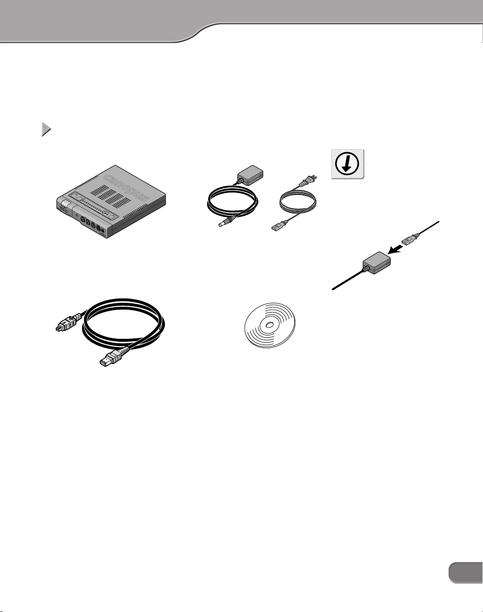
The product package includes the following accessories.
Items included in ADVC-300 packageItems included in ADVC-300 package
Items included in ADVC-300 package
Items included in ADVC-300 packageItems included in ADVC-300 package
• ADVC-300 • AC adapter and cable
• DV cable (6-pin to 4-pin) • CD-ROM
age Contentsage Contents
age Contents
age Contentsage Contents
* The shape of the plug may dif-
fer depending on your point of
parchase.
Tip
As the AC ad apter co mes in a
form that the adapter unit and
cable (to r eceptacle) are s eparated each other, connect them
before using it.
• AD VC-30 0 User Manua l
(this document)
* This programs can be used only
when you agree to the contents
of Software End User License
Agreement displayed at installation. Be sure to confirm the
contens of End User License
Agreement.
13
Page 14
Names and functions of componentsNames and functions of components
Names and functions of components
Names and functions of componentsNames and functions of components
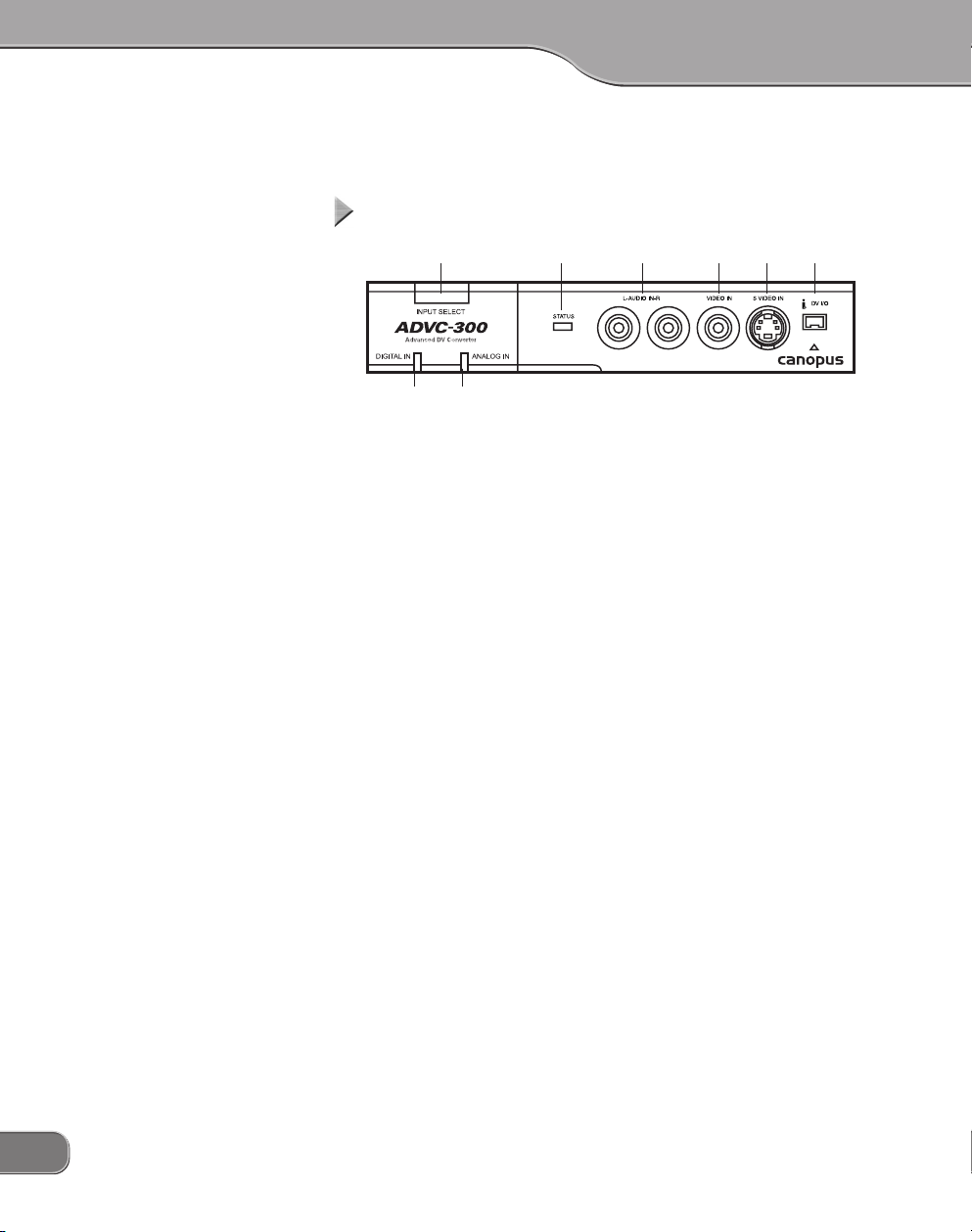
FrontFront
Front
FrontFront
(4)(1) (5) (6) (7) (8)
(3)(2)
(1) [INPUT SELET] switch
This switch sets the input mode to either of DV or analog. The
switch toggles between the following two modes:
• Analog > DV > Analog
* If the [INPUT SELECT] switch is held down for about 3 seconds, color
bars are output. Pressing the switch once again returns you to the DV
input mode.
(2) [DIGITAL IN] LED
Lights while the ADCV-300 is receiving signals from the DV terminal and converting them to analog signals.
(3) [ANALOG IN] LED
Lights while the ADVC-300 is receiving signals from the analog
terminal and converting them to DV signals.
14
(4) STATUS LED
Lights in red when the Macrovision signal or any anomaly has
been detected.
When the standby feature has been enabled, this LED lights in
green if the ADVC-300 enters the standby mode.
(5) AUDIO IN L/R
Terminal for analog audio input.
(6) VIDEO IN
Terminal for composite video input.
(7) S-VIDEO IN
Terminal for S-video input.
(8) DV IN/OUT
Terminal for DV connection (4-pin). Connect this terminal to a DV
device or computer.
Page 15
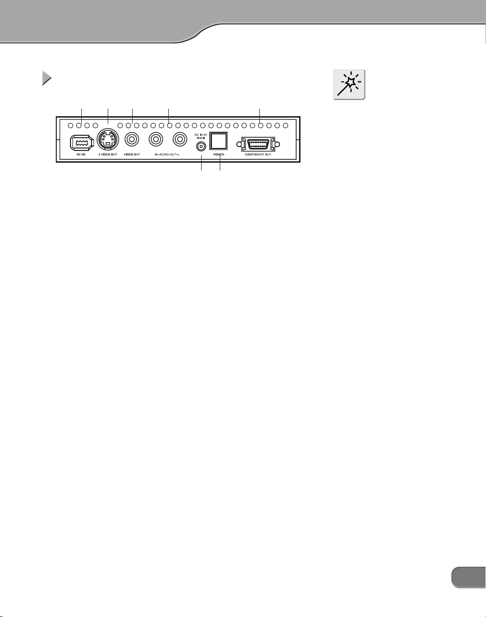
RearRear
Rear
RearRear
(1) (2) (3) (4) (7)
(6)(5)
(1) DV IN/OUT
Terminal for DV connection (6-pin). Connect this terminal to a DV
device or computer.
(2) S-VIDEO OUT
Terminal for S-video output.
(3) VIDEO OUT
Terminal for composite video output.
(4) AUDIO OUT L/R
Terminal for analog audio output.
(5) DC IN 5V
Connect the AC adapter that comes with the product to this terminal.
NOTE
Pl e a s e d o n o t c o nn e c t D V
camcorders to DV connectors on
both sides at the same time. This
operation is not supported.
(6) [POWER] switch
Allows you to turn ON/OFF the ADVC-300.
(7) COMPONENT OUT
Terminal for D1 output.
15
Page 16
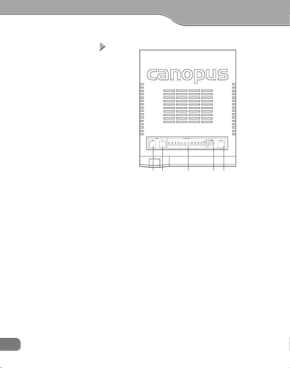
TT
opop
T
op
TT
opop
(3) (4) (5)(1) (2)
(1) [ADJUST DOWN] switch
When selecting an item to set up, pressing this switch moves the
ADJUST LEVEL LED's current indication to the left by one. When
adjusting the quality of image or sound, pressing this switch decreases the setting value by one.
16
(2) [ADJUST UP] switch
When selecting an item to set up, pressing this switch moves the
ADJUST LEVEL LED's current indication to the right by one. When
adjusting the quality of image and sound, pressing this switch
increases the setting value by one.
(3) ADJUST LEVEL LED
Shows the value for the image quality setting or sound quality
setting, etc.
(4) 3D Processing LED
Y/C LED
Lights when 3D Y/C separation is activated for processing analog composite inputs.
* Since S-video inputs come with the luminance (Y) and chrominance
(C) signals separated each other from the start, Y/C separation is not
applied to them and thus this LED does not light.
NR LED
Lights when 3D noise reduction is activated.
Page 17
(5) [ENTER] switch
Use this switch to acknowledge the setting you made.
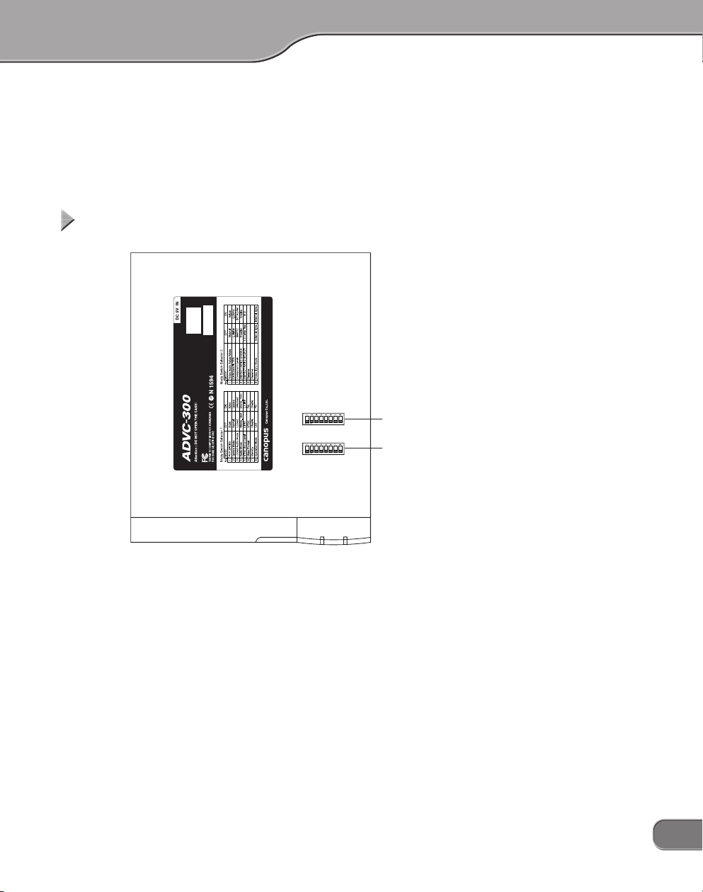
BottomBottom
Bottom
BottomBottom
(2)
(1)
(1) [SW1] DIP switches
DIP switches for setting VIDEO and AUDIO modes.
(2) [SW2] DIP switches
DIP switches for making video settings.
17
Page 18

NOTE
Before changing the DIP switch
se tti ngs , be sure to t urn the
power OFF.
Setting up ADVC-300Setting up ADVC-300
Setting up ADVC-300
Setting up ADVC-300Setting up ADVC-300
[SW1 ] DIP switches[SW1] DIP switches
[SW1 ] DIP switches
[SW1 ] DIP switches[SW1] DIP switches
Allow you to set various modes. No.5, No.6 may differ depending on
your point of parchase.
No.1 PHY Speed setting
Allows you to set the PHY Speed. (Usually, set to S400.)
OFF: S400 ON: S200
No.2 Update Mode setting
Allows you to set Update Mode. (Usually, set it to Normal.)
OFF: Normal ON: Update
18
No.3 Locked Audio Mode setting
Allows you to select whether to use the Locked Audio mode or not.
(Refer to P. 49.)
OFF: Locked ON: Unlocked
No.4 Audio Mode setting
Allows you to select audio frequency.
OFF: 48kHz/16bit ON: 32kHz/12bit
No.5 NTSC Setup Level setting
Allows you to set the black (setup) level. This switch is effective
only in the NTSC format.
OFF: 0 IRE ON: 7.5 IRE (North America, South Korea)
No.6 Video Format setting
Allows you to select video signal format.
OFF: NTSC ON: PAL
When both of No.5 NTSC Setup Level and No.6 Video Format are set
to ON, the SECAM format is used.
* At this time, the SECAM format is used for input and PAL format for
output.
Page 19

No.7 Standby setting
Allows you to set whether to use the standby feature (which detects
the signal coming from devices connected to the DV terminal).
OFF: Disable ON: Enable
* Standby feature
This feature turns ON/OFF the ADVC-300 power automatically after detecting ON/OFF of the power of the device connected to the
DV terminal.
You can use the [POWER] switch to turn ON/OFF the ADVC-300
power as usual even when the standby feature is active.
No.8 Operation Mode setting
Allows you to select the control method of ADVC-300.
OFF: UNIT ON: PC
* UNIT mode
In this mode, the ADVC-300 operates standalone, thus all the operations are made via the buttons and indicators on it. To set the
operation mode, use the DIP switch for it. You can set up the quality of image and sound on the ADVC-300. This mode is provided
for using the ADVC-300 as a simple DV converter.
* PC mode
In this mode, the ADVC-300 is controlled by a computer connected
to it via the IEEE 1394 interface. Image and sound quality is controlled from the computer. The buttons on the ADVC-300 are not
operable in this mode.
NOTE
When you use the standby feature, use either of the DV terminal on the front or the one on the
rear, not both, for connecting your
device.
* Depending on the specification
of your device’s (computer’s)
DV terminal standby function
or the OHCI card specification,
the st andby mo de may not
work.
Tip
Operation Mode
The PC mode and UNIT mode are
available for your selection.
When ch an gi ng the mo de , be
sure to turn OFF the ADVC-300
powe r bef or e set ting the DIP
switch.
19
Page 20

Tip
Th e fol l o wing fun c t ions are
changeable under the PC mode.
The set values are saved in the
ADVC-300's memory.
• Locked Audio Mode
([SW1] DIP switch No. 3)
• Audio Mode
([SW1] DIP switch No. 4)
The following functions are not
changeable from the PC.
• NTSC Setup Level
([SW1] DIP switch No. 5)
• Video Format
([SW1] DIP switch No. 6)
• Chroma Filter
([SW2] DIP switch No. 2)
• Component Level
([SW2] DIP switch No. 3)
• Aspect Ratio Enable
([SW2] DIP switch No. 4)
• Aspect Ratio Select
([SW2] DIP switch No. 5)
• Video Sync Mode
([SW2] DIP switch No. 8)
[SW2 ] DIP switches[SW2] DIP switches
[SW2 ] DIP switches
[SW2 ] DIP switches[SW2] DIP switches
Allows you to make video and audio settings.
All the switches have been set to OFF at the time of shipment.
No.1 Video Audio Adjust Mode setting
Allows you to enable the adjustment on image and sound quality.
Usually, set this to [OFF: Normal] (Refer to P. 22).
OFF: Normal ON: Adjust
No.2 Chroma Filter Setting
Allows you to select the Chroma filter.
OFF: 1.3 MHz ON: 2.0 MHz
No.3 Component Level setting
Allows you to select the component level from SMPTE and BETACAM.
OFF: SMPTE ON: BETACAM
20
No.4 Aspect Ratio Enable setting
Allows you to enable the aspect ratio setting (No.5 Aspect Ratio
Select). If set to [OFF: Disable], the aspect ratio of “4:3” is used for
D1 output.
OFF: Disable ON: Enable
No.5 Aspect Ratio Select setting
Allows you to select the aspect ratio for D1 output.
OFF: 4:3 LetterBox ON: 16:9
No.6 Reserved
Not used (Usually, set it to [OFF].)
No.7 Reserved
Not used (Usually, set it to [OFF].)
Page 21

No.8 Video Sync Mode setting
Allows you to select whether to enable the PLL (phase-locked loop)
control or not. This switch is effective only for DV inputs.
OFF: External Sync ON: Internal Sync
If set to [OFF: External Sync], the ADVC-300 synchronize the frame
and subcarrier period of analog video to be output with the pulses of
the incoming DV stream. If set to [ON: Internal Sync], the ADVC-300
uses its internal circuit to determine the frame period of the analog
video to be output.
21
Page 22

Tip
• The image a nd sound quality
adjustments for external inputs
is commonly applied to both of
S-video and composite inputs.
• You cannot adjust DV input devices using this feature.
• The setti ngs s pecifie d in the
image quality adjustment are applied when analog data is converted to DV data.
Adju s ting imag e and sound qual ityAdju s ting imag e and sound qual ity
Adju s ting imag e and sound qual ity
Adju s ting imag e and sound qual ityAdju s ting imag e and sound qual ity
ADVC-300 is equipped with the image and sound quality adjustment
feature. You can save one setting for external (LINE) inputs.
1
1
2
2
Set the ADVC-300 [POWER] switch to [OFF].
Set the [SW2] DIP switch No. 1 to [ON].
> The Video Audio Adjust Mode will be set to [Adjust].
22
3
3
Set the [POWER] switch to [ON].
> The [ADJUST LEVEL] LEDs will light in series in the di-
rection from [-5] to [PAGE1/2] twice. After that, LED [-5]
will blink.
> [3D Processing] LEDs, [Y/C] and [NR] turn off.
> The ADVC-300 will enter the image and sound quality
adjustment mode and be put to the standby state.
Page 23

4
4
Select your desired item to adjust by pressing the
[ADJUST UP] or [ADJUST DOWN] switch.
LED Desired item Note
PAGE1[
-
5] Image and sound
PAGE1[-4] Brightness 256 levels
-
PAGE1[
PAGE1[
PAGE1[
PAGE1[ 0] Sharpness 256 levels
PAGE1[+1] Volume 256 levels
PAGE1[+2] Low tone 31 levels
PAGE1[+3] High tone 31 levels
PAGE1[+4] Image
PAGE1[+5] Sound
PAGE1[-5] Y/C separation setting 4 options
PAGE1[
3] Contrast 256 levels
-
2] Hue 256 levels
-
1] Saturation 256 levels
-
4] Audio AGC setting 5 levels
Default setting
Default setting
Default setting
Tip
To c h ange t h e pag e , s elect
[PAGE1/2], an d then pres s the
[ENTE R] switch. If the page is
switched to page 2, the [PAGE1/
2] LED lights up.
23
Page 24

5
5
Press the [ENTER] switch to select the currently chosen item
> The [ADJUST LEVEL] LEDs will light in series from [-5] to
[PAGE1/2] twice, and then the current setting value (previously saved value) will be indicated.
> PAGE1[-5]: When the image and sound default set-
ting has been selected:
All the LEDs of [ADJUST LEVEL] and [3D
Processing] will blink at the same time. Proceed to step 7.
> PAGE1[+4]: When the image default setting has been
selected:
All the LEDs of [ADJUST LEVEL] will blink
at the same time. Proceed to step 7.
> PAGE1[+5]: When the sound default setting has been
selected:
The two LEDs of [3D Processing] will blink
at the same time. Proceed to step 7.
24
Page 25

6
6
Setting items
Brightness Low < Default 128 < High
Contrast Low < Default 128 < High
Hue Green < Default 128 < Red
Saturation Light < Default 128 < Deep
Sharpness Weak < Default 128 < Strong
Volume Low < Default 237 < High
Setting items
Low tone Weak < Default 0 < Strong
High tone Weak < Default 0 < Strong
Setting items
Y/C separation setting
Audio AGC setting AGC Level
Adjust the setting value by pressing the [ADJUST UP]
or [ADJUST DOWN] switches.
-
50~-
4
-
3
-
2
-
LED
Settable
values
LED-5-4-3-2-1 0 1 2 3 4 5
Settable
values
LED
Y/C
NR
AGC Level
24~
47~
-
15~-14~-9~-6~-3~ 0 1~ 4~ 7~ 10~
-
5
-4-3-2-
OFF
2D
OFF OFF
OFF
3D 3D
3D
2
1
1
70~
93~0116~1140~2163~3186~4209~
1
3D
34
Tip
You can increase or decrease the
val ue continuously by holdi ng
down the [ADJUST UP] or [ADJUST DOWN] key.
5
232~255
Tip
If the value for the volume setting has been set high, the sound
may b e dis t o r t e d wh e n the
ADVC-30 0 proc esses a n inpu t
source with a high volume level.
13~15
7
7
Press the [ENTER] switch to set to the current choice.
Tip
Repeat steps 4 to 7 if you want to
set up another item.
> The setting will be updated.
> The [ADJUST LEVEL] LEDs will light in series from [-5] to
[PAGE1/2] twice, and then [-5] LED will blink.
25
Page 26

8
8
Set the ADVC-300 [POWER] switch to [OFF].
9
9
Set the [SW2] DIP switch No. 1 to [OFF].
> The Video Audio Adjust Mode will be set to [Normal].
> This completes the setup procedure.
26
Page 27

Installing Picture Controller 300Installing Picture Controller 300
Installing Picture Controller 300
Installing Picture Controller 300Installing Picture Controller 300
System requirementsSystem requirements
System requirements
System requirementsSystem requirements
Canopus does not gurantee all system meeting the below requirements to work accordingly with the ADVC-300.
Computer
The following are the minimum requirements for using this product.
Windows
• CPU: Pentium III or faster
• Memory: 128 MB or more
• CD-ROM drive: Required to set up the software.
• HDD: 4 MB or more of available space for installing the
software
• To use Picture Controller 300, an OHCI (IEEE1394) interface is re-
quired.
Macintosh
• CPU: G3 or faster
• Memory: 128 MB or more
• CD-ROM drive: Required to set up the software.
• HDD: 4 MB or more of available space for installing the
software
• Your Mac needs a standard FireWire port to use Picture Controller
300.
Supported OS
Windows
• Windows 2000 Professional + SP4
• Windows XP Home/Professional Edition + SP1
*DirectX 8 or later is required.
Macintosh
• Mac OS X 10.2.7 or later
27
Page 28

Installat i o n (for Window s )Installat i o n (for Window s )
Installat i o n (for Window s )
Installat i o n (for Window s )Installat i o n (for Window s )
The following describes the procedure for installing Picture Controller
300 on a computer running Windows XP.
* You can install Picture Controller 300 without ADVC-300 connected with the
computer.
Tip
Do not remo ve the “ADVC -300
Applications CD” from the CDROM drive until the installation
is completed.
1
1
2
2
3
3
Insert the “ADVC-300 Applications CD” into the CDROM drive.
> The CD-ROM automatically starts up and the installation
screen is displayed.
* When the CD-ROM does not automatically start up, run
“ADVC-300 Applications CD” > [PCtrl300] > [Steup.exe].
Click [Next].
When the License Agreement is displayed, carefully
read the content and click [Yes] only if you agree to
them. If you do not agree to the License Agreement,
click [No] to stop installation and notify our customer
support personnel in writing.
* If you do not agree to the License Agreement, you can-
not use this software.
28
Page 29

4
4
Click [Next].
* If you want to change the folder where the program will
be installed into, click [Browse...] and specify your desired folder.
> The installation process starts.
5
5
6
6
Select your desired options and click [Next].
> Be sure to read the readme file since it contains content
not covered in the manuals.
Click [Finish].
Tip
AD V C - 3 0 0 c o me s w i t h t h e
“ProCoder Demo version”. When
you w ant to install “Pro Co de r
Demo”, run “ADVC-300 Applications CD” > [ProCoder Trial] >
[ProCoderDemo_1_25.exe].
> This completes the installation of Picture Controller 300.
29
Page 30

Insta l lation (for Macintosh)Insta l lation (for Macintosh)
Insta l lation (for Macintosh)
Insta l lation (for Macintosh)Insta l lation (for Macintosh)
The following describes the procedure for installing Picture Controller
300 on a computer running Mac OS X.
* You can install Picture Controller 300 without ADVC-300 connected with the
computer.
Tip
Do not remo ve the “ADVC -300
Applications CD” from the CDROM drive until the installation
is completed.
1
1
2
2
Insert the “ADVC-300 Applications CD” into the CDROM drive.
> The [ADVC300] icon will appear.
Run [ADVC300] > [PCtrl300] > [Picture Controller
300.pkg].
30
3
3
> The installer starts up.
Enter your name and password, and then click [OK].
Page 31

4
4
Click [Continue].
5
5
Read the content carefully, and click [Continue].
> Be sure to read the readme file since it contains content
not covered in the manuals.
31
Page 32

6
6
Click [Continue].
> The License Agreement will be displayed.
Read the content carefully and click [Agree] only if
you agree to it.
> If you do not agree to the License Agreement, click [Dis-
agree] to stop installation and notify our customer support personnel in writing.
* If you do not agree to the License Agreement, you can-
not use this software.
32
7
7
Select the destination folder for installation, and then
click [Continue].
Page 33

8
8
Click [Install].
> The installation process starts.
9
9
After the installation completes, click [Close].
> The [Picture Controller 300] folder is created in the [Ap-
plications] folder.
33
Page 34

NOTE
Do not turn ON/OFF the ADVC300 power when the computer
connected to the ADVC-300 via a
DV cable is OFF or in a standby
mode.
Tip
Picture Controll er 300 lets you
adjust the image and sound quality of streams coming from the
com puter via the D V term inal.
These settings are effective even
after the ADVC-300 is turned OFF
or disconnected from the computer.
NOTE
When the ADVC -300 po wer is
OFF, set the [SW1] DIP switch No.
8 to [ON: PC] (PC mode) beforehand (Refer to P.19).
How to use Picture Controller 300How to use Picture Controller 300
How to use Picture Controller 300
How to use Picture Controller 300How to use Picture Controller 300
FF
or Windowsor Windows
F
or Windows
FF
or Windowsor Windows
1
1
Connect the ADVC-300 to the computer, boot up the
computer, and set the [POWER] switch to [ON].
34
Page 35

2
2
Click the [Start] menu, point to [All Programs], and
click [Canopus Picture Controller 300].
> Picture Controller 300 will start up.
Tip
• About Pict ure Controller 300
setup screen (Refer to P. 37 to
45)
[Open Previe w] ([Cl os e Preview]) button
Open s the p re view scr een
(closes the preview screen).
[Default] button
Reverts the setting to the default.
[OK] button
Saves the current setting and
exits Picture Controller 300.
[Cancel] button
Exits Picture Controller 300
without saving the current setting.
35
Page 36

NOTE
When the ADVC -300 po wer is
OFF, set the [SW1] DIP switch No.
8 to [ON: PC] (PC mode) beforehand (Refer to P.19).
FF
or M a c in toshor M a c in tosh
F
or M a c in tosh
FF
or M a c in toshor M a c in tosh
1
1
Connect the ADVC-300 to the computer, boot up the
computer, and set the [POWER] switch to [ON].
Tip
• About Pict ure Controller 300
setup screen (Refer to P. 37 to
45)
[Preview] button
Opens the preview screen.
[Default] button
Reverts the setting to the default.
[Restore] button
Restores the previously saved
setting.
• Picture Controller 3 00 setup
items for Windows and the ones
for Macintosh are identical.
* Scre ens hot s of ta b pag es
shown in this manual are the
ones for Windows.
2
2
Click [Picture Controller 300] in the [Picture Controller 300] folder.
> Picture Controller 300 will start up.
36
Page 37

[Basic] tab[Basic] tab
[Basic] tab
[Basic] tab[Basic] tab
This tab page is provided for adjusting the image and sound quality.
• Image Setting
Allows you to adjust the brightness, contrast, saturation, hue, and
sharpness of your video.
• Audio Setting
Allows you to adjust the volume, high and low tones and AGC gain
of video.
Tip
Audio Setting: AGC gain
The sound volume is automatically adjusted by this feature. You
can set the level of AGC automatic
adjustment.
37
Page 38

NOTE
Wh en the S-v ide o i npu t, Y/C
separation of the [Filter] tab can
not set.
[Filter] tab[Filter] tab
[Filter] tab
[Filter] tab[Filter] tab
This tab page is provided for setting up Y/C separation and DNR.
38
• Video Processing
[Y/C Separation 2D]
When displaying composite video, the ADVC-300 separates the
luminance (Y) and chrominance (C) signals based on the scanning lines above and below.
[Y/C Separation 3D]
When displaying composite video, the ADVC-300 compares the
current frame with the previous one using the Motion Detection
circuit and separates Y/C signals in the areas determined to be
still images. In this mode, Y/C signals are separated more effectively than in the 2D mode.
Page 39

• 3D Noise Reduction
Removes noise from each of the luminance (Y) and chrominance
(C) signals after comparing the current frame with the previous one.
[Y Signal]
Allows you to set the noise reduction level for the luminance (Y)
signal.
[C Signal]
Allows you to set the noise reduction level for the chrominance
(C) signal.
• 2D Noise Reduction
Removes noise by blurring the entire image uniformly by using the
built-in filter.
[Y Signal]
Allows you to set the noise reduction level for the luminance (Y)
signal.
[C Signal]
Allows you to set the noise reduction level for the chrominance
(C) signal.
• 3D Y/C Separation
[Motion Detection]
Allows you to adjust the sensitivity of the Motion Detection circuit when [Y/C Separation 3D] has been selected.
Tip
Digital 3D Y/C separation
The composite signal is a mix of the luminance (Y) and chrominance (C) signals. To compress the composite signal
to the DV format, the luminance (Y) and
chrominance (C) signals needs to be
separated each other. For doing this
separation, two methods are available.
• 2D Y/C separation
In this method, Y/C signals are separated using the vertical relationship of
a dot. Although this method produces
color noise when a dot has little relationship with the upper and lower dots
such as the case of a slanted white line
on the black background, it is widely
accepted recent years because this
method can work with a higher resolution screen.
• 3D Y/C separation
In this method, Y/C signals are separated based on the time relationship
of dots displayed at the same spot. This
method enables you to obtain the
highest quality of image among the
available methods today. In this
method, still pictures, which have
strong relationship in the time axis, are
processed using the time axis, and motion pictures, which have weak relationship in the time axis, are processed
using the relationship with the scanning lines above and below (2 dimensions.). This method requires a digital
frame buffer and motion detection
mechanism.
Digital 3D Noise Reduction
In a conventional method, noise is reduced by lowering the frequency characteristics for the entire picture (blurring)
in one or two-dimensions. This method
has a problem in affecting other parts
not containing noise. The digital 3D
noise reduction feature employed by
ADVC-300, however, removes noise
after detecting noise using the characteristic of noise (noise has little relation
to others in the time axis), the advert
effect to the image is kept minimal.
* Because of the construction, it is not a
universal solution for all noises.
39
Page 40

[Video1] tab[Video1] tab
[Video1] tab
[Video1] tab[Video1] tab
This tab page is provided to set the correction for color graduation. If
this correction is enabled for a video having black or white crushes, the
video is adjusted and become clear and crisp.
40
Tip
We recom mend setting th is to
[Middle] or [Strong] because you
may not recognize the effect of
this setting if it has been set to
[Weak].
NOTE
If the cursor is set to the far right
when [Adjustment] has been set
to [Weak] or [Middle], the screen
image may become whitish because of insufficient correction.
• Black Expansion
Corrects grayish black by correcting the gain of black (low brightness) areas and thereby enhancing their blackness.
[Adjustment]
Allows you to set the level of black expansion. The higher the
value, the deeper the black will be.
[Base Level]
Allows you to specify up to which level of brightness you want to
enhance the black. The more the cursor is moved to the right, the
higher (brighter) the bright level will be.
[Auto Adjust]
Adjusts the level of black expansion based on the average brightness of the incoming video.
Page 41

• White Peak Adjust
Corrects a whiteout image by correcting the gain of white (high
brightness) areas and thus restoring the contrast in them.
[Adjustment]
Allows you to set the level of white peak adjustment. The higher
the level, the lower the white peak will be.
[Base Level]
Allows you to specify up to which level of brightness you want to
correct the white peak. The more the cursor is moved to the left,
the lower (darker) the bright level will be.
[Auto Adjust]
Adjusts the level of white peak based on the average brightness
of the incoming video.
• White Step
Lowers the luminance signal level when the incoming video has a
higher level of the average brightness to enhance the reproducibility of graduation in brighter areas.
[Base Level]
Allows you to specify up to which level of brightness you want to
lower the luminance signal as correction. The more the cursor is
moved to the left, the lower (darker) the bright level will be.
[Adjustment]
Adjusts the level of white graduation correction based on the
average brightness of the incoming video.
Tip
This feature is effective for images with white spreading over
the screen.
41
Page 42

[Video2] tab[Video2] tab
[Video2] tab
[Video2] tab[Video2] tab
This tab page is provided to sets up the edge correction and AGC.
42
• Edge Adjustment
Corrects the edge of human or object profiles in videos.
[Horizontal Edge]
Corrects horizontal edges in video. Vertical edges are thus enhanced.
[Vertical Edge]
Corrects vertical edges in video. Horizontal edges are thus enhanced.
Page 43

• Video AGC
Sets up the AGC feature for video in detail. Checkmark this option if
you want to automatically set the brightness of the entire video to
an optimal level.
[AGC]
If [Auto] is checkmarked, the brightness of the entire video will
be automatically adjusted. When [Fix] is checkmarked, the brightness of the entire video will be adjusted using the fixed value.
[Set Auto Gain]
Allows you to set the automatic adjustment level of AGC if [AGC]
has been set to [Auto]. The more the cursor is moved to the right,
the higher the level for AGC will be, thereby making the video
less bright.
[Y Adjust]
Allows you to set the fixed brightness level of AGC if [AGC] has
been set to [Fix], The more the cursor is moved to the right, the
more (brighter) the gain will be.
Tip
AGC is an acronym of “Auto Gain
Control” and the function to automatically adjust the image graduation and such. Using this feature,
you can always display the video
in an op timal b rightness level
even if the video input to display
change every time.
43
Page 44

[Audio] tab[Audio] tab
[Audio] tab
[Audio] tab[Audio] tab
Sets the sampling rate and the Locked Audio mode.
44
NOTE
This switch is effective only for
analog inputs.
Tip
This setting cannot be altered in
the UNIT mode.
• Audio Encode
[Locked audio mode]
Allows you to select whether to use the Locked Audio mode or
not.
[Sampling Rate]
Allows you to select an audio frequency.
[48kHz 16bit]
Audio data will be processed as 16-bit stereo sound at 48 kHz.
Select this option when you want to create DVD videos.
[32kHz 12bit]
Audio data will be processed as 4-channel 12-bit data at 32 kHz.
ADVC-300 processes only the main 2 channels and no sound is
recorded in the 2 sub-channels.
Page 45

[V[V
ersion Info] tabersion Info] tab
[V
ersion Info] tab
[V[V
ersion Info] tabersion Info] tab
This tab page shows the version information of Picture Controller 300.
45
Page 46

NOTE
Computer DV camera
Receptacle
*When both of the video and
S-video terminals are used,
the S-video terminal takes priority.
Audio
output
VCR DVD drive
Input
Input
Input
TV monitor
Video
output
S video
output
Connect either
of the cables.
AC adapter
Output
Output
Front
4pin 6pin
6pin
DV
ADVC-300
DV
4pin
Rear
Before connecting/disconnecting
a DV cable, be sure to turn OFF
the power of your computer and
ADVC-300.
Connecting ADVC-300Connecting ADVC-300
Connecting ADVC-300
Connecting ADVC-300Connecting ADVC-300
Analo g video inputAnalo g video input
Analo g video input
Analo g video inputAnalo g video input
Make connections between devices as shown in the figure.
46
Page 47

Capturing analog video into computerCapturing analog video into computer
Capturing analog video into computer
Capturing analog video into computerCapturing analog video into computer
1
1
2
2
Press the [POWER] switch on the rear.
By pressing the [INPUT SELECT] switch on the front,
switch the input mode to the ANALOG IN external
input mode.
> The ANALOG IN LED will light.
NOTE
Do not turn ON/OFF the ADVC300 power when the computer
connected to the ADVC-300 via a
DV cable is OFF or in the standby
mode. Otherwise, your computer
may become unbootable depending on the OHCI card being used.
In this instance, disconnect the
ADVC-300 fr om the co mp ut er
temporarily, turn OFF and ON the
power of the computer, and then
conn ec t the A DV C-300 to the
computer again.
3
3
4
4
1
1
2
2
3
3
Playback the video you want to capture on the analog VCR.
Capture the video on your computer.
> For how to capture the video on your computer, consult
the user's manual of the software you are using.
Recording analog video to DV cameraRecording analog video to DV camera
Recording analog video to DV camera
Recording analog video to DV cameraRecording analog video to DV camera
Press the [POWER] switch on the rear.
By pressing the [INPUT SELECT] switch on the front,
switch the input mode to the ANALOG IN external
input mode.
> The ANALOG IN LED will start light.
Put the DV camera in the record pause mode.
Tip
Audio sampling frequency during
capturing
In Line input selection: You can
select from 48 kHz (16-bit) and
32 kHz (12-bit). Select this setting using the DIP switch or “Picture Controller 300”.
4
4
5
5
Playback the video you want to copy on the analog
VCR.
Release the pause button of the DV camera.
> The analog video will be copied to the DV camera.
47
Page 48

NOTE
Computer DV camera
Receptacle
Audio
input
Video
input
S video
input
Connect either of
the cables.
VCR TV monitor
D terminal
input
Component
video input
Input
Output
Output
Output
Output
Output
Input
Front Rear
DV
6pin
4pin 6pin
ADVC-300
4pin
DV
AC adapter
Before connecting/disconnecting
a DV cable, be sure to turn OFF
the power of your computer and
ADVC-300.
NOTE
Do not turn ON/OFF the ADVC300 power when the computer
connected to the ADVC-300 via a
DV cable is OFF or in the standby
mode. Otherwise, your computer
may become unbootable depending on the OHCI card being used.
Digi tal video inputDigi tal video input
Digi tal video input
Digi tal video inputDigi tal video input
Make connections between devices as shown in the figure.
48
Page 49

WW
atching digital video o n TV monitoratching digital video o n TV monitor
W
atching digital video o n TV monitor
WW
atching digital video o n TV monitoratching digital video o n TV monitor
1
1
2
2
3
3
1
1
2
2
Press the [POWER] switch on the rear.
By pressing the [INPUT SELECT] switch, switch the
input mode to DIGITAL IN.
> The DIGITAL IN LED will light.
Output your desired digital video from the computer
(or DV camera).
> The digital video will be displayed on the TV monitor.
* For how to output digital video on your computer, con-
sult the user’s manual of the software you are using.
Recording digital video to analog VCRRecording digital video to analog VCR
Recording digital video to analog VCR
Recording digital video to analog VCRRecording digital video to analog VCR
Press the [POWER] switch on the rear.
By pressing the [INPUT SELECT] switch, switch the
input mode to DIGITAL IN.
> The DIGITAL IN LED will light.
3
3
4
4
5
5
Put the analog VCR in the record pause mode.
Playback the video you want to copy on the DV camera.
Release the pause button of the analog VCR.
> The digital video is recorded to the analog VCR.
49
Page 50

TT
echnical Informationechnical Information
T
echnical Information
TT
echnical Informationechnical Information
Prio rities am ong analo g input signalsPrioritie s among analog input signals
Prio rities am ong analo g input signals
Prio rities am ong analo g input signalsPrioritie s among analog input signals
When all the connectors are used at the same time, priority is given in
the order shown below:
• Video
1. S-video input
2. Composite input
Audio modesAudio modes
Audio modes
Audio modesAudio modes
48kHz/16-bit mode
In this mode, audio data is recorded as 16-bit stereo sound at 48 kHz.
Select this option when you create DVD videos.
32kHz/12-bit mode
In this mode, 4 channels of 12-bit audio signals are recorded at 32kHz.
When ADVC-300 is used for recording, audio data is recorded in only
the 2 main channels and no sound is recorded in the 2 sub-channels.
Unlocked mode
Unlocked audio in consumer products are allowed to have some
deviation in the number of audio samples per one video frame. If this
deviation is accumulated along with elapsed time, however, it results in sound drift. On the other hand, the Locked Audio mode ensures synchronization between audio and video by restricting the
number of audio samples per one video frame in accordance with a
preset pattern, thereby sound drift does not take place. When the
Locked Audio mode is used for capturing from a video source with
highly irregular signals such as game machines, however, the recorded sound may contain noises because incoming signals exceed
the limit for regulating the number of audio samples in accordance
with the locked audio pattern. For that reason, we made the Unlocked mode available for your use.
50
Copyright protection featureCopyright protection feature
Copyright protection feature
Copyright protection featureCopyright protection feature
This product supports copyright protection technologies such as copyprevention technology. If the ADVC-300 receives data with copy-prevention signals attached, it outputs the data with extremely low brightness and contrast. The STATUS LED will light to indicate this.
Page 51

SpecificationsSpecifications
Specifications
SpecificationsSpecifications
Video signal formats NTSC(0IRE), NTSC(7.5IRE), SECAM*, PAL
DV 4-pin iLINK ConnectorFront terminals
6-pin iLINK ConnectorRear terminals
Analog Video S-Video(MiniDIN 4 Pin)x1
Analog Audio 48kHz 16bit 2ch
Component video D connector (D1) x 1Rear terminal Output
Power supply AC adapter
Power consumption Max. 9W
Ambient temperature 0 to 45oC
External dimensions (excluding protrusions) 146 (W) x 27.2 (H) x 175 (D)
Weight 430g
* When the SECAM format is used, the SECAM format is used just for inputs, and PAL is used for analog video
outputs.
Front terminal Input
Rear terminal Output
Data
RCA jack Compositex1
S-Video(MiniDIN 4 Pin)x1
RCA jack Compositex1
32kHz 12bit 4ch
(ADVC-300 processes only the main 2 channels
and not other 2 sub-channels.)
RCA jack x2(L/R)Front terminal Input
RCA jack x2(L/R)Rear terminal Output
0.5W in the standby mode
51
Page 52

TT
roubleshootingroubleshooting
T
roubleshooting
TT
roubleshootingroubleshooting
If you have found any troubles, check the following points before contacting us for repair.
Symptoms Cause/Action
Pressing the POWER
switch does turn ON
the ADVC-300 power.
> Check that the AC adapter is connected to
the DC IN 5V connector and the receptacle.
Video and audio are
not output.
It cannot record. > If the video input or audio data contains
Color bars are not displayed.
Th e bu ttons on the
ADVC-300 are not operable.
> Check if the POWER switch is ON. Check
that this product and DV/analog devices
are properly connected.
copyright protection signals, it cannot be
recorded properly.
> The [INPUT SELECT] switch needs to be
pressed for 3 seconds or more without a
break.
> The mode selection [SW1] DIP switch No
.8 is set to ON. In this mode, the ADVC300 is operable only from the computer.
52
Page 53

53
Page 54

54
F157311042
 Loading...