

Canon WS8400, W8400 Series, W8400PG Service Manual

Service Manual
W8400 Series
W8400
Apr 5 2005


Application
This manual has been issued by Canon Inc. for qualified persons to learn technical theory, installation, maintenance, and repair
of products. This manual covers all localities where the products are sold. For this reason, there may be information in this
manual that does not apply to your locality.
Corrections
This manual may contain technical inaccuracies or typographical errors due to improvements or changes in products. When
changes occur in applicable products or in the contents of this manual, Canon will release technical information as the need
arises. In the event of major changes in the contents of this manual over a long or short period, Canon will issue a new edition
of this manual.
The following paragraph does not apply to any countries where such provisions are inconsistent with local law.
Trademarks
The product names and company names used in this manual are the registered trademarks of the individual companies.
Copyright
This manual is copyrighted with all rights reserved. Under the copyright laws, this manual may not be copied, reproduced or
translated into another language, in whole or in part, without the written consent of Canon Inc.
COPYRIGHT © 2001 CANON INC.
Printed in Japan
Caution
Use of this manual should be strictly supervised to avoid disclosure of confidential information.
Symbols Used
This documentation uses the following symbols to indicate special information:
Symbol Description
Indicates an item of a non-specific nature, possibly classified as Note, Caution, or Warning.
Indicates an item requiring care to avoid electric shocks.
Indicates an item requiring care to avoid combustion (fire).
Indicates an item prohibiting disassembly to avoid electric shocks or problems.
Indicates an item requiring disconnection of the power plug from the electric outlet.
Indicates an item intended to provide notes assisting the understanding of the topic in question.
Memo
Introduction
REF.
Indicates an item of reference assisting the understanding of the topic in question.
Provides a description of a service mode.
Provides a description of the nature of an error indication.

Introduction
The following rules apply throughout this Service Manual:
1. Each chapter contains sections explaining the purpose of specific functions and the relationship between electrical and mechanical systems with
reference to the timing of operation.
In the diagrams, represents the path of mechanical drive; where a signal name accompanies the symbol , the arrow indicates the
direction of the electric signal.
The expression "turn on the power" means flipping on the power switch, closing the front door, and closing the delivery unit door, which results in
supplying the machine with power.
2. In the digital circuits, '1'is used to indicate that the voltage level of a given signal is "High", while '0' is used to indicate "Low".(The voltage value,
however, differs from circuit to circuit.) In addition, the asterisk (*) as in "DRMD*" indicates that the DRMD signal goes on when '0'.
In practically all cases, the internal mechanisms of a microprocessor cannot be checked in the field. Therefore, the operations of the microprocessors
used in the machines are not discussed: they are explained in terms of from sensors to the input of the DC controller PCB and from the output of the
DC controller PCB to the loads.
The descriptions in this Service Manual are subject to change without notice for product improvement or other purposes, and major changes will be
communicated in the form of Service Information bulletins.
All service persons are expected to have a good understanding of the contents of this Service Manual and all relevant Service Information bulletins and be
able to identify and isolate faults in the machine."


Contents
Contents
Chapter 1 PRODUCT DESCRIPTION
1.1 Product Overview ....................................................................................................................................... 1- 1
1.1.1 Product Overview ....................................................................................................................................................1- 1
1.2 Features ..................................................................................................................................................... 1- 3
1.2.1 Features ..................................................................................................................................................................1- 3
1.2.2 Printhead .................................................................................................................................................................1- 3
1.2.3 Ink Tank...................................................................................................................................................................1- 3
1.2.4 Cutter Unit ...............................................................................................................................................................1- 3
1.2.5 Roll Holder............................................................................................................................................................... 1- 4
1.2.6 Consumables...........................................................................................................................................................1- 4
1.3 Product Specifications ................................................................................................................................1- 6
1.3.1 General Specifications.............................................................................................................................................1- 6
1.4 Detailed Specification .................................................................................................................................1- 8
1.4.1 Type of media.........................................................................................................................................................1- 8
1.4.2 Printing Speed and Direction...................................................................................................................................1- 8
1.4.3 Interface Specifications ...........................................................................................................................................1- 9
1.5 Names and Functions of Components ..................................................................................................... 1- 11
1.5.1 Front ......................................................................................................................................................................1- 11
1.5.2 Rear.......................................................................................................................................................................1- 12
1.5.3 Carriage.................................................................................................................................................................1- 13
1.5.4 Internal part ...........................................................................................................................................................1- 13
1.6 Basic Operation ........................................................................................................................................ 1- 15
1.6.1 Operation Panel.....................................................................................................................................................1- 15
1.6.2 Change of Printer Status .......................................................................................................................................1- 16
1.6.3 Main Menu............................................................................................................................................................. 1- 16
1.7 Safety and Precautions ............................................................................................................................1- 23
1.7.1 Safety Precautions ................................................................................................................................................1- 23
1.7.1.1 Moving Parts .......................................................................................................................................................................... 1- 23
1.7.1.2 Ink .......................................................................................................................................................................................... 1- 23
1.7.1.3 Electrical Parts ....................................................................................................................................................................... 1- 25
1.7.2 Other Precautions..................................................................................................................................................1- 26
1.7.2.1 Printhead................................................................................................................................................................................ 1- 26
1.7.2.2 Ink Tank ................................................................................................................................................................................. 1- 27
1.7.2.3 Handling the Printer ............................................................................................................................................................... 1- 28
1.7.3 Precautions When Servicing Printer......................................................................................................................1- 29
1.7.3.1 Stored Data ............................................................................................................................................................................ 1- 29
1.7.3.2 Firmware Confirmation........................................................................................................................................................... 1- 30
1.7.3.3 Precautions Against Static Electricity..................................................................................................................................... 1- 30
1.7.3.4 Precautions for Disassembly/Reassembly............................................................................................................................. 1- 30
1.7.3.5 Self-Diagnostic Feature ......................................................................................................................................................... 1- 30
1.7.3.6 Disposing of Lithium Battery .................................................................................................................................................. 1- 30
Chapter 2 TECHNICAL REFERENCE
2.1 Basic Operation Outline..............................................................................................................................2- 1
2.1.1 Printer Block Diagram..............................................................................................................................................2- 1
2.1.2 Print Signal Sequence .............................................................................................................................................2- 1
2.1.3 Print Driving .............................................................................................................................................................2- 3
2.2 Firmware..................................................................................................................................................... 2- 5
2.2.1 Power On/Off........................................................................................................................................................... 2- 5
2.2.2 Power Off................................................................................................................................................................. 2- 5

Contents
2.2.3 Print Control.............................................................................................................................................................2- 6
2.2.4 Print position adjustment..........................................................................................................................................2- 7
2.2.5 Head Management ..................................................................................................................................................2- 8
2.2.6 Overheating Protection Control of Printhead ...........................................................................................................2- 8
2.2.7 Pause between Pages.............................................................................................................................................2- 8
2.2.8 White Raster Skip ....................................................................................................................................................2- 8
2.2.9 Sleep Mode..............................................................................................................................................................2- 8
2.3 Printer Mechanical System......................................................................................................................... 2- 9
2.3.1 Outline......................................................................................................................................................................2- 9
2.3.1.1 Outline...................................................................................................................................................................................... 2- 9
2.3.2 Ink Passage .............................................................................................................................................................2- 9
2.3.2.1 Ink Passage ............................................................................................................................................................................. 2- 9
2.3.2.2 Ink Tank Unit .......................................................................................................................................................................... 2- 10
2.3.2.3 Carriage Unit .......................................................................................................................................................................... 2- 11
2.3.2.4 Printhead................................................................................................................................................................................ 2- 13
2.3.2.5 Purge Unit .............................................................................................................................................................................. 2- 14
2.3.2.6 Maintenance Cartridge........................................................................................................................................................... 2- 19
2.3.2.7 Air Flow .................................................................................................................................................................................. 2- 19
2.3.3 Paper Path.............................................................................................................................................................2- 20
2.3.3.1 Outline.................................................................................................................................................................................... 2- 20
2.3.3.2 Paper Path ............................................................................................................................................................................. 2- 26
2.3.3.3 Cutter Unit .............................................................................................................................................................................. 2- 27
2.4 Printer Electrical System .......................................................................................................................... 2- 29
2.4.1 Outline....................................................................................................................................................................2- 29
2.4.1.1 Overview ................................................................................................................................................................................ 2- 29
2.4.2 System Controller ..................................................................................................................................................2- 30
2.4.2.1 System controller components............................................................................................................................................... 2- 30
2.4.3 Engine Controller ...................................................................................................................................................2- 31
2.4.3.1 Engine controller components ............................................................................................................................................... 2- 31
2.4.4 Carriage Relay PCB...............................................................................................................................................2- 32
2.4.4.1 Carriage relay PCB components ........................................................................................................................................... 2- 32
2.4.5 Head Relay PCB....................................................................................................................................................2- 33
2.4.5.1 Head relay PCB components................................................................................................................................................. 2- 33
2.4.6 Motor Driver ...........................................................................................................................................................2- 34
2.4.6.1 Motor driver PCB components ............................................................................................................................................... 2- 34
2.4.7 Power Supply.........................................................................................................................................................2- 35
2.4.7.1 Power supply block diagram .................................................................................................................................................. 2- 35
2.5 Detection Functions Based on Sensors ................................................................................................... 2- 36
2.5.1 Sensors for covers .................................................................................................................................................2- 36
2.5.2 Ink passage system ...............................................................................................................................................2- 37
2.5.3 Carriage system.....................................................................................................................................................2- 39
2.5.4 Paper path system.................................................................................................................................................2- 40
Chapter 3 INSTALLATION
3.1 Transporting the Printer.............................................................................................................................. 3- 1
3.1.1 Transporting the Printer ...........................................................................................................................................3- 1
3.1.1.1 Transporting The Printer .......................................................................................................................................................... 3- 1
3.1.2 Reinstalling the Printer.............................................................................................................................................3- 2
3.1.2.1 Reinstalling the Printer ............................................................................................................................................................. 3- 2
Chapter 4 DISASSEMBLY/REASSEMBLY
4.1 Service Parts .............................................................................................................................................. 4- 1
4.1.1 Service parts............................................................................................................................................................4- 1
4.2 Disassembly/Reassembly .......................................................................................................................... 4- 2
4.2.1 Disassembly/Reassembly........................................................................................................................................4- 2
4.3 Points to Note on Disassembly and Reassembly....................................................................................... 4- 5

Contents
4.3.1 Note on locations prohibited from disassembly.......................................................................................................4- 5
4.3.2 Moving the carriage manually .................................................................................................................................4- 5
4.3.3 Units requiring draining of ink ..................................................................................................................................4- 6
4.3.4 External covers........................................................................................................................................................ 4- 6
4.3.5 Drive unit ...............................................................................................................................................................4- 14
4.3.6 Ink tube unit ...........................................................................................................................................................4- 15
4.3.7 Carriage unit .......................................................................................................................................................... 4- 19
4.3.8 Feeder unit ............................................................................................................................................................4- 21
4.3.9 Purge unit ..............................................................................................................................................................4- 22
4.3.10 Ink tank unit .........................................................................................................................................................4- 24
4.3.11 Head management sensor ..................................................................................................................................4- 26
4.3.12 PCBs....................................................................................................................................................................4- 27
4.3.13 Opening the caps and moving the wiper unit.......................................................................................................4- 27
4.3.14 Opening and closing the ink supply valve............................................................................................................4- 29
4.3.15 Draining the ink....................................................................................................................................................4- 30
4.4 Applying the Grease .................................................................................................................................4- 34
4.4.1 Applying the Grease ..............................................................................................................................................4- 34
4.5 Adjustment and Setup Items ....................................................................................................................4- 37
4.5.1 Action to take after replacing the feed roller home position sensor, feed roller encoder, and feed roller.............. 4- 37
4.5.2 Action to take after replacing the carriage unit or registration sensor ................................................................... 4- 37
4.5.3 Action to take after replacing the head management sensor ................................................................................4- 37
Chapter 5 MAINTENANCE
5.1 Regular Replacement Parts .......................................................................................................................5- 1
5.1.1 Regular Replacement Parts ....................................................................................................................................5- 1
5.2 Consumables.............................................................................................................................................. 5- 2
5.2.1 Consumables...........................................................................................................................................................5- 2
5.3 Regular Maintenance .................................................................................................................................5- 3
5.3.1 Regular Maintenance ..............................................................................................................................................5- 3
Chapter 6 TROUBLESHOOTING
6.1 Troubleshooting..........................................................................................................................................6- 1
6.1.1 Outline .....................................................................................................................................................................6- 1
6.1.1.1 Outline of Troubleshooting ....................................................................................................................................................... 6- 1
6.1.2 Troubleshooting by the Phenomenon......................................................................................................................6- 1
6.1.2.1 Incorrect Value: Check Value .................................................................................................................................................. 6- 1
6.1.2.2 Offline: Load Roll Media........................................................................................................................................................... 6- 1
6.1.2.3 Offline: Load Cut Sheet Offline: Remove Cut Sheet ................................................................................................................ 6- 1
6.1.2.4 Offline: Open Upper Cover ...................................................................................................................................................... 6- 2
6.1.2.5 Printer Setup: Open Upper Cover ............................................................................................................................................ 6- 2
6.1.2.6 Printer Setup: Open Right Cover ............................................................................................................................................. 6- 2
6.1.2.7 Printer does not turn on ........................................................................................................................................................... 6- 2
6.1.2.8 The power goes off during power on or while printing ............................................................................................................. 6- 3
6.1.2.9 Network is not connected......................................................................................................................................................... 6- 3
6.1.2.10 Right cover does not open ..................................................................................................................................................... 6- 3
6.1.2.11 Printing problems (ink is full) .................................................................................................................................................. 6- 3
6.1.2.12 Printing problems (ink is not full) ............................................................................................................................................ 6- 4
6.1.2.13 Other printing problems.......................................................................................................................................................... 6- 4
6.1.3 Troubleshooting When Warnings Occur..................................................................................................................6- 4
6.1.3.1 Ink Check (W01000/ W01001/ W01002/ W01003/ W01004/ W01005) ................................................................................... 6- 4
6.1.3.2 MTCart Full Soon (W01006) .................................................................................................................................................... 6- 5
6.1.3.3 Mist Full Soon (W01007) ......................................................................................................................................................... 6- 5
6.1.3.4 Feed Limit..(W0100F) .............................................................................................................................................................. 6- 5
6.1.3.5 Incorrect Media (W01021) ....................................................................................................................................................... 6- 5
6.1.3.6 W01030/W01031/W01032/W01034/W01035/W01036/W01037/W01038/W01039: GARO W0103x (number is indicated by x) .
6- 5

Contents
6.1.4 Troubleshooting When Errors Occur .......................................................................................................................6- 5
6.1.4.1 E02000/ Roll media end error .................................................................................................................................................. 6- 5
6.1.4.2 E0200D/ E02016/ Cut sheet end error..................................................................................................................................... 6- 6
6.1.4.3 E0200A/ E0200B/ E0200C/ E0200E/ E0200F/ E02010/ E02017/E02018/ Registration sensor error ..................................... 6- 6
6.1.4.4 E02013/ Cutter motor time-out error ........................................................................................................................................ 6- 6
6.1.4.5 E02014/ Cutter unit fuse failure error ...................................................................................................................................... 6- 7
6.1.4.6 E02015/ Cutter error ................................................................................................................................................................ 6- 7
6.1.4.7 E02400/ E02401/ E02402/ E02403/ Path mismatch error ....................................................................................................... 6- 7
6.1.4.8 E02405/ E02406/ E02407/ Borderless printing error ............................................................................................................... 6- 7
6.1.4.9 E02500/ E02501/ E02502/ E02503/ E02504/ E02505/ Ink empty error .................................................................................. 6- 7
6.1.4.10 E02506/ E02507/ E02508/ E02509/ E0250A/ E0250B/ Ink tank uninstalled error (during ink tank replacement) ................. 6- 7
6.1.4.11 E02520/ Ink level unknown error............................................................................................................................................ 6- 8
6.1.4.12 E02521/ E02522/ E02523/ E02524/ E02525/ E02526/ Ink level low error............................................................................. 6- 8
6.1.4.13 E02530/ Ink type error............................................................................................................................................................ 6- 8
6.1.4.14 E02800/ E02801/ E02802/ E02803/ E02811/ Printhead error ............................................................................................... 6- 8
6.1.4.15 E02804/ E02805/ E02806/ E02807/ E02808/ E02809/ E0280A/E0280B/ E0280C/ E0280D/ E0280E/ E0280F/ Ink tank error..
6- 9
6.1.4.16 E02812/ E02A00/ E02A01/ E02A02/ E02A03/ Engine controller internal error ..................................................................... 6- 9
6.1.4.17 E02813/ E02814/ Head management sensor error ............................................................................................................... 6- 9
6.1.4.18 E02816/ E02817/ E02818 /E02819/ Maintenance cartridge error ......................................................................................... 6- 9
6.1.4.19 E02820/ E02821/ E02822/ E02823/ E02824/ Adjustment error........................................................................................... 6- 10
6.1.4.20 E02B04/ Upper cover sensor error ...................................................................................................................................... 6- 10
6.1.4.21 E02B05/ E02B07/ Right cover sensor error ......................................................................................................................... 6- 10
6.1.4.22 E02B06/ Carriage cover sensor error .................................................................................................................................. 6- 10
6.1.4.23 E02B08/ Paper release lever error....................................................................................................................................... 6- 11
6.1.4.24 E02D00/ E02D01/ E02D0A/ E02D0B/ Sensor error in purge unit........................................................................................ 6- 11
6.1.4.25 E02D02/ Carriage home position error ................................................................................................................................ 6- 11
6.1.4.26 E02D03/ Feed motor error ................................................................................................................................................... 6- 11
6.1.4.27 E02D05/ Mist fan error ......................................................................................................................................................... 6- 12
6.1.4.28 E02D06/ Ink supply valve switching error ............................................................................................................................ 6- 12
6.1.4.29 E02D07/ Feed roller home position sensor error ................................................................................................................. 6- 12
6.1.4.30 E02D09/ Suction fan lock error ............................................................................................................................................ 6- 13
6.1.4.31 E02E01/ E02E05/ E02E06/ Carriage motor error ................................................................................................................ 6- 13
6.1.4.32 E02E10/ IEEE1394 error...................................................................................................................................................... 6- 13
6.1.4.33 E02F00/ System controller internal error ............................................................................................................................. 6- 13
6.1.5 Troubleshooting When Service Call Errors Occur .................................................................................................6- 13
6.1.5.1 Outline.................................................................................................................................................................................... 6- 13
6.1.5.2 Printhead error! (E04000) ...................................................................................................................................................... 6- 14
6.1.5.3 Mist Count Error (E04001) ..................................................................................................................................................... 6- 14
6.1.5.4 Scale read error! (E04002) .................................................................................................................................................... 6- 14
6.1.5.5 Turn Power Off!! (S04010) ..................................................................................................................................................... 6- 14
6.1.5.6 Turn Power Off!! (E02777) ..................................................................................................................................................... 6- 14
6.2 Connector Positions and Pin Arrangement .............................................................................................. 6- 15
6.2.1 System Controller ..................................................................................................................................................6- 15
6.2.2 Engine Controller ...................................................................................................................................................6- 19
6.2.3 Motor drive.............................................................................................................................................................6- 26
6.2.4 Carriage Relay PCB...............................................................................................................................................6- 29
6.2.5 Head Relay PCB....................................................................................................................................................6- 34
6.2.6 Power Supply.........................................................................................................................................................6- 37
6.2.7 Printhead................................................................................................................................................................6- 38
6.3 Version Up................................................................................................................................................ 6- 41
6.3.1 Firmware Update Tool ...........................................................................................................................................6- 41
6.4 Service Tools............................................................................................................................................ 6- 42
6.4.1 List of Tools............................................................................................................................................................6- 42
6.4.2 Using the Cover Switch Tool..................................................................................................................................6- 42
Chapter 7 SERVICE MODE
7.1 Service Mode ............................................................................................................................................. 7- 1
7.1.1 Service Mode Operation ..........................................................................................................................................7- 1

Contents
7.1.2 Map of the Service Mode.........................................................................................................................................7- 1
7.1.3 Details of Service Mode...........................................................................................................................................7- 5
7.2 Special Mode............................................................................................................................................7- 13
7.2.1 Printer Special Mode .............................................................................................................................................7- 13
Chapter 8 ERROR CODE
8.1 Outline ........................................................................................................................................................8- 1
8.1.1 Outline .....................................................................................................................................................................8- 1
8.2 Warning Table ............................................................................................................................................ 8- 2
8.2.1 Warnings .................................................................................................................................................................8- 2
8.3 Error Table..................................................................................................................................................8- 3
8.3.1 Errors.......................................................................................................................................................................8- 3
8.4 Sevice Call Table........................................................................................................................................8- 5
8.4.1 Service call error list ................................................................................................................................................ 8- 5

Contents

Chapter 1 PRODUCT DESCRIPTION


Contents
Contents
1.1 Product Overview ..........................................................................................................................................................1-1
1.1.1 Product Overview ........................................................................................................................................................................ 1-1
1.2 Features ..........................................................................................................................................................................1-3
1.2.1 Features ........................................................................................................................................................................................ 1-3
1.2.2 Printhead ...................................................................................................................................................................................... 1-3
1.2.3 Ink Tank ....................................................................................................................................................................................... 1-3
1.2.4 Cutter Unit ................................................................................................................................................................................... 1-3
1.2.5 Roll Holder................................................................................................................................................................................... 1-4
1.2.6 Consumables ................................................................................................................................................................................ 1-4
1.3 Product Specifications....................................................................................................................................................1-6
1.3.1 General Specifications ................................................................................................................................................................. 1-6
1.4 Detailed Specification ....................................................................................................................................................1-8
1.4.1 Type of media ............................................................................................................................................................................. 1-8
1.4.2 Printing Speed and Direction ....................................................................................................................................................... 1-8
1.4.3 Interface Specifications ................................................................................................................................................................ 1-9
1.5 Names and Functions of Components .........................................................................................................................1-11
1.5.1 Front ........................................................................................................................................................................................... 1-11
1.5.2 Rear ............................................................................................................................................................................................ 1-12
1.5.3 Carriage...................................................................................................................................................................................... 1-13
1.5.4 Internal part ................................................................................................................................................................................ 1-13
1.6 Basic Operation............................................................................................................................................................1-15
1.6.1 Operation Panel.......................................................................................................................................................................... 1-15
1.6.2 Change of Printer Status ............................................................................................................................................................ 1-16
1.6.3 Main Menu................................................................................................................................................................................. 1-16
1.7 Safety and Precautions.................................................................................................................................................1-23
1.7.1 Safety Precautions...................................................................................................................................................................... 1-23
1.7.1.1 Moving Parts ................................................................................................................................................................................................. 1-23
1.7.1.2 Ink .................................................................................................................................................................................................................1-23
1.7.1.3 Electrical Parts .............................................................................................................................................................................................. 1-25
1.7.2 Other Precautions ....................................................................................................................................................................... 1-26
1.7.2.1 Printhead ....................................................................................................................................................................................................... 1-26
1.7.2.2 Ink Tank ........................................................................................................................................................................................................1-27
1.7.2.3 Handling the Printer ...................................................................................................................................................................................... 1-28
1.7.3 Precautions When Servicing Printer .......................................................................................................................................... 1-29
1.7.3.1 Stored Data .................................................................................................................................................................................................... 1-29
1.7.3.2 Firmware Confirmation .................................................................................................................................................................................1-30
1.7.3.3 Precautions Against Static Electricity ...........................................................................................................................................................1-30
1.7.3.4 Precautions for Disassembly/Reassembly.....................................................................................................................................................1-30
1.7.3.5 Self-Diagnostic Feature .................................................................................................................................................................................1-30
1.7.3.6 Disposing of Lithium Battery........................................................................................................................................................................ 1-30

Chapter 1
1.1 Product Overview
1.1.1 Product Overview
This printer is a large format printer which is capable of high-speed, photo-quality printing on large-size paper up to 44 inches wide (B0 size with index
lines).
The printer is a stand-mounted. The printer is capable of output to either roll media or cut sheet.
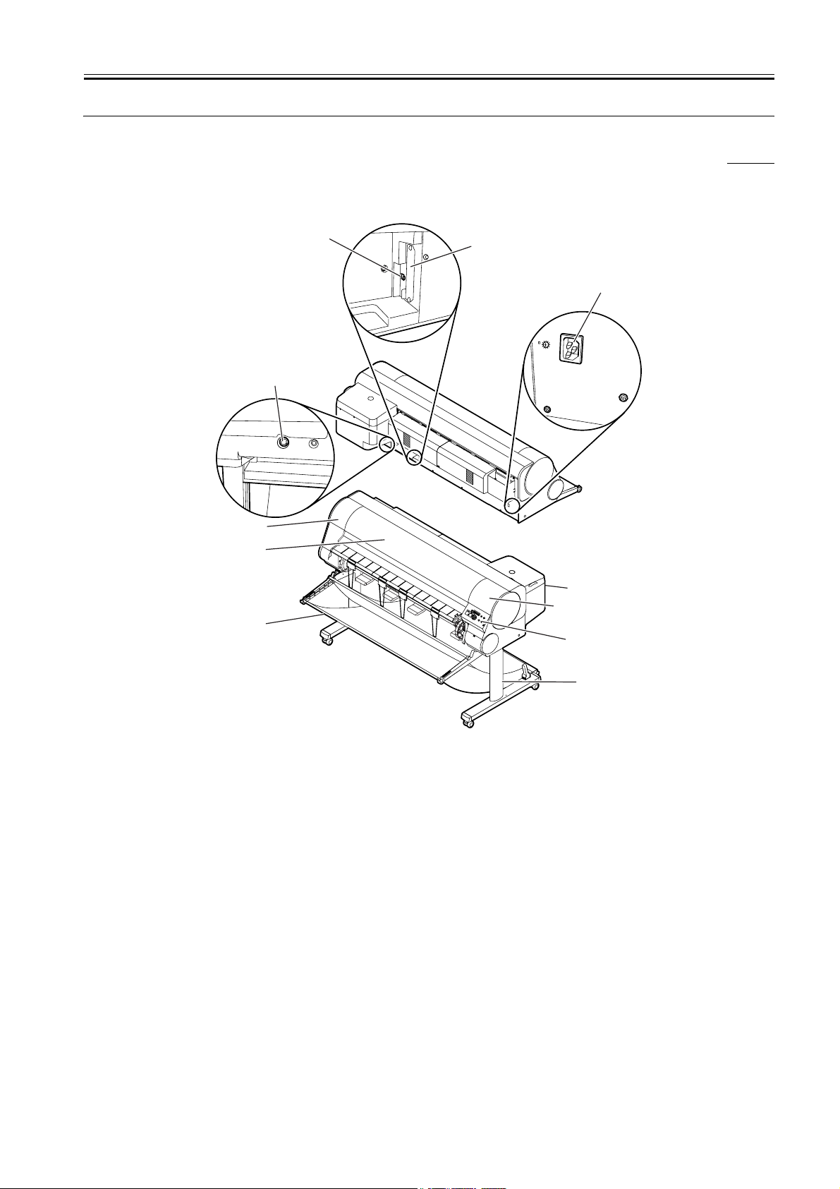
External View of Printer (1/2)
0008-3099
[8]
[9]
[11]
[10]
[6]
[7]
[1]
D
a
t
e
D
a
M
t
e
e
s
s
a
g
e
I
n
f
o
m
a
ti
o
n
P
o
w
e
O
r
K
S
to
p
/
E
j
e
c
t
O
n
li
n
e
O
n
l
i
n
e
M
e
n
[4]
u
[2]
[3]
[1] Right cover [7] Upper cover
[2] Upper right cover [8] USB port
[3] Operation panel [9] Expansion board slots (a network interface
[4] Output stacker [10] Connector for the Media take-up unit
[5] Stand (option except for USA model) [11] Power supply connector
[6] Upper left cover
*1: The Network board is installed as a standard item for USA model.
External View of Printer (2/2)
[5]
F-1-1
T-1-1
board or IEEE1394 expansion board. *1)
1-1

Chapter 1
[12]
[16]
[17] [18]
[21]
F-1-2
T-1-2
[15][13]
[14]
[19] [20]
[12] Ink tank [17] Belt stopper
[13] Print head [18] Snag prevention stay
[14] Roll holder [19] Cleaner brush
[15] Holder stopper [20] Accessory pocket
[16] Hex key wrench [21] Poewr cord
1-2

Chapter 1
1.2 Features
1.2.1 Features
- Reduced size with ink tank placed in rear.
- Printable on a variety of print media with the use of two types of black ink (replaceable).
Photo Black: This ink has excellent gloss and black density for glossy media and proof media.Nearly all types of media can be printed, including glossy
media.
Matte Black: This ink has excellent black density for standard paper, fine art media, and matte media. It cannot be used for glossy media.
- Remaining roll media control made possible by barcode printed on roll media.
- Four-sides borderless printing support (roll media) eliminates tedious cutting and simplifies poster creation.
- High quality photo finish with 2400 x 1200 dpi maximum resolution using highly lightfast, water-proof, and ozone-proof six color (C, M, Y, Bk, MBk,
PC, PM) pigment ink. (Choose either Bk or MBk)
- High-speed printing with bidirectional print control using 1 inch (1280-nozzles) head for each color.
- Tubing type ink supply completely separating print head and large capacity ink tank.
- Support for roll media and cut sheets.
- Roll media with width from 203.2 to 609.6 mm and length up to 18 m can be used.
- Standard carriage mounted cutter enables automatic sheet cutting. In addition, optional cutter unit enables cutting of additional types of media.
- Cut sheet feeding, media discharge, and ink tank replacement can be performed easily from the front.
- Standard support for high-speed USB2.0 interface. Optional support for 10Base-T/100Base-TX TCP/IP network or IEEE1394.
1.2.2 Printhead
On the carriage, disposable printhead is installed, each of which contains six rows of integrated nozzles.
Each row consists of 1280 nozzles, which are arranged in a staggered pattern for printing efficiency.
If print quality does not improve despite carrying out cleaning, the printhead should be replaced with a new one. Generally, it is recommended that the
print head be replaced about 6 months after you have opened the package.
0008-3103
0009-1059
F-1-3
1.2.3 Ink Tank
The ink tank is disposable.
There are six colors: Black (Bk), Photo Cyan (PC), Cyan (C), Photo Magenta (PM), Magenta (M) and Yellow (Y), each using pigment based ink. Either
Black (Bk) or Matte Black (MBk) can be selected for Black.
There are the following features in two kinds of black ink.
-Photo Black
This ink has excellent gloss and black density for glossy media and proof media. Nearly all types of media can be printed, including glossy media.
-Matte Black
This ink has excellent black density for standard paper, fine art media, and matte media. It cannot be used for glossy media.
To install an ink tank, open the right cover of the printer and insert the tank. The printer features a mechanism by which only the correct color ink tank will
fit in its given slot.
When the "No Ink" message is displayed, replace the ink tank with a new one. Also, the ink tanks should generally be replaced 6 months after you have
opened the package.
F-1-4
0009-1061
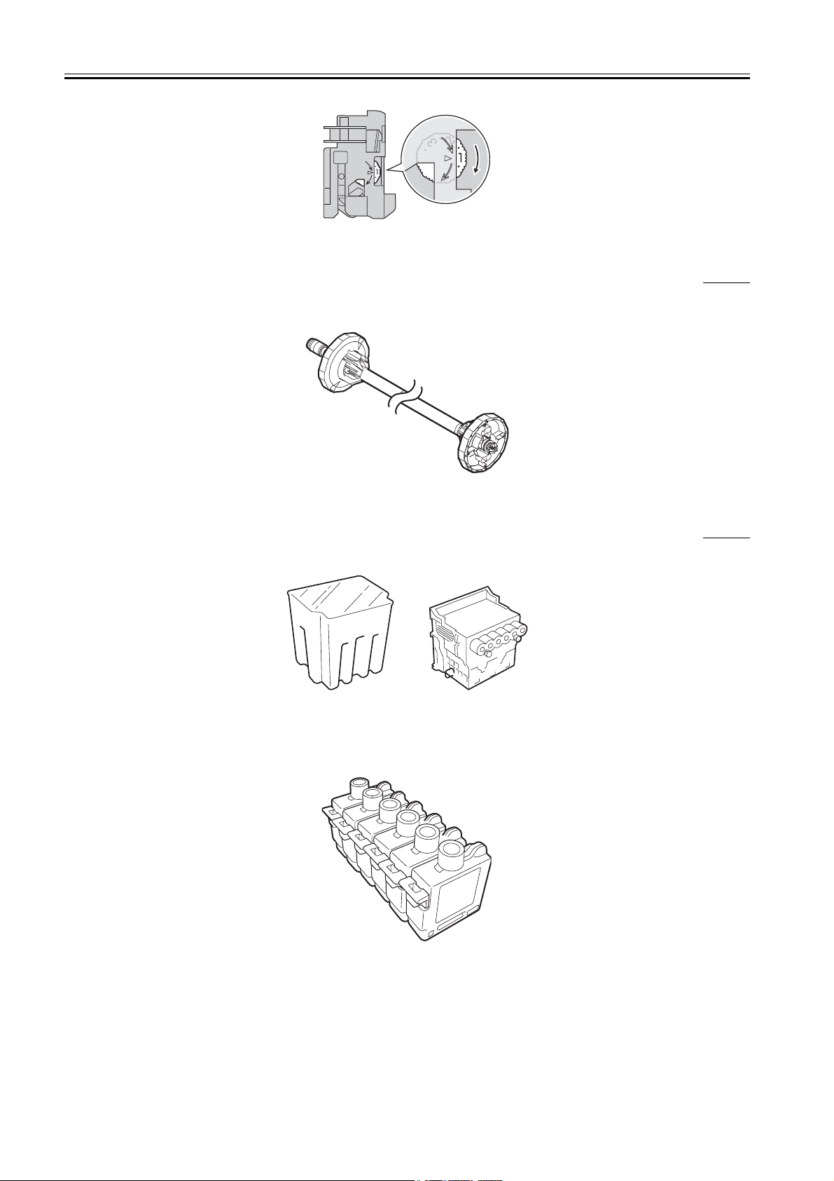
1.2.4 Cutter Unit
A disposable cutter unit is mounted on the carriage.
When the cutter becomes dull, increment the position adjustment dial by 1. If the dial is at 3, replace with a new cutter unit.
0009-1079
1-3
Chapter 1
F-1-5
1.2.5 Roll Holder
A roll holder for a 2-inch inner diameter paper tube is included as standard accessory. Roller holders for 2-inch inner diameter paper tube and 3-inch inner
diameter paper tube are set as option.
Both roll holders lock into the cardboard tube of roll media with an outer diameter not more than 6 inch (150 mm).
0009-1094
F-1-6
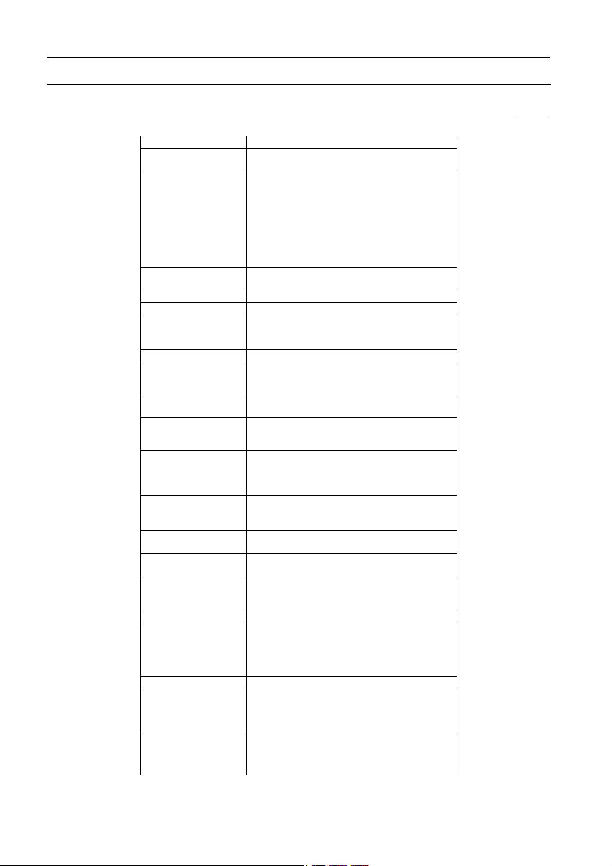
1.2.6 Consumables
Printhead
This consumable printhead is the same as the printhead shipped with the printer.
F-1-7
Ink tank
Seven types of consumable ink tank are available in six colors: Black (Bk), Matte Black (MBk), Photo Cyan (PC), Cyan (C), Photo Magenta (PM), Magenta
(M), and Yellow (Y). They are all identical with the ink tank shipped with the printer.
Each bottle has a life of 6 months from the time the package is opened.
0009-1139
F-1-8
Cutter unit
The consumable cutter unit is the same as the cutter unit shipped with the printer.
1-4

F-1-9
Chapter 1
1-5
Chapter 1
1.3 Product Specifications
1.3.1 General Specifications
Type Bubble jet printer (Desktop type)
Feeding system Roll media: Manual (rear setting)
Feeding capacity Roll media: 1 roll (outer diameter: 150 mm or less)
Delivery method Delivers the media with its printed side up in the forward
Sheet delivery capability 1 sheet (Delivered in outlet stacker)
Cutter Automated replaceable cartridge-type cutter
Type of media See to Product Description > Detailed Specification > Type of
0008-3121
Cut sheet: Manual (front setting)
Standard roll holder: inner diameter of the paper tube: 50.8 mm
(2")
Optional roll holder: inner diameter of the paper tube: 50.8 mm
(2")
Optional roll holder: inner diameter of the paper tube: 76.2 mm
(3")
Cut sheet: 1 sheet
direction
media.
Supported thickness 70 µm to 800 µm
Media size (Roll media) Width: 254mm(10") to 1117.6mm(44")
Media size (Cut sheet) Width: 203.2mm(8") to 1117.6mm(44")
Printable area (Roll media) Area excluding 5 mm from the top, 5 mm from the bottom, and
Printable area (Cut sheet) Area excluding 5 mm from the top, 23 mm from the bottom, and
Printing assurance area
(Roll media)
Printing assurance area (Cut
sheet)
Margins (Roll media) Leading edge 5mm, Trailing edge 5mm, Left edge 5mm, Right
Margins (Cut sheet) Leading edge 20mm, Trailing edge 23mm, Left edge 5mm,
Emulation None
Interface Compliance with USB specification 2.0 standards
Printhead/Ink Tank type Printhead and separate ink tanks
Printhead BCI-1350
Ink tank BCI-1421: Bk, PC, C, PM, M
Length: 210.0mm(8.27") to 18m(709")
*Outer diameter of roll:150mm or less.
Length: 203.2mm(8") to 1574.8mm(62")
5 mm from the left and right edges
* Printable area may depend on the media.
5 mm from the left and right edges
* Printable area may depend on the media.
Inside area excluding 20 mm from the top, 23 mm from the
bottom, and 5 mm from the left and right edges
Inside area excluding 20 mm from the top, 23 mm from the
bottom, and 5 mm from the left and right edges
edge 5mm
Right edge 5mm
Network 10 Base-T/100 Base-TX (compliance with IEEE802.3
standards) (option except for USA model)
Compliant with IEEE1394-1995 standards and P1394a
(Version2.0) (option)
Architecture: Six rows of integrated nozzles arranged in parallel
One row of nozzles: 1280 nozzles arranged in a staggered
pattern
BCI-1441: MBk, Y
Ink type: Pigment ink
Ink capacity: Approx. 330 ml
1-6

Chapter 1
Detection functions (Cover
system)
Detection functions (Ink
passage system)
Detection functions
(Carriage system)
Detection functions (Paper
path system)
Operating noise During printing: Approx. 54dB (A) max. (6.9Bels max.)
Operating environment Operating environment: Temperature 5 deg C to 35 deg C
Print quality guaranteed
environment
Power supply AC100 V to 240 V, 50 Hz/60 Hz
Power consumption
(Maximum)
Power consumption Power save mode
Printer unit dimensions
(WxDxH)
Covers open/close detection: Yes
Ink tank detection: Yes
Ink level detection: Yes
Maintenance cartridge detection: Yes
Waste ink full detection: Yes
Printhead detection: Yes
Carriage position detection: Yes
Carriage home position detection: Yes
Carriage cover open/close detection: Yes
Carriage temperature detection: Yes
Carriage head position detection: Yes
Non-discharging nozzle detection: Yes
Non-discharging nozzles back-up function: Yes
Paper detection: Yes
Paper leading and trailing edge detection: Yes
Paper width detection: Yes
Skew detection: Yes
Paper release lever position detection: Yes
Roll media trailing edge detection: Yes
Remaining roll media detection: Yes
Feed roller rotation detection: Yes
During standby: Approx. 35dB (A) max.
Humidity 10 % to 90 % RH
Print quality guaranteed environment: Temperature 15 deg C to
30 deg C
Humidity 10 % to 80 % RH
Maximum: 160 W max.
100 to 115V: 6 W max.
220 to 240V: 9 W max.
Power off: 1 W max.
* If an option has been mounted, this may be different.
W1,642 mm x D715 mm x H478 mm (not including the stand)
W1,642 mm x D971 mm x H1,075 mm (including the stand)
Weight Weight Approx. 80 kg (without stand)
Weight Approx. 98 kg (including stand)
1-7

Chapter 1
1.4 Detailed Specification
1.4.1 Type of media
Classification Media Type
Photo Photo Glossy Paper, Photo Semi-Glossy Paper, Heavyweight Glossy
Art Fine Art Photo, Fine Art Heavyweight Photo, Fine Art Textured,
Japanese Paper Washi Japanese Paper Washi
Coated Paper Coated Paper, Heavy Coated Paper, Extra Heavyweight Coated
Generic Plain Paper, Plain Paper (High Quality)
CAD CAD Plain Paper, CAD Tracing Paper, CAD Translucent Matte
Proof Proofing Paper 2, Newsprint for Proofing
Synthetic Paper Synthetic Paper, Adhesive Synthetic Paper
Film Back Light Film
Cloth Flame-Resistant cloth, Cloth
0009-8740
T-1-3
Photo Paper, Heavyweight Semi-Glossy Photo Paper
Canvas Matte, Canvas Semi-Glossy
Paper, Colored Coated Paper
Film, CAD clear film
1.4.2 Printing Speed and Direction
Image is used by enlarging JIS SCID No.5 (ISO) to A0 full size.
0009-8505
1-8

T-1-4
Media type Mode Print-
Plain paper, Plain paper (High
Quality)
Coated Paper, Heavy Coated
Paper, Extra Heavy Coated
Paper
Photo Glossy Paper, Photo
Semi-Glossy Paper, Photo
Glossy Paper (HW), Photo
Semi-Glossy Paper (HW),
Special1 - 5
Fine Art (Photo), Fine Art
(Photo HW), Fine Art
(Textured), Canvas (Matte),
Canvas (Semi-Glossy)
Japanese Paper, Synthetic
Paper, Adhesive Synthetic
Paper, Flame-Resistant Cloth,
Cloth
Back Light Film Standard 8-pass 2400x1200dpi Approx. 6.7
Proofing Paper 2 Standard 8-pass 1200x1200dpi Approx. 3.9
Newspaper Proofing Paper 1 - 3Draft 4-pass 1200x1200dpi Approx. 2.0
Color Coated Paper Draft 4-pass 1200x1200dpi Approx. 2.0
Draft 2-pass Bi-directional 1200x1200dpi Approx. 1.3
Standard 6-pass 1200x1200dpi Approx. 3.0
Draft 4-pass 1200x1200dpi Approx. 2.0
Standard 6-pass 1200x1200dpi Approx. 3.0
High 8-pass 2400x1200dpi Approx. 6.7
Standard 8-pass 1200x1200dpi Approx. 3.9
High 8-pass 2400x1200dpi Approx. 6.7
Highest 16-pass 2400x1200dpi Approx. 13.1
Draft 8-pass 1200x1200dpi Approx. 3.9
Standard 8-pass 2400x1200dpi Approx. 6.7
High 16-pass 2400x1200dpi Approx. 13.1
Standard 8-pass 1200x1200dpi Approx. 3.9
High 16-pass 2400x1200dpi Approx. 13.1
High 16-pass 2400x1200dpi Approx. 13.1
High 8-pass 2400x1200dpi Approx. 6.7
Standard 6-pass 1200x1200dpi Approx. 3.0
Standard 6-pass 1200x1200dpi Approx. 3.0
pass
Printing
direction
Print
resolution (dpi)
Print speed *1
min.
min.
min.
min.
min.
min.
min.
min.
min.
min.
min.
min.
min.
min.
min.
min.
min.
min.
min.
min.
min.
Chapter 1
*1: From the time when carriage starts moving under the following environment until the final band is output. Excluding data transfer, processing, or drying
time.
OS: Windows 2000 SP4
PC: Pentium4 2.2GHz/RAM:512MB
Application: Adobe Photoshop 6.0
I/F: USB2.0
Image: ISO JIS-SCID No.5 chart enlarged to A0 size
1.4.3 Interface Specifications
a. USB
1) Interface format
USB 2.0, Full Speed (12Mbit/sec), High Speed (480Mbit/sec)
2) Data transfer
Control transfer
Bulk transfer
3) Signal level
Compliance with USB standards
4) Interface cable
Twisted-pair shielded cable, 5.0 m max.
Compliance with USB standards
Wire materials AWG No. 28, data wire pair (AWG: American Wire Gauge)
AWG No. 20 to No. 28, wire pair
5) Interface connector
Printer side: USB standards, series B receptacle
Cable side: USB standards, series B plug
b. IEEE1394 (option)
0009-8506
1-9

Chapter 1
1) Interface format
Interface complying with IEEE1394-1995, P1394a (Version 2.0) standards
2) Data transfer
Asynchronous transfer
3) Signal level
Input:
Differential input voltage: S100 During negotiation period +173 mV to +260 mV
During data reception +142 mV to +260 mV
S200 During negotiation period +171 mV to +262 mV
During data reception +132 mV to +260 mV
S400 During negotiation period +168 mV to +265 mV
During data reception +118 mV to +260 mV
Output:
Differential output voltage: +172 mV to +265 mV
4) Interface cable
Twisted-pair shielded cable, 4.5 m max.
Compliance with IEEE1394-1995 standards or P1394a (Version 2.0) standards
5) Interface connector
Printer side: IEEE1394 standards, 6-pin connector (socket)
Cable side: IEEE1394 standards, 6-pin connector (plug)
c.Network (option except for USA model)
1) Interface format
Interface complying with IEEE802.3 standards
2) Data transfer
10Base-T/100Base-TX
3) Signal level
Input : threshold
10 Base-T : max +585mV
min +300mV
100 Base-TX : turn-on +1000mV diff pk-pk
turn-off +200mV diff pk-pk
Output:
10 Base-T : +2.2V to +2.8V
100 Base-TX : +0.95V to +1.05V
4) Interface cable
Category 5 (UTP or FTP) cable, 100 m max.
Compliance with ANSI/EIA/TIA-568A or ANSI/EIA/TIA-568B standards
5) Interface connector
Printer side: IEEE802.3 standards, compliance with ANSI X3.263 standards, and ISO/IEC60603-7 standards
Cable side: Compliance with ANSI/EIA/TIA-568A or ANSI/EIA/TIA-568B standards, RJ-45 type
1-10
1.5 Names and Functions of Components
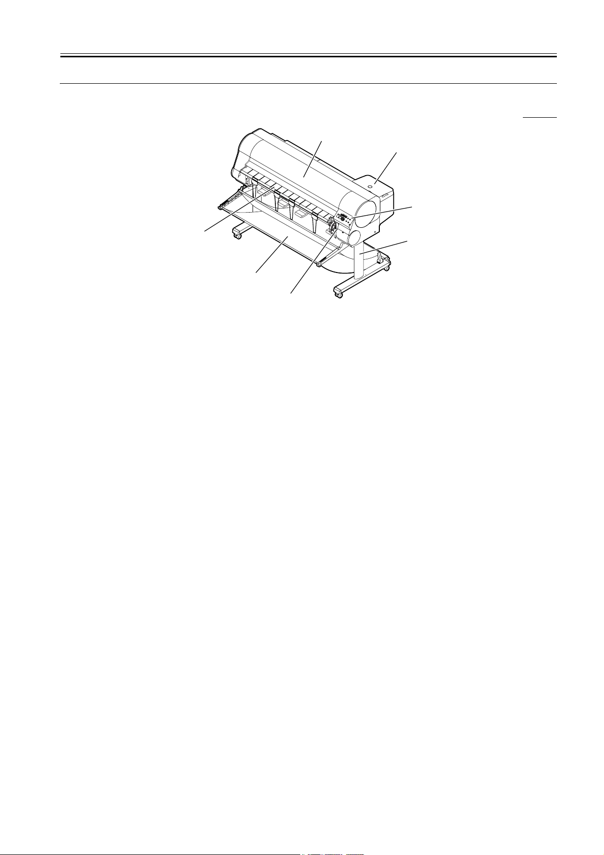
1.5.1 Front
Chapter 1
0009-8428
[1]
[2]
[3]
[7]
[6]
[5]
F-1-10
T-1-5
[4]
[1] Upper Cover Remove this cover to install the print head, to load media, or to
remove sheets of paper jammed in the printer.
[2] Right Cover Open to replace ink tanks.
[3] Operation Panel Provides the display panel and the operation panel buttons.
[4] Stand This is a table designed specially for this printer. Casters are attached
to the legs to make it easy to move. An optional Media Take-up Unit
can also be installed.
[5] Release Lever The lever that releases the media. If you are loading or manually
feeding paper, pull up this lever and open the paperweight bar.
[6] Output stacker A cloth tray that catches print media ejected from the printer.
[7] Paper Catch Tray Printed media is delivered to the paper catch tray. Open the paper
catch tray to load the roll media.
1-11
Chapter 1
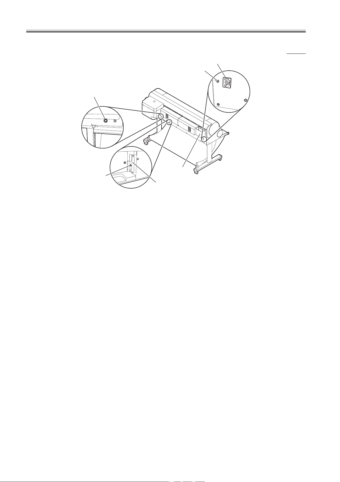
1.5.2 Rear
0009-8429
[1]
[2]
[5]
[6]
[4]
[3]
F-1-11
T-1-6
[1] Power Supply
Provides a connection point for the printer power cord.
Connector
[2] Grounding Wire
Connector
[3] Expansion Board
Slots
Provides a connection point for the grounding wire. (onlly JP
model)
Provided for installing a network interface board or IEEE1394
expansion board.
[4] USB Port This is the communication port for USB High Speed 2.0. Connect
the USB cable here to connect the printer to the computer via USB.
[5] Media Take-up Unit
Provides a connection point for the optional media take-up unit
Connector
[6] Accessory Pocket Holds the printer manual, tools for assembly, and extra
ink tanks.
1-12
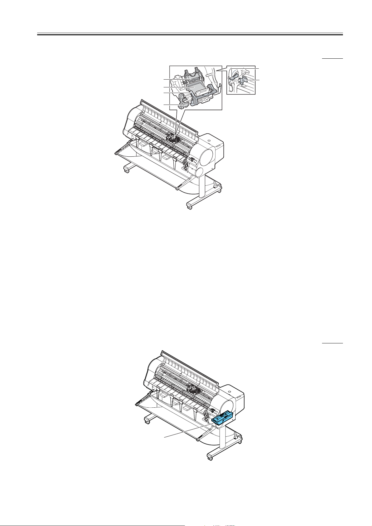
1.5.3 Carriage
Chapter 1
0009-8430
[5]
[1]
[2]
[3]
[4]
[6]
1.5.4 Internal part
F-1-12
T-1-7
[1] Print Head Lock Cover This cover locks and holds the print head in place.
[2] Print Head An important component that is equipped with the print
nozzles.
[3] Print Head Lock Lever This is the lever that locks the printhead lock cover.
Open this lever to open the print head cover.
[4] Cutter Blade The cutter unit that cuts print media automatically.
[5] Print Head Height
Adjustment Lever
Use to adjust the height of the printhead. You will need to
adjust the height of the printhead for high quality printing and
printing on special media.
[6] Shaft Cleaner The shaft cleaner prevents the carriage shaft from becoming
dirty. This cleaner must be replaced at the same time as the
maintenance cartridge is replaced.
0009-8431
D
a
te
D
a
M
te
e
s
s
a
g
e
In
f
o
m
a
tio
n
P
o
w
e
O
r
K
S
t
o
p
/E
j
e
c
t
O
n
li
n
e
O
n
l
in
e
M
e
n
u
[1]
F-1-13
1-13

Chapter 1
[1] Maintenance
Cartridge
T-1-8
The cartridge that vacuums and collects excess ink.
Replace the maintenance cartridge when a message appears
prompting you to replace the cartridge.
1-14
 Loading...