

Canon VB-H751LE Installation Manual
1
Network Camera
2
BIE-7190-000
ENGLISH
This Installation Guide is comprised of pages [1/2] and [2/2]. Please be sure to read the
“Safety Precautions” section for correct use. After reading this Installation Guide, keep it
in a readily accessible location for future reference.
* Some cameras are not available in certain countries or regions.
Caution
Check Included Items
Camera, Screws (M4) x 4 Template Installation Guide (This document)
Setup CD-ROM Warranty Card Ceiling Plate
Waterproof packing Safety Wire, Screws (M3) x 1 Multi-Cable (BK2-0057-000)
Dedicated wrench GND Screw (M3) x 1 LAN Cable Cap
Waterproofing Tape Waterproofing explanation sheet
Zip Tie (for LAN Cable)
Symbols used in this Installation Guide
Parts indicated in the Installation Guide [2/2] with this icon are not included with the
camera, and should be provided by the user.
Installation Guide
Request a professional installer for all installation work. Never try to install
the camera yourself. Doing so may result in unforeseen accidents such as
dropping the camera or electric shock.
Precautions for Installing the Camera Outdoors
When installing the camera outdoors, observe the following
precautions to retain waterproof/dustproof capabilities.
• Completely wrap the cable connections and the ends of cables you
are not using, including the connectors, with waterproof tape up to
the cable jacket, so as not to allow water to enter. Please refer to
the waterproofing explanation sheet for details on how to wrap
the waterproofing tape.
• When mounting the camera onto a wall or other upright
surface, make sure that the cables and composite pipe are
facing down to prevent rain infiltration.
• If wiring by connecting the camera to the composite pipe,
bridge the gap using the conduit box (sold separately).
When connecting the conduit box and the pipe, apply silicon sealant to seal it tightly after
attaching the pipe to prevent water getting in as necessary.
Precautions for Use
Warning
• If you discover defective conditions such as smoke, strange sounds, heat or strange odors,
immediately stop using the camera and contact your nearest dealer.
Fire or electric shock may result from continued use of the product.
• If thunder starts, stop installation or inspection etc. and do not touch the camera or continue
connecting the cable.
• Do not disassemble or modify the camera.
• Do not damage the connecting cable.
• Do not insert foreign objects such as water or metal into the camera.
• Do not use flammable sprays near the camera.
• Do not leave LAN cables, external power supply, or the power connector for the AC adapter (sold
separately) connected when the camera is not in use for long periods.
• Do not use flammable solvents such as alcohol, paint thinner or benzine when cleaning the camera.
Failure to do so may result in fire or electric shock.
Failure to follow the instructions may result in death or serious injury.
Accessories
The following accessories can be purchased separately as necessary. Some accessories are
not available in certain countries or regions.
Conduit Box CB740-VB
Dedicated accessory used to protect wiring cables that cannot be stored above the ceiling.
This can be attached to the composite pipe.
Pendant Mounting Kit PC640-VB
Dedicated accessory used to install the camera to the end of pipe that extends from high
ceilings, such as in big-box stores.
Weather Shield WS700-VB
Dedicated accessory to protect the main camera from rain.
Canon AC Adapter PA-V18
Dedicated AC adapter for this camera.
Safety Precautions
Installation Precautions
Warning
Do not install in the following places:
• Places in strong direct sunlight, near heat-generating objects, or locations subject to high temperatures
• Places near fire sources or flammable solvents (alcohol, thinner, fuel, etc.)
• Places subject to oily smoke or steam
• Confined or enclosed places
Failure to do so may result in fire or electric shock.
• Insulate the ends of cables you are not using.
Failure to insulate may result in fire or electric shock.
Notes on Power Supply
• Only use the dedicated AC adapter (sold separately) for AC power.
•
Do not set any heavy objects on the power cable (or the LAN cable for a PoE+/PoE power supply).
•
Do not pull, forcibly bend, scratch, or modify the power cable (or the LAN cable for a PoE+/PoE power supply).
• Do not cover or wrap the AC adapter (sold separately) with cloth or blankets.
Failure to do so may result in fire or electric shock.
Failure to follow the instructions may result in death or serious injury.
Only for European Union and EEA (Norway, Iceland and Liechtenstein)
These symbols indicate that this product is not to be disposed of with your household waste,
according to the WEEE Directive (2012/19/EU), the Battery Directive
(2006/66/EC) and/or national legislation implementing those Directives.
If a chemical symbol is printed beneath the symbol shown above, in
accordance with the Battery Directive, this indicates that a heavy metal (Hg =
Mercury, Cd = Cadmium, Pb = Lead) is present in this battery or accumulator at
a concentration above an applicable threshold specified in the Battery Directive.
This product should be handed over to a designated collection point, e.g., on an authorized onefor-one basis when you buy a new similar product or to an authorized collection site for recycling
waste electrical and electronic equipment (EEE) and batteries and accumulators. Improper
handling of this type of waste could have a possible impact on the environment and human health
due to potentially hazardous substances that are generally associated with EEE. Your cooperation
in the correct disposal of this product will contribute to the effective usage of natural resources.
For more information about the recycling of this product, please contact your local city
office, waste authority, approved scheme or your household waste disposal service or visit
www.canon-europe.com/weee, or www.canon-europe.com/battery.
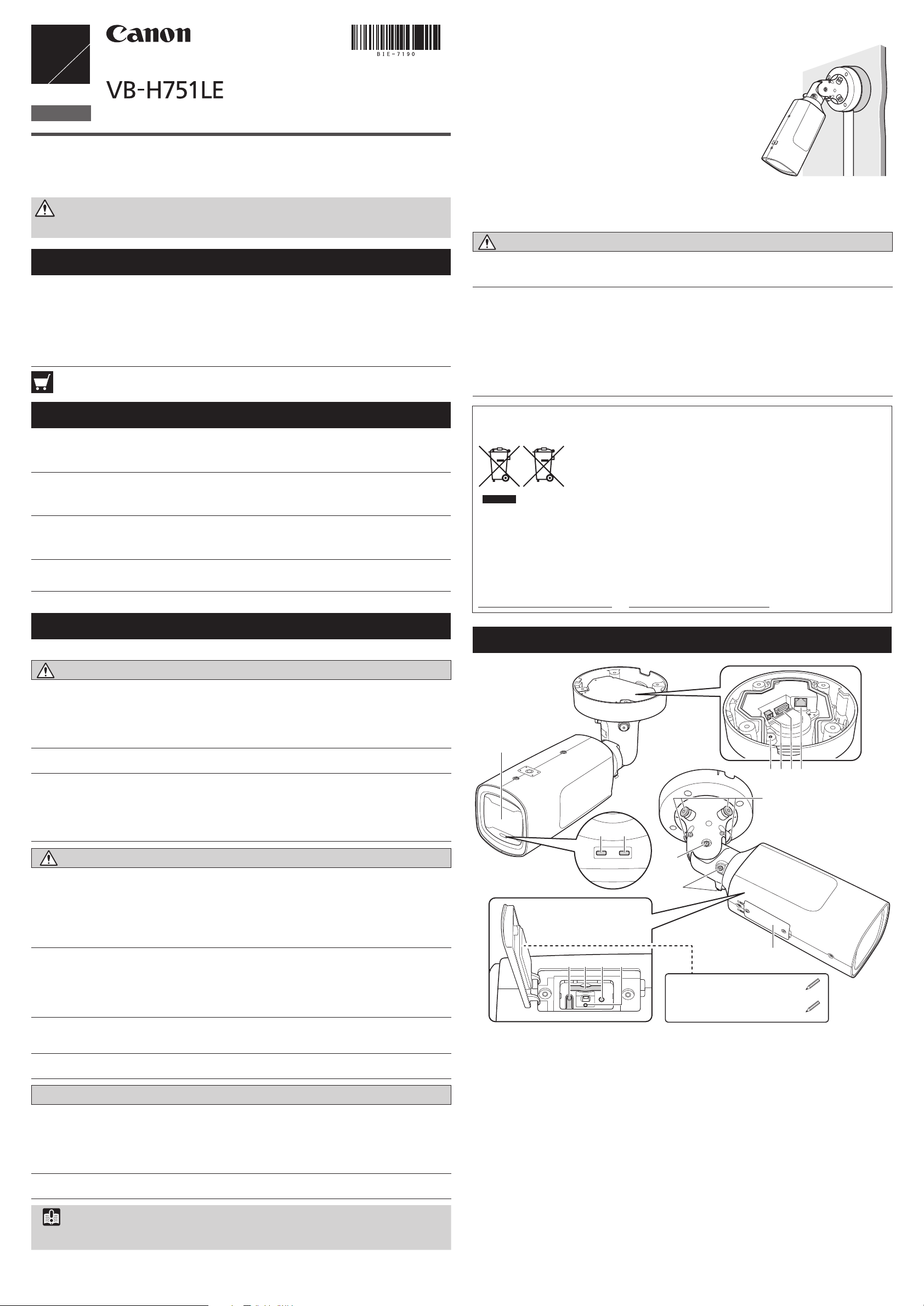
Part Names
1
4 65 7
8
2 3
Caution
For installation or inspection of this camera, consult the dealer where you purchased the product.
• This installation should be made by a qualified service person and should conform to all local codes.
• When installing, make sure the surface is capable of withstanding the total weight of the camera and
accessories, and sufficiently reinforce if necessary.
• Be sure to use installation screws designed for the type of surface the camera is to be installed.
• Periodically check the parts and screws for rust and loosening, in order to prevent injuries and
equipment damage due to falling items.
• Do not install in unstable places, places subject to significant vibration or impact, or places subject to
salt damage or corrosive gas.
• Do not install in places subject to strong winds.
• Do not install where snow can accumulate directly on the camera.
Be sure to attach the safety wire when installing the camera.
•
Failure to do so may result in the camera falling or other accidents.
• Do not touch the edges of metal parts with bare hands.
• Be careful not to get your fingers caught when installing.
Failure to do so may result in injuries.
• Avoid looking directly at the infrared illumination at close distances for long periods of time.
Intense infrared illumination can cause eye damage.
Caution
• Do not install on an unstable surface.
• After turning off the power, do not turn the power on again for at least five seconds.
• Take measures to remove static electricity before performing any procedures.
• If there is condensation, please wait to power on, until the condensation dissipates.
• Please waterproof and dust-proof camera, when installing outdoors.
Failure to do so may result in malfunctions.
• Take care not to damage wiring or piping.
Failure to do so may result in damage to peripheral items.
Failure to follow the instructions may result in injury.
Failure to follow the instructions may result in property damage.
Important
We recommend the installation of a lightning arrester (a surge protection device) as a measure against
failures caused by lightning strikes. Please refer to our website for details.
9
10
12 13 14 15
Serial_ _ _ _ _ _ _ _ _ _ _ _ _ _ _ _ _
MAC_ _ _ _ _ _ _ _ _ _ _ _ _ _ _ _ _ _
1. Lens protector / 2. LED (Orange) / 3. LED (Blue)*1 / 4. GND screw hole /
5. Power connection terminal / 6. I/O & Audio combination connector /
7. 100Base-TX LAN connector / 8. Pan axis adjustment screw / 9. Tilt axis adjustment screw /
10. Rotation axis adjustment screw / 11. Memory card cover / 12. Reset switch*
13. Memory card slot / 14. Reboot switch / 15. LED (Blue)*
1
*
On: when powered on, during reboot, during normal use / Off: when [Turn Off] is selected
(please refer to the “Operation Guide”)
2
Please refer to the “Operation Guide” for the method to reset the camera.
*
1
11
2
/
When the temperature within the camera is low (heater activated)
When the unit is powered by a 24 V AC/ PoE+ power source, the heater unit can be used.
The heater unit will be activated automatically when the temperature within the camera is low.
The orange LED will be lit, until the camera has warmed up enough to start transferring video.
Once the temperature within the camera has reached the level where it can transfer the video
once again, the orange LED will turn off.
The contents of this guide are subject to change without any prior notice.
When there is condensation on the lens protector after being turned on
3
2
1
GND
Condensation can occur on the inside of the lens protector, when the power has been
turned on for the first time after installation, or after not being turned on for a long time. The
condensation will dissipate after the power has been left on a while (this may take more than
a day at the longest), please wait to use the camera until you can confirm that the image is
correctly visible.
Specifications
Please refer to the Appendix – Specifications for specifications not listed below.
Lens 2.4x optical zoom (4x digital zoom) lens (electric drive)
Viewing Angle For 16:9 aspect ratios
Horizontal: 124.3° (W) – 50.5° (T) Vertical: 66.9° (W) – 28.4° (T)
For 4:3 aspect ratios
Horizontal: 90.6° (W) – 37.9° (T) Vertical: 66.9° (W) – 28.4° (T)
Pan Angle Range 344° (-217° – +127°)
Tilt Angle Range 93° (-3° – +90°)
Rotation Angle Range 344° (±172°)
Network Terminal*
* Use a category 5 or better LAN cable, 100 m (328 ft.) or less in length.
Audio Input Terminal 3.5 mm ( 0.14 in.) mini-jack connector (monaural)
(common for LINE IN & MIC IN)
Audio Output Terminal
(LINE OUT)
External Device I/O Terminal
Memory Card SD Memory Card, SDHC Memory Card, SDXC Memory Card Compatible.
Operating Environment Temperature:
Operating Temperature Range (including direct sun exposure)
AC, PoE+: -50°C – +55°C (-58°F – +131°F)
DC, PoE: -10°C – +55°C (+14°F – +131°F)
Start-up Temperature Range (including direct sun exposure)
AC, PoE+: -30°C – +55°C (-22°F – +131°F)
DC, PoE: -10°C – +55°C (+14°F – +131°F)
Humidity: 5% – 85% (without condensation)
Storage Environment Temperature: -30°C – +60°C (-22°F – +140°F)
Humidity: 5% – 90% (without condensation)
Installation Method Ceiling mount/Surface mount
Power Supply
AC Adapter: PA-V18 (100 – 240 V AC) (sold separately)
External power source: 24 V AC/12 V DC
IR Illumination Range (T) 30 m (98.4 ft.) (When using 24 V AC, PoE+)
(T) 20 m (65.6 ft.) (When using 12 V DC, PoE)
Power Consumption PoE+: Max. approx. 20.1 W*
AC Adapter PA-V18: Max. approx. 12.5 W (100 V AC) Max. approx. 12.6 W (240 V AC)
DC: Max. approx. 11.2 W AC: Max. approx. 20.9 W
*
*
Weight Approx. 2550 g (5.63 lb.)
Dust-resistant/
Waterproof Specification
– Camera is at 0° when attached to the ceiling and facing straight down, and 90° when at
a horizontal position
LAN x 1 (RJ45, 100Base-TX (auto/full-duplex/half-duplex))
3.5 mm ( 0.14 in.) mini-jack connector (monaural)
Input x 2, Output x 2
PoE: PoE power supply via LAN connector (IEEE802.3at Type1/Type2 compliant)
1
PoE: Max. approx. 10.2 W*
1
Class 4 power sourcing equipment (requests 30.0 W)
2
Class 0 power sourcing equipment (requests 15.4 W)
IP66
2
Important
•
The power supply should be within the following voltage range.
• 24 V AC: Voltage fluctuation within ±10% of 24 V AC (50 Hz or 60 Hz ±0.5 Hz or less)
Current supply capacity of at least 1.0 A per camera
• 12 V DC: Voltage fluctuation within ±10% of 12 V DC
Current supply capacity of at least 1.5 A per camera
• When using a 12 V DC battery power supply, be sure to connect resistors of at least 0.5 – 1.0 Ω/20 W
in series to the power line.
• For an external power supply, use a double-insulated device.
Recommended Power Cables [Reference]
Cable (AWG) 24 22 20 18 16
12 V DC maximum cable length m (ft.) 5 (16.4) 9 (29.5) 14 (45.9) 23 (75.5) 32 (105.0)
24 V AC maximum cable length m (ft.) 11 (36.1) 18 (59.1) 29 (95.1) 46 (150.9) 64 (210.0)
Use UL cable (UL-1015 or equivalent) for 12 V DC or 24 V AC wiring.
AC Adapter
Please use the dedicated AC adapter (sold separately).
Remove the power connector attached to the AC adapter, then connect the multi-cable
included in the package, to the power connector, as shown in the following diagram.
Green (fat)
Blue (fat)
White
AC Adapter
Multi-Cable
Brown (fat)
Black
Insulate
External Device I/O Terminals
External device I/O terminals consist of two input and output systems each. Viewer can be
used to check external device input status and control output to an external device (please
refer to the “Operation Guide”).
Use the included multi-cable to connect to external device input/output terminals.
1: BROWN External device input 1 IN1 (+)
2: RED External device input 2 IN2 (+)
3: BLACK External device input 1, 2 IN1 (-), IN2 (-)
4: ORANGE External device output 1 OUT1A
External Device Input Terminals (IN1, IN2)
External device input terminals consist of two sets (IN1, IN2) of two terminals, with the negative
terminals connected to the camera interior GND. Connecting cables to the positive and
negative terminals and opening or closing the circuit notifies the Viewer.
5: YELLOW External device output 1 OUT1B
6: GREEN External device output 2 OUT2A
7: BLUE External device output 2 OUT2B
Connecting the Camera
Power Connection
Please be sure to read the user manual for the dedicated power supply before use.
Note
• Power supply should conform to all local codes.
• The power supply should also comply with IEC/UL60950-1 (SELV/LPS) standards.
PoE+/PoE (Power over Ethernet)
Power can be supplied to the camera by using a LAN cable connected to a PoE+/PoE HUB
that conforms to the IEEE802.3at Type2 (PoE+)/Type1 (PoE) standard.
Important
• Check with your dealer for more information about PoE+/PoE HUB and Midspan technology.
Midspan (a LAN cable power supply device) is a device that, like a PoE+/PoE HUB, supplies power
to the camera via a LAN cable.
• Some PoE+/PoE HUBs allow the limitation of power for each port, but applying limits may interfere
with performance. If using this type of PoE+/PoE HUB, do not limit the operating power.
• Some PoE+/PoE HUBs have limits for the total power consumption for the ports, which can interfere
with performance when multiple ports are in use. For more information, check the instruction guide
for your PoE+/PoE HUB.
• When the camera is connected to both a PoE+/PoE HUB and an external power supply (12 V DC or
24 V AC), power will be supplied in the following order of precedence.
External power supply (24 V AC) > PoE+/PoE HUB > External power supply (12 V DC)
However, when connecting power from both, certain combinations could cause problems such as
unstable network connections. If a problem arises, disable one of the power supplies.
Multi-Cable
To prevent cable connections from shorting out, wrap each individual connection with
insulating tape, and then wrap all of the cables with waterproofing tape.
Please connect all of the connectors to the camera, even if you do not plan to use the external
power supply or the external device/ audio I/O.
Camera side
OUT (White)
External Power Supply
12 V DC or 24 V AC input can be used. Use the included multi-cable to connect to the camera
power connection terminal. 12 V DC can be connected in a non-polar configuration.
1: BLUE (fat) 24 V AC / 12 V DC non-polar 3: GREEN (fat) FG (frame ground)
2: BROWN (fat) 24 V AC / 12 V DC non-polar
IN (Black)
Important
When connecting sensors and switches, connect terminals that are electrically isolated from the
respective power and GND.
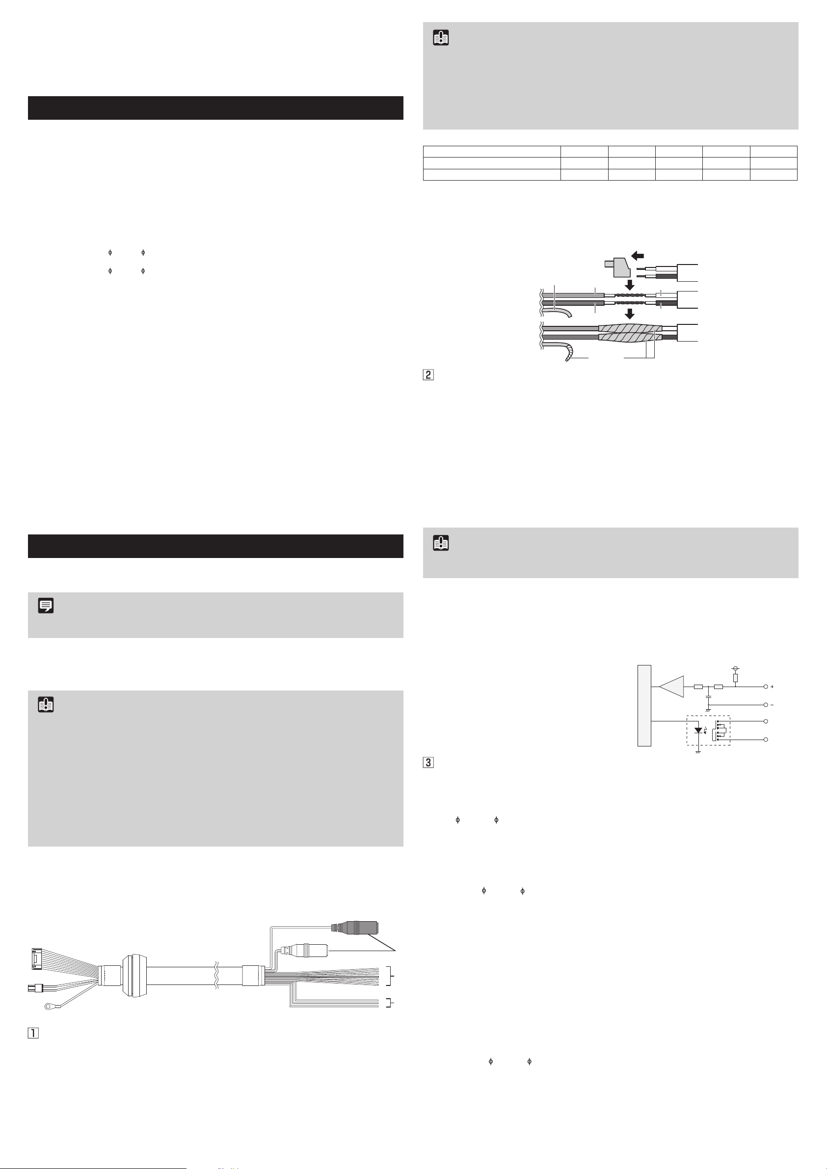
External Device Output Terminals (OUT1, OUT2)
External device output terminals consist of two sets (OUT1, OUT2) of two terminals. The sets
have no polarity. Controls from the Viewer can be used to open and close the circuit between
the terminals. Using optical couplers, the output terminals are isolated from the camera’s
internal circuit.
The load connected to the output terminals
should be within the following rating range.
Rating between output terminals:
Maximum voltage 50 V DC
Continuous load current at or below 100 mA
Internal Connection Diagram
+3.3 V
10 kΩ 10 kΩ
0.1 µF
1 kΩ
External device
Input terminal
IN1, IN2
On resistance: Max. 30 Ω
External device
Internal controller
Output terminal
OUT1, OUT2
Audio Input/Output Terminals
Each audio input/output terminal has one input system and one output system.
Connecting the camera to an audio input/output device such as a microphone or a speaker
with an amplifier allows you to send/receive audio through the Viewer.
Use the included multi-cable to connect audio input/output devices to the camera.
Use the
device with the multi-cable.
Although the camera has a single audio input system, it supports two types of microphone
input: LINE IN and MIC IN. Before using the audio input, please confirm the [Audio Input] in the
Setting Page (please refer to the “Operation Guide”). LINE IN is selected by default.
Input terminal:
• Dynamic MIC IN
* Supported microphones: Output impedance: 400 – 600 Ω
• Condenser MIC IN
1
* Supported microphones: Condenser microphones with plug-in power support
7
1
3
• LINE IN
* Use a microphone with an amplifier.
Connect the camera to a speaker with an amplifier. Audio can be sent to the speaker from the
Viewer.
Output terminal:
Output level: Max. 1 Vp-p
* Use a speaker with an amplifier.
CANON INC.
30-2, Shimomaruko 3-chome, Ohta-ku, Tokyo 146-8501, Japan
CANON EUROPA N.V.
Bovenkerkerweg 59, 1185 XB Amstelveen, The Netherlands
© CANON INC. 2017 Printed in Japan
3.5 mm ( 0.14 in.) monaural mini-jack connector to connect an audio input/output
Audio Input Terminal Common LINE IN/MIC IN (monaural input)
3.5 mm ( 0.14 in.) mini jack (monaural)
Input impedance: 1.5 kΩ ±5%
Input impedance (microphone bias resistance): 2.2 kΩ ±5%
Microphone power supply: plug-in power (voltage: 2.3 V)
Input level: Max. 1 Vp-p
Audio Output Terminal LINE OUT (monaural output)
3.5 mm ( 0.14 in.) mini jack (monaural)
 Loading...