

Page 1
NETWORK CAMERA
COPY
User’s Manual
VB-C50FSi
Please read this User’s Manual carefully before operation.
Be sure to read the “a Safe Use of Equipment” section before using
this equipment. Store this manual in a readily accessible location for
future reference.
VB-C50Fi
Page 2

Introduction
COPY
Thank you for purchasing the Canon Network Camera VB-C50FSi/VB-C50Fi (referred to hereafter
as the VB-C50FSi/VB-C50Fi).
This User’s Manual describes how to set up and use the VB-C50FSi/VB-C50Fi. Read this manual
carefully before using the VB-C50FSi/VB-C50Fi to ensure effective operation. In particular make sure
that you read the “a Safe Use of Equipment” in this manual, as well as the supplied CD-ROM ReadMe
file.
For the latest information, please refer to Canon Web site.
Exclusion of Liability
If the Product is connected to a recording device (for example a VCR), Canon Inc. accepts
no responsibility whatsoever for any financial losses that may be incurred as a result of
the loss of recorded information or images, regardless of the internal or external cause of
the loss.
On Copyrights
Videos, images or sounds taken or recorded with your VB-C50FSi/VB-C50Fi may not be utilized
or published, without consent of copyright holders, if any, except in such a way as permitted for
personal use under relevant copyright law.
Notes
1. The unauthorized transfer of all or any part of the contents of this Manual is forbidden.
2. The contents of this Manual are subject to change without notice.
3. Every effort has been made to ensure that this Manual is flawless. However, if you find any
oversights, please let us know.
4. Notwithstanding the above, Canon accepts no responsibility for any effects resulting from the
use of this Manual.
Trademark Notices
● Canon and Canon logo are registered trademarks of Canon Inc.
● Microsoft and Windows are registered trademarks of Microsoft Corporation in the United States
and other countries.
● Windows is legally recognized as Microsoft Windows Operating System.
● Java and all Java-based marks are trademarks or registered trademarks of Sun Microsystems,
Inc. in the United States and other countries.
● Other brand or product names in this manual may be trademarks or registered trademarks of
their respective companies.
This product uses software based on the GNU General Public License (GPL), GNU Lesser General
Public License (LGPL) and the BSD License. For each of the licenses, see GPL.txt, LGPL.txt and
COPYING.txt in the LICENSE folder on the CD-ROM.
If you require the source code for a program based on GPL or LGPL, please contact either the place
of purchase or your nearest Canon Sales Company.
ii
Page 3
Introduction
COPY
Usage Notice of Audio (VB-C50FSi only)
* Features related to audio transmission (audio sent from camera servers to viewers)
written in this manual can be only used with the Model Name “VB-C50FSiN”.
Please refer to P.1-10 to confirm the Model Name of your VB-C50FSi.
● The audio and video may be out of sync.*
● The audio stream may be interrupted according to the performance of your PC and the
network environment.
● You cannot record audio with the viewer software.*
● You can receive audio using the Viewer for PC or the Admin Viewer.*
● You can send audio and video to up to 50 clients. However, if there are a large number
of clients, the audio stream may be interrupted.*
● The audio stream may be interrupted if you use a proxy server.
● The audio stream may be interrupted if you use anti-virus software.
Request concerning disclosure of live videos and audio
With respect to the disclosure of live videos and audio, we request that sufficient
consideration be given to matters of privacy and rights not to be photographed.
Canon considers the following points concerning such matters when it operates camera
sites for which it has been responsible to install and operate:
● We take measures such as adding limitations on zoom magnifications so that people
cannot make special specifications.
● When videos are taken of specific buildings, interiors and the like, we install the camera
only after receiving approval from the administrator.
Please note that the operator of the camera site and not Canon has full responsibility
regarding the disclosure of live videos and audio.
* Audio features are only available on the VB-C50FSi.
■ European Union (and EEA) only.
This symbol indicates that this product is not to be disposed of with your
household waste, according to the WEEE Directive (2002/96/EC) and your
national law. This product should be handed over to a designated collection
point, e.g., on an authorized one-for-one basis when you buy a new similar
product or to an authorized collection site for recycling waste electrical and
electronic equipment (EEE). Improper handling of this type of waste could have a possible
negative impact on the environment and human health due to potentially hazardous
substances that are generally associated with EEE. At the same time, your cooperation in
the correct disposal of this product will contribute to the effective usage of natural resources.
For more information about where you can drop off your waste equipment for recycling,
please contact your local city office, waste authority, approved WEEE scheme or your
household waste disposal service.
For more information regarding return and recycling of WEEE products, please visit
www.canon-europe.com/environment.
(EEA: Norway, Iceland and Liechtenstein)
© Copyright 2007 CANON INC.
ALL RIGHTS RESERVED
iii
Page 4
Package Contents
COPY
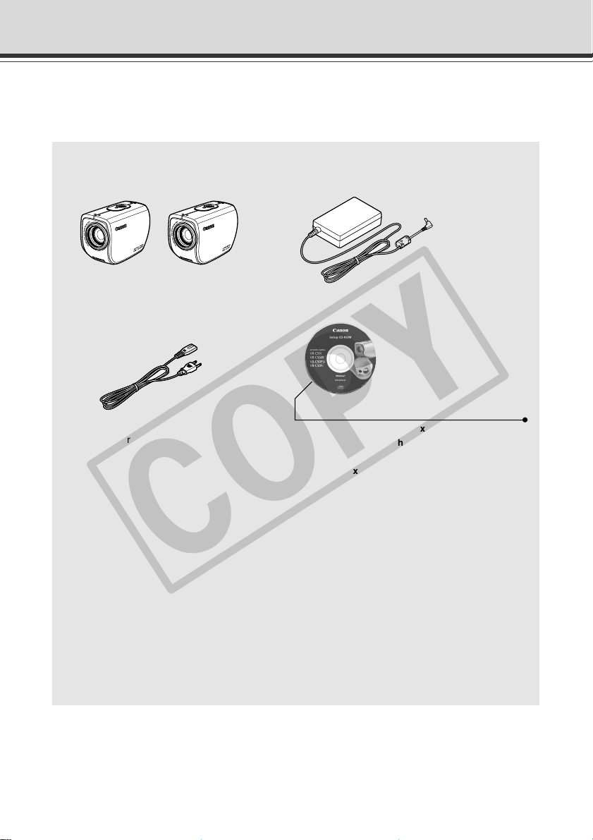
The VB-C50FSi/VB-C50Fi package contains the following items. If any of these items is missing,
please contact the retailer from which you purchased the product.
1. VB-C50FSi main unit
(or VB-C50Fi main unit )
3. AC cable (1 meter/3 ft.)
(VB-C50Fi NTSC model only)
* The cable length may differ depending
on the country in which the product was
purchased.
5. User’s Manual
(This document)
6. Warranty card
(NTSC model only)
2. AC adapter PA-V16
(VB-C50Fi NTSC model only)
4. CD-ROM
CD-ROM contents
ReadMe-J.txt (Japanese text containing
precautions etc. other than those in this
document)
ReadMe-E.txt (English text containing
precautions etc. other than those in this
document)
VBSetup.exe (Initial settings tool → P.2-8)*
MANUAL folder (PDF versions of this document
and the Viewer software User’s Manual)*
vbfiles folder (File system sets of sample pages
etc.)
LICENSE folder (License documents for
software built into the VB-C50FSi/VB-C50Fi)
VBTools folder (Bundled software installer set)*
SOUND folder (Sound sample files for Audio
Playback)
* For the latest information of the bundled
software and manual, please refer to Canon
Web site.
iv
Page 5

Contents
COPY
Introduction ............................................................................ ii
Package Contents .................................................................. iv
How to Read This Manual...................................................... ix
a
Safe Use of Equipment....................................................... x
Maintenance .............................................................................................................. xv
Chapter 1 Before Using the VB-C50FSi/VB-C50Fi
Features of the VB-C50FSi/VB-C50Fi .......................................................... 1-2
Hardware and Software Requirements ....................................................... 1-4
Viewer Software ....................................................................................................... 1-4
VB Initial Setup Tool ................................................................................................. 1-5
VB Administration Tools ........................................................................................... 1-5
VBCollector .............................................................................................................. 1-5
Multipoint Recording Software for Monitoring Use (Sold separately) ...................... 1-8
System Components and Their Operation ................................................. 1-9
Multi-Terminal Module VB-EX50 (Sold Separately) .................................. 1-11
Chapter 2 Setting Up
Setup Workflow ............................................................................................. 2-2
1. Set Up the Camera .................................................................................... 2-4
Using the Wide Converter ........................................................................................ 2-5
2. Connect the Camera to the Network ....................................................... 2-6
Turning the Power ON and OFF .............................................................................. 2-7
3. Perform Initial Settings for the Camera .................................................. 2-8
4. Check Operation of the Camera ............................................................ 2-11
5. Install the Software ................................................................................. 2-13
Viewer Software Overview ......................................................................... 2-14
Viewer Software Types .......................................................................................... 2-14
Features of the Viewer Software ............................................................................ 2-14
Chapter 3 Basic Settings
What Can I Do on Each of the Settings Pages? ......................................... 3-2
Accessing the Settings Title Page ............................................................... 3-3
Settings Title Page ........................................................................................ 3-4
Setting Up the Administrator Password and Ethernet etc.
(System and Network) ....................................................................... 3-5
Setting Camera Control, Image Size and Quality (Camera and Video) .... 3-8
Presetting Best Shot (Preset) .................................................................... 3-12
v
Page 6

Contents
COPY
Setting Up the HTTP, Camera and Audio Servers (Server) ..................... 3-15
Setting User Access Privileges (Access Control) ................................... 3-20
Setting the Date and Time (Date and Time) .............................................. 3-23
Setting Up Name Server Address and Mail etc. (Miscellaneous) ........... 3-25
Using the Administration Tools (Administration Tools) .......................... 3-28
Chapter 4 VB Administration Tools
Overview of VB Administration Tools ......................................................... 4-2
Installing the VB Administration Tools ...................................................................... 4-2
VBAdmin Startup Panel ........................................................................................... 4-3
Panorama Creation Tool .......................................................................................... 4-3
View Restriction Tool ................................................................................................ 4-3
Preset Setting Tool ................................................................................................... 4-3
Schedule Setting Tool .............................................................................................. 4-4
Log Viewer ............................................................................................................... 4-4
Admin Viewer .......................................................................................................... 4-4
Starting Up VB Administration Tools .......................................................... 4-5
View Restriction Tool .................................................................................... 4-7
View Restriction Tool Display Screen ...................................................................... 4-8
Setting View Restrictions ....................................................................................... 4-10
Preset Setting Tool...................................................................................... 4-13
Preset Setting Tool Display Screen ........................................................................ 4-14
Setting Presets ....................................................................................................... 4-16
Preset Tour ............................................................................................................. 4-19
Schedule Setting Tool................................................................................. 4-22
Schedule Setting Tool Display Screen (Toolbar) .................................................... 4-23
Normal Schedule ................................................................................................... 4-24
Special Schedule ................................................................................................... 4-28
Resetting Schedule Settings .................................................................................. 4-32
Setting Up Service ................................................................................................. 4-33
Timer Setting Tool .................................................................................................. 4-34
Motion Detection Setting Tool ................................................................................ 4-37
Night Mode Setting Tool ......................................................................................... 4-48
External Device Input Setting Tool ......................................................................... 4-50
External Device Output Setting Tool ...................................................................... 4-53
Log Viewer ................................................................................................... 4-58
Viewing the Log ..................................................................................................... 4-59
Admin Viewer .............................................................................................. 4-61
Starting Up Admin Viewer ...................................................................................... 4-62
Operating External Devices and Motion Detection ................................................ 4-62
Enabling/Disabling View Restrictions ..................................................................... 4-64
Operating a Camera .............................................................................................. 4-64
vi
Page 7

Camera-Specific Functions .................................................................................... 4-66
COPY
Sending and Receiving* Audio (VB-C50FSi only).................................................. 4-67
Shade Correction ................................................................................................... 4-69
Auto Reconnection Function .................................................................................. 4-69
Restoring the Default Exposure and Focus Settings When Closing the Admin Viewer ..
Chapter 5 Creating Web Pages for Video Distribution
Web Pages for Video Distribution ............................................................... 5-2
Viewer Overview ........................................................................................... 5-4
Viewer for Java ........................................................................................................ 5-4
Viewer for PC ........................................................................................................... 5-5
Viewing Sample Pages ................................................................................. 5-6
Using the Viewer for Java to Distribute Videos .......................................... 5-7
Using the Viewer for Java to Create a Web Page ................................................... 5-7
Saving Web Page Data ............................................................................................ 5-8
Example of Using the Viewer for Java to Create a Web Page ................................ 5-9
Viewer for Java Parameters ................................................................................... 5-17
Using the Viewer for PC to Distribute Videos ........................................... 5-21
Setting Up the Web Server .................................................................................... 5-21
Creating wvh Files ................................................................................................. 5-22
Example of a Web page Using the Viewer for PC ................................................. 5-23
Distributing Videos Using a Browser Only ............................................... 5-24
Displaying the Live Video at Access as a Still Picture ........................................... 5-24
Displaying a Specified Number Of Live Video Frames As a Video at Access ....... 5-24
Displaying Live Video from a Specified Zoom Magnification as Still Pictures ........ 5-25
Example of Video Distribution Using One Global Address .................... 5-26
Distributing Still Images to a Mobile Phone ............................................. 5-27
Overwriting Sample Pages .................................................................................... 5-28
Chapter 6 Using the Picture Recording Function
Using the Still Picture Recording Function
Linked to an External Device ........................................................... 6-2
Sample Application Combining a Door-opening Sensor .......................................... 6-2
Using the Audio Playback/Recording Function
Linked to an External Device ........................................................... 6-4
Sample Application Combining a Speaker, Microphone and Door-opening Sensor ....
Using the Still Picture Recording Function
with a Predetermined Schedule ....................................................... 6-6
Sample Application Using a Timer ........................................................................... 6-6
Using the Motion Detection Function with a Predetermined Schedule ... 6-8
Sample application in combination with a warning device ....................................... 6-8
Contents
4-70
6-4
vii
Page 8

Contents
COPY
Using VBCollector ...................................................................................... 6-11
Installing VBCollector ............................................................................................. 6-12
Starting Up VBCollector ......................................................................................... 6-13
Registering a Server .............................................................................................. 6-13
Registering Tasks ................................................................................................... 6-16
Executing and Canceling Tasks ............................................................................. 6-18
Details Displayed on the Task View ....................................................................... 6-20
Starting/Stopping the Service ................................................................................ 6-20
Automatic Downloading by Notification .................................................................. 6-21
Viewing Recorded Images and Playing Back Recorded Audio.............................. 6-23
Viewing Logs .......................................................................................................... 6-32
Setting Retention Period and Disk Space .............................................................. 6-36
Chapter 7 Appendix
Troubleshooting ............................................................................................ 7-2
Log Messages ............................................................................................... 7-4
The VB-C50FSi/VB-C50Fi Log Messages ............................................................... 7-4
The VBCollector Log Messages ............................................................................ 7-12
Specifications ............................................................................................. 7-16
External Device I/O Terminals ................................................................................ 7-17
System Configuration ................................................................................ 7-18
Example of Basic System Configuration – Viewing Videos Using a Viewer .......... 7-18
Viewer Software Functions .................................................................................... 7-18
Sample Network Configurations ............................................................... 7-19
Sample LAN Environment Configuration ............................................................... 7-19
Sample Configuration in an ISP Environment ........................................................ 7-19
Upgrading the Firmware Remotely ........................................................... 7-20
Restoring the Factory Default Settings .................................................... 7-21
Restoring the Factory Default Settings from the Administration
Restoring the Factory Default Settings from the Reset Switch .............................. 7-22
Factory Default Setting .............................................................................. 7-23
Data Capacity of Recorded Pictures and Audio ...................................... 7-25
Amount of Memory ................................................................................................. 7-25
Frame Sizes ........................................................................................................... 7-25
Amount of Audio Data ............................................................................................ 7-26
Index ............................................................................................................ 7-27
Tools Page via a Web Browser ................................................................. 7-21
viii
Page 9

How to Read This Manual
COPY
For information about setting
up the VB-C50FSi/VB-C50Fi
NETWORK
CAMERA
User’s
Manual
P
le
a
B
se
e
sure
th
re
is
ad
fu
e
to
th
q
tu
u
read
is
re
ip
ins
m
re
e
fe
the
tru
n
t.
ren
c
S
“
tio
a
c
to
e
n
re
.
S
m
afe
th
a
n
is
u
U
m
al
se
a
ca
n
of E
u
re
a
fu
l
quipm
in
lly
a
b
re
e
ent”
fo
ad
re
ily ac
section
o
p
e
c
ra
es
tio
sib
before
n
.
le
lo
c
using
a
tio
n
fo
r
User’s Manual
(This document)
Read this manual
carefully before
using the VBC50FSi/VB-C50Fi.
For information about
using the Viewer
This manual describes
how to use the Viewer
for Java and the Viewer
for PC.
Viewer Software
User’s Manual
(Viewer-E.pdf)
Sections where the user
should refer to this
manual are indicated by
the d icon
accompanied by the
relevant page number.
ix
Page 10
a Safe Use of Equipment
COPY
An exclamation point, within a triangle, is intended to alert the user to the presence of
a
important operating and maintenance (servicing) instructions in the literature
accompanying the equipment.
a Important Warnings
a CAUTION:
TO REDUCE THE RISK OF ELECTRIC SHOCK, DO NOT REMOVE COVER (OR
BACK). NO USER-SERVICEABLE PARTS INSIDE. REFER SERVICING TO
QUALIFIED SERVICE PERSONNEL.
The serial number of this equipment may be found on the rear side of the VBC50FSi/VB-C50Fi. No others have the same serial number as yours.
You should record the number and other vital information here and retain this book
as a permanent record of your purchase to aid identification in case of theft.
Date of Purchase
Dealer Purchased from
Dealer Address
Dealer Phone No.
Model No. VB-C50FSi or VB-C50Fi
Serial No.
For Users in the UK (PA-V16)
When replacing the fuse only a correctly rated approved type should be used and
be sure to re-fit the fuse cover.
The AC adapter can be connected to the VB-C50FSi/VB-C50Fi from a standard
AC power outlet. Please check your instruction manual to make sure that your
VB-C50FSi/VB-C50Fi is compatible with this adapter.
– The socket-outlet should be installed near the equipment and should be easily
– Unplug the apparatus from the wall outlet before cleaning or maintaining.
a Important Operational Instructions
accessible.
a WARNING:
TO REDUCE THE RISK OF ELECTRIC SHOCK, DO NOT EXPOSE THIS
EQUIPMENT TO RAIN OR MOISTURE.
a CAUTION:
TO REDUCE THE RISK OF ELECTRIC SHOCK AND TO REDUCE ANNOYING
INTERFERENCE, USE THE RECOMMENDED ACCESSORIES ONLY.
x
Page 11
a
COPY
Safe Use of Equipment
FDA regulation
This Network Camera has not been evaluated by the Food and Drug Administration
(FDA) for use as a medical device. When incorporated into a system with medical
applications, FDA regulations may apply. Therefore, please consult your legal
advisor to determine whether FDA regulations apply.
FCC NOTICE
Network Camera, Model Name: VB-C50FSiN, VB-C50FSiP, VB-C50FiN, VB-C50FiP
This device complies with Part 15 of the FCC Rules. Operation is subject to the
following two conditions: (1) This device may not cause harmful interference,
and (2) this device must accept any interference received, including interference
that may cause undesired operation.
Note: This equipment has been tested and found to comply with the limits for a
Class B digital device, pursuant to Part 15 of the FCC Rules. These limits are
designed to provide reasonable protection against harmful interference in a
residential installation. This equipment generates, uses and can radiate radio
frequency energy and, if not installed and used in accordance with the
instructions, may cause harmful interference to radio communications.
However, there is no guarantee that interference will not occur in a particular
installation. If this equipment does cause harmful interference to radio or
television reception, which can be determined by turning the equipment off and
on, the user is encouraged to try to correct the interference by one or more of
the following measures:
- Reorient or relocate the receiving antenna.
- Increase the separation between the equipment and receiver.
- Connect the equipment into an outlet on a circuit different from that to which
the receiver is connected.
- Consult the dealer or an experienced radio/TV technician for help.
Use of shielded cable is required to comply with class B limits in Subpart B of
Part 15 of FCC Rules.
Do not make any changes or modifications to the equipment unless otherwise
specified in the manual. If such changes or modifications should be made, you
could be required to stop operation of the equipment.
Canon U.S.A. Inc.
One Canon Plaza, Lake Success, NY 11042, U.S.A.
Tel No. (516) 328-5600
Canadian Radio Interference Regulations
This Class B digital apparatus complies with Canadian ICES-003.
Réglementation canadienne sur les intérferences radio
Cet appareil numérique de la classe B est conforme à la norme NMB-003 du
Canada.
Dieses Produkt ist zum Gebrauch im Wohnbereich, Geschäfts- und
Gewerbebereich sowie in Kleinbetrieben vorgesehen.
xi
Page 12

a
COPY
Safe Use of Equipment
a IMPORTANT SAFETY INSTRUCTIONS
In these safety instructions, the word
“equipment” refers to the Canon Network
Camera VB-C50FSi/VB-C50Fi and all its
accessories.
1. Read Instructions - All the safety and
operating instructions should be read before
the equipment is operated.
2. Retain Instructions - The safety and operating
instructions should be retained for future
reference.
3. Heed Warnings - All warnings on the
equipment and in the operating instructions
should be adhered to.
4. Follow Instructions - All operating and
maintenance instructions should be followed.
5. Cleaning - Unplug this equipment from the
wall outlet before cleaning.
Wipe the equipment with a clean soft cloth. If
necessary, put a cloth in diluted neutral
detergent and wring it well before wiping the
equipment with it. Finally, clean the
equipment with a clean dry cloth. Do not use
benzene, thinner or other volatile liquids or
pesticides as they may damage the product’s
finish. When using chemically-treated
cleaning cloths, observe those precautions
accordingly.
6. Accessories - Do not use accessories not
recommended in this manual as they may
be hazardous. Always use specified
connection cables. Connect devices correctly.
7. Water and Moisture - Hazard of electric shock
- Do not use the equipment near water or in
rainy/moist situations. Do not put a heater
near this equipment.
8. Placing or Moving - Do not place on an
unstable cart, stand, tripod, bracket or table.
The equipment may fall, causing serious
injury to a child or adult, and
serious damage to the
equipment. An equipment and
cart combination should be
moved with care.
Quick stops, excessive force, and uneven
surfaces may cause the equipment and cart
combination to overturn.
9. Power Sources - The PA-V16 AC adapter
should be operated only from the type of power
source indicated on the marking label. If you
are not sure of the type of power supply to your
home, consult your equipment dealer or local
power company.
10. Polarization - The PA-V16 AC adapter is
equipped with a polarized 2-prong plug (a plug
having one blade wider than the other).
The 2-prong polarized plug will fit into the
power outlet only one way. This is a safety
feature. If you are unable to insert the plug
fully into the outlet, try reversing the plug. If
the plug still fails to fit, contact your electrician
to replace your obsolete outlet. Do not defeat
the safety purpose of the polarized plug.
11. Power Cord Protection - Power cords should
be routed so that they are not likely to be
walked on or pinched by items placed upon
or against them. Pay particular attention to
plugs and the point from which the cords exit
the equipment.
12. Outdoor Antenna Grounding - If an outside
antenna is connected to the equipment, be
sure the antenna is grounded so as to provide
some protection against voltage surges and
built-up static charges. Section 810 of the
National Electrical Code, ANSI/NFPA No.701984, provides information with respect to
proper grounding of the mast and supporting
structure, grounding of the lead-in wire to an
antenna discharge unit, size of grounding
conductors, location of antenna, antenna
discharge unit, connection to grounding
electrodes, and requirements for the
grounding electrode. See figure 1.
xii
Page 13

a
COPY
Safe Use of Equipment
fig-1
EXAMPLE OF ANTENNA GROUNDING AS
PER NATIONAL ELECTRICAL CODE
ANTENNA
LEAD IN WIRE
GROUNDING
CLAMP
ELECTRIC
SERVICE
EQUIPMENT
NEC — NATIONAL ELECTRIC CODE
13. Lightning - For added protection of this
equipment during a lightning storm, or when
it is left unattended and unused for long
periods of time, disconnect it from the wall
outlet and disconnect the antenna. This will
prevent damage to the equipment due to
lightning and power-line surges.
14. Power Lines - An outside antenna system
should not be located in the vicinity of
overhead power lines or other electric light
or power circuits, or where it can fall into such
power lines or circuits. When installing an
outside antenna system, extreme care should
be taken to keep from touching such power
lines or circuits as contact with them might
be fatal.
15. Overloading - Do not overload wall outlets and
extension cords as this can result in a risk of
fire or electric shock.
16. Object and Liquid Entry - Never push objects
of any kind into this equipment through
openings as they may touch dangerous
voltage points or short out parts that could
result in a fire or electric shock. Be careful
not to spill liquid of any kind onto the
equipment.
17. Servicing - Do not attempt to service this
equipment yourself as opening or removing
covers may expose you to dangerous voltage
or other hazards. Refer all servicing to
qualified personnel.
ANTENNA
DISCHARGE
UNIT (NEC
SECTION 810-20)
GROUNDING
CONDUCTORS
(NEC SECTION
810-21)
GROUNDING CLAMPS
POWER SERVICE
GROUNDING ELECTRODE
SYSTEM
(NEC ART 250. PART H)
18. Damage Requiring Service - Disconnect this
equipment from the wall outlet and all power
sources including batteries, and refer
servicing to qualified service personnel under
the following conditions.
a. When the power-supply cord or plug is
damaged.
b. If any liquid has been spilled onto, or
objects have fallen into, the equipment.
c. If the equipment has been exposed to rain
or water.
d. If the equipment does not operate normally
even if you follow the operating instructions.
Adjust only those controls that are covered
by the operation instructions. Improper
adjustment of other controls may result in
damage and will often require extensive
work by a qualified technician to restore
the equipment to its normal operation.
e. If the equipment has been dropped or the
cabinet has been damaged.
f. When the equipment exhibits a distinct
change in performance. This indicates a
need for service.
19. Replacement Parts - When replacement parts
are required, be sure the service technician
has used replacement parts that are specified
by Canon or that have the same
characteristics as the original part.
Unauthorized substitutions may result in fire,
electric shock or other hazards.
20. Safety Check - Upon completion of any
service or repairs to this equipment, ask the
service technician to perform safety checks
to determine that the equipment is in safe
operating order.
21. Do not install the equipment in the following
locations as this can cause a fire or electric
shock:
- Hot locations
- Close to a fire
- Very humid or dusty locations
xiii
Page 14

a
COPY
Safe Use of Equipment
- Locations exposed to direct sunlight
- Locations exposed to salt spray
- Close to flammable solvents (alcohol,
thinners, etc.)
22. When any of the following occurs,
immediately switch OFF the equipment,
unplug it from the main power supply and
contact your nearest Canon supplier. Do not
continue to use the equipment as this can
cause a fire or electric shock.
- The equipment emits any smoke, heat,
abnormal noise, or unusual odor.
- A metal object falls into the equipment.
- The equipment is damaged in some way.
23. Please observe the following when using the
equipment. Failure to do so can result in a
fire or electric shock.
- Do not use flammable sprays near the
equipment.
- Do not subject the equipment to strong
impacts.
24. Make sure the power line and network cable
are implemented in a safe manner
accordingly to the related technical
regulations.
25. Focusing on the direct sunlight, halogen
lamp or any other high-intensity lamp for a
long time may cause damage to the image
sensor.
xiv
For CA, USA only
Included lithium battery contains Perchlorate Material – special handling may apply.
See www.dtsc.ca.gov/hazardouswaste/perchlorate/ for details.
Page 15
a
COPY
Safe Use of Equipment
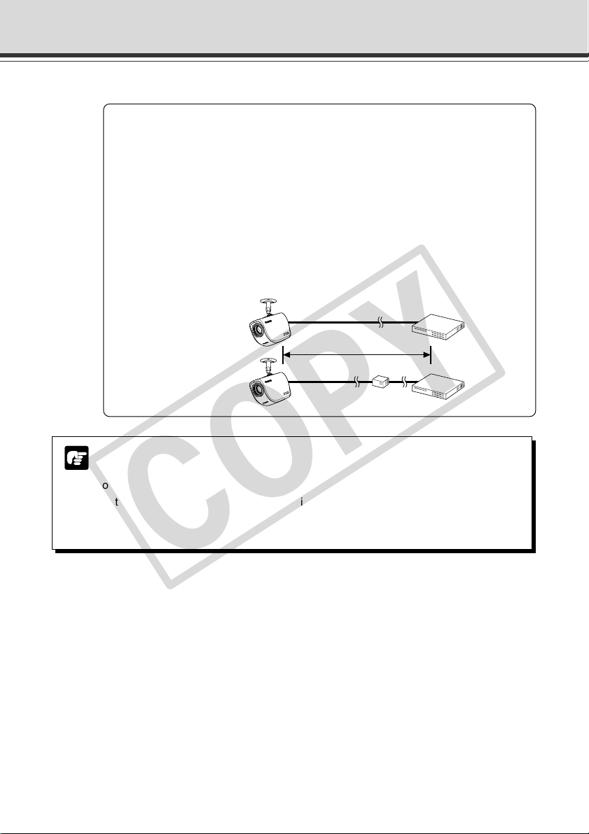
a Notes on Using PoE Hubs
a CAUTION:
● Only use IEEE 802.3af-compliant PoE hubs or midspans.
● When both of a PoE hub and the AC Adapter are connected to the VB-C50FSi,
it runs on the power supply from the PoE hub.
● Some PoE hubs allow the current used by each port to be restricted, but the
VB-C50FSi may not operate correctly when such restrictions are applied. Do
not use such restrictions with the VB-C50FSi.
● Some PoE hubs allow the total current consumed on each port to be restricted,
but the hub may not operate correctly if multiple ports are used.
Refer to the user's manual for your PoE hub.
● Use a cable that conforms to the category 5 or higher standard as the LAN
cable (max. 100 m).
Max.100 m
Midspan Hub
Notes on Using the Motion Detection Function and VBCollector
The Motion Detection Function (→ P.4-37) and VBColletor (→ P.6-11) are not suited
Note
to applications where high levels of reliability are required. Therefore, we recommend
that you not use these functions for monitoring or other purposes if consistently high
levels of reliability are required. Canon accepts no liability whatsoever for faults
resulting from the use of the Motion Detection Function and VBCollector.
PoE hub
xv
Page 16
Maintenance
COPY
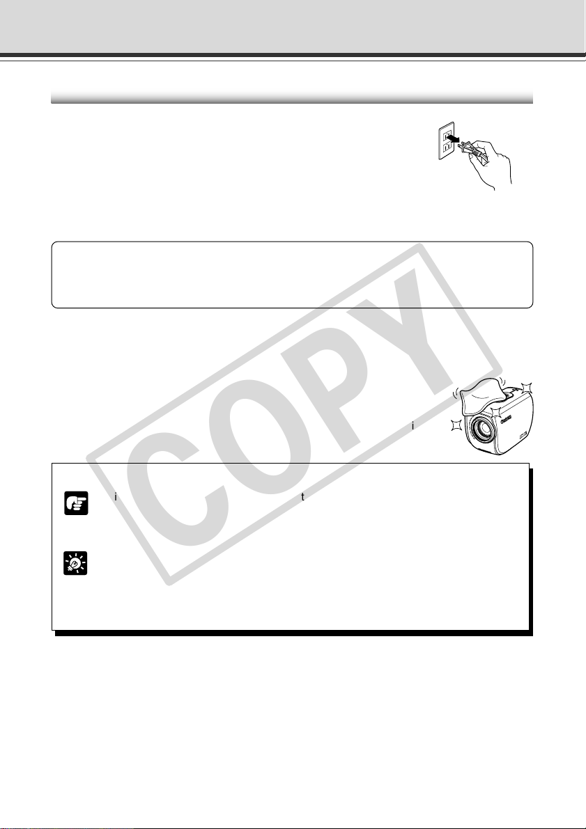
Cleaning the Equipment
1. Unplug the AC adapter from the wall outlet.
If you are using a PoE hub or midspan, disconnect the
LAN cable also (VB-C50FSi only).
2. Carefully wipe the equipment with a soft cloth that has
been moistened with water or a mild detergent.
a WARNING:
Do not use flammable solvents such as alcohol, benzene or thinners.
The use of such substances can cause a fire or electric shock.
3. Wipe with a dry cloth.
4. When you have finished, plug the AC adapter back in to the wall outlet.
Cleaning the Lens
Use a commercially available lens cleaner to remove any soiling from the lens.
● The auto-focus may not function correctly if the surface of the lens is dirty.
● Scratches on the surface of the lens will cause image defects.
Icons Used in This Instruction Manual
Indicates important information that must be observed or actions that are prohibited
during an operation. These notes must be read to prevent possible faults or damage
Note
to the equipment.
xvi
Indicates supplementary information or a reference to an operation. Users are advised
to read these memos.
Tip
Refer to the PDF manual on the supplied CD-ROM.
d
Page 17

Chapter
COPY
Before Using the
VB-C50FSi/VB-C50Fi
This chapter describes the features of the VB-C50FSi/VB-
C50Fi, the hardware and software requirements, and the
name and functions of the system components.
Page 18

Features of the VB-C50FSi/VB-C50Fi
COPY
The VB-C50FSi/VB-C50Fi is a system that distributes live videos via the Internet or an intranet. It
can be used in a wide range of applications, such as distributing live videos from a Web site or
monitoring. The system is configured for the VB-C50FSi/VB-C50Fi and viewer software. Please
use the supplied viewer software for viewing videos distributed by the VB-C50FSi/VB-C50Fi and
controlling cameras (→ P.1-4, 2-14).
Broadband Video Distribution function
The VB-C50FSi/VB-C50Fi is capable of capturing videos at up to 30 fps (NTSC)/25 fps (PAL).
Motion-JPEG type is used to compress video images. For networking, auto-negotiation between
Ethernet 100Base-TX/10Base-T is provided and a leased line or ADSL can also be used through
a router. Since video quality and the frame rate can be freely set, videos can be distributed under
conditions that best suit the network bandwidth.
* Please refer to P.1-10 to confirm whether your VB-C50FSi/VB-C50Fi is PAL model or NTSC model.
Concurrent video is distributed up to 50 clients
Up to 50 clients can view video at the same time from a single VB-C50FSi/VB-C50Fi.
High-performance 26x zoom camera and video distribution server functions
housed in a single unit
The camera capable of full zoom function (high-performance 26x zoom) and its server functions
for distributing videos through a network are compactly housed in a single unit. By simply connecting
a LAN cable and a power supply, the unit can distribute live videos from any location* where it is
installed.
* The unit cannot be installed in locations subject to direct sunlight, high temperatures, high humidity, or
other adverse conditions (→ P.xiii, xiv).
Can be mounted on ceilings, etc.
The VB-C50FSi/VB-C50Fi can be installed on the ceiling or a wall using a mounting arm*.
* The unit cannot be installed in locations subject to direct sunlight, high temperatures, high humidity, or
other adverse conditions (→ P.xiii, xiv).
Built-in PoE (Power over Ethernet) function (VB-C50FSi)
By using an IEEE 802.3af-compliant PoE hub or midspan, power can be supplied to the VBC50FSi via a LAN cable. This simplifies the installation process since there is no need to fit power
outlets at each camera location.
* Use only approved PoE hubs or midspans. (→ P.2-6)
* The LAN cable used to connect the VB-C50FSi to a PoE hub or midspan should be no more than 100
meters long.
Remote camera control from the viewer
The VB-C50FSi/VB-C50Fi comes with two types of viewer software: the Viewer for PC and the
Viewer for Java. The viewers give you full remote control of the camera zoom magnification of the
VB-C50FSi/VB-C50Fi, allowing you to view videos with plenty of ambiance.
Shade Correction function
If the background of an image is bright, making the subject difficult to see, you can adjust the
contrast of the darker areas to make it easier to see. Unlike backlight compensation, the shade
correction feature allows image processing without adversely affecting the existing lighter regions.
1-2
Page 19

Features of the VB-C50FSi/VB-C50Fi
COPY
Zoom Position Preset function
If often-used camera zoom positions and related items are saved in advance as presets, the
camera can be controlled from the viewer by simply selecting a desired preset. Up to 10 presets
can be stored.
View Restriction function
You can set restrictions on camera zoom magnifications. For example, if the VB-C50FSi/VBC50Fi is showing camera footage on the Internet, it is possible to distribute videos while protecting
privacy (→ P.iii, “Request concerning disclosure of live videos and audio”).
More powerful security functions
The destinations for video distributions can be restricted based on passwords. Up to 50 clients
can be registered.
Using preset schedules or links with external devices to record pictures or
audio*
Using the Multi-Terminal Module (→ P.1-11), you can set picture and audio recording* based on
ON/OFF input from an external device and from previously-set schedules. If VBCollector is used,
images and
you can view the images and
* Audio recording and Audio Playback functions are only available on the VB-C50FSi.
* Only available with a particular model of the VB-C50FSi (→ P.iii)
Audio Playback (VB-C50FSi)
Using the Multi-Terminal Module (→ P.1-11), you can connect a speaker with amp to the camera.
Then, you can register your favorite audio files or sample files recorded on a CD-ROM and play
the registered files based on ON/OFF input from an external device and from previously-set
schedules.
Audio transmission (VB-C50FSi)
Using the Multi-Terminal Module (→ P.1-11), you can connect a microphone* and speaker with
amp to the camera and then send and receive
*
Only available with a particular model of the VB-C50FSi (→ P.iii)
sound recorded* by the VB-C50FSi/VB-C50Fi can be automatically collected so that
play back the audio data* on a PC.
audio* via the Viewer.
Before Using the VB-C50FSi/VB-C50Fi
Night mode shooting
By canceling the infrared cut filter, you can increase the camera’s sensitivity and take pictures
even in very dimly lit situations.
Motion detection function
You can perform external device control, video and audio recording* by detecting changes in the
image caused by motion of people or objects.
*
Only available with a particular model of the VB-C50FSi (→ P.iii)
Service settings with schedule function
You can start up motion detection and external device services by setting up a visual and easyto-understand schedule in the calendar.
1-3
Page 20
Hardware and Software Requirements
COPY
For the latest information, please refer to Canon Web site.
Viewer Software (→ d Viewer Software User’s Manual)
The viewer software that is supplied with the VB-C50FSi/VB-C50Fi lets you view the video captured
by the VB-C50FSi/VB-C50Fi and control the camera.
Viewer for Java Ver. 3.6
Operating System/
Web Browser
Java VM MSVM Release 5.0.0.3810 (Java VM provided by Microsoft)
* Java VM must be installed beforehand. If the Java VM provided by Microsoft has not been installed,
please access Sun Microsystems Website to download the Java VM provided by Sun Microsystems.
* Not compatible with Java Plug-in 1.5.0 or later (Java VM provided by Sun Microsystems).
* This viewer may not run stably on operating systems and Web browsers other than those listed above.
Viewer for PC Ver. 3.6
Operating System/
Web Browser
* Must be installed from the supplied CD-ROM (→ P.2-13).
Windows 2000(SP4) / Internet Explorer 6.0(SP1), Netscape 7.1 or 7.2
Windows XP(SP1a) / Internet Explorer 6.0(SP1), Netscape 7.1 or 7.2
Windows XP(SP2) / Internet Explorer 6.0(SP2) or 7.0, Netscape 7.1 or 7.2
Windows Server 2003 Standard Edition / Internet Explorer 6.0, Netscape 7.1 or 7.2
Windows Server 2003 Standard Edition (SP1)
/ Internet Explorer 6.0(SP1) or 7.0, Netscape 7.1 or 7.2
Windows Server 2003 Standard Edition (SP2) / Internet Explorer 6.0(SP2) or 7.0
Windows Server 2003 R2 Standard Edition / Internet Explorer 6.0(SP1) or 7.0
Windows Server 2003 R2 Standard Edition (SP2) / Internet Explorer 6.0(SP2) or 7.0
Java Plug-in 1.4.2 (Java VM provided by Sun Microsystems)
Windows 2000(SP4) / Internet Explorer 6.0(SP1), Netscape 7.1 or 7.2
Windows XP(SP1a) / Internet Explorer 6.0(SP1), Netscape 7.1 or 7.2
Windows XP(SP2) / Internet Explorer 6.0(SP2) or 7.0, Netscape 7.1 or 7.2
Windows Server 2003 Standard Edition / Internet Explorer 6.0, Netscape 7.1 or 7.2
Windows Server 2003 Standard Edition (SP1)
/ Internet Explorer 6.0(SP1) or 7.0, Netscape 7.1 or 7.2
Windows Server 2003 Standard Edition (SP2) / Internet Explorer 6.0(SP2) or 7.0
Windows Server 2003 R2 Standard Edition / Internet Explorer 6.0(SP1) or 7.0
Windows Server 2003 R2 Standard Edition (SP2) / Internet Explorer 6.0(SP2) or 7.0
1-4
● The manual for the viewer software is on the supplied CD-ROM (Viewer-E.pdf).
● Although older versions of viewers can be used, some of the features are different.
Note
Therefore, we recommend you to use the latest version.
Page 21
Hardware and Software Requirements
COPY
VB Initial Setup Tool Ver. 2.1 (→ P.2-8)
This tool is for performing initial settings for the VB-C50FSi/VB-C50Fi.
Operating System/
Web Browser
Windows 2000(SP4) / Internet Explorer 6.0(SP1)
Windows XP(SP1a) / Internet Explorer 6.0(SP1)
Windows XP(SP2) / Internet Explorer 6.0(SP2) or 7.0
Windows Server 2003 Standard Edition / Internet Explorer 6.0
Windows Server 2003 Standard Edition (SP1) / Internet Explorer 6.0(SP1) or 7.0
Windows Server 2003 Standard Edition (SP2) / Internet Explorer 6.0(SP2) or 7.0
Windows Server 2003 R2 Standard Edition / Internet Explorer 6.0(SP1) or 7.0
Windows Server 2003 R2 Standard Edition (SP2) / Internet Explorer 6.0(SP2) or 7.0
VB Administration Tools Ver. 2.2 (→ P.4-2)
This tool lets you set view restrictions and presets visually and easily. You can also set schedules
with this tool.
Operating System/
Web Browser
* Must be installed from the supplied CD-ROM (→ P.2-13).
Windows 2000(SP4) / Internet Explorer 6.0(SP1)
Windows XP(SP1a) / Internet Explorer 6.0(SP1)
Windows XP(SP2) / Internet Explorer 6.0(SP2) or 7.0
Windows Server 2003 Standard Edition / Internet Explorer 6.0
Windows Server 2003 Standard Edition (SP1) / Internet Explorer 6.0(SP1) or 7.0
Windows Server 2003 Standard Edition (SP2) / Internet Explorer 6.0(SP2) or 7.0
Windows Server 2003 R2 Standard Edition / Internet Explorer 6.0(SP1) or 7.0
Windows Server 2003 R2 Standard Edition (SP2) / Internet Explorer 6.0(SP2) or 7.0
Before Using the VB-C50FSi/VB-C50Fi
VBCollector Ver. 3.0 (→ P.6-11)
This tool is for collecting and viewing pictures and audio recorded* by the VB-C50FSi/VB-C50Fi
on a PC.
* Only available with a particular model of the VB-C50FSi (→ P.iii)
Operating System/
Web Browser
Hard Disk Minimum 4 GB required for each camera server. 30 GB or larger recommended
* Must be installed from the supplied CD-ROM (→ P.2-13).
* Pictures saved in VBCollector version 2.1 or earlier cannot be viewed in VBCollector 3.0. During installation,
you can choose whether to uninstall old versions of VBCollector (→ P.6-12).
* If you configure your system to record pictures per second with camera servers and perform the maximum
of 16 tasks (→ P.6-17) at the same time, it is recommended that you use a desktop PC with Pentium 4 2.2
GHz and 512 MB RAM or greater.
* It is recommended that you configure to collect up to 10,000 still pictures/day per a camera server. If the
total amount of still pictures exceeds this value, it may take several minutes to display all the pictures.
* Running VBCollector on a PC that is already running the Network Video Recorder VK-64/VK-16 (sold
separately) is not recommended due to the high CPU load. They should be run on separate PCs.
Windows 2000(SP4) / Internet Explorer 6.0(SP1)
Windows XP(SP1a) / Internet Explorer 6.0(SP1)
Windows XP(SP2) / Internet Explorer 6.0(SP2) or 7.0
Windows Server 2003 Standard Edition / Internet Explorer 6.0
Windows Server 2003 Standard Edition (SP1) / Internet Explorer 6.0(SP1) or 7.0
Windows Server 2003 Standard Edition (SP2) / Internet Explorer 6.0(SP2) or 7.0
Windows Server 2003 R2 Standard Edition / Internet Explorer 6.0(SP1) or 7.0
Windows Server 2003 R2 Standard Edition (SP2) / Internet Explorer 6.0(SP2) or 7.0
(NTFS format)
1-5
Page 22

Hardware and Software Requirements
COPY
Using the VB-C50FSi/VB-C50Fi with Windows XP SP2...
Note
If you use the VB Initial Setup Tool or VBCollector with Windows XP SP2, you will need to
change your Windows firewall settings on your PC.
VB Initial Setup Tool
If you installed the VB Initial Setup Tool on a PC with Windows XP SP2 and try to launch the
tool, you may encounter a Windows Security Alert dialog.
If the Windows Security Alert dialog appears, click Unblock. Once you click the Unblock
button, the dialog box will not be displayed again.
Settings are now complete.
VBCollector
If you installed the VBCollector on a PC with Windows XP SP2 and used the Automatic
Download by Notification function, please follow the procedures as described below.
After installation of the VBCollector:
1. From the Windows Start menu, launch the Control Panel.
2. In Control Panel, select Windows Firewall.
If Windows Firewall is not shown, select “Security Center” and then select “Windows
Firewall”.
3. In the Windows Firewall dialog box, select the Exception tab and then
click Add Program.
4. In the Add a Program dialog box, click Browse.
In the Browse dialog box, select the location where you installed the VBCollector and
enter the file name as “VBCICSM.exe”.
5. In the Windows Firewall dialog box, your program is now listed. Make
sure it is enabled (checked). Click OK to close the dialog box.
Settings are now complete.
If you finish setting the VB Initial Setup Tool (initial settings) or wish to stop the Automatic
Download by Notification function using VBCollector, we recommend you to restore your
Windows firewall settings on your PC.
1. Launch the Windows Firewall dialog box and then select the “Exception”
tab (Refer to 1, 2 and 3 processes of the “VBCollector” for details).
2. Select a program you wish to restore and click “Delete”.
VB Initial Setup Tool: VB Initial Setup Tool Ver. 2.1
VBCollector: VBCICSM.exe
3. A confirmation dialog appears. Click “Yes” to delete the program.
1-6
Page 23
Hardware and Software Requirements
COPY
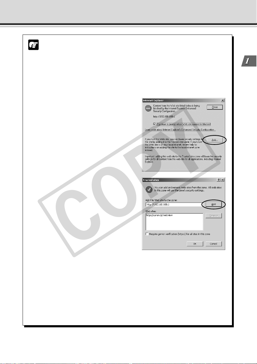
Using the VB-C50FSi/VB-C50Fi with Windows Server 2003...
Note
With Windows Server 2003, the default security level for the Internet or intranet sites in
Internet Explorer is “High”.
As a result, windows such as the settings window do not function normally unless you first
register the site in the contents block dialog box that appears when you access the camera
server top page (→ P.2-11). Register the site to ensure normal functioning.
1. When you access the camera server
top page in Internet Explorer, the
dialog box shown at right appears.
2. Click the [Add] button. The dialog
box for adding Trusted sites then
appears.
If the box for “Require server verification
(https:) for all sites in this zone” is ticked,
remove the tick.
Before Using the VB-C50FSi/VB-C50Fi
3. Enter the IP address of the VB-C50FSi/VB-C50Fi in the “Add this Web
site to the zone” box and then click the [Add] button to register the camera
as a trusted site.
For more information on registering trusted sites, click “Learn more about Internet
Explorer’s Enhanced Security Configuration...” in the dialog box in step 1 and refer to
the summary provided.
If you have enabled the Windows firewall settings, please refer to the “Using the VB-C50FSi/
VB-C50Fi with Windows XP SP2...” (→ P.1-6) and follow the instructions.
1-7
Page 24
Hardware and Software Requirements
COPY
Multipoint Recording Software for Monitoring Use (Sold separately)
Videos distributed from the VB-C50FSi/VB-C50Fi can be recorded, and recorded video can be
displayed with the software.
Network Video Recorder VK-64/VK-16 v1.2 (Viewer System Requirements)
Minimum
CPU Pentium 4 2.2GHz or greater
Operating System Windows 2000 Server (with SP4)
Memory 1 GB RAM or greater
Hard Disk 2GB HDD or greater
Display 1024 × 768 with 16 bit color
Network Video Recorder VK-64/VK-16 v1.2 (Storage Server System Requirements)
CPU Pentium 4 2.2GHz or greater
Operating System Windows 2000 Server (with SP4)
Memory 1 GB RAM or greater
Hard Disk 20 GB HDD or greater, SCSI or IDE, NTFS formatted
The requirements for Storage Server will vary according to the environment you will use (number of Camera Servers,
setting of recording frame rate etc.). Please contact dealers that handle Canon products for further information.
Windows 2000 Professional (with SP4)
Windows XP Professional (with SP2)
Windows Server 2003 Standard Edition (with SP1)
Windows Server 2003 R2
For more than 16 Camera Servers, 1 GB or greater required.
A high performance video card is desirable. With PCI video cards, display performance
may be reduced.
Minimum
Windows 2000 Professional (with SP4)
Windows XP Professional (with SP2)
Windows Server 2003 Standard Edition (with SP1)
Windows Server 2003 R2
For more than 48 Camera Servers, 1.5 GB or greater required.
1-8
Page 25
System Components and Their Operation
COPY
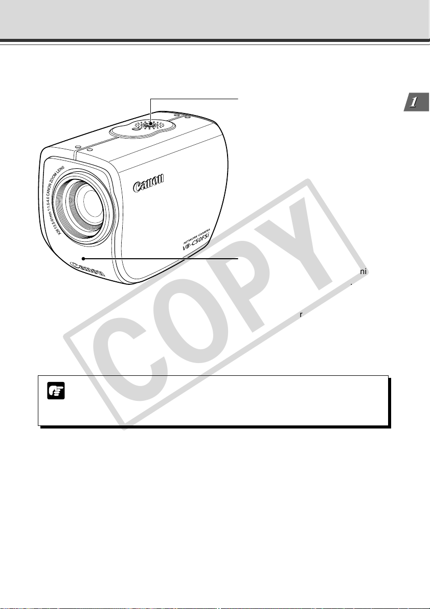
Front
Screw hole for arm mounting
LAN status LED
The LED blinks during communication.
100Base-TX .......................... Green
10Base-T ............................... Orange
* You can set the LED to always light
up even during communication. In
this case, you can select from a
green, orange or red light color. You
can also set the LED not to light up
(→ P.3-27).
Before Using the VB-C50FSi/VB-C50Fi
The only outwardly visible difference between the VB-C50FSi and VB-C50Fi is the
model name printed on the casing. The names and functions of the components are
Note
the same.
1-9
Page 26
System Components and Their Operation
COPY
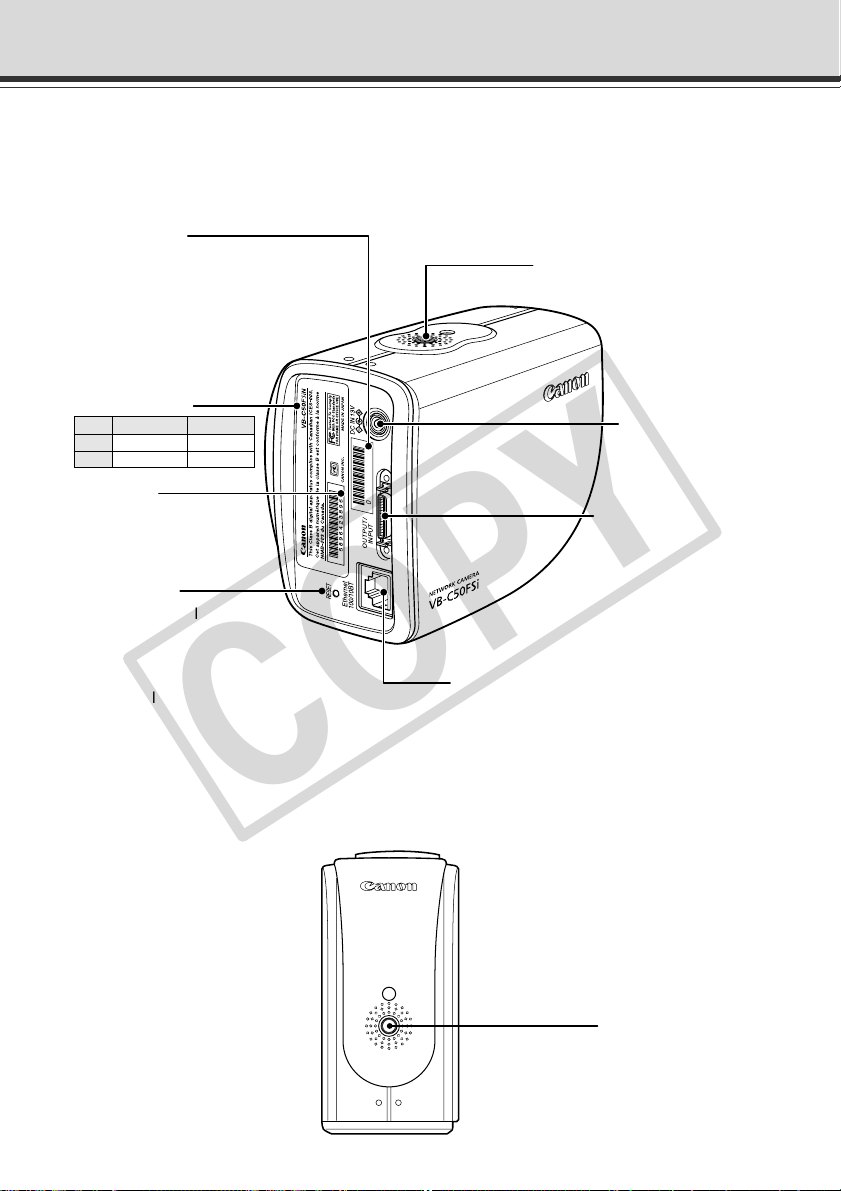
Rear
On the rear of the VB-C50FSi/VB-C50Fi there are the MAC address required for network settings,
a Reset switch that returns the factory default settings and the serial number.
MAC address
The MAC address is required
when setting the IP address
and making other network
settings. Please make a note
of it before installing this unit
(→ P.2-9).
Model Name
VB-C50FSi VB-C50Fi
NTSC VB-C50FSiN VB-C50FiN
PAL VB-C50FSiP VB-C50FiP
Screw hole for arm mounting
Power connection
socket
Serial No.
The serial number for
this unit is shown here.
Reset switch
You can revert all settings of
the unit to the factory default
settings by pressing this
button with a thin-tipped
object while turning on the
power switch, and keeping
the button pressed for more
than five seconds after turning
on (→ P.7-22).
Bottom
00008501F162
Multi-connector
You can connect the
Multi-Terminal Module
VB-EX50 to the VBC50FSi/VB-C50Fi via
the connector (→ P.1-
11).
100/10 BT Ethernet connector
(100Base-TX, 10Base-T Auto-Negotiation)
On the VB-C50FSi, this can also be used to
connect to a PoE hub or midspan.
* The connector is oriented differently on the
VB-C50Fi.
Screw hole for tripod
mounting
1-10
Page 27
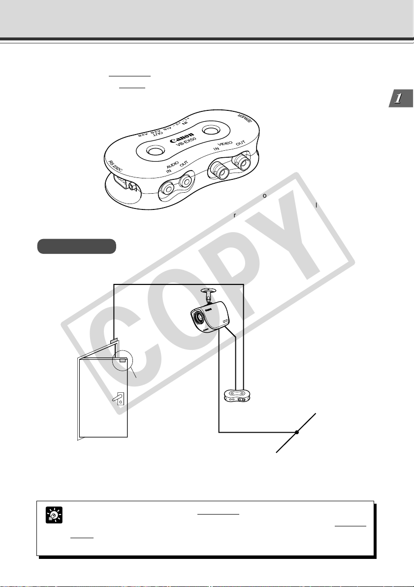
Multi-Terminal Module VB-EX50 (Sold Separately)
COPY
Using the Multi-Terminal Module VB-EX50, you can connect external devices such as different
kinds of sensors, a microphone* and speaker to the unit, and you can store images by sensor
response, or send and receive* audio (→ P.7-17).
Please note that the Multi-Terminal Module VB-EX50 is an optional product and is therefore sold
separately.
* Audio function is available with VB-C50FSi.
* Besides, Audio input is only available with a
particular model of the VB-C50FSi (→ P.iii).
Example of Use
With the Multi-Terminal Module, you can perform settings such as the following.
VB-C50Fi
Before Using the VB-C50FSi/VB-C50Fi
Sensor A
Sensor B
● The door open-close sensor responds when the door is opened and with the VB-C50Fi installed
on the ceiling, you can photograph an image and monitor the scene every second for 3 seconds
before the door opens and for 7 seconds after the door is opened (→ P.6-2).
By using a speaker with amp and microphone* connected to the VB-C50FSi, the
Viewer Administrator can converse with the person in front of the camera, hear and
Tip
record* the sounds in the background (→ P.3-18, 3-19)
* Only available with a particular model of the VB-C50FSi (→ P.iii)
Multi-Terminal Module
VB-EX50
Ethernet
1-11
Page 28

1-12
COPY
Page 29

Chapter
COPY
Setting Up
This chapter explains how to set up the VB-C50FSi/VB-C50Fi,
run initial checks, and confirm that the camera’s images are
displayed correctly.
Page 30
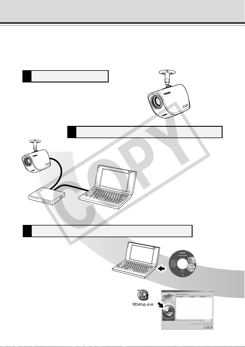
Set up the camera1
Perform initial settings for the camera3
Connect the camera to the network2
LAN cable
VB-C50FSi
Hub
Set up the device.
Make sure the device is set up properly (→ P.2-4).
Connect the camera and your PC via the hub (→ P.2-6).
Insert the CD-ROM provided into your
PC and perform initial settings following
instructions on the screen (→ P.2-8).
Supplied CD-ROM
Setup Workflow
COPY
The flow for setting up and checking the camera’s images involves performing various settings
after the device is set up and your PC and the network are connected via the hub. Then, check to
see if you can display images from the camera.
2-2
Page 31

Install the software5
COPY
Install the required software in advance for operating the
camera (→ P.2-13).
Check operation of the camera4
Access the device with your PC, then display to check the image
from the top page of the camera server (→ P.2-11).
Setup Workflow
Setting Up
2-3
Page 32

1. Set Up the Camera
COPY
Firstly, set up the camera. Read the following carefully and make sure the camera is set up properly.
Mounting the Camera to the Ceiling or Wall
Attach a mounting arm (not included) to the ceiling or a
wall and firmly attach the camera to the arm.
When Using a Tripod
30 mm
(1.18 in.)
or wider
Less than
6.0 mm
(0.24 in.)
Mounting
screw
a WARNING:
Install the camera securely.
● When installing the VB-C50FSi/VB-C50Fi on the ceiling or a wall, contact your Canon
dealer.
● When installing the VB-C50FSi/VB-C50Fi on the ceiling or a wall, check that it is strong
enough to bear the weight of the VB-C50FSi/VB-C50Fi including the mounting arm.
Installation in a weak location could result in the VB-C50FSi/VB-C50Fi falling and causing
serious injury. Check that the ceiling can hold either 3 times the weight of the camera and
arm or 8kgs (whichever is heavier) for 1 minute.
● When attaching the arm to the ceiling, make sure that the screws are tightly fastened.
The arm and camera may fall if the screws are not tightly fastened, which may cause
serious injury.
● At least once a year, check for looseness in the camera installation mount. (If the optional
wide converter is used, check the converter mount also).
● Do not install the arm in a place that shakes or vibrates frequently as the screws may
come loose causing the camera to fall or be damaged, which in turn may cause serious
injury.
2-4
● The MAC address required when making network settings is shown on the rear of the
Note
VB-C50FSi/VB-C50Fi (→ P.1-10). Please make a note of it before installing this unit.
● Always use a tripod mounting screw that is less than 6.0 mm (0.24 in.) in length.
The use of screws 6.0 mm (0.24 in.) long or longer could damage the camera.
Also, the tripod seat used should be at least 30 mm (1.18 in.) in diameter.
Page 33

1. Set Up the Camera
COPY
Using the Wide Converter
The optional Wide Converter WL-37 can be used to provide wide-angle shots (approx. 0.74× the
normal focal distance).
Mount the wide converter correctly so that it is level and fitted securely onto the camera. When
mounted correctly, the wide converter should turn roughly 3 times before stopping.
Wide Converter
● The camera may not operate correctly if a wide converter other than the WL-37
Note
is used.
● Be sure to install the VB-C50FSi/VB-C50Fi firmly because the weight of the camera
increases when the optional Wide Converter WL-37 is attached.
● If you use the optional Wide Converter WL-37, set the zoom lens to the wide-angle
end. If you set the zoom lens to the telephoto end, the image resolution will be
affected and the auto focus might have problems.
Setting Up
○○○○○○
Setup is now complete.
2-5
Page 34

2. Connect the Camera to the Network
COPY
Next, connect the camera. Connect the camera to the network by connecting the camera and PC
via the hub with a LAN cable .
* Do not plug the AC cable power
plug into the wall socket yet.
00008501F162
AC cable
Hub
(Rear of main unit)
AC adapter
LAN
cable
The VB-C50FSi is equipped with a PoE (Power over Ethernet) function. This allows power to be
supplied to the camera from an IEEE 802.3af-compliant PoE hub or midspan via a LAN cable.
PC
2-6
00008501F162
(Rear of main unit)
● Use only approved PoE hubs or midspans.
● For information on how to use the PoE hub or midspan, refer to the user's manual
Note
supplied with the hub.
● The LAN cable used to connect the VB-C50FSi to a PoE hub should be no more
than 100 meters long.
PoE hub
LAN
cable
PC
Page 35

2. Connect the Camera to the Network
COPY
Turning the Power ON and OFF
The VB-C50FSi/VB-C50Fi itself does not have a power switch. You can switch the VB-C50FSi/
VB-C50Fi on by plugging the AC adapter into a wall outlet. The LED flashes when the VB-C50FSi/
VB-C50Fi is communicating. When the power supply is turned ON, the LED momentarily flashes.
Main unit
to AC outlet
AC adapter
AC cable
When power is supplied to the VB-C50FSi via a LAN cable using a PoE hub, connecting the LAN
cable to a hub that is being supplied with power will turn the VB-C50FSi on.
VB-C50FSi
PoE hub
Setting Up
LAN cable
● Wait at least 5 seconds before turning the power back on after shutting it off. Turning
Note
it on too quickly may result in a malfunction. Observe the precautions given in “a
Safe Use of Equipment/a IMPORTANT SAFETY INSTRUCTIONS” (→ P.xii).
● If the picture and audio recording* function is being used, shutting off the
power or restarting the VB-C50FSi/VB-C50Fi will delete all the pictures and
audio*.
* Only available with a particular model of the VB-C50FSi (→ P.iii)
● For information on turning the PoE hub on and off, refer to the user's manual supplied
with the hub.
● When power is supplied to the VB-C50FSi from a PoE hub, the AC adapter can
also be connected to the camera. In this configuration, because the PoE hub power
supply takes priority when power is supplied from the hub, the AC adapter power is
not used. If the PoE supply is cut, the power supply is automatically switched to the
AC adapter.
○○○○○○○○○○○
The network connection is now complete.
2-7
Page 36

3. Perform Initial Settings for the Camera
COPY
Once your PC and the camera are connected, perform the initial settings next. The instructions
here follow on from “2. Connect the Camera to the Network”, where one camera is connected to
a PC as an example.
Installation Example
1. Turn on the network device (in this case, the hub) and then your PC.
● Do not turn on the camera at this stage.
● If you are using a PoE hub or midspan with the VB-C50FSi, do not connect the
Note
2. Insert the CD-ROM provided into your PC and from Explorer etc. double-click
LAN cable.
“VBSetup.exe” to start the VB Initial Setup Tool. Turn on the VB-C50FSi/VBC50Fi. If you are using a PoE hub or midspan, connect the LAN cable.
VB-C50FSi
LAN cable
Hub
2-8
Supplied CD-ROM
○○○○○○○○○
Continued on the following page. a
Page 37

3. The camera connected to the network
COPY
is automatically detected and its MAC
address, IP address and model name
are displayed.
The factory default setting is:
IP address : 192.168.100.1
The MAC address can be found on the white
label attached on the rear of the unit.
Note that VBSetup.exe cannot be used across
subnets.
Click the MAC address to select it, and click
the “Initial Setup” button.
4. Enter the user name “root” and the
factory default password “VB-C50i”
and enter the IP address and subnet
mask.
If you want to specify a default gateway
address, enable the “Set the default route to
Ethernet” check box and then enter the default
gateway address.
Although the time zone and video signal can
also be specified here, there is basically no
need to change the time zone setting.
Once you have entered your settings, click the
“OK” button.
3. Perform Initial Settings for the Camera
Click to select
Setting Up
For Windows XP SP2 users, see “Using the VB-C50FSi/VB-C50Fi with Windows XP
SP2” (→ P.1-6). This Note holds true for users who have turned on Windows Firewall
Note
with Window Server 2003 Standard Edition (SP1).
● The factory default password for the VB-C50FSi/VB-C50Fi is “VB-C50i”.
● The MAC address for this unit is shown on the rear of the VB-C50FSi/VB-C50Fi
Tip
(→ P.1-10).
● The IP address 192.168.100.1 is used as the factory default setting. Please set an
IP address that suits the environment in which the VB-C50FSi/VB-C50Fi is to be
used.
2-9
Page 38

3. Perform Initial Settings for the Camera
COPY
5. A setup progress window appears and
your settings will be saved.
● Set the IP address to a value that suits your environment.
● Where the IP address has been automatically obtained from the DHCP server, you
Note
cannot change the IP address setting from the VB Initial Setup Tool. Change the IP
address from the Network Settings page (→ P.3-6).
● Please consult with your network administrator for the IP address, subnet mask
and default gateway address settings.
●
If 20 minutes or more have passed since the VB-C50FSi/VB-C50Fi was turned on,
the VB-C50FSi/VB-C50Fi stops sending requests for IP addresses allocation and
they cannot be detected using this tool. If this occurs, restart the VB-C50FSi/VBC50Fi.
● To restore the factory default settings, refer to page 7-21.
●
If you are using the Multi-Terminal Module and are changing the connection of the
VB-C50FSi/VB-C50Fi and external camera, be sure to do this after having turned
off the power of these 2 devices. After changing the connection, turn on the external
camera first and then the VB-C50FSi/VB-C50Fi.
2-10
○○○○○○○○○
Initial settings are now complete.
Page 39

4. Check Operation of the Camera
COPY
When you have completed the initial setup, check that the VB-C50FSi/VB-C50Fi works normally.
Use the sample page to simplify checking.
1. Select the MAC address you want to
check operation of and then click the
“Open Test Page”.
2. Your Web browser starts up and the
top page of the camera server appears.
Click the “Using Viewer for Java” or the
“Using Viewer for PC” and check that
the video is displayed properly.
Below is a description of what happens when
you click “Using Viewer for Java”.
Setting Up
Camera Selection box
Allows you to switch cameras
when an external camera is
connected.
For Windows Server 2003 users, see “Using the VB-C50FSi/VB-C50Fi with Windows
Server 2003” (→ P.1-7).
Note
2-11
Page 40

4. Check Operation of the Camera
COPY
● To use the Viewer for Java, you need to install Java VM beforehand. See Canon
Web site for more details.
Tip
● To use the Viewer for PC, you must install the Viewer for PC beforehand (→ P.2-13).
○○○○○○○○○○
Check of operation is now complete.
2-12
Page 41

5. Install the Software
COPY
You must install software to display images from the camera and to manage the camera. There
are 3 types of software you can install.
• VB Administration Tools: Software for managing the camera (→ P.4-2).
• Viewer for PC: Software for displaying images from the camera (→ P.2-14).
• VBCollector: Software that allows you to collect pictures and audio recorded* by the camera on
a PC and view the recorded images and play back the audio data* on the PC (→ P.6-11). When
using older versions of VBCollector, please refer to page 6-12.
* Only available with a particular model of the VB-C50FSi (→ P.iii)
1. Check that all other applications are closed, insert the CD-ROM included with
the camera into the CD-ROM drive of your PC and follow the steps below.
1 Double-click [My Computer] on the desktop.
If you are using Windows XP, click the [Start] button and then [My Computer].
2 Double-click the CD-ROM icon displayed and then double-click the [VBTools] folder.
3 Double-click [VBToolsInstall.exe] to start the installation.
2. Once the starting screen has
appeared, select the installation
method.
Easy Installation: VB Administration Tools
and Viewer for PC are
automatically installed.
The basic software
required is installed
easily.
Custom Installation: Select whether you want
3. Follow the instructions on the screen to install the software.
to install the VB
Administration Tools,
the Viewer for PC or the
VBCollector.
Setting Up
○○○○○○○○
Installation is now complete.
2-13
Page 42

Viewer Software Overview
COPY
By using the Viewer software, you can view images sent from the VB-C50FSi/VB-C50Fi on a PC, as
well as control the camera. Below is an outline of the Viewer software. For details, please refer to
“Viewer Overview” (→ P.5-4) or to the Viewer Software User’s Manual (Viewer-E.pdf) on the CD-ROM.
Viewer Software Types
There are 2 types of viewers described below.
● Viewer for PC
When started up, this viewer displays as a separate
window. The viewer is installed beforehand on the PC
to be used. For installation details, please refer to “5.
Install the Software” in this Chapter (→ P.2-13).
● Viewer for Java
The viewer appears in the Web browser. You need to
install Java VM beforehand. See Canon Web site for
more details.
Features of the Viewer Software
● Pan, tilt control*: You can control pan and tilt with the scroll bars.
● zoom control: You can control zoom with the scroll bars.
● Backlight adjustment: You can brighten the image when it is dark due to backlight.
● Panorama window display*: You can control the camera by clicking on the panorama window
or by dragging the frame inside the window.
● Image saving and printing: You can save and print snapshots of live images.
● Audio reception (Viewer for PC only): You can receive audio sent from the VB-C50FSi. (Only
available with a particular model.)
*
Not available with the VB-C50FSi/VB-C50Fi.
Hardware and Software Requirements
Please refer to “Hardware and Software Requirements” (→ P.1-4).
Handling of Video and Audio
Please refer to “Introduction” (→ P.iii).
2-14
Page 43

Chapter
COPY
Basic Settings
This chapter describes the basic settings for the VB-C50FSi/
VB-C50Fi such as network connection, camera control, date
and time setting and mail. Be sure to perform these settings
after setting up.
* The VB Administration Tools (→ P.4-2) described in
Chapter 4 provide a convenient way to set view restrictions
as well as presets.
Page 44

What Can I Do on Each of the Settings Pages?
COPY
Proceed to each of the settings pages from the Settings Title Page where you can perform various
settings for the VB-C50FSi/VB-C50Fi. The settings you can perform on each of the pages are
shown below. For more details, see the reference pages.
● System and network
For setting administrator passwords and networks (Ethernet, network connection function)
(→ P.3-5)
● Camera and Video
For setting video capture (image size and quality etc.), camera control (shutter speed, focus,
home position and view restriction etc.), camera names (→ P.3-8)
● Preset
For setting Presets (specified zoom magnification) and Preset Tour (→ P.3-12)
● Server
For setting maximum number of clients, maximum connection time, restricting service time,
HTTP, camera and audio servers (VB-C50FSi only) (→ P.3-15)
● Access Control
For setting authorized user accounts and authorized/restricted host specification (→ P.3-20)
● Date and time
For setting current camera time display, new camera time and time zone (→ P.3-23)
● Miscellaneous
For setting DNS (name server address), mail addresses for sending recorded pictures, external
devices such as sensor and LED (→ P.3-25)
● Administration Tools
Display of used/free space and capacity of on-board file system, display of recorded data status
and deletion of recorded data, miscellaneous (display of event log and current settings, reboot
and restore the factory default settings) (→ P.3-28)
3-2
The VB Administration Tools described in Chapter 4 provides a convenient way to
set view restrictions and presets.
Note
Page 45

Accessing the Settings Title Page
COPY
The various settings on the VB-C50FSi/VB-C50Fi are specified by using a browser to access
Web pages on the VB-C50FSi/VB-C50Fi. To begin with, access the Settings Title Page.
This manual uses the IP address 192.168.100.1 (the factory default setting) below as
an example to describe the detail settings. Please enter the actual IP address that is
Note
set in your VB-C50FSi/VB-C50Fi.
1. Use the browser to access http://192.168.100.1/admin/.
Enter the IP address which you set up in “Perform Initial Settings for the Camera” (→ P.2-8).
Alternatively, access the top page of the camera server (→ P.2-11) and click the “Setting Page”.
2. Enter the user name and password.
In the factory default settings, the user name is
“root” and the password is “VB-C50i” (→ P.7-23).
* The password for the VB-C50FSi/VB-C50Fi is “VB-C50i”.
Be sure to change the password on the System and Network
settings page (→ P.3-5).
The Setting Title Page appears.
Basic Settings
* VB-C50FSi screen
For security reasons, be sure to close the browser after you finish settings on the
settings page.
Note
3-3
Page 46

Settings Title Page
COPY
From the Settings Title Page, you can move to each settings page, confirm the settings after
changing, and save the changes to the VB-C50FSi/VB-C50Fi’s memory or restart.
5
1 “Back to top” button
Click “Back to top” to move to the top page of the camera server.
2 “Japanese” or “English” button
Click this display to show the settings page in Japanese. The display then changes to “English”
and when clicked, switches back to the English settings page.
3 “Save Setting” or “Save Setting and Reboot” button
Make changes on any of the pages, click the “OK” button and return to the Settings Title Page.
At this stage, however, changes to the settings have not yet been sent to the VB-C50FSi/VBC50Fi. Click the “Save Setting” button and the changes are confirmed and sent to the
VB-C50FSi/VB-C50Fi. Where it is necessary to restart the VB-C50FSi/VB-C50Fi to make the
change, the “Save Setting and Reboot” button is displayed.
Where the setting values have not been changed, these 2 buttons are not displayed.
4 “Restore to the previous Setting” button
Click if you want to discard the changes you have made to the settings on each page. All
changes are cancelled and return to the values before you made the change.
5 Each of the settings page titles
Click to move to each settings page.
● Do not open multiple web browser windows at the same time to change settings in
Note
parallel.
● Do not use the “Back” and “Forward” buttons in your browser to move between
settings pages. Due to the effects of caching, there are possibilities that an old
settings page will appear, settings will return to their original values, or unintended
changes will occur.
● When you change the settings, you should always click the “Save Setting”, or the
“Save Setting and Reboot” button.
34
12
3-4
● If you are using the camera to record video and audio*, rebooting deletes all the
recorded video and audio*.
Tip
*
Only available with a particular model of the VB-C50FSi (→ P.iii)
● Those settings that require the VB-C50FSi/VB-C50Fi to be restarted for the changes
to take effect are indicated with a red mark.
Page 47

Setting Up the Administrator Password and Ethernet etc. (System and Network)
COPY
You can perform the following settings with System and Network.
● Root Account: For setting up passwords.
● Ethernet: For setting up IP addresses and other settings necessary for connection
to the network.
● Connection Keeping: For setting up the function whereby packets are periodically
transmitted and there is automatic dial-up by the router so that the connection with
the network is not broken.
When you have made changes to the settings, click the “OK” button to return to the
Settings Title Page. If you do not make any changes, click the “Cancel” button.
Root Account
1
2
Basic Settings
1 “Password”
Set the password. Up to 8 ASCII characters can be used (spaces or printable characters). The
default setting is “VB-C50i”.
2 “Confirm Password”
Confirm the password in the field above.
● For reasons of system security, you must change the root account password.
Note
However, be sure to remember the password (→ P.7-23) so that you do not forget it.
● If you have forgotten the password, press the Reset switch and restore the factory
default settings (→ P.7-22). However, note that all settings are restored to the
factory default settings.
3-5
Page 48

Setting Up the Administrator Password and Ethernet etc. (System and Network)
COPY
Ethernet
1
2
3
4
5
1 “Address Setting Method”
Select an address setting method from “Auto Setting (DHCP)” or “Manual Setting”. If you select
“Auto Setting (DHCP)”, you can use the values automatically obtained from the DHCP server
for “IP Address”, “Subnet Mask” and “Default Gateway Address”. If you select “Manual Setting”,
directly enter values which suit your environment.
2 “IP Address”
Enter a network interface-specific IP address.
3 “Subnet Mask”
Enter the subnet mask specified for the network to be connected.
4 “Default Gateway Address”
Set this item when you want to connect to a different subnet within the intranet or a wide area
network such as the Internet.
5 “Maximum Transmission Unit”
Enter the maximum transmission unit size to be sent at one time. There is normally no need to
change this from 1500.
If you are using ADSL, the efficiency of data transmission may be improved if you slightly
lower tha value. When you are using Ethernet, maintain the value at 1500.
● Contact the network administrator for the IP address, subnet mask and default
Note
gateway address settings.
Take particular care with the IP address, subnet mask and default gateway address
●
settings. If errors are found in any of these items, you may be completely unable to
access the VB-C50FSi/VB-C50Fi via Ethernet and it may only be possible to recover
the problem by using the Initial Setup Tool (→ P.2-8) to correct the error.
3-6
Page 49

Setting Up the Administrator Password and Ethernet etc. (System and Network)
COPY
Connection Keeping
1
2
3
1 “Send packet regularly”
Check to enable this function.
2 “Target IP Address”
Specify where the packet should be sent.
3 “Interval (min.)”
Specify the interval at which a packet should be sent from 1 to 60 (min.).
Basic Settings
3-7
Page 50

Setting Camera Control, Image Size and Quality (Camera and Video)
COPY
You can perform the following settings with Camera and Video.
● Video Capture: For setting image size and quality.
● Camera Control: For setting the camera shutter speed, focus, home position and
view restrictions.
● Camera Names: Enter camera names. A camera name is required when you use
an external camera or the VK-64.
When you have made changes to the settings, click the “OK” button to return to the
Settings Title Page. If you do not make any changes, click the “Cancel” button.
Video Capture
1
2
3
4
1 “Video Capture Size”
Select an image size for “Video Transmission”, “Motion Detection” and “Picture Recording”.
For “Motion Detection”, select either “Medium Size” or “Small Size” as the image size.
*Please refer to P.1-10 to confirm whether your VB-C50FSi/VB-C50Fi is PAL model or NTSC model.
Large Size: 640 × 480 (NTSC), 768 × 576 (PAL)
Medium Size: 320 × 240 (NTSC), 384 × 288 (PAL)
Small Size: 160 × 120 (NTSC), 192 × 144 (PAL)
2 “Video Quality (Q-Factor)”
Select a value from 10-100 (in 10 levels) . The greater the value, the better the quality. However,
since data size will also be larger, higher-quality pictures may lower the frame rate (→ P.7-25).
Also, if you select “Not used”, you cannot set that size in “Video Capture Size”.
3-8
Page 51

Setting Camera Control, Image Size and Quality (Camera and Video)
COPY
3 “Interlace Mode”
Select either “Weave (Interlace)” (for subjects which move a little) or “Bob (Non-Interlace)” (for
subjects which move a lot), according to the range of the movement.
You can obtain high-resolution video if you set “Video Capture Size” to “Large Size”. However
if the subjects move quickly and sharply, you may encounter comb-shaped blurs in the video.
“Bob” is more effective for quickly moving subjects.
4 “Use External Video Input”
You can use an external video input connected to the Multi-Terminal Module VB-EX50 with the
switching method (→ P.1-11).
Camera Control
1
2
3
4
Basic Settings
5
1 “Shutter Speed”
Set the camera shutter speed. Select the shutter speed for the camera from “Auto”, “1/60” or
“1/100” for NTSC, or “Auto”, “1/50” or “1/120” for PAL.
2 “Focus Mode”
Set the focusing mode for the camera.
Select the focusing mode for the camera from “Auto” (for auto focus), “Auto (for domes)” (for
the camera used in combination with a dome housing so that auto focus does not focus on the
camera dome wall surface) or “Fixed at infinity” (for focusing on infinity).
* “Auto (for domes)” and “Fixed at infinity” is not available if you configure the Night Mode settings (→ P.4-
48, 4-66).
If dust or rain adheres to the dome, focusing may occur on the dome wall. Please
place the dome wall and the camera as closely together as possible when using.
Note
3-9
Page 52

Setting Camera Control, Image Size and Quality (Camera and Video)
COPY
● The camera may have difficulty focusing automatically on subjects of the type
Note
shown below.
Subjects with little or no contrast
(a white wall, for example)
Subjects that consist entirely of
oblique or horizontal lines or stripes
Quickly moving subjects Night views or dark places Far and near subjects in a frame
● The figure below shows the effective focusing range. At some zoom settings, the
camera may not be able to focus on the subject.
Changes in the distance from the camera to the subject
Effective focusing range
Distance
1 cm
(0.39 in.)
Wide end of zoom
Down to approx. 1 cm (0.39 in.)
In night mode, down to approx. 2 cm (0.79 in.)
Angled subjects
Insubstantial subjects
such as flames or smoke
1.6 m (63.0 in.)
Zoom position
Tele end of zoom
Up to approx. 1.6 m (63.0 in.)
In night mode, up to approx. 2.3 m (90.55 in.)
Highly reflective subjects
Subjects seen through glass
3-10
● Note on shooting images continuously
When taking images of location where the light source gradually changes like
shooting outdoor images continuously during day and night, and there is little
change in the pictures you are taking, the color of pictures shown may be
different from the actual color.
To reflect the actual color, control the camera such as panning, tilting or
zooming*
1
*
● Under the conditions where a single-colored object is focused on or sodium
lamp, mercury lamp, or a specific type of fluorescent bulb is used, color
adjustment may not be made automatically.
1
because it causes a change in the captured images.
With VB-C50FSi and VB-C50Fi, change the zoom position or put a hand over the lens.
Page 53

Setting Camera Control, Image Size and Quality (Camera and Video)
COPY
3 “Home Position”
Specify a home position for the camera.
“Zoom”
Set the value for the camera’s angle of zoom.
“Brightness”
Set the target value for the camera’s auto exposure feature. Select “Brighter” if the picture
is too dark due to backlight or other factors.
“Return to Home Position when nobody has a control privilege”
When this option is checked and the home position is specified, the camera is returned to
the specified settings if there is no request for control privileges.
4 “Apply View Restriction”
If you check the “Apply View Restriction” option, the settings below are enabled. Use this
setting to prevent clients from seeing certain camera zoom positions. Using the VB
Administration Tools is a convenient way to set the view restrictions (→ P.4-7).
“Telephoto, Wide-angle”
Set the zoom angles provided to users. (Specify settings so that the telephoto setting is
less than or equal to the wide-angle setting.)
5 “Wide Converter”
When you have attached a wide converter to the camera, be sure to select “Used”.
Basic Settings
Camera Names
1
1 “Camera Name”
Used in the camera selection box on the viewers. This setting is required.
3-11
Page 54

Presetting Best Shot (Preset)
COPY
You can perform the following settings with Preset.
● Common Settings: For setting the tour schedule of present position.
● Preset 1-10: You can register up to 10 specified zoom magnifications as preset
positions.
When you have made changes to the settings, click the “OK” button to return to the
Settings Title Page. If you do not make any changes, click the “Cancel” button.
Common Settings
1
3-12
2
Page 55

Presetting Best Shot (Preset)
COPY
1 “Restrict Camera Control to Presets”
Camera control by using the Viewer for PC and the Viewer for Java can be restricted to the
preset zoom positions specified in Preset 1-10.
“Auto Preset Tour”
Select a Preset Tour setting from the following options.
“Not used”
Preset Tour does not operate.
“For Viewers”
Operates if any of the Viewer for Java, Viewer for PC or Admin Viewer is connecting.
“Always”
Preset Tour always operates.
“Tour Schedule”
Select the Preset number you want to set up in the Tour Schedule from “Preset” below, and
after setting “Speed (Z)” and “Pause (sec.)”, click the “Add” button and the Presets are
listed. You can also set up the start time and end time of the Preset Tour.
“Up” button and “Down” button
Select a Preset in the list, click the “Up” or “Down” button to change the order of the Preset Tour.
“Delete” button
Delete the selected Preset.
“Preset”
Select the number of the Preset you want to set up.
“Speed (Z)”
Set up the camera speed when zooming. The larger the numeric value, the faster the camera
will move.
“Pause (sec.)”
Set the length of time the camera will pause in the Preset position, from 0-120 seconds in
units of five seconds.
“Add” button
Add the Preset you have set to the Tour Schedule.
2 “Restrict Preset Tour Time”
Select to set the start time and end time of the Tour Schedule.
Basic Settings
● Even if you have set Auto Preset Tour to “For Viewers” or “Always”, the Preset Tour
will not work while you are controlling the camera with the Viewer for PC or the Admin
Tip
Viewer etc.
● I
f “Restrict Camera Control to Presets” is selected, the presets can be displayed
alone without displaying the camera control GUI on the Viewer for Java (→ P.5-13).
3-13
Page 56

Presetting Best Shot (Preset)
COPY
Preset 1-10
1
2
3
1 “Application”
Use these options to specify whether this preset can be used only for picture recording or is
also made available in the viewers. If it is also provided in the viewers, always specify the
preset name.
2 “Preset Name”
Enter a name consisting of up to 15 alphanumeric characters.
3 “Camera Parameter”
Set the video capture settings to be provided.
“Zoom”
Set the value for the camera’s angle of zoom.
“Brightness”
Set the target value for the camera’s auto exposure feature. Select “Brighter” if the picture
is too dark due to backlight or other factors.
3-14
Changes in the preset settings are not applied to the viewer while it is connected.
Note
You can make preset settings more easily with the VB Administration Tools. Please
use the VB Administration Tools for the settings (→ P.4-13).
Tip
Page 57

Setting Up the HTTP, Camera and Audio Servers (Server)
COPY
* VB-C50FSi screen
You can perform the following Settings with Server.
● Common Settings: For setting up the environment where users can connect to the
VB-C50FSi/VB-C50Fi.
● HTTP Server: For setting web page distribution and managing the VB-C50FSi/VBC50Fi.
● Camera Server: For setting up the viewing of video from the VB-C50FSi/VB-C50Fi.
● Audio Server: For setting up audio-related items (VB-C50FSi only).
When you have made changes to the settings, click the “OK” button to return to the
Settings Title Page. If you do not make any changes, click the “Cancel” button.
Common Settings
1
2
3
Basic Settings
1 “Maximum Number of Clients”
Set the maximum number of clients who can connect to the VB-C50FSi/VB-C50Fi at the same
time, up to 50.
2 “Maximum Connection Time (sec.)”
Set the length of time for each client can connect to the VB-C50FSi/VB-C50Fi, in units of
seconds.
3 “Restrict Service Time”
Select to set the length of time for which a user can connect to the VB-C50FSi/VB-C50Fi.
If you want to restrict time to distribute video and audio*, use “Restrict Service Time”.
* Only available with a particular model of the VB-C50FSi (→ P.iii)
Tip
3-15
Page 58

Setting Up the HTTP, Camera and Audio Servers (Server)
COPY
HTTP Server
1
2
1 “HTTP Port”
Set the TCP port number for the HTTP. Enter a value between 1 and 65535. The default
setting is 80.
2 “Global Address for Web Pages”
If a private address has been set in the VB-C50FSi/VB-C50Fi and you want to use the router’s
NAT functions to have a fixed global address for the VB-C50FSi/VB-C50Fi (→ P.5-26), enter a
global address here, and this will let you view sample pages (→ P.5-6).
If “IP Address” is selected, enter the IP address specified in “IP Address”. If “Host Name” is
selected, the host name specified in “DNS” in “Miscellaneous” is used. Perform any necessary
settings in “DNS” (→ P.3-25).
3-16
Page 59

Setting Up the HTTP, Camera and Audio Servers (Server)
COPY
Camera Server
1
2
3
4
5
6
7
1 “Video Transmission Port”
Set the TCP port number for the video transmission protocol. Enter a value between 1 and
65535. The default setting is 65310. Normally, there is no need to change this setting.
2 “Camera Control Port”
Set the TCP port number for the camera control protocol. Enter a value between 1 and 65535.
The default setting is 65311. Normally, there is no need to change this setting.
3 “Maximum Frame Rate (fps)”
Set the maximum number of frames captured per second. The maximum frame rate is 30.0 fps
(NTSC)/25.0 fps (PAL) and enter a number between 0.1 and 30.0 (NTSC)/25.0 (PAL).
*Please refer to P.1-10 to confirm whether your VB-C50FSi/VB-C50Fi is PAL model or NTSC model.
4 “Maximum Transmission Rate (Mbps)”
Set the upper limit of the volume of data to be transmitted in one second. This function is used
to reduce the load on the network. The maximum is 10Mbps and enter an integer of 0 to 10.
0 means unlimited.
5 “Control Queue Length”
Set the length of the queue when multiple clients are waiting for control privileges under the
viewer.
Enter a value between 0 and 50. The maximum number is 50. When set to “0”, only the Admin
Viewer is permitted to control the camera.
6 “Camera Control Time (sec.)”
Set the maximum time for which camera control privileges can be maintained under the viewer.
Enter a value between 1 and 3600.
7 “Camera Stabilization Time (msec.)”
When the GetStillImage command (→ P.5-25) has been requested, this setting specifies the
delay to allow the camera to stabilize before a still picture is captured. Enter a value between
0 and 10000. The maximum delay is 10000 milliseconds.
Basic Settings
3-17
Page 60

Setting Up the HTTP, Camera and Audio Servers (Server)
COPY
Audio Server (VB-C50FSi only)
1
2
3
4
5
6
7
8
1 “Audio Transmission”
Set “Audio Transmission” to “Used” to send audio to the Viewer for PC or Admin Viewer, that
is input into the microphone connected to the Multi-Terminal Module (→ P.1-11).
2 “Input Volume”
Set the volume of the input audio in a range from 1-100. The larger the numeric value, the
louder the audio will be.
3 “Voice Activity Detection”
Set “Voice Activity Detection” to “ON” to pause the transmission of audio data when the server
does not detect any valid audio data from the microphone. Doing this reduces the network
bandwidth that you are using.
4 “Noise Canceller”
Set “Noise Canceller” to “ON” to cancel noise in the audio.
5 “Slope Filter”
Set “Slope Filter” to “ON” to cancel any low pitch noise such as outdoor wind sound.
1-5, 8 are only displayed with a particular model (→ P.iii).
3-18
Audio Transmission
• Input Volume
• Voice Activity Detection
• Noise Canceller
• Slope Filter
VB-C50FSi
Page 61

Setting Up the HTTP, Camera and Audio Servers (Server)
COPY
6 “Audio Reception”
Set “Audio Reception” to “Used” to receive audio which has been sent from the Admin Viewer
and output to the speaker with amp connected to the Multi-Terminal Module (→ P.1-11).
7 “Output Volume”
Set the volume of output audio in a range from 1-100. The larger the numeric value, the louder
the audio will be.
8 “Echo Canceller”
Set “Echo Canceller” to “ON” to prevent acoustic echo when transmitting and receiving audio
from the speaker with amp and microphone connected to the Multi-Terminal Module (→ P.1-
11).
Audio Reception
• Output Volume
• Echo Canceller
VB-C50FSi
Basic Settings
● Use the Multi-Terminal Module (→ P.1-11) when connecting a microphone* or
Note
speaker to the VB-C50FSi.
● Setting “Noise Canceller”, “Slope Filter”, and “Echo Canceller” to “ON” may have
an effect on the audio volume and quality. Set “ON” or “OFF” according to the
environment where you install and how you use the VB-C50FSi.*
● When sending or receiving audio*, please read carefully “Usage Notice of Audio”
(→ P.iii).
● Use the VB Administration Tools to view or modify the settings for Audio Playback
and recording*.
* Only available with a particular model (→ P.iii)
3-19
Page 62

Setting User Access Privileges (Access Control)
COPY
You can perform the following settings with Access Control.
●
Authorized User Account: Register users who may connect to the VB-C50FSi/VB-C50Fi.
● Authorized/Restricted Host Specification: Control whether a specific host is to have
access or not.
When you have made changes to the settings, click the “OK” button to return to the
Settings Title Page. If you do not make any changes, click the “Cancel” button.
Authorized User Account
1
2
3
4
1 “User List”
Only users registered in this list are permitted to connect to the VB-C50FSi/VB-C50Fi. You can
register a maximum of 50 users in addition to the user name (root).
“Delete”
Select a user from the User List and click the delete button to remove the user from the list.
“Add” / “Change”
You can add authorized users to the User List by entering their account
names and passwords and then clicking the [Add] button.The [Add] button
changes to [Change] when you select an authorized user. You can change
the password by entering a new password, and then clicking the [Change] button.
2 “Access permitted to listed users only”
When this option is checked, only users registered in the User List are permitted to connect to
the VB-C50FSi/VB-C50Fi.
● Access using the Viewer Ver.3.1 or before and WebView Livescope MV Ver.1.0 is prohibited.
3
“Audio Transmission permitted to listed users only” (VB-C50FSi only)*
When this option is checked, only users registered in the User List are permitted to receive audio.
* Only displayed with a particular model (→ P.iii)
3-20
* VB-C50FSi screen
Page 63

Setting User Access Privileges (Access Control)
COPY
4 “Still Image Capture permitted to listed users only”
When this option is checked, only users registered in the User List are permitted to capture still
images.
It is useful when distributing video as a still picture (→ P.5-24).
Authorized/Restricted Host Specification
1
2
3
4
5
Basic Settings
1 “Host List”
In this Host List, you can in detail whether of how access from the hosts is permitted or denied.
See the next page for the description format.
2 “Apply this list to HTTP server”
When this is selected, the Host List is applied to the host that can access the HTTP server. In
this case, control extends also to the Viewer for Java, etc. Use this when you want to restrict
access not only from the viewer but also to the Web page.
3 “Apply this list to Video Transmission”
Select to apply the
“Apply this list to Video Transmission” if you want to restrict access from the Viewer for Java and
Viewer for PC etc.
4 “Apply this list to Audio Transmission” (VB-C50FSi only)*
When this is selected, the Host List is applied to the host that can receive audio.
* Only displayed with a particular model (→ P.iii)
5 “Apply this list to Still Image Capture”
When this is selected, the Host List is applied to the host that can capture still images.
● If you do not make a Host List, access is permitted to any hosts.
● If the Host List provided prohibits access for all hosts, the Host Restriction function
Note
is disabled and access is permitted to all hosts.
● To prohibit access over HTTP connection via a proxy server, the address of the
proxy server should be set.
● When you set a host list which leads to prohibit yourself, restore the factory default
settings.
Host List
to a host who may have access to the VB-C50FSi/VB-C50Fi. Use
* VB-C50FSi screen
3-21
Page 64

Setting User Access Privileges (Access Control)
COPY
The Host Restriction function applies to hosts running client applications such as
viewer. Access restrictions are imposed using a list made up of one or more entries
Tip
written using the format described below.
Listing Format
[!] addr [-addr2]
● “addr” is written in standard IP address format.
● Because the IP addresses in the “addr” and “addr2” parameters define the range
of IP addresses, if an IP address A is higher than “addr” and lower than “addr2”, A
is included in the addr-addr2 range. The addr2 parameter can be omitted, in which
case it is taken to be the same value as addr.
●
For a host IP address A for which access permission is to be authorized or restricted,
the first entry that includes A is requested from the top of the list of authorized/restricted
hosts. If the entry obtained begins with “!”, access is denied. If not, access is authorized.
● Redundant or contradictory entries included in the list are automatically deleted.
● If the given address does not belong to any of the entries, access is authorized.
Listing Guidelines
If the list of authorized and restricted hosts contains an error, access that was originally
permitted may subsequently be denied. To avoid this problem, compile the lists very
carefully using the examples below as a guide.
Example 1: To prohibit access from a host
!172.20.0.0
Access from the host with an IP address of 172.20.0.0 is prohibited.
Example 2: To prohibit access from hosts in a given address range
!172.20.0.0-172.20.0.20
Access from hosts with IP addresses from 172.20.0.0 to 172.20.0.20 is prohibited.
Example 3: To authorize access from hosts in a given address range while
prohibiting access from other hosts
172.20.0.10-172.20.0.12
!0.0.0.0-255.255.255.0
Access is only authorized from hosts with IP addresses from 172.20.0.10 to
172.20.0.12.
Example 4: To prohibit access from hosts in a given address range while
permitting access from one host within that range
172.20.0.10
!172.20.0.0-172.20.0.20
Access from hosts with IP addresses from 172.20.0.0 to 172.20.0.20 is prohibited,
except for the host at 172.20.0.10, from which access is permitted.
Example 5: To prohibit access from hosts in a given address range while
permitting access from a range of hosts within that range
172.20.0.10-172.20.0.15
!172.20.0.0-172.20.0.20
Access from hosts with IP addresses from 172.20.0.0 to 172.20.0.20 is prohibited,
except for the hosts with addresses between 172.20.0.10 and 172.20.0.15, from which
access is permitted.
3-22
Page 65

Setting the Date and Time (Date and Time)
COPY
You can perform the following settings with Date and Time.
● Current Camera Time: Displays the time set up for the camera.
● New Camera Time: For setting up the time on the VB-C50FSi/VB-C50Fi.
● Time Zone: Select the appropriate time zone from the list.
When you have made changes to the settings, click the “OK” button to return to the
Settings Title Page. If you do not make any changes, click the “Cancel” button.
Current Camera Time
1
2
1 “Date” and “Time”
Display the date and time currently set on the VB-C50FSi/VB-C50Fi.
2 “Time Zone”
The time difference with Greenwich Mean Time is displayed.
Basic Settings
3-23
Page 66

Setting the Date and Time (Date and Time)
COPY
New Camera Time
1
2
3
1 “Synchronize with computer time”
Set to the date and time of the PC currently accessing the VB-C50FSi/VB-C50Fi via a Web
browser.
2 “Set manually”
Select this item when the date and time are to be manually entered. In the Date field, enter the
year, month and day in yyyy-mm-dd format; in the Time field, enter the time in hh:mm:ss 24hour format.
For example, for January 23, 2004, 1:23:04 p.m., enter “2004/01/23” and “13:23:04”.
3 “Synchronize with NTP server”
Set to the date and time of the NTP server when the IP address of an NTP server has been
entered.
Time Zone
1 “Time Zone”
3-24
Even if you have selected “Synchronize with NTP server”, the date and time will not
change if the VB-C50FSi/VB-C50Fi cannot connect with the NTP server, for example,
Tip
because the IP address for the NTP server is not correct.
1
Select the time difference with Greenwich Mean Time from the list.
Page 67

Setting Up Name Server Address and Mail etc. (Miscellaneous)
COPY
You can perform the following settings with Miscellaneous.
● DNS: Register the Name Server Address and Host Name for registering host names
such as Mail Server Host.
● Mail: For setting up the mail addresses which are to receive recorded pictures and
log messages.
● External Device Names: For setting up the names for the external devices to be
used with VK-64 etc.
● LED: For setting the LED on the VB-C50FSi/VB-C50Fi to turn on or off.
When you have made changes to the settings, click the “OK” button to return to the
Settings Title Page. If you do not make any changes, click the “Cancel” button.
DNS
1
Basic Settings
2
1 “Name Server Address 1-2”
Enter the name server address you want to register. If you are only registering one, leave the
field “Name Server Address 2” blank.
2 “Register Host Name”
Select and enter the host name you want to register. You can register a host name in “Name
Server Address 1”.
If you are operating the VB-C50FSi/VB-C50Fi with “Auto Setting (DHCP)” (→ P.3-6),
it is useful to register the “Register Host Name” setting. Settings are required before
Tip
being able to register in the DNS server. For information about DNS server settings,
please consult your system administrator.
3-25
Page 68

Setting Up Name Server Address and Mail etc. (Miscellaneous)
COPY
Mail
1
2
3
4
5
6
1 “Mail Server Host”
Specify the SMTP server.
2 “Sender’s (From) Mail Address”
Specify the mail sender.
3 “Recipient (To) Mail Address”
Specify the mail recipient.
4 “POP before SMTP”
Select if the mail host server requires POP user authentication.
5 “User Name” and “Password”
Specify the settings in “User Name” and “Password” necessary for authentication.
6 “POP Server”
Specify the POP server.
3-26
Page 69

External Device Names
COPY
1
Setting Up Name Server Address and Mail etc. (Miscellaneous)
2
1 “External Input Device 1-2”
“Device Name”
To distinguish between the different external devices connected to the Multi-Terminal Module,
be sure to enter a device name. Enter a device name consisting of up to 15 alphanumeric
characters.
2 “External Output Device 1-3”
“Device Name”
To distinguish between the different external devices connected to the Multi-Terminal Module,
be sure to enter a device name. Enter a device name consisting of up to 15 alphanumeric
characters.
LED
1
1 “LED Setting”
Select the status of the LED located on the front of the camera from “Blinks during
Communication”, “Steady Green LED”, “Steady Orange LED”, “Steady Red LED” and “Turn
the LED OFF”. If the image is obstructed by the reflected LED, select “Turn the LED OFF”.
Basic Settings
3-27
Page 70

Using the Administration Tools (Administration Tools)
COPY
* VB-C50FSi screen
You can use the following items with the Administration Tools.
● On-board File System Information: Displays the status of VB-C50FSi/VB-C50Fi’s
memory.
● Recorded Picture and Audio data* Information and Manipulation: Displays the status
of pictures and
pictures and
* Only available with a particular model of the VB-C50FSi (→ P.iii)
● Miscellaneous: Confirm settings for the VB-C50FSi/VB-C50Fi and initialization.
If you do not make any changes, click the “Cancel” button.
On-board File System Information
1
audio* recorded in the VB-C50FSi/VB-C50Fi and deletes recorded
audio*.
1 “On-board File System Information”
The On-board File System displays the used space, free space and capacity (used space +
free space) of VB-C50FSi/VB-C50Fi’s memory in bytes.
● Since the work area for the VB-C50FSi/VB-C50Fi is included in the free space on
the on-board file system, files may not be created when the free space becomes
Tip
approximately 100KB (→ P.5-8).
Recorded Picture and Audio data* Information and Manipulation
1
3-28
* VB-C50FSi screen
Page 71

Using the Administration Tools (Administration Tools)
COPY
1 “Recorded Picture and Audio data* Information and Manipulation”
This section displays the status of recording, the amount of free space available, the number of
recorded images and the duration of recorded audio* (VB-C50FSi only). The “Delete” button for
deleting recorded pictures can also be used to delete all the recorded pictures, and the “Delete”
button for deleting recorded audio (VB-C50FSi only) can also be used to delete all the recorded
audio*.
* Only available with a particular model (→ P.iii)
Miscellaneous
1
2
3
4
1 “View Log Events”
Click the “View” button to see the historical log files of the VB-C50FSi/VB-C50Fi’s operation,
such as connection with viewers, etc.
2 “View Current Settings”
Display a list of current settings.
3 “Reboot”
Reboot the VB-C50FSi/VB-C50Fi.
4 “Restore Settings”
All but the password setting, Ethernet address setting, IP address, subnet mask and default
gateway of the VB-C50FSi/VB-C50Fi will be restored to the factory default settings. Click
“Restore”-“OK” buttons and the VB-C50FSi/VB-C50Fi will be rebooted automatically.
Basic Settings
● Do not turn the VB-C50FSi/VB-C50Fi power off while the “Restore Settings”
Note
operation. Turning the power off before completion may prevent it from starting up
properly.
● Using “Restore Settings” deletes all saved web page data (→ P.5-8). Back up your
data before using this function.
● We recommend that you make a note of current server settings before you restore
the factory default settings in “Restore Settings” (→ P.7-23).
Tip
● While the Reset switch can also be used to restore the factory default settings,
note that this resets all the settings (→ P.7-22).
3-29
Page 72

3-30
COPY
Page 73

Chapter
COPY
VB Administration Tools
Chapter 4 describes practical ways of operating the VB-
C50FSi/VB-C50Fi using the VB Administration Tools to set
view restrictions, set presets and schedules, view logs and
use the Admin Viewer. Review the necessary basic settings
in Chapter 3 before proceeding to Chapter 4.
* Although view restrictions and presets can be set by
following the procedures described in Chapter 3, the VB
Administration Tools provides more visual-based and easy
way to use.
Page 74

Overview of VB Administration Tools
COPY
VB Administration Tools comprises “VBAdmin Startup Panel”, “View Restriction Tool”, “Preset
Setting Tool”, “Schedule Setting Tool”, “Log Viewer” and “Admin Viewer” applications. Operations
such as setting the VB-C50FSi/VB-C50Fi or viewing pictures from a remote location with special
privileges, checking operating status or obtaining logs are easily performed through the Internet
or an intranet.
VB-C50FSi
Remote operation, setting, and
information collection are possible
through the Internet/intranet.
Setting view restrictions
Setting presets
Setting schedules
Viewing logs
Privileged viewing and operation
Installing the VB Administration Tools
If you performed the Easy Installation in “5. Install the Software” in Chapter 2 “Setting up” (→ P.2-
13), the VB Administration Tools has already been installed. If this is the case, a VB Administration
Tools shortcut icon has been created on the desktop of your PC. A shortcut is also created in the
same way if you select “Programs” from the “Start” menu and then “WebView Livescope”.
If the VB Administration Tools has not yet been installed, see page 2-13.
VB Administration Tools cannot be installed or operate normally on a PC where the
VB-C50FSi/VB-C50Fi-related applications listed below have been installed. Please
Note
uninstall these applications before installing the VB Administration Tools:
● VB Administration Tools Ver.1.0/1.1
● WebView Livescope Helper Viewer Ver. 3.1 or earlier
● WebView Livescope Camera Server
● WebView Livescope Manager
● WebView Livescope MV Manager Ver. 1.0
● WebView Livescope MV Station Ver. 1.0
4-2
Page 75

Overview of VB Administration Tools
COPY
VBAdmin Startup Panel (→ P.4-5)
This is the main panel of VB Administration Tools. The tools are
started up from this panel.
Install VB Administration Tools first from the supplied CD-ROM.
Panorama Creation Tool
* Not available with the VB-C50FSi/VB-C50Fi.
View Restriction Tool (→ P.4-7)
VB Administration Tools
This tool enables easier, more visual setting of view restrictions.
Restrictions can be set by operating the mouse.
Preset Setting Tool (→ P.4-13)
This tool enables easier, more visual setting of camera preset
positions and a home position. Presets can be set by operating
the mouse. You can also enter settings for a Preset Tour with
which you can tour and monitor two or more presets within a
specified start and end time.
4-3
Page 76

Overview of VB Administration Tools
COPY
Schedule Setting Tool (→ P.4-22)
With the Schedule Setting Tool you can set up the following
services to perform automatically on a specified day or time.
● Timer: Records pictures and audio* into the VB-C50FSi/VBC50Fi and performs Audio Playback* at specified times.
● Motion Detection: Detects variations between images and
automatically triggers picture and audio* recording. Also, an
audio file can be registered and Audio Playback be performed
when motion is detected*.
● Night Mode: Takes shots in dark conditions.
● External Device input: Records pictures and audio* or performs
Audio Playback* in response to reactions by external devices
such as sensors.
● External Device Output: Automatically operates an external
device such as a light by a time setting.
You can set the time and content of a Service on the calendar in
the Schedules Setting display screen.
* Audio recording and Audio Playback functions are only
available on the VB-C50FSi.
* Besides, audio recording is only available with a particular
model of the VB-C50FSi (→ P.iii).
Log Viewer (→ P.4-58)
This tool enables viewing of operation status logs that are output
to the VB-C50FSi/VB-C50Fi.
Admin Viewer (→ P.4-61)
This viewer is aimed at administrators of the VB-C50FSi/VB-C50Fi.
It has special privilege functions not available in the Viewer for
PC or Viewer for Java, such as exclusive rights of camera control,
operation of external devices and motion detection. You can use
it when setting presets and view restrictions etc.
4-4
Page 77

Starting Up VB Administration Tools
COPY
○○○○○○
To Start Up...
1. Double-click the “VB Admin Tools” desktop
icon or select “VB Admin Tools” from the
“Start” menu.
2. The Server Setting dialog box appears.
To use VB Administration Tools, it must first be connected to the VB-C50FSi/VB-C50Fi. Enter
the required information in the fields and click the “OK” button.
q Host Name (→ P.3-6)
Specify the IP address or host name of the VB-C50FSi/VB-C50Fi.
w Administrator Account
Enter the administrator account “root” for the VB-C50FSi/VB-C50Fi.
e Administrator Password (→ P.3-5)
Enter the administrator password that has been set in the VB-C50FSi/VB-C50Fi. (The
default setting is “VB-C50i”)
r HTTP Port (→ P.3-16)
Enter the HTTP port number that has been set in the VB-C50FSi/VB-C50Fi. (The default
setting is 80.)
t URL for settings
Enter “admin” as the administrator URL. (This cannot be changed.)
y Proxy
*Please consult with the network administrator for proxy settings.
• “Use HTTP Proxy Server”
Check this item if connecting to the VB-C50FSi/VB-C50Fi via a proxy server.
• “Host Name”
Specify the host name or IP address of the proxy server.
• “Port”
Enter the port number of the proxy server. (The default setting is 8080.)
• “Load IE proxy information”
Click to automatically collect proxy server information set in Internet Explorer.
Starting up from the desktop icon
Starting up from the “Start” menu
q
w
e
r
t
y
u
VB Administration Tools
4-5
Page 78

Starting Up VB Administration Tools
COPY
u FTP
To use the Log Viewer of the VB Administration Tools, it is necessary to connect to the VBC50FSi/VB-C50Fi using FTP to perform various settings. Select either “PASV mode” or
“PORT mode”.
• “Use PASV mode”
Check this item if selecting the PASV mode. Normally, there is no need to change this
setting. Clear the check box if using the PORT mode.
3. The VBAdmin Startup Panel starts up.
The five tools---“View Restriction Tool”, “Preset Setting
Tool”, “Schedule Setting Tool”, “Log Viewer” and
“Admin Viewer”---can be started up from the Startup
Panel by clicking on each button.
If the connection is broken after the VB Admin Startup
Panel has started up, choose Connect from the File
menu. The Server Setting dialog box then appears.
4-6
● The View Restriction Tool, Preset Setting Tool and Schedule Setting Tool cannot
be started up simultaneously. You can launch the Log Viewer and Admin Viewer at
Tip
the same time.
● If the connection to the VB-C50FSi/VB-C50Fi is made through a proxy server, the
Log Viewer and Admin Viewer cannot be used.
● If you have connected to network camera servers excluding the VB-C50FSi/VBC50Fi, some parts of the display of the VB Administration Tools start panel are
different from the above example.
Page 79

View Restriction Tool
COPY
The View Restriction Setting Tool is a tool that allows you to set the zoom range easily with the
mouse.
The View Restriction Tool lets you
easily set view restrictions in cases
where you want to set restrictions on
zoom when videos are distributed live
or in other such instances.
VB Administration Tools
Only the range set in the view
restriction is displayed in the
viewer.
4-7
Page 80

View Restriction Tool
COPY
View Restriction Tool Display Screen
An overview of the functions of the GUI displayed when the View Restriction Tool starts up is
shown below.
q
w
e
q “Load Settings” button
Loads the view restriction settings set in the VB-C50FSi/VB-C50Fi.
w “Save Settings” button
The View Restriction setting value set and applied with this tool is saved to the VB-C50FSi/VBC50Fi.
After setting the view restrictions, be sure to click the “Save Settings” button to save
the settings to the VB-C50FSi/VB-C50Fi.
e “Stop Communication” button
Click this button during communication to disconnect the VB-C50FSi/VB-C50Fi.
r Panorama Preview
A View Restriction preview frame is displayed in which the View Restriction setting values are
redisplayed. You can, by dragging with the mouse, change the shape of the frame which will
then be reflected in the View Restriction setting values.
• View Restriction Preview frames
Wide-angle Preview Frame (green) ...... Zoom field of view (wide angle) restriction area
Telephoto Preview Frame (yellow) ....... Zoom field of view (telephoto) restriction area
r
t
y
u
i
!1
!0
o
4-8
Page 81

View Restriction Tool
COPY
t Camera Selection box
Another camera cannot be selected with the VB-C50FSi/VB-C50Fi.
y “Apply the view restriction”
View restriction settings are applied when this item is selected.
u View Restriction Value Input boxes and “Get Value” button
The view restriction settings can be edited by entering values in the View Restriction Value
Input boxes. When the “Get Value” button is clicked, the current angle of the camera can be
retrieved and reflected in each setting value listed below.
• View restriction setting values
Telephoto ............ Value for the telephoto limit of the view restriction. The zoom value of the
selected camera angle is obtained using the “Get Value” button.
Wide-angle .......... Value for the wide-angle limit of the view restriction. The zoom value of
the selected camera angle is obtained using the “Get Value” button.
* Upper value, Lower value, Left value and Right value cannot be set with the VB-C50FSi/VB-C50Fi.
i “Apply” button
Applies the current view restriction settings to the VB-C50FSi/VB-C50Fi. At this stage, the
edited settings are not yet saved to the VB-C50FSi/VB-C50Fi. Be sure to click the “Save Setting”
button to save the settings to the VB-C50FSi/VB-C50Fi.
o “Preview” button
Clicking this button allows checking of the set values specified in the View Restriction Value
Input boxes with the View Restriction Preview frame.
!0 “Admin Viewer” button
This button can be used to start up Admin Viewer.
!1 Status List
Displays the results of communication between this tool and the VB-C50FSi/VB-C50Fi. Warning
messages are displayed in blue and error messages are displayed in red.
VB Administration Tools
● You cannot set view restriction for an external camera. For this reason, the only
Note
camera you can select in the Camera Selection box is “Camera 1”.
● Edited content is not saved to the VB-C50FSi/VB-C50Fi when the “Apply” button is
clicked. The edited content will only come into effect when the “Save Setting” button
is clicked.
4-9
Page 82

View Restriction Tool
COPY
Setting View Restrictions
You can set up a view restriction by either entering a value in the view restriction setting input box
or by using the following 2 methods. Select the way which suits your environment or according to
your preference.
■ Changing Settings from the View Restriction Preview Frame
The View Restriction Preview frame can be used to set view restrictions.
○○○○○○
To Make Settings...
1. Select “Apply the view restriction”.
2. Set the view restrictions by using the mouse
to move or change the shape of the
“Telephoto Preview Frame (yellow)”, and
“Wide-angle Preview Frame (green)” .
When enlarging or reducing the Telephoto Preview
and Wide-angle Preview frames, the vertical:horizontal
ratio is fixed.
At this point, you can also enter and set values in the
View Restriction Value Input boxes.
3. Click the “Apply” button.
Check the Status List to be sure the values were
applied correctly. Then when the ”Save Settings”
button is clicked, the values will be saved to the VBC50FSi/VB-C50Fi.
4-10
Page 83

View Restriction Tool
COPY
Retrieving Values from the Camera Zoom Position of the Admin
Viewer and Changing Settings
Admin Viewer can be used to set the view restriction while confirming camera images.
○○○○○○
To Make Settings...
1. Select “Apply the view restriction”.
2.
Click the “Admin Viewer” button to start it up.
3. In Admin Viewer, click the “Start Control”
button to obtain control rights for the camera.
4. Move the camera angle to the position you
want to set with the Telephoto, and Wideangle values, then click the “Get Value”
button for each.
The values retrieved using the “Get Value” button can
be checked in the View Restriction Value Input boxes,
or with the View Restriction Preview frame.
At this point, you can also enter and set values in the
View Restriction Value Input boxes.
5. Click the “Apply” button.
Check the Status List to be sure the values were sent
correctly. Then when the “Save Settings” button is
clicked, the values will be saved to the VB-C50FSi/
VB-C50Fi.
VB Administration Tools
4-11
Page 84

View Restriction Tool
COPY
After the view restrictions have been set, please check to be sure that the view
restrictions are correctly reflected in the Viewer. When checking from the Admin
Note
Viewer, choose “View Restriction” - “ON” from the “Privilege” menu bar (→ P.4-64).
● When you want to clear the view restriction settings, clear the “Apply the view
restriction” check box, click the “Apply” button and then the “Save Settings” button.
Tip
● Even if the “Apply the view restriction” is selected, view restriction is not applied
when an input box is left blank. In this case, the maximum value is applied.
4-12
Page 85

Preset Setting Tool
COPY
The Preset Setting Tool enables you more visually and easily to set Presets and home position.
Presets are set by operating the mouse. You can also enter settings for a Preset Tour with which
you can tour and monitor two or more Presets within a specified start and end time.
After setting presets, set the preset tour.
VB Administration Tools
Reflecting preset settings in the viewer
Executing a
preset tour
4-13
Page 86

Preset Setting Tool
COPY
Preset Setting Tool Display Screen
The display screen for the Preset Setting Tool is divided into the “Preset Settings Area” and the
“Preset Tour Settings Area”. A maximum of 10 Presets and home positions can be set. In the
“Preset Tour Settings Area”, you can enter settings for a Preset Tour with which you can tour and
monitor two or more presets within a specified start and end time. Below is a description of the
“Preset Setting Area” screen.
See page 4-19 for information about the “Preset Tour Setting Area”.
Preset Setting Area Display Screen
qwe r t y
u
Preset Setting Area
Preset Tour Setting
Area (→ P.4-19)
i
o
!0
q “Load Settings” button
Loads the Preset and Preset Tour settings currently set in the VB-C50FSi/VB-C50Fi.
w “Save Settings” button
Saves the set and applied Preset and Preset Tour settings made with this tool to the VBC50FSi/VB-C50Fi.
Be sure to save Preset and Preset Tour settings with the “Save Settings” button.
e “Stop Communication” button
This button can be clicked during communication with the VB-C50FSi/VB-C50Fi to abort the
connection.
r Panorama Preview
A yellow Preset Preview frame is displayed in which the Preset settings are redisplayed. You
can, by dragging the mouse, change the shape of the frame which will then be reflected in the
Preset settings.
4-14
!4
!3
!1!2
Page 87

Preset Setting Tool
COPY
t Preset Selection box
Select the preset to set or “Home”. “Home” is the setting for home position.
y “For picture recording only”
When this is checked, presets are used for picture recording only; when it is not checked,
presets can be used not only for picture recording but for the viewer as well. If you selected
“Home” in the Preset Selection box, this setting will be grayed out (setting not possible).
u Preset Name
A name can be assigned to the preset. If you selected “Home” in the Preset Selection box,
this setting will be grayed out (setting not possible).
i Camera Selection box
Another camera cannot be selected with the VB-C50FSi/VB-C50Fi.
o Camera Parameters
Enter the angle of view of the zoom you want to set in “Zoom”.
• Camera Angles
Zoom .......... Sets the zoom ratio (field of view angle).
* Pan position and tilt position cannot be set with the VB-C50FSi/VB-C50Fi.
• Brightness
Sets the target value for the camera’s auto exposure feature. Select “Brighter” if the picture
is too dark due to backlight or other factors.
!0 “Get Value” button
When the Get Value button is clicked, the current angle of the camera selected at the VBC50FSi/VB-C50Fi is retrieved as camera parameters.
!1 “Apply” button
Settings for current Presets and Tour Schedules are applied to the VB-C50FSi/VB-C50Fi,
and you can proceed to the next Preset setting. At this stage, the edited settings are not yet
saved to the VB-C50FSi/VB-C50Fi. Be sure to click the Save Settings button to save the
settings to the VB-C50FSi/VB-C50Fi.
!2 “Preview” button
The settings for camera parameters are reflected in the Preset Preview frame. The camera
zoom position for the VB-C50FSi/VB-C50Fi also switches to this Preset and you can confirm
from the Admin Viewer.
!3 “Admin Viewer” button
This button can be used to start up Admin Viewer.
!4 Status List
Displays the results of communication between this tool and the VB-C50FSi/VB-C50Fi.
Warning messages are displayed in blue and error messages are displayed in red.
VB Administration Tools
Edited content will not be reflected in the viewer accessed to the VB-C50FSi/VBC50Fi at the stage when the Apply button is clicked. After confirming the edited content,
Note
be sure to click the Save Settings button to save the settings to the VB-C50FSi/VBC50Fi.
4-15
Page 88

Preset Setting Tool
COPY
Setting Presets
You can set up Presets by either entering a value in the camera parameters or by using the
following 2 methods. Select the way which suits your environment or according to your preference.
Changing Settings from the Preset Preview Frame
The Preset Preview frame can be used to set presets.
○○○○○○
To Make Settings...
1. From the Preset Selection box, select the
preset to be set and enter a name in “Preset
Name”.
2. Set the preset by dragging the Preset Preview
frame displayed in the Preview and changing
the shape of the frame.
You can also enter and set values in the camera
parameters.
3. Click the “Apply” button.
Check the Status List to be sure the values were
applied correctly. Then when the “Save Settings” button
is clicked, the values will be saved to the VB-C50FSi/
VB-C50Fi.
4-16
Page 89

Preset Setting Tool
COPY
Retrieving Values from the Camera Zoom Position of the Admin
Viewer and Changing Settings
Start up Admin Viewer and set the camera zoom position as a preset.
○○○○○○
To Make Settings...
1. From the Preset Selection box, select the
preset to be set, and enter the “Preset Name”.
2.
Click the “Admin Viewer” button to start it up.
3. Click the “Start Control” button in the Admin
Viewer to obtain camera control rights for the
camera.
4. Move the camera zoom position to the
position you want to set preset camera zoom
position, then click the “Get Value” button.
The values retrieved using the Get Value button can
be checked in the Preset settings input boxes, or with
the Preset Preview frame.
At this point, you can also enter and set values in the
camera parameters.
5. Click the “Apply” button.
Check the Status List to be sure the values were
applied correctly. Then when the Save Settings button
is clicked, the values will be saved to the VB-C50FSi/
VB-C50Fi.
VB Administration Tools
4-17
Page 90

Preset Setting Tool
COPY
● You can set a maximum of 10 presets.
● Changes in the preset settings are not reflected to the viewer while it is connected.
Tip
● After the presets have been set, please check to be sure that the presets are
correctly reflected in the Viewer.
● Once presets have been set, they cannot be deleted. If you do not want to these
presets to be used, select “For picture recording only” (→ P.4-15) so that the presets
cannot be used in the Viewer for PC.
4-18
Page 91

Preset Setting Tool
COPY
Preset Tour
A Preset Tour can tour and monitor two or more specified Presets.
You can also set Preset Tour with “Presetting Best Shot” in Chapter 3, “Basic Settings” (→ P.3-12).
Preset Tour Settings Area Display Screen
q w y
r
q Tour Schedule list
Displays a list of the presets which have Preset Tour settings.
w “Add” button
Adds a preset to the Tour Schedule List.
e “Up” and “Down” button
Select a Preset from the list, and click the “Up” or “Down” button to change the order of the
Preset Tour. The Preset Tour commences from the preset at the top of the list.
r “Delete” button
Deletes the selected Preset.
t “Preview” button
Reflects the settings for the selected preset in the Preset Preview frame. The camera zoom
positions set in the device switch to the specified values and can be confirmed from the Admin
Viewer.
y Auto Preset Tour
Select an option for a Preset Tour from the following.
Not Used: Preset Tour does not operate.
For Viewers: Operates if any of the Viewer for Java, Viewer for PC or Admin Viewer is
connecting.
Always: Preset Tour always operates.
u “Restrict preset tour time”
Click to set the start time and end time of the Preset Tour.
i Speed (PT)
* Not available with the VB-C50FSi/VB-C50Fi.
e
u
i
o
!0
t
VB Administration Tools
○○○○○○○○○
Continued on the following page. a
4-19
Page 92

Preset Setting Tool
COPY
o Speed (Z)
Sets the speed at which the camera moves when zooming, within a range of 1-8. By moving
the slide bar from left to right, the numeric value becomes larger and the speed increases.
!0 Pause (sec)
Sets the time for which the camera pauses in the preset position, within a range of 0-120
seconds in units of five seconds.
Preset Tour does not operate when the camera is being controlled with the Viewer
for PC, or the Admin Viewer and so on.
Tip
4-20
Page 93

Preset Setting Tool
COPY
Setting Preset Tour
○○○○○○
Setting up
1. Select an option from Auto Preset Tour.
Select either “For Viewers” or “Always”.
2. Select the preset number you want to add to
the Tour Schedule from the Preset setting
area and click the “Add” button.
The preset is registered in the Tour Schedule list. You
can register a maximum of 10 presets.
3. Select a preset in the Tour Schedule list and
with the slide bars in Speed (Z) and Pause
(sec), set the speed for zooming for each
preset and the number of seconds for the
pause in preset position.
Click the “Preview” button (→ P.4-19) to display the
set value in the Preset setting area. Also, the camera
zoom position switches to the preset and you can
check from the Admin Viewer.
4. To set the duration of the Preset Tour, select
“Restrict preset tour time” and enter a start
time and end time.
You cannot set Start Time and End Time on the same
time.
5. Click the “Apply” button.
Check the status list that the settings have been correctly applied and click the “Save Settings”
button to save the settings to the device.
VB Administration Tools
You cannot add a home position to the Tour Schedule list.
Tip
4-21
Page 94

Schedule Setting Tool
COPY
With the Schedule Setting Tool, you can set up Timer, Motion Detection, Night Mode, External
Device Input and External Device Output services to perform automatically on a specified day of
the week or time of the day. You can set the start and end time and the content of the service on
the calendar in the Schedules Setting screen.
1. Select either Normal Schedule or Special Schedule and enter settings for the
schedule.
●
Normal Schedule
Enter settings for a schedule of one week
from Sunday to Saturday.
2. Enter settings for the Services (→ P.4-33).
● Timer: Records pictures and audio* into the VB-C50FSi/VB-C50Fi and performs Audio
Playback* at specified times. (→ P.4-34).
● Motion Detection: When part of an image changes due to the movement of an object, the
VB-C50FSi/VB-C50Fi performs picture recording, audio recording* or Audio Playback* (→
P.4-37).
● Night Mode: Takes shots in dark conditions (→ P.4-48).
● External Device Input: Sets camera operation for external device input (→ P.4-50).
● External Device Output: Sets the output time to external devices and the repetition interval
etc. (→ P.4-53).
* Audio recording and Audio Playback functions are only available on the VB-C50FSi.
* Besides, audio recording is only available with a particular model of the VB-C50FSi (→ P.iii).
3. Once settings are completed, click the “Save Settings” button to save the
settings, and close the setting screen for the services.
4.
Once all the Schedules have been set, click the “Save Settings” button in the
Schedule Setting screen to save the settings, and close the Schedule Setting Tool.
●
Special Schedule
Enter settings for a schedule of special
days.
4-22
● Pictures and audio* are recorded in the VB-C50FSi/VB-C50Fi memory. The amount
of data that can be recorded varies depending on the free space available in the
Tip
camera’s memory. To record large amounts of data, use VBCollector (→ P.6-11).
● You can check the amount of available memory, the number of recorded pictures
and the
duration of recorded audio data* in “Administration Tools” on the settings
page (→ P. 3-28).
* Only available with a particular model of the VB-C50FSi (→ P.iii)
Page 95

Schedule Setting Tool
COPY
Schedule Setting Tool Display Screen (Toolbar)
There are two kinds of Schedule settings, Normal Schedule and Special Schedule. The buttons in
the toolbar below can be used for both Normal and Special Schedules.
With these buttons, you can load and save setting information, stop communication, select Normal
schedule (→ P.4-24) and Special schedule (→ P.4-28) as well as open each service setting screen
(→ P.4-34, 4-37, 4-48, 4-50, 4-53).
q w e r t y u i o !0
q “Load Settings” button
Loads the schedule settings currently set in the VB-C50FSi/VB-C50Fi.
w “Save Settings” button
Saves the schedule setting edited using the Schedule Setting Tool to the VB-C50FSi/VBC50Fi.
After setting the schedule function, be sure to click the “Save Settings” button to save
the settings.
e “Stop Communication” button
Click this button during communication with the VB-C50FSi/VB-C50Fi to abort the connection.
r “Normal schedule” button
Displays the Normal Schedule Setting screen (→ P.4-24).
t “Special schedule” button
Displays the Special Schedule Setting screen (→ P.4-28).
y “Timer setting tool” button
Opens the Timer Setting Tool (→ P.4-34).
u “Motion detection setting tool” button
Opens the Motion Detection Setting Tool (→ P.4-37).
i “Night mode setting tool” button
Opens the Night Mode Setting Tool (→ P.4-48).
o “External device input setting tool” button
Opens the External Device Input Setting Tool (→ P.4-50).
!0 “External device output setting tool” button
Opens the External Device Output Setting Tool (→ P.4-53).
VB Administration Tools
After setting, be sure to click the “Save Settings” button to save the settings.
Note
4-23
Page 96

Schedule Setting Tool
COPY
Normal Schedule
With Normal Schedule, you can set up a schedule of one week from Sunday to Saturday. For
example, during the weekend when there is nobody in the office from 6:00pm on Friday to 9:00am
on Monday, the Motion Detection service will operate each week during the period of time you
have specified and automatically monitor the office.
Normal Schedule Display Screen
q w
e
r
t
q Schedule selection checkbox
Check to select the number of the schedule you want to set up. Up to 16 types of schedules
can be set.
w Schedule Name
Displays the name of the schedule you have selected.
e Weekly Calendar
Displays the schedule by the day, start and end time.
r Schedule track
The schedule track is the schedule as a graph on the calendar. Double-click to set services,
start and end times, which are displayed by different colors according to the number of the
schedule.
t Schedule track setting details display
Displays the setting details of the schedule track dragged on the calendar.
4-24
Page 97

Setting Up a Normal Schedule
COPY
○○○○○○
To Make Settings...
1. With the Normal Schedule displayed, select
an optional schedule number.
The schedule track for the number you have selected
is displayed in the weekly calendar. At this stage, the
correct start and end time and services are not set up
in the schedule track.
You can change the color of the schedule track by right-clicking a schedule number
and selecting “Color Setting”.
Tip
2. Double-click the schedule track.
The Normal Schedule Settings dialog box appears.
Enter settings for the schedule.
Schedule Setting Tool
VB Administration Tools
3. Enter the name of the schedule.
You can enter a maximum of 15 characters for the schedule name.
4. Display the Schedule tab and enter settings
for the day of the week and start and end
times.
Always: The schedule is effective at all times from
Sunday to Saturday.
Weekly: You can set the day and the time the schedule
starts and ends (e.g. from 1:00pm on Monday to
7:00am on Tuesday).
Weekly on: You can set the same start time and end
time for two or more days of the week (e.g. from
8:30am to 5:30pm on Monday, Wednesday and
Friday).
Please note that there is a limit of 24 hours from the start time to the end time.
4-25
Page 98

Schedule Setting Tool
COPY
● On Weekly setting, if you specify the same time and the same day in start and end
time, end time will be the same time in the following week, and the schedule is
Tip
applied to all time periods.
● On Weekly on setting, if you specify the same start and end time, the end time will
be on the following day at the same time.
● If you enter “24:00” as the start or end time, the time will be registered as “23:59”.
To set “24:00”, enter “00:00” on the following day.
5. Display the Service tab and enter settings for
the services you want to use.
Select the checkboxes for the services you want to
use and select a setting number. Next click “Detail” to
open the Service Setting Tool to set the content of the
setting.
There are 5 types of services. See the reference page
for how to set up services and more information about
each service.
Timer: (→ P.4-34)
Motion Detection: (→ P.4-37)
Night Mode: (→ P.4-48)
External Device Input: (→ P.4-50)
External Device Output: (→ P.4-53)
Once the settings for each schedule are completed, save the settings and close the Schedule
Setting Tool.
4-26
● You can register different settings for each setting number. The number of setting
numbers you can register depends on the service.
Tip
● The Service Setting screen can also be displayed by clicking a button on the toolbar
for each service.
● A setting number entered from the Service Setting tab in the Schedule Setting
screen cannot be changed in each Service Setting screen.
Page 99

6. When you have completed setting the sub-
COPY
schedule tracks, click “OK” button.
If you want to set two or more schedule tracks, select
another number in the schedule selection checkbox,
and make settings in the same way.
● You can register different settings for each setting number. The number of setting
numbers that can be registered differs depending upon the service.
Tip
● An icon for the service you have set up appears in the schedule track in the calendar.
However, where the schedule track is short, it may be that not all of icons are
displayed.
The icons displayed for each service are as follows:
Schedule Setting Tool
VB Administration Tools
“Timer” “Motion Detection” “Night Mode”
“External Device Input” “External Device Output”
● The days and start and end times set in the Schedule tab are shown by the position
and length of a schedule track. You can change the position and length of the
schedule track by directly dragging it with the mouse. However, the schedule track
cannot display a period of time shorter than 10 minutes and therefore periods of
time shorter than 10 minutes are also displayed as periods of 10 minutes.
● You cannot set 2 schedules which have the same service with the same start and
end time. If you try to do so, a warning message is displayed.
7. After setting all the schedule tracks, be sure to click “Save Settings” button
to save the settings.
If you have set a Normal Schedule and a Special Schedule (→ P.4-28) with the same
start and end time, the Special Schedule will have priority over the Normal Schedule.
Tip
○○○○○○○○○○○○○
This completes the settings for the normal schedule.
4-27
Page 100

Schedule Setting Tool
COPY
Special Schedule
With Special Schedule, you can set up a schedule on one specific day of the week. For example,
on a public holiday when there is nobody in the office, set up a service to automatically monitor
the office.
Special Schedule Display Screen
q
e
y
q Set Special Day selection box
Select the special day you want to register from special days A-D or select “Erase Special
Day”.
w “Special Day List” button
Click to display the Special Day List dialog box. The dates of all registered Special Days are
displayed as a list. You can also add, delete and edit the date, as well as delete all dates.
e Monthly Calendar
The Special Days registered on each date are displayed.
r Special Day Schedule
The content of the settings for each Special Day is displayed. You can set the Special Day
Schedule with a maximum of the 4 special days from A-D.
t Sub-schedule track
The Sub-schedule track is the schedule as a graph on the Special Day Schedule. Double-click
to set up services and start and end times. You can set a maximum of 4 Sub-schedule tracks
for each Special Day Schedule.
y Sub-schedule track setting details display
Displays the setting details of the sub-schedule track dragged on the Special Day Schedule.
w
r
t
4-28
 Loading...