

Page 1
Remote Camera Controller
User Manual
Make sure to read through this User Manual before using the product.
Regarding the functions changed/added by the latest firmware,
the actual operation and the contents on this document may differ.
Please check the "Updated Information" in this document
for new functions and specification changes.
ENGLISH
Page 2

2
Page 3
Contents
Content of this Manual
Getting Started
Contents ................................................................................
Supplied Accessories
Main Features
Precautions
Name of Parts ........................................................................ 5
Preparations
........................................................................... 4
.......................................................................... 7
............................................................ 3
........................................................................ 4
Operation
Selecting and Operating a Camera ........................................ 8
Selecting a Camera ............................................................ 8
Operating a Camera ........................................................... 8
Changing an Assigned Function ........................................ 9
Selecting a Preset .............................................................. 9
Adjusting the Camera Functions .......................................... 10
Adjusting Using Function Group Buttons ......................... 10
Adjusting Using CAMERA CONTROL ............................. 10
Adjusting Using FUNC ..................................................... 10
Tracing ................................................................................ 10
Recording Camera Operations (Tracing) ......................... 10
Playing Camera Operations (Tracing) .............................. 10
Settings
Setup Flow ........................................................................... 11
Basic Operations of Menu Screen ....................................... 11
Menu Screen Flow ............................................................... 12
System Setup ...................................................................... 15
Switching the Camera Video Output On/Off ..................... 15
Camera Settings Menu ........................................................ 15
Network Settings ................................................................. 16
Camera Network Settings ................................................ 16
Network Settings on This Controller ................................. 16
Tally Setup ........................................................................... 17
Tally Control Interface ...................................................... 17
Symbols used
3
Caution : Describes precautions concerning the operation
Memo : Describes reference information, such as
A
Caution
o
1. Unauthorized reprinting of part
of this document is strictly forbidden.
2. Contents of the manual may be subject future changes
without prior notice.
3. We have taken all possible measures to ensure that the
contents
you have any comments concerning the information, please
contact our customer service center.
4. Notwithstanding 2 and 3 above, we shall not be liable for
any impact resulting from the use of this product.
of this product.
functions and usage restrictions of this product.
: Indicates the reference page numbers and
reference items.
or the whole of the contents
in order when creating this manual. However,
should
Getting Started
Supplied Accessories
Accessories
Printed Materials
AC Adapter
Power Cord
Wire Clamp
Screw (M3)
Others
Troubleshooting ................................................................... 18
Third-party Software ............................................................ 18
Connection Diagram ............................................................ 18
Specifications ...................................................................... 19
Make sure to read through the “Safety Precautions” items in
User Manual (Basic) and make use of the product correctly.
you have finished reading, store the User Manual (Basic)
After
at a place that is readily accessible.
Contents
3
Page 4

Main Features
Handling Precautions
The following are the features when this unit is used in
combination with a remote camera.
Getting Started
Simple Operation with LCD Touch Panel
Equipped with full color LCD touch panel, which makes
operation easy through its versatile screen configuration.
Operate Camera Freely with Control Lever
and Customized Buttons
Equipped with a control lever and customized buttons
assignable with functions, which enhances the operability of
camera.
Also enables smooth pan/tilt operation.
Controls up to 100 remote camera units
This unit can be used to control up to a maximum of 100 remote
camera units.
One of the remote cameras can be connected or controlled via
serial communication (RS-422).
Precautions
Storage and Usage Locations
This unit is exclusively designed for in-door
use.
Avoid using or placing this unit in the following
places.
It might result in malfunctions or failure.
0
Hot or cold places that are beyond the
temperature range (0 °C to 40 °C (32 °F to 104°F)).
0
Locations beyond or below the allowable operating
humidity range of 20 %RH to 90 %RH. (Condensation is
not allowed)
0
Near equipment that emits strong magnetic fields, such as
transformers or motors.
0
Near equipment that emits radio waves, such as
transceivers and mobile phones.
0
Locations with excessive dust and sand.
0
Locations prone to moisture such as window side.
0
Locations that are subjected to radiation, X-rays, salt
or corrosive gases.
0
Places subject to smoke or vapor such as near a cooking
stove
0
Places subject to strong vibrations or unstable surfaces
Do not leave this unit in a parked car under
direct sunlight or near a heater for long hours.
allowable operating
the
attack
Do not rub against or press the surface of the
touch panel with a knife or a sharp object.
Do not apply excessive force to this unit; do not
lift this unit while holding the control lever.
Maintenance
Turn off the power before performing any
maintenance.
Wipe using a soft cloth. Wiping with thinner or
benzene may melt or tarnish its surface.
For tough stains, wipe using a cloth that is
dipped into a neutral detergent diluted with
water, followed by wiping with a dry cloth.
Cautions on Installing this Unit on a
Desktop
Install this unit such that it does not fall from the
desktop due to vibrations.
Energy Saving
When this unit is not in use, set the Power
switch to “OFF” to reduce power consumption.
Trademark
Product names and company names indicated
in this manual are trademarks or registered
trademarks of the respective companies.
Disclaimer
Do not use any AC adapter other than the AC
adapter that comes bundled with this product.
The bundled AC adapter and power cord are to
be used with this product only. They cannot be
used with other equipment.
Disposal
When disposing of this product, do so
appropriately by following the applicable laws,
regulations and local laws.
Protect this unit against penetration of dust
when using it in a place subject to sandy dust.
Main Features
4
Page 5
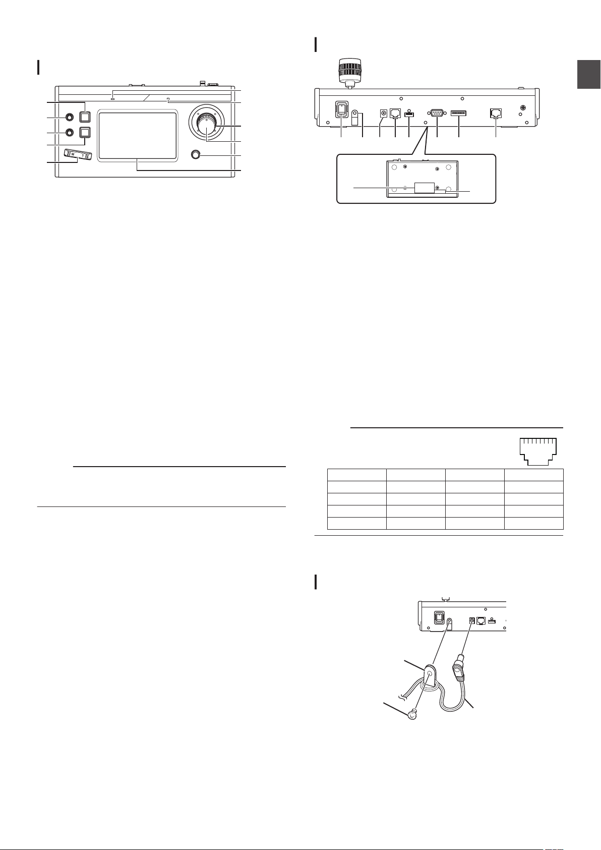
Name of Parts
A
B
C
D
E
F
G
I
H
J
K
A B C D E F G
I
H
J
12345678
Wire Clamp
(supplied)
Screw (M3)
(supplied)
AC adapter
(supplied)
Front Panel
.
USER1 button
A
For configuring the assigned features.
F1 knob
B
For adjusting the assigned features.
F2 knob
C
For adjusting the assigned features.
USER2 button
D
For configuring the assigned features.
Zoom lever
E
For performing the zoom operation of the remote camera.
ALARM lamp
F
Red
POWER lamp
G
Green : Lights up while the power is turned on.
Control lever
H
For operating pan/tilt of the remote camera.
F3 knob
I
For adjusting the assigned features.
F4 knob
J
For adjusting the assigned features.
Operation panel
K
Used as a touch panel.
Memo :
For details on how to assign a function to a button or knob,
0
please refer to the following.
(A P9 “Changing an Assigned Function”)
: Lights up when the alarm is activated.
Rear Panel
.
Power switch
A
For turning the power on or off.
Wire Clamp
B
For preventing the AC adapter cable from falling out.
DC 12V terminal
C
For connecting the supplied AC adapter.
LAN terminal
D
For connecting a LAN cable.
SERVICE terminal
E
For use during servicing.
TALLY terminal
F
Used for TALLY connection.
SETTING switch
G
H
Memo :
0
: For switching TALLY IN and OUT.
1 to 4
5 to 8 : Used for servicing only.
SERIAL terminal
For connecting a serial cable.
The specifications of the terminals are as follows.
Pin No. Signal Pin No. Signal
1 TX+ 5 NC
2 TX- 6 RX3 RX+ 7 GND
4 NC 8 GND
Getting Started
Rating label
I
MAC address label
J
Installing the Wire Clamp
.
Name of Parts
5
Page 6
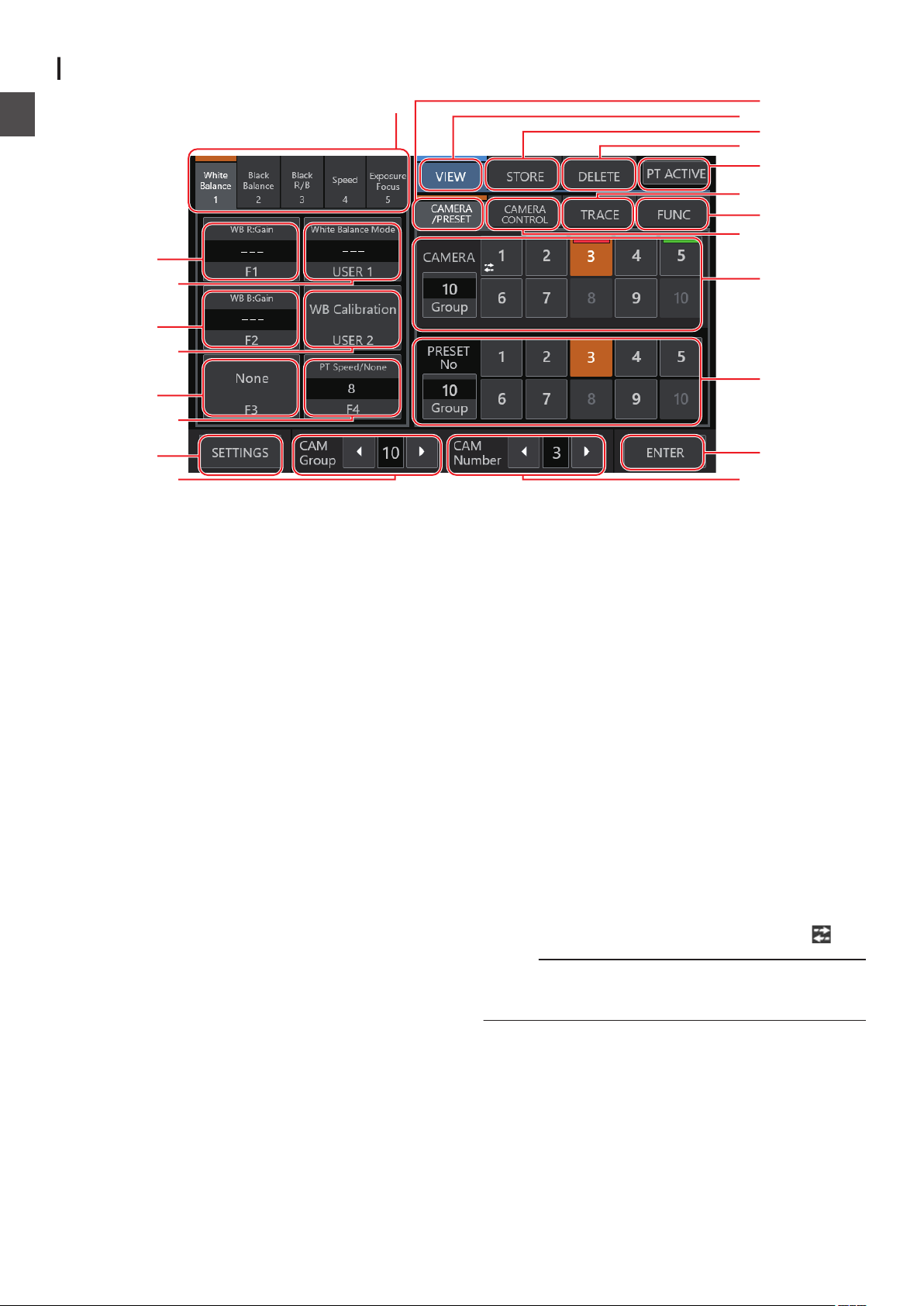
Camera Operation Screen
Q
R
O
K
P
N
U
T
C
B
E
D
G
F
H
M
L
S
JI
A
Getting Started
.
Function Group Button
A
Assigns a combination of the preconfigured functions as a
function group to a button or knob.
(A P10 “Adjusting Using Function Group Buttons”)
White Balance
0
Black Balance
0
Black R/B
0
Speed
0
Exposure/Focus
0
[F1]
B
The function assigned to the F1 knob can be configured.
The default function assigned is
[USER1]
C
The function assigned to the USER1 button can be
configured.
The default function assigned is “One Shot AF”.
[F2]
D
The function assigned to the F2 knob can be configured.
The default function assigned is “Iris”.
[USER2]
E
The function assigned to the USER2 button can be
configured.
The default function assigned is “Shooting Mode”.
[F3]
F
The function assigned to the F3 lever can be configured.
The default function assigned is
[F4]
G
The function assigned to F4 knob can be configured.
The default function assigned is “PT Speed/None”.
[SETTINGS]
H
Tap the button to display the SETTINGS screen.
“Focus”.
“None”.
CAM Group]
[
I
The camera group can be altered using
[CAM Number]
J
The camera number can be altered using the left/right
buttons.
[ENTER]
K
For use in the [STORE] mode and [DELETE] mode. Can be
used to confirm and delete the preset number.
[Preset No./Preset Group] button
L
A preset number or preset group can be selected.
To change the preset group, tap the [Group] button. While
the button is lit, tap one of the Preset Group buttons (1 to 10)
to change the preset group. Tap the [Group] button again.
When the light of the button goes off, the preset number can
be changed.
[Camera No./Camera Group] button
M
A camera number or camera group can be selected.
To change the camera group, tap the [Group] button. While
the button is lit, tap one of the Camera Group buttons (1 to
10) to change the camera group. Tap the [Group] button
again. When the light of the button goes off, the camera
number can be changed.
Tally light status
PGM : Red
PST : Green
Cameras that are disconnected are indicated by a
Memo :
Up to 10 cameras can be configured to one camera group.
0
Up to 10 camera groups can be registered and a total of up
0
to 100 cameras can be configured.
the left/right buttons.
icon.
6
Name of Parts
Page 7
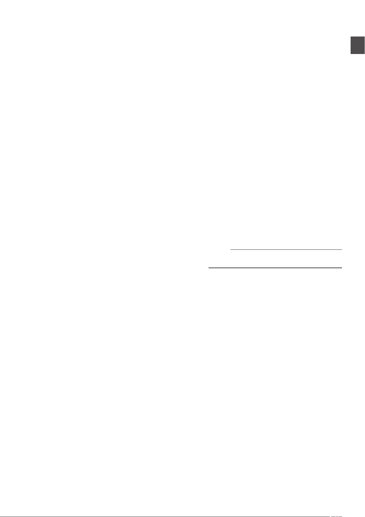
[CAMERA CONTROL]
N
For controlling the currently selected camera.
[FUNC]
O
For changing the settings of the currently selected camera.
[TRACE]
P
For recording the camera operations of the currently selected
camera to replicate the operations at a later time.
[PT ACTIVE]
Q
Tap the button to switch [PT ACTIVE] on and off. Switching
to off disables the pan/tilt operation by the control lever.
[DELETE]
R
Tap the button to enter [DELETE] mode.
[STORE]
S
Tap the button to enter [STORE] mode.
[VIEW]
T
Tap the button to enter [VIEW] mode.
[CAMERA/PRESET]
U
For selecting a camera number or preset number.
Preparations
Set the power switch to
1
The power is turned on and the POWER lamp lights up.
0
The start screen is displayed on the operation panel.
0
The ALARM lamp lights up at the same
this unit cannot be operated.
The start screen disappears after about 10 seconds and
0
the home screen is displayed.
Configure the settings of this unit.
2
Set the IP address of this unit as follows.
0
Select [SETTINGS] on the home screen of the
A
operation panel.
If the home screen does not appear, select
0
[HOME] to display the home screen.
Select [Network].
B
Select [CONTROLLER].
C
The IP address setting screen appears.
0
Enter the IP address and tap
D
Configure the camera settings.
3
Configure the camera to be operated as follows.
0
Select [SETTINGS] on the home screen of the
A
operation panel.
If the home screen does not appear, select
0
[HOME] to display the home screen.
Select [Network].
B
Select [CAMERA REGISTRATION].
C
Perform registration according to the camera to be
D
connected.
IP camera: Select
0
Serial camera: Select [Serial Activate 1]
0
Activate 100
Memo :
For details on the settings, please refer to
0
Network Settings” (A P 16).
“On”.
time. During which,
[ENTER].
[AUTO] or [Manual]
]
Getting Started
or [Serial
“Camera
To add or change the camera to be
0
above procedures again.
operated, perform the
Name of Parts
7
Page 8
Selecting and Operating a
Operating a Camera
Camera
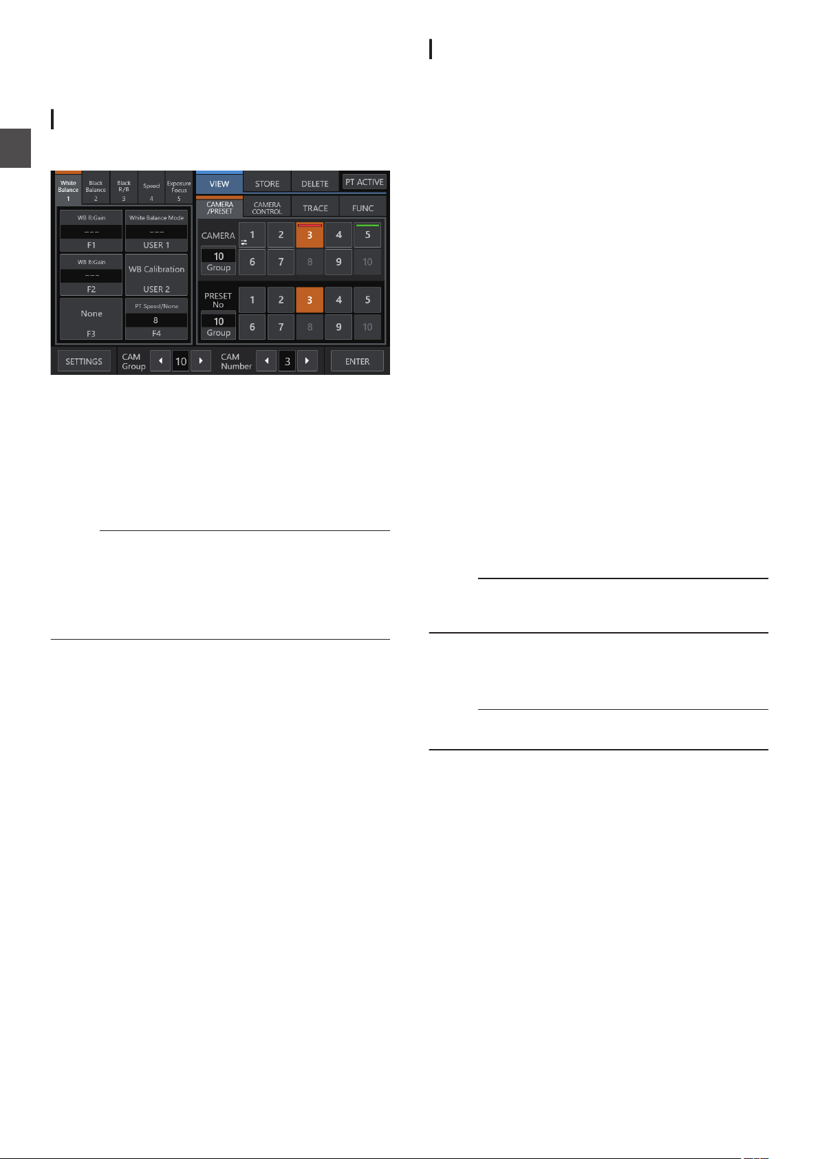
Selecting a Camera
Follow the steps below to specify a camera number and select
a camera to operate.
Operation
.
Display the home screen.
1
If the home screen does not appear, tap the [HOME] button
on the screen.
Tap the left/right buttons of [CAM Group] at the
2
bottom of the operation panel to select a camera
group.
Tap the left/right buttons of [
3
bottom of the operation panel to select a camera
number.
Memo :
[Camera Number/Camera Group] under the [CAMERA/
0
PRESET] tab can also be used to select a camera using the
following steps.
0
Tap [Group] to light up the button, followed by selecting a
group number.
0
Tap the [Group] button again to turn off the button’s light,
followed by tapping a camera number.
CAM Number] at the
Operating the PTZ (pan/ tilt/ zoom)
Select a camera to operate.
1
(A P8
“Selecting a Camera”)
Tilt the
2
control lever
toward
the
direction
you
the camera to move (pan/ tilt operation).
Tilt the lever to the left and right
0
and tilt it up and down to move vertically (tilt).
The speed of the pan/tilt operation can be adjusted using
0
the F1/F2/F4 knobs.
(A P9 “Changing an Assigned Function”)
The movement speed changes depending on the tilt
0
of the lever.
Operate the zoom lever to adjust the size of the
3
to move horizontally (pan)
field of view (zoom operation).
Press the T-end of the lever to magnify the subject
0
(Telephoto) and press the W-end to make the subject
appear smaller (Wide-angle).
The zoom speed changes according to the extent the
0
zoom lever is being pushed.
Zoom operation can also be performed by assigning the
0
F3 knob with the “ZOOM” function.
(A P9 “Changing an Assigned Function”)
The zoom movement speed changes depending on the
0
angle of rotation of the lever.
Performing focus operation
Set the focus mode to
1
Assign the USER1 or USER2 button with “Focus Mode”,
followed by tapping the button to switch to MF.
P9 “Changing an Assigned Function”)
(A
Turn the F1 knob.
2
Turn counterclockwise:
Turn clockwise : Focus on distant objects.
Memo :
The F2, F3 or F4 knob can also be assigned with the focusing
0
function.
(A P9 “Changing an Assigned Function”)
“MF”.
Focus on near objects.
want
angle
One-Shot AF
Tapping the F4 knob performs focusing automatically. The focus
mode switches to MF.
Memo :
The F4 knob needs to be assigned with “Focus/One Shot
0
AF”.
Selecting and Operating a Camera
8
Page 9
Changing an Assigned Function
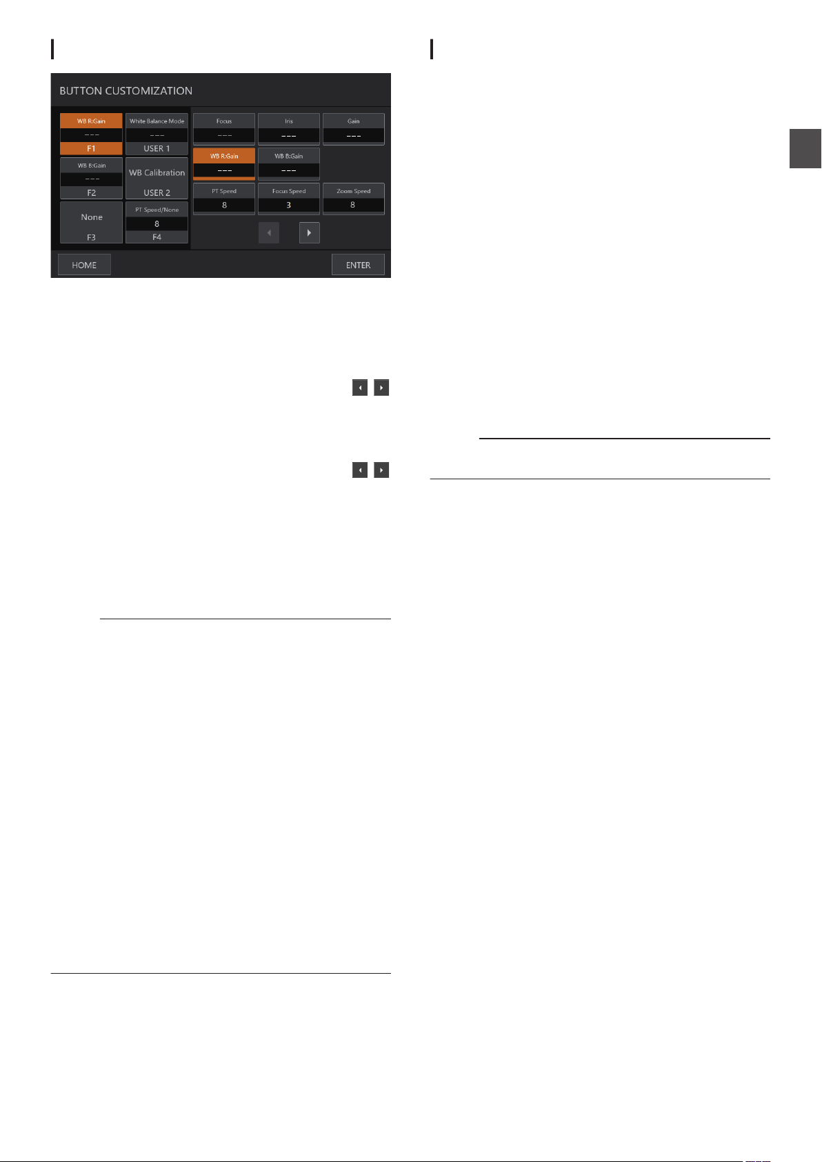
.
Functions assigned to a knob or button can be changed.
The following describes the steps to assign the F1 knob with
“Focus” and the USER1 button with “Focus Mode”.
Select [F1] on the operation panel.
1
Select “Focus”
2
on the right side of the screen.
the function you want to select
If
to jump to the next page.
Select [USER1] on the operation panel.
3
Select “Focus Mode
4
area on the right side of the screen.
If the function you want to
to jump to the next page.
You can switch between “AF” and “MF” focus using the
USER1 button. Setting focus to “MF” allows you
focus using the F1 knob.
Tap the
5
Tapping the [ENTER] button confirms the selected setting
and
button cancels the selected setting and returns the display to
home screen.
[ENTER
returns
Memo :
The functions that can be assigned to each button or knob
0
are as follows. Some functions might not be configurable
depending on the camera to be connected, and the menus
cannot be operated in this case.
F1/F2
o
Focus, Iris, Gain, WB R:Gain, WB B:Gain, PT
Speed, Zoom Speed, Shutter Speed, Clear Scan,
Slow(Second), AGC Limit, AE Shift, Color Temperature, R
Gain, B Gain, Sharpness:Level, Sharpness:Limit, Noise
Reduction, Knee:Slope, Knee:Point, Knee:Saturation,
Master Pedestal, Master Black R, Master Black B, Black
Gamma Level, Black Gamma Range, Black Gamma Point,
Color Matrix:Gain, Color Matrix:Phase, Color Matrix:R-G,
Color Matrix:G-R, Color Matrix:B-R, Color Matrix:R-B,
Color Matrix:G-B, Color Matrix:B-G
F3
o
Zoom, Iris, Focus, None
USER1/USER2
o
Shooting Mode, Iris, Shutter Mode, Gain, ND Filter, Metering
Mode, None, One Shot AF, Focus Mode, White Balance
Mode, WB Calibration, Rec, Preset Color Settings, Gamma,
Color Space, Color Matrix, HLG Color, Noise Reduction,
KneeーActivate, Knee-Automatic
F4
o
Focus/One Shot AF, PT Speed/None
from the function selection area
is not displayed, tap
” from the function selection
select is not displayed, tap
] button.
display to home screen. Tapping
the
to adjust the
the [HOME]
Speed, Focus
Selecting a Preset
What is preset?
o
This system allows multiple shooting positions and settings
to be registered for one camera. Such a registered shooting
position or setting is referred to as a “preset”. Up to 100
presets can be registered for a remote camera. This product
manages the presets by dividing them into 10 groups. For
example, the first preset of the camera corresponds to the
first preset of Group 1 on this product, while the 11th preset
corresponds to the first preset of Group 2.
Selecting a Preset
Follow the steps below to specify a preset number for retrieving
the corresponding camera shooting position or setting.
Select a camera to operate.
1
(A P8 “Selecting a Camera”)
Tap the [
2
Select the
3
Tap
4
VIEW] button on the operation panel.
[CAMERA/PRESET] tab.
[
Group] of [Preset No./Preset Group] to light
up the button, followed by selecting a group
number.
Tap the
5
button’s light, followed by tapping a preset
Group] button again to turn off the
[
number.
registered shooting position
The
or setting is being retrieved.
Memo :
The number of the button is displayed in white if a preset
0
number is registered to it.
Registering a Preset
Select a camera to operate.
1
(A P8 “Selecting a Camera”)
Tap the [STORE] button on the operation panel.
2
Select the
3
Tap
4
[CAMERA/PRESET]
[
Group] of [Preset No./Preset Group] to light
tab.
up the button, followed by selecting a group
number.
Tap the
5
Group] button again to turn off the
[
button’s light, followed by tapping a preset
number.
Tap the
6
The current shooting position or setting is registered to the
preset number of the selected preset group.
ENTER] button.
[
Deleting a Registered Preset
Select a camera to operate.
1
A
(
P8 “Selecting a Camera”)
Tap the [DELETE
2
Select the [CAMERA/PRESET]
3
Tap [
4
Group
up the button, followed by selecting a group
number.
Tap the [
5
Group] button again to turn off the
button’s light, followed by tapping a preset
number.
Tap the [
6
The
the preset group is deleted.
ENTER] button.
registration information of the
] button on the operation panel.
tab.
] of [Preset No./Preset Group] to light
selected preset number of
Operation
Selecting and Operating a Camera
9
Page 10
Adjusting the Camera Functions
Adjusting Using Function Group Buttons
Tap the Function Group button.
1
Operation
Functions with a preconfigured combination are assigned to
the buttons and knobs.
For example, by tapping the [White Balance] button, the
[USER1] button can be used to toggle the white balance
setting between “AWB”/“Daylight”/“Tungsten”/“Kelv”/
“Manual”/“SetA”/“SetB”.
Tapping
function group selection.
Function Group Button Default Setting
White Balance F1: WB R:Gain, F2: WB
Black Balance F1: Master Pedestal, F2: Black
Black R/B F1:
Speed F1: Focus Speed, F2: Zoom
Exposure/Focus F1: Focus, F2: Iris, F3: None,
To change the function, tap the corresponding
2
the selected Function Group button again clears the
B:Gain, F3: None, F4: PT
Speed/None, USER1: White
Balance Mode, USER2: WB
Calibration
Gamma Level, F3: None,
None,
User1:
PT Speed/None
Master
Black B, F3: None, User1:
None, User2: None, F4: PT
Speed/None
Speed, F3: None, User1:
None, User2: None, F4: PT
Speed/None
User1: One Shot AF, User2:
Shooting
None
User2: None,
Black
Mode, F4: PT
button on the operation panel to select a
followed by tapping the [ENTER] button.
Adjusting Using CAMERA CONTROL
Select a camera to operate.
1
(A
P8 “Selecting a Camera”)
Tap the [CAMERA CONTROL
2
Adjust the Functions.
3
The adjustable items are as follows. Note that some items
might not be adjustable depending on the camera that is
connected.
[White Balance], [Gain], [Shutter
[Focus] (AUTO
ON/OFF), [ND], [Sharpness]
] tab.
], [Iris] (AUTO ON/OFF),
F2: Master
R,
function,
F4:
Speed/
Adjusting Using FUNC
Select a camera to operate.
1
(A P8 “Selecting a Camera”)
Tap the [FUNC] tab.
2
Adjust the Functions.
3
If the function you want
to jump to the next page.
The adjustable items are as follows. Some menus
not be adjustable depending on the camera that is
connected.
Digital Zoom, D.Tele-Converter, Soft Zoom Control, PT
Acceleration, Image Stabilizer, Focus limit, AF Mode, Face
Detection AF, AF Speed, AF Response, AWB Response, AE
Response, ND Filter Mode, Auto Slow Shutter, Flicker
Reduction, IR Cut Filter, Wiper, Washer, AUX1, AUX2,
AUX3, AUX4
to select is not displayed, tap
items may
Tracing
Recording Camera Operations (Tracing)
Select a camera to operate.
1
(A P8 “Selecting a Camera”)
Tap the [STORE] button on the operation panel.
2
Tap the [
3
Tap the [
4
camera.
Tap the [
5
operations.
Memo :
This function is only supported on IP cameras.
0
Tapping the [Cancel] button while recording is in progress
0
erases the trace record.
Playing Camera Operations (Tracing)
Select a camera to operate.
1
(A
Tap the [VIEW
2
Tap the [
3
Tap the [
4
position to start tracing.
Tap
5
Memo :
Tapping the [Cancel] button stops the tracing process.
0
Selecting the number in the [DELETE] tab and tapping
0
[ENTER] erases the recorded trace.
TRACE] tab and select a number.
Start Rec] button and operate the
Stop Rec] button to register the
P8 “Selecting a Camera”)
] button on the operation panel.
TRACE] tab and select a number.
Prepare Trace] button to shift to the
Execute Trace] button
the [
to execute tracing.
Adjusting the Camera Functions
10
Page 11

Setup Flow
Basic Operations of Menu
When setting up the system for the first time, or when new
cameras are added, set up in the manner as follows.
Be sure to perform an operation check after the setup.
IP address settings
1
Configure the IP address of the connected device according
to the system configuration.
(A P16 “Network Settings”)
Camera setup
2
Set up the connected camera.
(A P15 “Camera Settings Menu”)
Remote control settings
3
For configuring the functions to be assigned to the buttons
and knobs of this unit.
(A P9 “Changing an Assigned Function”)
Screen
[
Tap the
1
The settings menu appears.
Select the item to be configured.
2
Settings Menu
Video
o
Allows you to switch the video outputs of the connected
cameras on or off.
(A P15 “Switching the Camera Video Output On/Off”)
MENU Control
o
Allows you to display and operate the settings menu of the
selected camera.
(A P15 “Camera Settings Menu”)
Function
o
Allows you to configure the settings for this unit.
Touch Screen Volume
0
Allows you to configure the operation sound
panel.
Brightness
0
Allows you to configure the brightness of the operation panel.
Power Save
0
Allows you to configure the duration of time before this unit
enters into power save mode.
Tapping the operation panel while in the Power Save mode
exits the mode.
Power save mode is disabled while the settings
is displayed.
Default Setting
0
Allows you to restore the default settings of this unit.
Tapping the button changes the button color. Tap the
[ENTER] button in this condition and then turn off the power
to restore the default settings.
Default Setting User
0
Initializes the function that is assigned to a button.
Tapping the button changes the button color. Tapping the
[ENTER] button in this state executes initialization and
displays “Completed”. Tap the [Close] button to
configuration.
Setting Data<->USB
0
Allows you to write the settings of this unit to a USB drive and
vice versa.
Connect the USB drive to the SERVICE terminal on the rear
panel of this unit.
Memo :
Format the USB drive with FAT32/16 in advance. This unit
0
does not support formatting.
Network
o
Allows you to configure settings related to the network.
(A P16 “Network Settings on This Controller”)
Touch Screen
o
Allows you to calibrate the operation panel.
Tapping the [Touch Screen] button displays the adjustment
screen. Operate according to the on-screen instructions.
SETTINGS] button on the home screen.
of the operation
menu screen
complete the
Settings
Setup Flow
11
Page 12
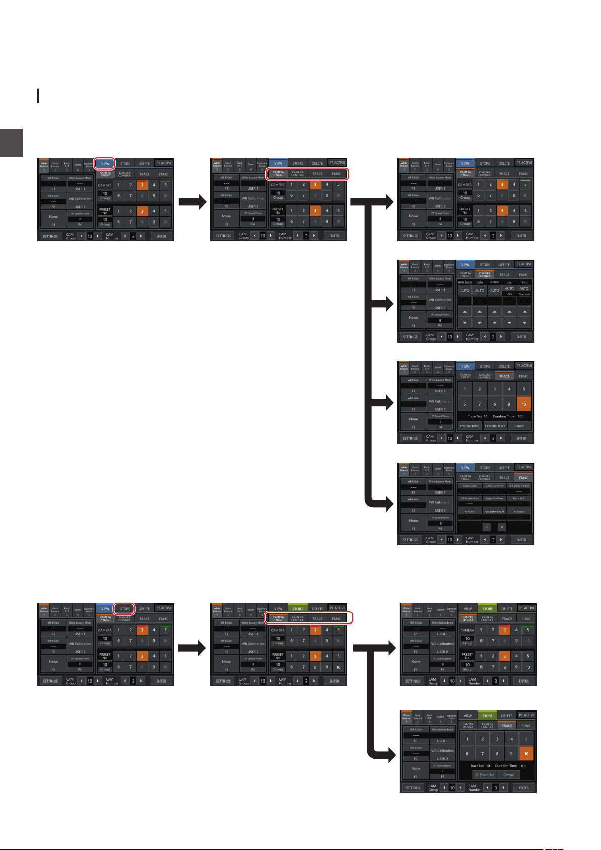
Menu Screen Flow
Home Screen CAMERA/PRESET
Screen
VIEW
Screen
TRACE
Screen
CAMERA CONTROL
Screen
FUNC
Screen
Home Screen CAMERA/PRESET
Screen
STORE
Screen
TRACE
Screen
The menu screens consist of normal menu screen
o
below.
and settings menu screen. The flow of the each screen is as shown in the figures
Normal Menu Screen
VIEW Screen
This screen is used for selecting a camera, selecting a camera preset, operating a camera and performing tracing.
.
Settings
STORE Screen
This screen is used for registering a camera preset or tracing.
.
Menu Screen Flow
12
Page 13
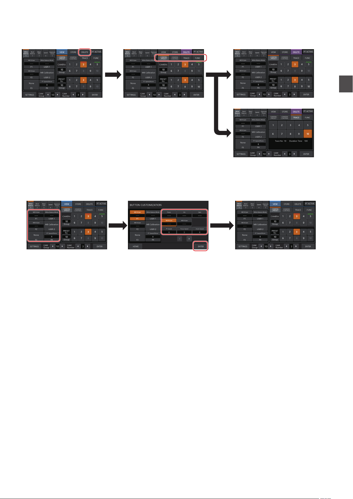
DELETE Screen
Home Screen CAMERA/PRESET
Screen
DELETE
Screen
TRACE
Screen
Home Screen Home Screen
BUTTON CUSTOMIZATION
Screen (*)
* You can adjust the function that
is highlighted without tapping
[ENTER] while the screen is displayed.
This screen is used for deleting a camera preset or tracing.
BUTTON CUSTOMIZATION Screen
For assigning functions to the buttons and knobs of this unit.
.
Settings
.
Menu Screen Flow
13
Page 14
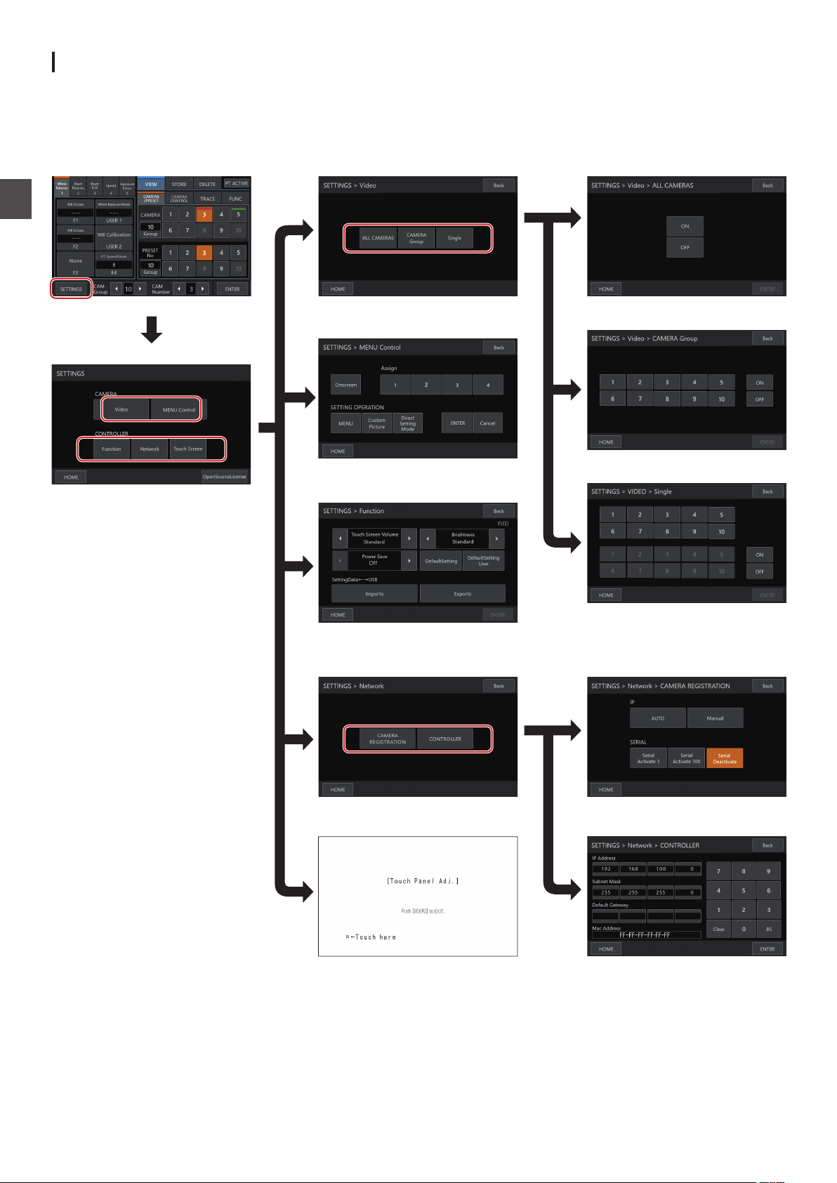
Settings Menu Screen
Home Screen
SETTINGS Screen
Video Screen ALL CAMERAS Screen
CAMERA Group Screen
Network Screen CAMERA REGISTRATION Screen
CONTROLLER Screen
MENU Control Screen
Single Screen
Function Screen
Touch Screen Screen
SETTINGS Screen
For configuring the settings of this unit. Tap the [Back] button at the top right corner
the [HOME] button at the bottom left corner of the screen to return to the home screen.
(A P11 “Settings Menu”)
.
Settings
of the screen to return to the previous screen. Tap
Menu Screen Flow
14
Page 15
System Setup
Switching
Toggles the video output of the camera between on and off. For
some cameras, it is used to switch the camera between the
power-on and standby states.
Setting the video outputs of all cameras on/off
Display the home screen.
1
If the home screen does not appear, tap the [HOME] button
on the screen.
Tap the
2
The SETTINGS screen appears.
Tap the [Video] button.
3
Tap the
4
Tap the
5
0
0
Tap the [ENTER] button to confirm the setting.
6
[SETTINGS] button.
[ALL CAMERAS]
[
Tapping the button changes the button color.
Tap the [ON] button to set the video output of the camera
to on.
Tap the [OFF] button to set
to off.
Camera Video
the
button.
ON] or [OFF] button.
the video output of the camera
Output
On/Off
Tap the number button corresponding to the
6
number of the camera to be configured.
Multiple cameras within the same group can be selected.
0
Numbers that do not correspond to any of the existing
0
cameras are indicated in white.
Tap the [
7
Tapping the button changes the button color.
0
Tap the [ON] button to set the video output of the camera
0
to on.
Tap the [OFF] button to set the
to off.
Tap the [ENTER
8
ON] or [OFF]
button.
video output of the camera
] button to confirm the setting.
Memo :
[ALL CAMERAS] can be configured to “ON”/“OFF” only for
0
cameras within the same network.
To control the Video output of a camera that is not within the
0
same network, use CAMERA Group or Single.
When the video output of a camera is turned off, you will not
0
be able to control the camera.
Camera Settings Menu
Settings
Setting
the
video
outputs
camera
of
groups on/
off
Display the home screen.
1
If the home screen does not appear, tap the [HOME] button
on the screen.
Tap the [SETTINGS
2
The SETTINGS screen appears.
Tap the [Video] button.
3
Tap the [CAMERA Group] button.
4
Tap the number button corresponding to the
5
] button.
number of the camera group to be configured.
Multiple camera groups can be selected.
0
The digit of the number with non-existent camera within
0
the camera group is displayed in white.
Tap the [ON] or [OFF] button.
6
Tapping the button changes the button color.
0
Tap the [ON] button to set the video output of the camera
0
to on.
Tap the
to off.
Tap the [ENTER] button to confirm the setting.
7
[OFF] button to set
the video output of the camera
Setting the video output of individual camera
on/off
Display the home screen.
1
If the home screen does not appear, tap the [HOME] button
on the screen.
Tap the [
2
The SETTINGS screen appears.
Tap the [
3
Tap the [
4
Tap the number button corresponding to the
5
number of the camera group to be configured.
The digit of the number with non-existent camera within the
camera group is displayed in white.
SETTINGS
] button.
Video] button.
Single] button.
Making changes to the settings menu of the
camera
Tap the [SETTINGS] button on the home
1
the operation panel.
The SETTINGS screen appears.
0
If the home screen does not appear, select [HOME] to
0
display the home screen.
Tap the [MENU Control] button on the SETTINGS
2
screen.
Make
3
Onscreen Toggles the on-screen display between on
MENU Toggles the menu display between on and
Custom Picture Toggles the customized picture menu
Direct Setting
Mode
Assign 1 to 4 Executes the function assigned to the
ENTER Confirms an operation
Cancel Cancels an operation
4
changes to the
You can use the operation panel buttons to select a
0
function and use the control lever and buttons to change
the setting.
Buttons Functions
and off
off when the on-screen display is on
between on and off when the on-screen
display is on
For selecting a Camera Direct setting when
the on-screen display is on
Assign button
Tap the [HOME] button.
After changing the settings, tap the [HOME] button to
0
return to the home screen.
settings menu of the
Memo :
Some cameras might not allow operation of the menu.
0
For details on making changes to the settings menu of the
0
camera, please refer to the User Manual of the camera.
When removing the camera from the network, delete the
0
camera registration as well.
screen of
camera.
System Setup
15
Page 16
Network Settings
Camera Network Settings
Settings
.
Display the home screen.
1
If the home screen does not appear, tap the [HOME] button
on the screen.
Tap the [SETTINGS
2
The SETTINGS screen appears.
Tap the [Network] button.
3
Tap the [CAMERA REGISTRATION] button.
4
Tap
5
Memo :
0
0
0
0
the button corresponding to the camera to
connected.
IP Camera [AUTO]
o
Tapping the [AUTO] button displays a message.
Tapping the [ENTER]
cameras that can be operated without user authentication
and displays the “Completed” message. Tap the [Close]
button to complete the configuration.
IP Camera [Manual]
o
Tapping the [Manual] button displays the manual settings
screen for IP address.
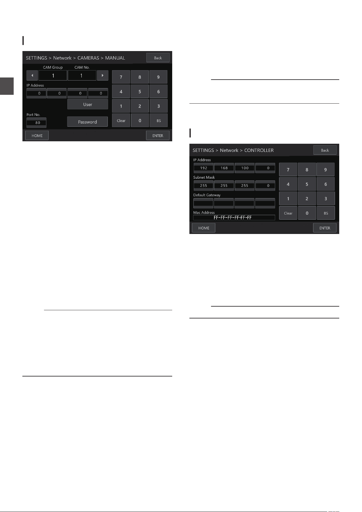
Tap the left/right buttons to select a registered [CAM
0
Group] and [CAM No.].
Enter the IP address using the numeric keypad.
0
Configure [Port No.], [User
0
Tap the [ENTER] button to confirm the entered values.
0
Configure all the cameras to be registered using
0
procedures.
This is a function to register the IP address of the camera to
this unit. The IP address of the camera unit cannot be
changed even when performing manual registration by
selecting [Manual].
Use the same [Port No.], [User] and
on the connected camera.
Configuring the IP address to “0.0.0.0” deletes the registration
of that camera.
Numbers corresponding to a serial camera cannot be
registered.
] button.
button automatically registers up
] and [Password].
the same
[Password] as configured
be
to 10
[Serial Activate 1] and [Serial Activate 100] Serial
o
Cameras
Serial cameras can be registered to <1-1> or <10-10>.
0
(<Camera Group No.-Camera No.>)
Tap [Serial Activate 1] to register to <1-1> and tap [Serial
0
Activate 100] to register to <10-10>.
“Completed” appears when connection is established.
0
Upon tapping the [Close] button, configuration is complete
and the button color changes.
Memo :
Serial cameras cannot be registered to buttons
0
corresponding to a number that is registered with an IP
camera.
[Serial Deactivate] Serial Camera Deactivation
o
To deactivate the use of a serial camera, select [Serial
Deactivate].
Network Settings on This Controller
.
Display the home screen.
1
If the home screen does not appear, tap the [HOME] button
on the screen.
Tap the [SETTINGS] button.
2
The SETTINGS screen appears.
Tap the [Network] button.
3
Tap the [CONTROLLER] button.
4
The network settings screen of this unit appears.
Enter each item and tap the [ENTER] button.
5
Memo :
The default IP address of this unit is 192.168.100.0.
0
Network Settings
16
Page 17
Tally Setup
1ON2345678
1
6
5
9
1ON2345678
1ON2345678
1ON2345678
1ON2345678
RC-IP100
LED
TALLY OUT
(Maximum current
50 mA)
(Maximum voltage 24 V)
GND
+5 V
TALLY IN
S
D
G
RC-IP100
GND
Tally Control Interface
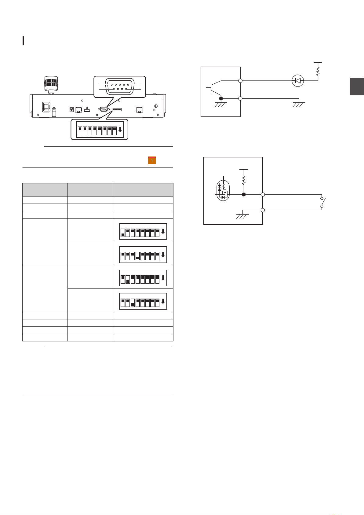
Configure the pin 4 and pin 5 functions of the tally terminal using
the SETTING switch on the rear panel.
Other than pin 4 and pin 5, the remaining pin functions cannot
be changed.
.
Memo :
If a camera has been selected to receive tally signals, the
0
button corresponding to the camera appears like .
Configuration method
Tally terminal pin
number
1 INPUT-1 2 INPUT-2 3 INPUT-3 4 INPUT-4
Function SETTING switch
Connection example for TALLY OUT
Please ensure the following conditions are met.
Voltage
Current :
: Maximum DC 24 V
Maximum 50 mA
.
Connection example for TALLY IN
Set up the contact input.
.
Settings
.
OUTPUT-5
.
5 INPUT-5
.
OUTPUT-4
.
6 GND 7 OUTPUT-1 8 OUTPUT-2 9 OUTPUT-3 -
Memo :
The tally input or tally output supports camera number 1 to 5
0
of camera group 1. To use the tally input or tally output, assign
the cameras to these numbers. For details on the tally input
and tally output, refer to the “Function” column of
"Configuration method".
Inserting and removing of the tally terminal should be
0
performed while the power is turned off.
Tally Setup
17
Page 18
Troubleshooting
RC-IP100
RS-422 cable
LAN cable
Serial camera IP camera IP camera
HUB
Problem Symptom Action
Power does
not turn on.
No response even
after tapping the
operation panel on
the unit.
Turn off the power switch at
the back of the unit and
power on again. If it still
does not start up, stop using
the unit, disconnect the
power cord from the power
outlet and consult a dealer
or our service center.
Third-party Software
Others
This product includes third-party software modules. For the
licensing terms of the respective modules, please refer to
[HOME]>[SETTINGS]>[Open Source License].
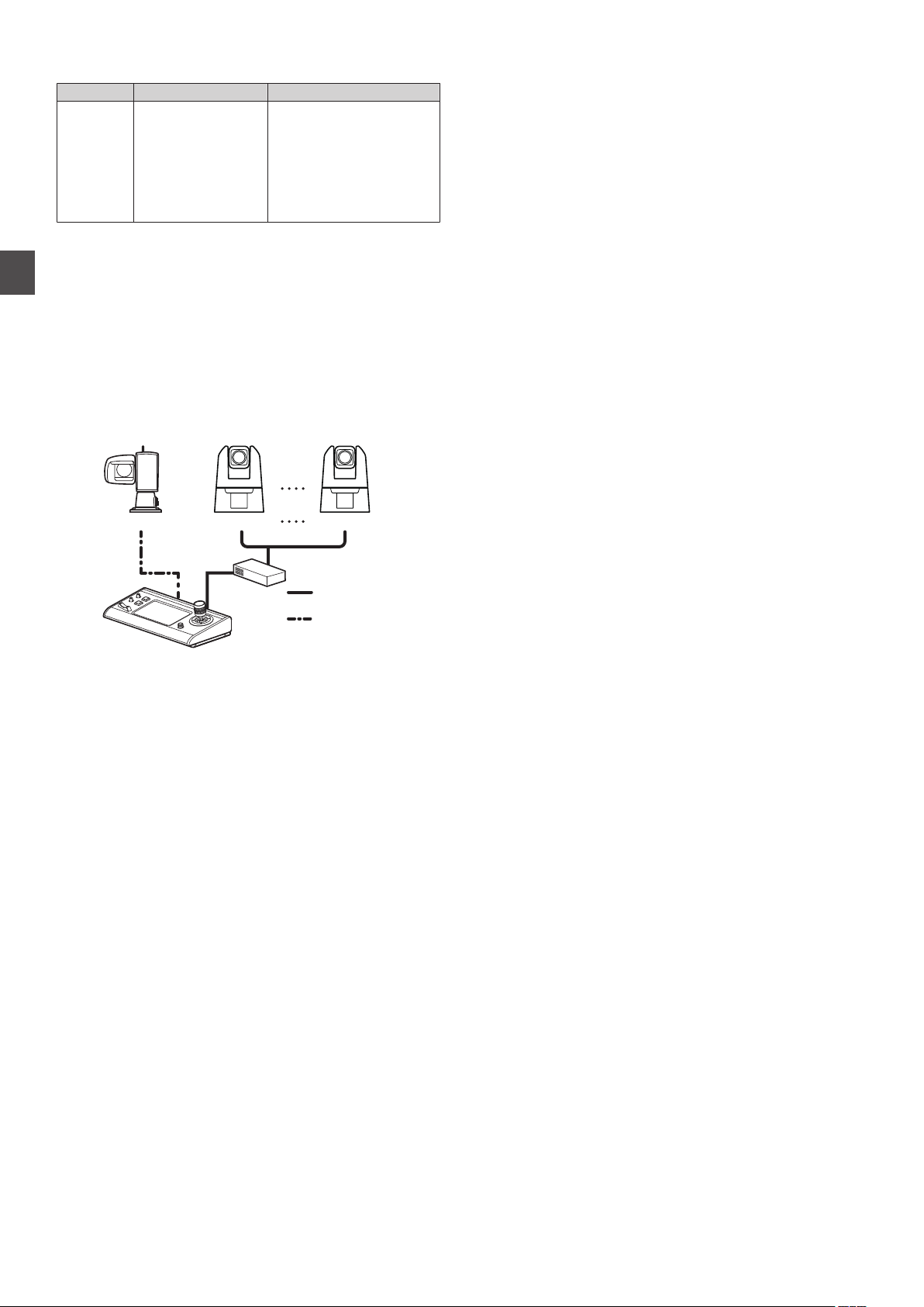
Connection Diagram
.
* Up to 100 cameras can be connected concurrently.
Troubleshooting
18
Page 19
Specifications
350
182
110
60
For
latest information
the
etc.), please visit our website.
General
Item Description
Power DC 12 V
Current consumption 0.6 A
Mass
Surrounding
temperature
Allowable operating
humidity
Terminal Section
Item Description
TALLY terminal D-sub 9-pin
LAN terminal 10BASE-T/100BASE-TX
DC 12V terminal DC jack (for the supplied AC adapter)
SERIAL terminal RS-422
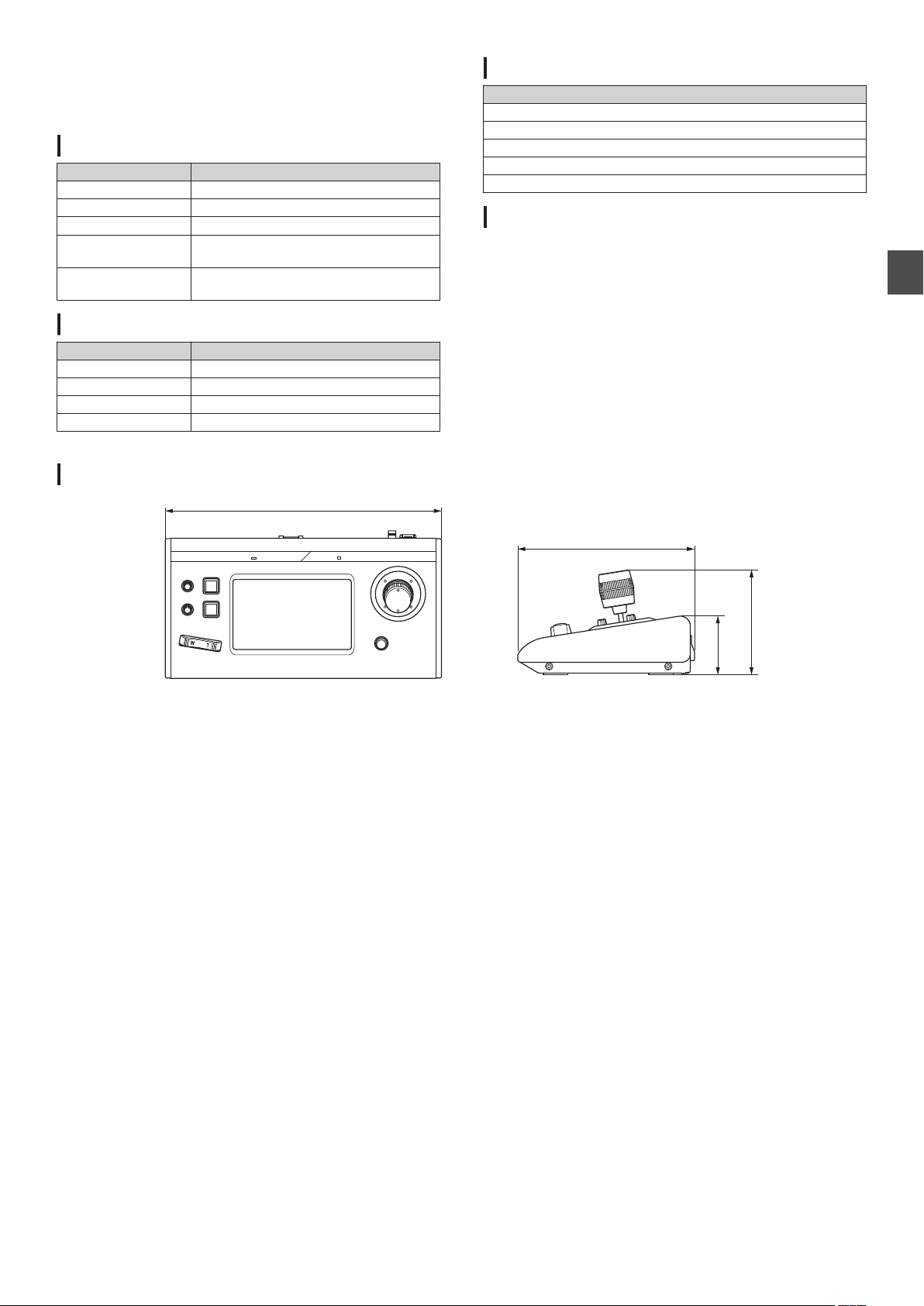
Dimensional Outline Drawing (Unit: mm)
the
on
product
Approx. 2.1 kg
0 °C to 40 °C (32 °F to 104 °F) (operation)
20 %RH to 90 %RH (No condensation)
(firmware,
User Manual,
Accessories
Accessories
Printed Materials
AC Adapter
Power Cord
Wire Clamp
Screw (M3)
Compatible Cameras
Please refer to “About Cameras Compatible to the Remote
Camera Controller RC-IP100” on the website. Please note that
some features might not be usable depending on
use.
the camera in
Others
* The specifications and appearance of this product are subject to changes for further improvement without prior notice.
.
Specifications
19
Page 20
Updated Information
The previous pages covers information in Version 1.00. For
new features/changes in Version 1.01 and later, read the
following.
Version Check and Update
■ Function
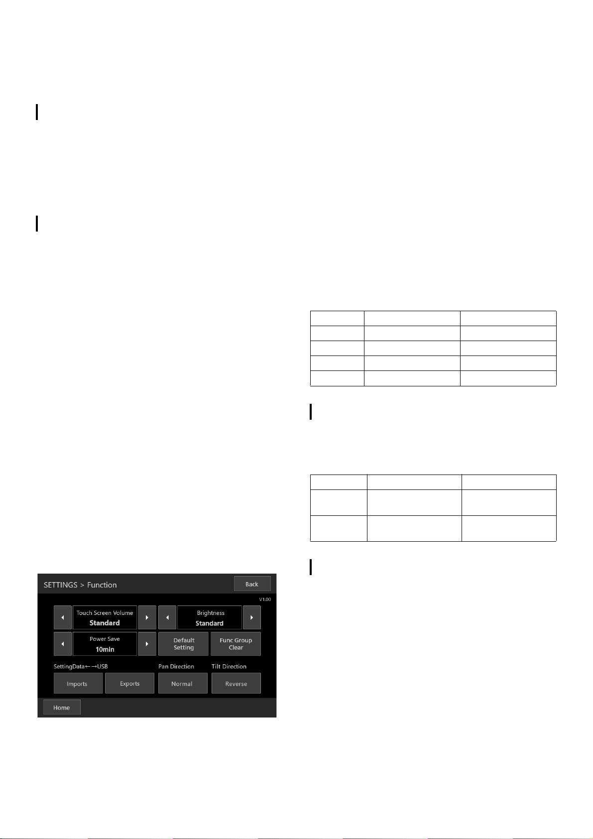
Pan Direction/Tilt Direction
When operating the camera with the control lever, the user
can set the direction in which the camera operates when
the lever is tilted. When [Pan Direction] is set to [Normal],
the camera moves clockwise by tilting the lever to the right.
Also, when [Tilt Direction] is set to [Normal], tilting the lever
toward the user will tilt the camera forward.
To check the version, select [SETTINGS] > [Function] and
check the version information displayed in the upper right
corner of the [Function] screen.
If necessary, download the latest firmware from the website
and update the firmware of this controller.
Refer to the documentation that came with the firmware to
update.
Version 1.01
New features and specification changes are listed below.
■ Method for Calling a Preset
■ Setting the PT Operation Direction
■ Adding Functions that can be Assigned to the Buttons and
Knobs
■ Changes in the Factory Default Settings
Method for Calling a Preset
When calling a preset, it is now possible to specify the speed
level by time or by speed.
■ Calling a Preset
Press the USER1 button to select whether to specify the
speed level by time or by speed in [Speed Mode], turn the
F1 knob to adjust the value, and then call the preset.
(☞ P9 “Selecting a Preset”)
Depending on the relationship between the pan/tilt/zoom
position before the call and the registered pan/tilt/zoom
position, and the [Time (sec.)] setting, it may not operate
within the set time.
■ Stopping a Preset Call
Pressing the USER2 button during preset operation stops
the operation.
Setting the PT Operation Direction
It is now possible to change the direction in which the camera
moves when using the pan or tilt with the control lever.
Adding Functions that can be Assigned to the
Buttons and Knobs
■ Adding Functions
It is now possible to assign the functions relating to the
preset to each button and knob.
F1/F2/F4
Time (sec.)/Speed
USER1/USER2
Speed Mode, Stop
Changes in the Factory Default Settings
The values of the factory default settings were changed as
follows:
(☞ P6 “Camera Operation Screen”)
Before After
[F1] Focus Time (sec.) / Speed
[F2] Iris Zoom Speed
[USER1] One Shot AF Speed Mode
[USER2] Shooting Mode Stop
Version 1.10
New features and specification changes are listed below.
■ Added Adjustable Functions and Changed Item Name in
[FUNC]
Before After
Added - [Enhanced ND Filter]
[Color Bars]
Changed
item name
[IR Cut Filter] [Infrared]
Version 1.20
The new functions and specification changes are as follows.
■ ISO support [F1,F2,USER1,USER2,CAMERA CONTROL]
■ Supports ISO/Gain limit at auto [F1,F2]
■ Supports CC settings for WB [F1,F2]
■ Adding Custom Picture file select [F1,F2]
■ Spatial Filter and Frame Correlation support for NR [F1,F2]
■ Adding functions that can be set in [FUNC]
Gain Boost, Face Detection AE, Eye Detection, AWB Lock,
Shockless WB
■ Adding Shutter [F1,F2]
■ MENU Control button added to the assigned function
[USER1,USER2]
■ Activate can be selected without connecting a serial
camera
■ BUTTON CUSTOMIZATION screen procedure changes
Page 21

ISO support [F1,F2,USER1,USER2,CAMERA
CONTROL]
[Gain] is changed to [ISO/Gain] and ISO can now be adjusted.
Displays the ISO setting status when ISO is used and the Gain
setting status when Gain is used, according to the camera
settings.
Supports ISO/Gain limit at auto [F1,F2]
AGC Limit can now be controlled when using ISO.
Supports CC settings for WB [F1,F2]
Color Compensation [WB CC] for white balance can now be
adjusted.
Adding Custom Picture file select [F1,F2]
Custom picture files can now be selected.
Spatial Filter and Frame Correlation support for
NR [F1,F2]
Spatial Filter and Frame Correlation for noise reduction can
now be set.
Adding functions that can be set in [FUNC]
The following five functions have been added to [FUNC].
■ Gain Boost
■ Face Detection AE
■ Eye Detection
■ AWB Lock
■ Shockless WB
(☞ P10 “Adjusting Using FUNC”)
Adding Shutter [F1,F2]
A new function [Shutter] has been added that allows Shutter
settings to be made independently of Shutter Mode.
Procedure before change Procedure after change
HOMEF1/F2/F3/F4/
USER1/USER2
BUTTON
CUSTOMIZATION
ENTER or HOME
Please waitHOME
HOMEF1/F2/F3/F4/USER1/
USER2
Change Settings?
CancelHOME
or,
HOMEF1/F2/F3/F4/USER1/
USER2
Change Settings?
OK
BUTTON CUSTOMIZATION
[Amendment]
The table in “3 Make changes to the settings menu of the
camera.” on page 15 is amended as follows.
Buttons Features
Onscreen Toggles the on-screen display
between on and off
MENU Toggles the menu display between on
and off
Custom Picture Toggles the customized picture menu
between on and off
Direct Setting Mode Selects a Camera Direct setting
Assign 1 to 4 Executes the function assigned to the
Assign button
ENTER Confirms an operation
Cancel Cancels an operation
MENU Control button added to the assigned
function [USER1,USER2]
When MENU Control is assigned to the USER1 and USER2
buttons, the SETTING screen is omitted and the display shifts
to the MENU Control screen. Also, when “Back” is pressed, it
returns to the HOME screen.
(☞ P15 “Making changes to the settings menu of the camera”)
Activate can be selected without connecting a
serial camera
Serial Activate1 or Serial Activate100 can now be selected
without connecting a serial camera.
(☞ P7 “Configure the camera settings.”)
BUTTON CUSTOMIZATION screen procedure
changes
After pressing the customized buttons (F1/F2/F3/F4/USER1/
USER2), the screen for selecting whether or not to assign a
function (“Change Settings?” screen) is now displayed.
(☞ P9 “Changing an Assigned Function”)
Page 22

Version 1.30
The new functions and specification changes are as follows.
■ Adding functions that can be set in [FUNC]
[Save]
■ Added [Preset Save Item] to assignment functions
[USER1,USER2]
■ [Preset Level] added to [View Option]
[USER1,USER2]
■ PT speed control function linked to the zoom can be
switched On/Off
Adding functions that can be set in [FUNC]
The following function has been added to [FUNC].
■ [Save]
This is enabled only in [STORE] mode. Executing [Save]
allows you to save the camera setting values to the
camera.
(☞ P10 “Adjusting Using FUNC”)
Added [Preset Save Item] to assignment
functions
[USER1,USER2]
When [Preset Save Item] is assigned to [USER1] and
[USER2], you can choose to save presets from the three
options of [All], [PTZF], and [CAM Settings].
[Preset Level] added to [View Option]
[USER1,USER2]
[Preset Level] (movement speed when a preset is registered)
added to [Time] (movement time) and [Speed] (movement
speed) of [View Option] for [USER1] and [USER2].
PT speed control function linked to the zoom
can be switched On/Off
Registering a camera to connect
PT mode (On/Off) has been added to the [SETTING] >
[Network] > [CAMERAS] > [MANUAL] screen (P16).
[On]: The pan/tilt speed is fastest at the Tele end and slowest
at the Wide end.
[Off]: The pan/tilt speed is constant, regardless of the zoom
position.
Page 23

The functions available on this device may differ depending on the camera and connection method.
BIE-7290-004 © CANON INC. 2022
 Loading...