

Page 1
2000 Fire Door-Fan Manual
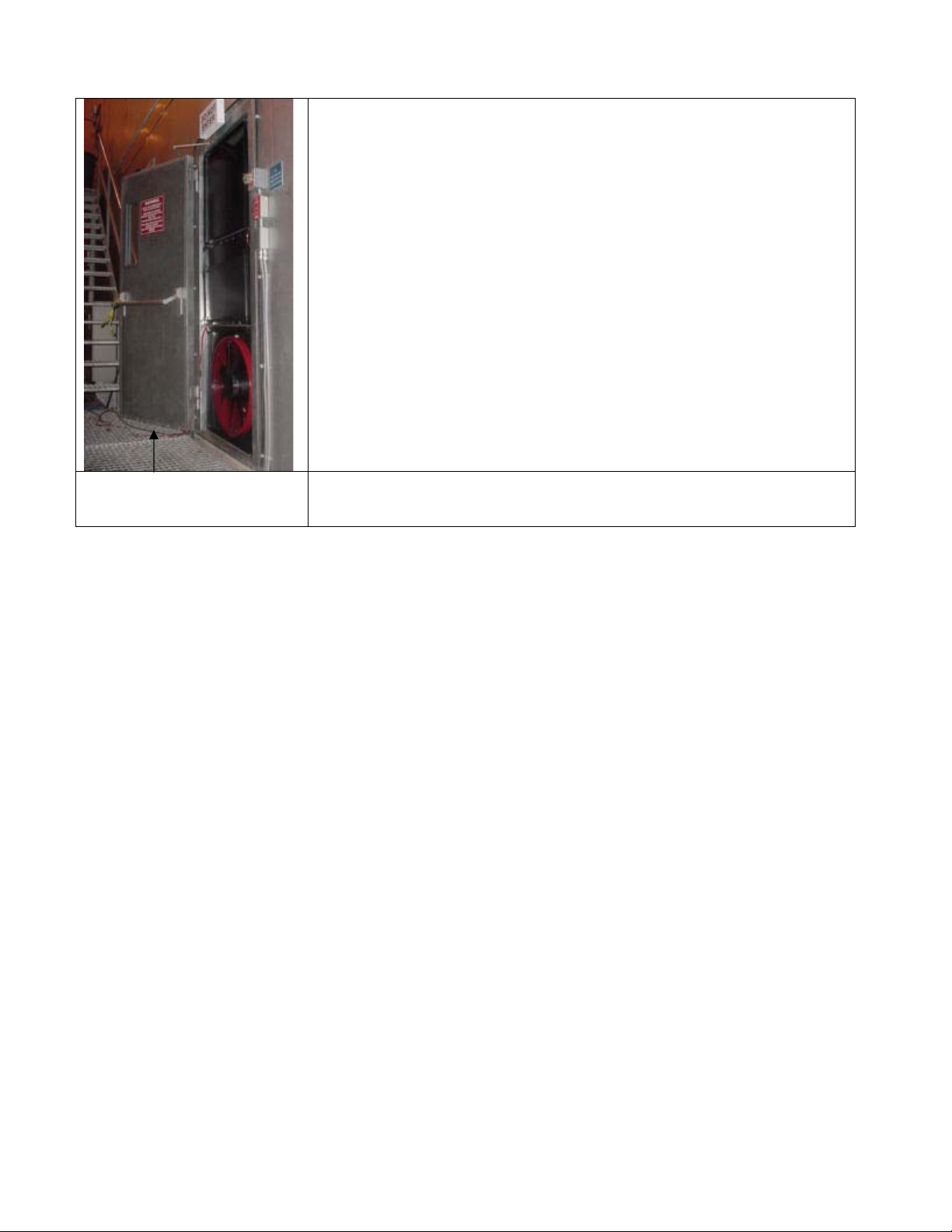
Single Blower Panel Set
Up
Large room testing with
2 Blowers
Range Selection
with Model N digital
console
Or, E43 Aluminum
Frame Set Up
Room and Flow
Pressure Readings
OR, Model L digital
control panel
Leak check at + 15Pa
Room pressure
Windy test conditions
OR, Model E analog
gauge clip
Smoke test &
measure static pressure
Mixing or NO mixing?
2000 Fire Door-Fan Manual updated 2002-05-28 Page 1 of 58
Page 2
What to do if room fails.
Field Calibration
Lower leak tests using:
Flex-duct ceiling
neutralization
Tall doorways
Lower leak tests using:
Plastic-on-Ceiling
procedure
Sub-floor Only tests using
Floor neutralization
procedure
Run from CA2001
Lower leak Estimates
using: Leak audit
Packing up and moving
equipment
Recalibration of
Large building Testing
…rent additional
equipment if needed
2000 Fire Door-Fan Manual updated 2002-05-28 Page 2 of 58
Retrotec Infiltrometer
Troubleshooting and
repair
Page 3
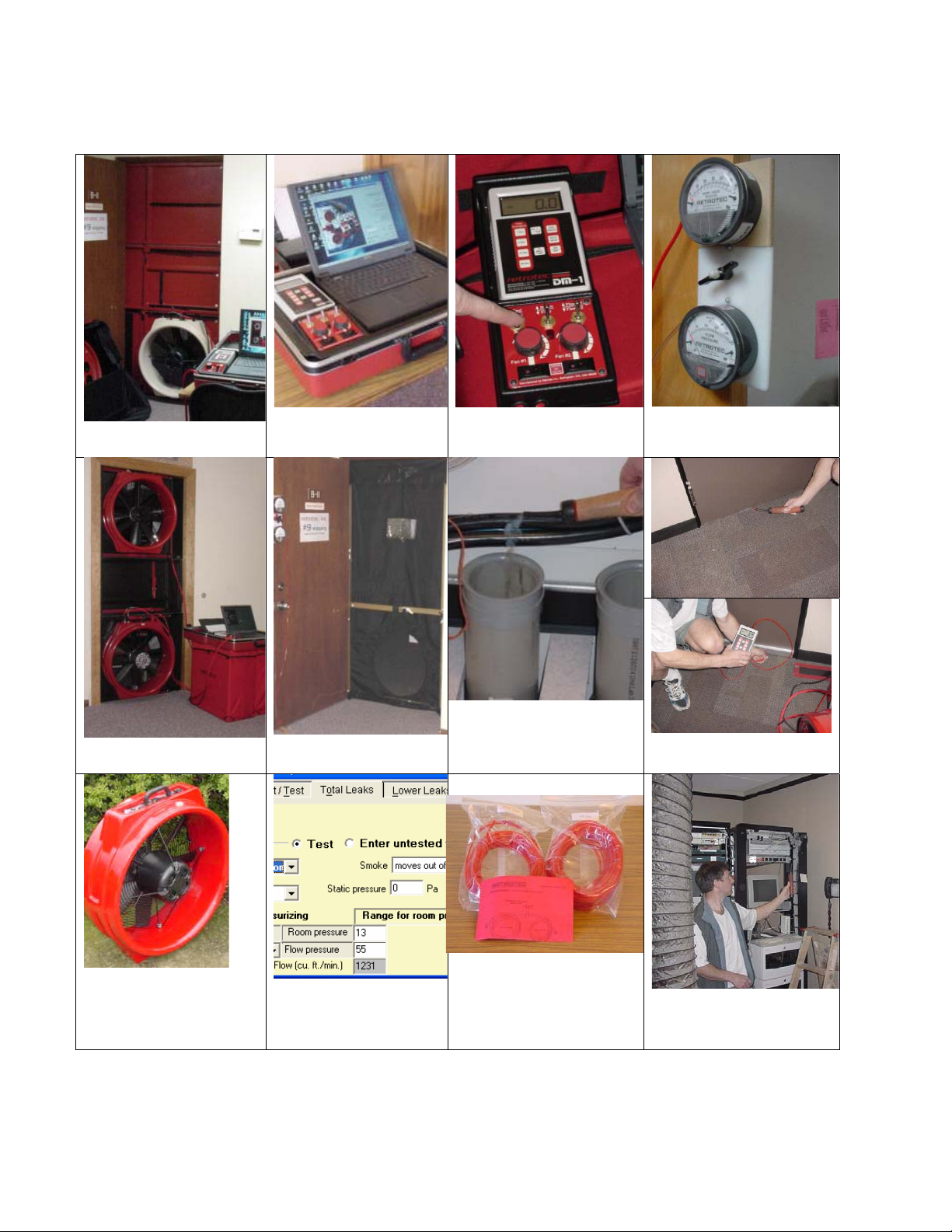
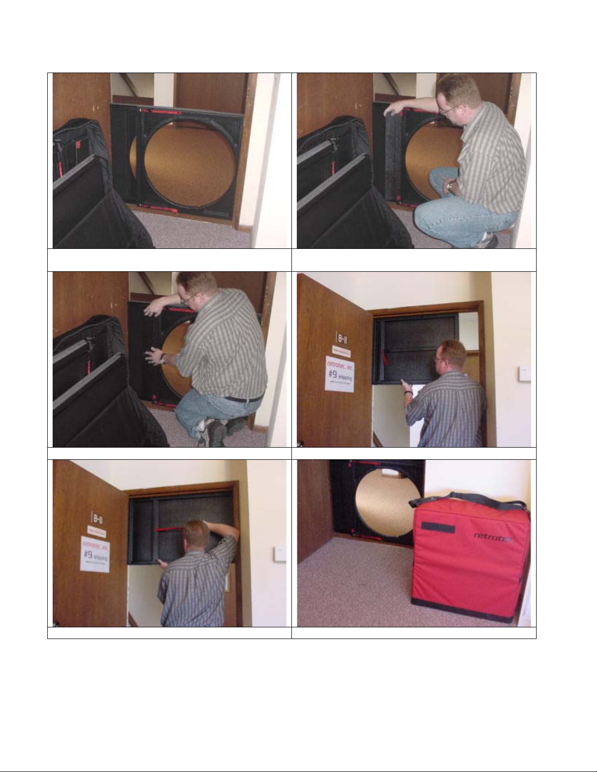
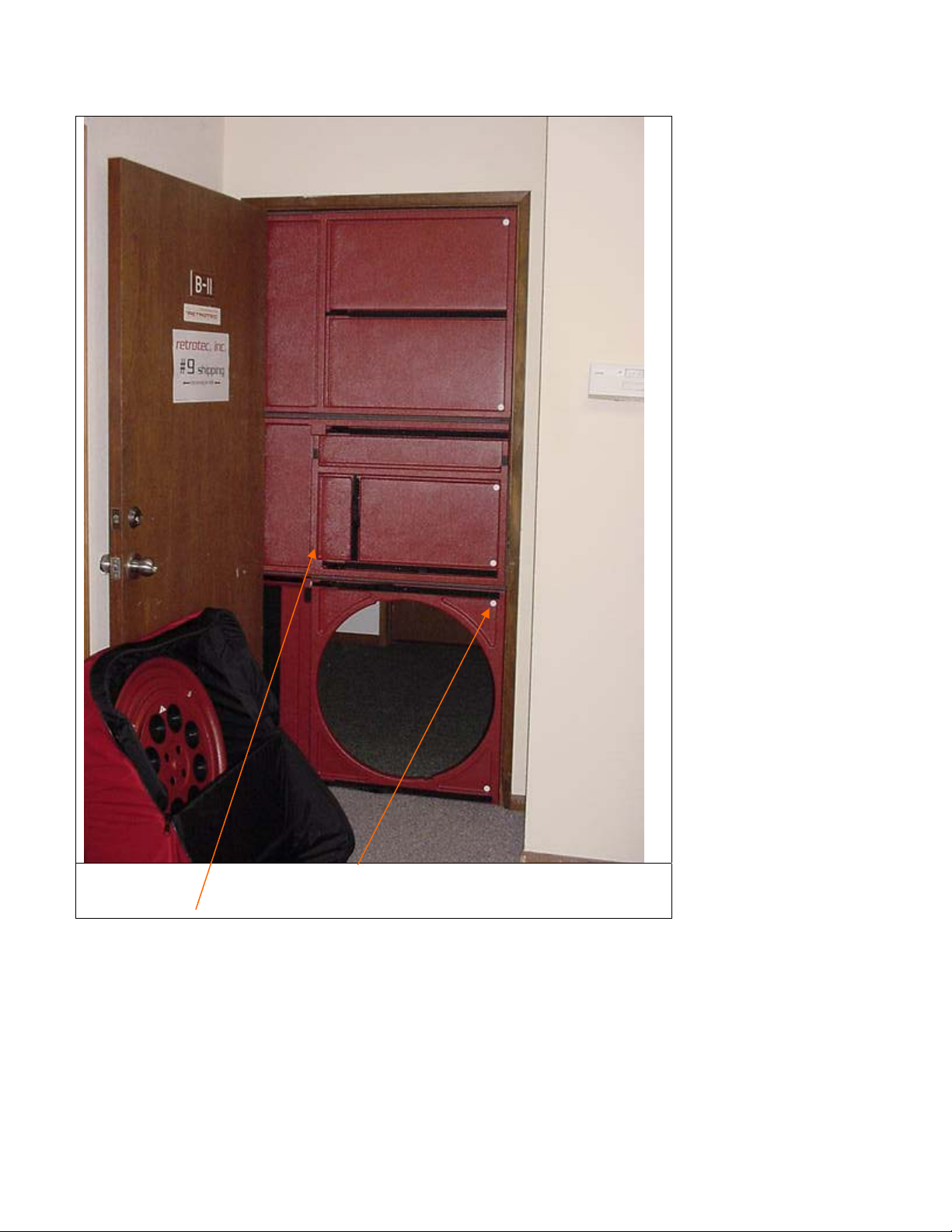
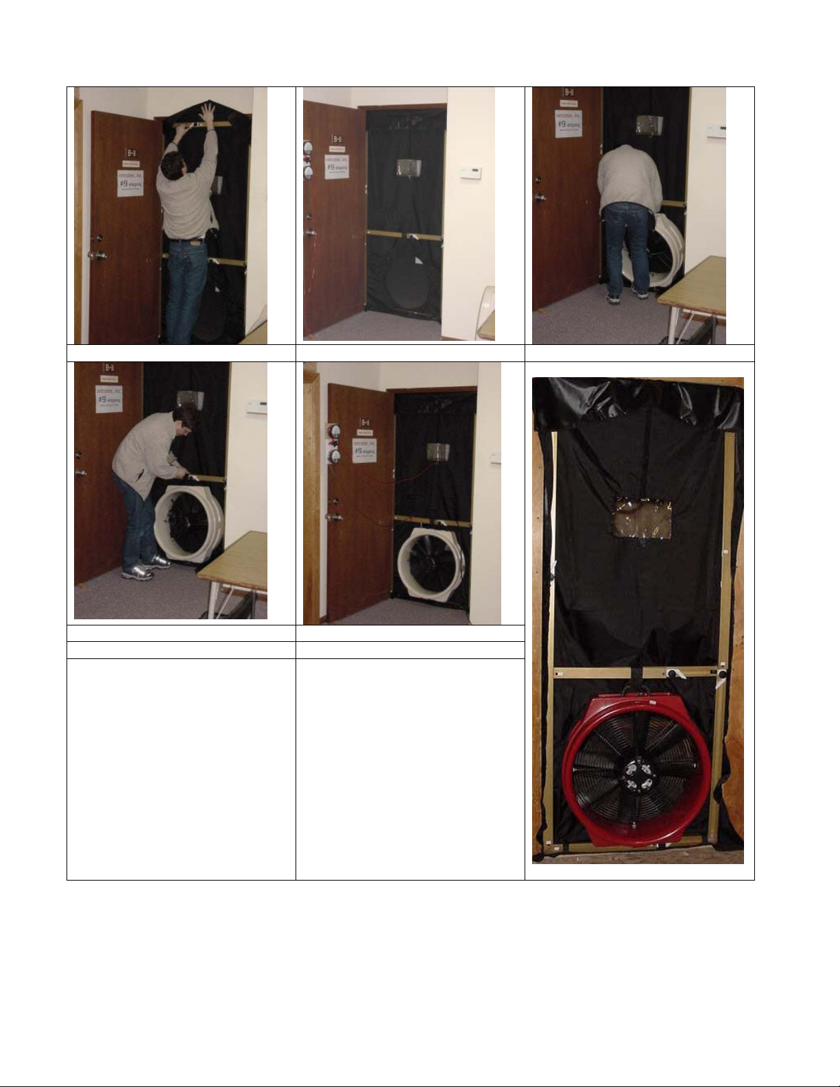
Single Blower Panel Set Up
Select a doorway where the air will be blown into
the largest space so the air can find its way back to
the leak. Set the panel bag close to the door.
Open Blower Panel and position back edge against
the doorstop.
Open panel bag and remove the Blower Panel with
the 22-inch hole in it.
Pull top strap tight and secure strap in the nylon
cleat. Press the loop against the Velcro to keep strap
ends neat.
2000 Fire Door-Fan Manual updated 2002-05-28 Page 3 of 58
Page 4
Cinch lower strap tight and secure strap in cleat. The small fill-in sheet is positioned first in the
Smooth down the fill-in sheet from top to bottom Place the large X-Panel in the top of the doorway.
groove. It fills in the gap for doors up to 36”
Cinch and lock the pull strap to secure the panel. Place blower case next to the doorway.
2000 Fire Door-Fan Manual updated 2002-05-28 Page 4 of 58
Page 5
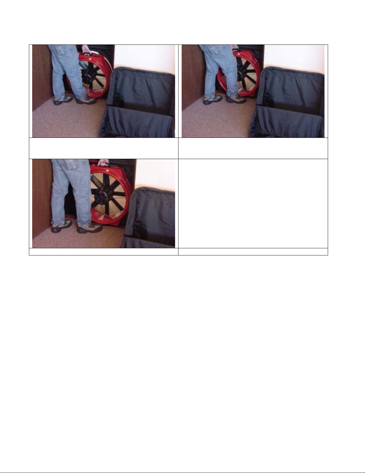
Hook the bottom foot on the blower through the
hole in the center of the panel.
Blower is upright and locked in place.
Align the nylon block on top of the blower with the
panel cutout, insert and rotate the blower till the
top is horizontal to lock it into the panel.
The blower is mounted in the Flow Away position.
This is always first. When the test is complete in
this direction, the blower is removed and installed
with the Flow Towards the operator.
2000 Fire Door-Fan Manual updated 2002-05-28 Page 5 of 58
Page 6
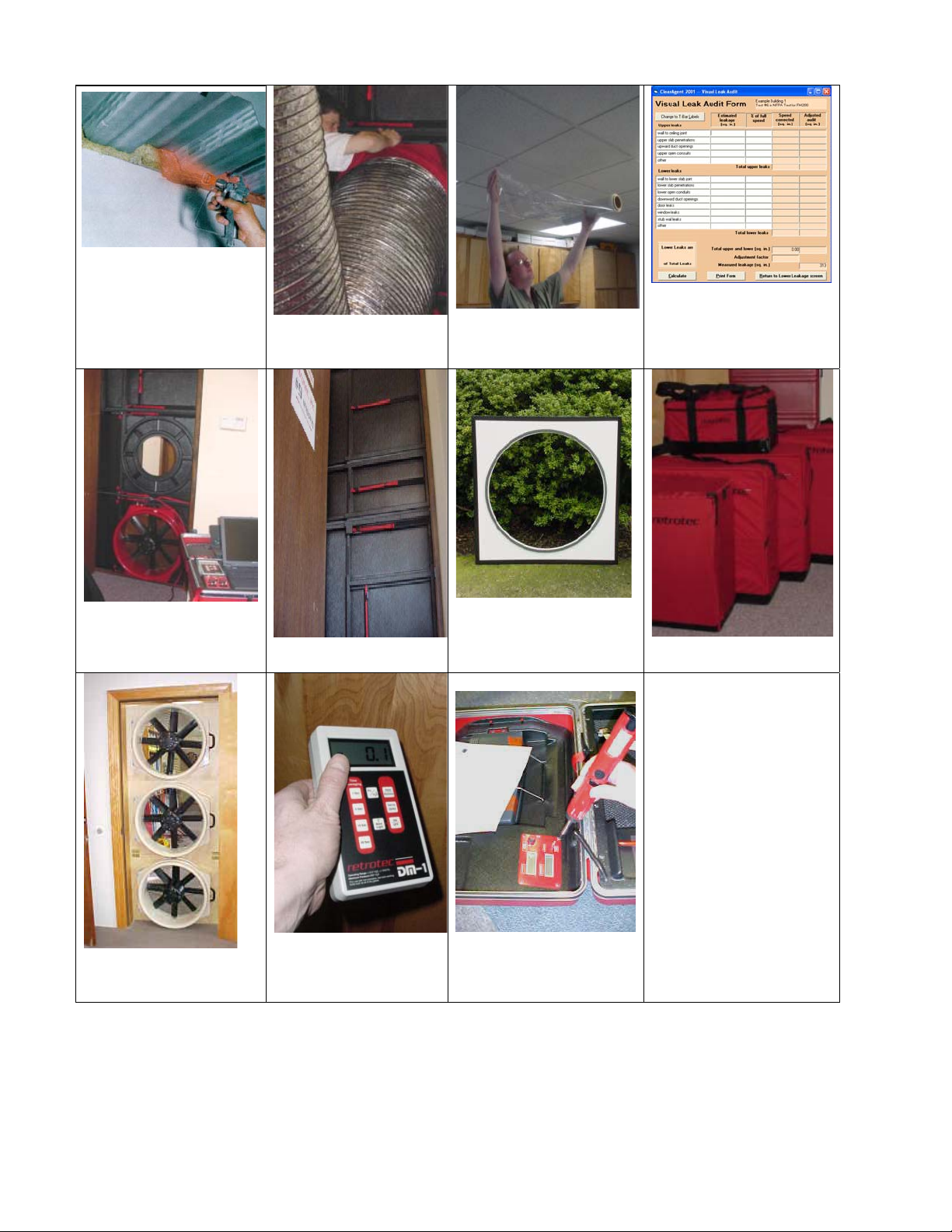
Set up Model N digital console
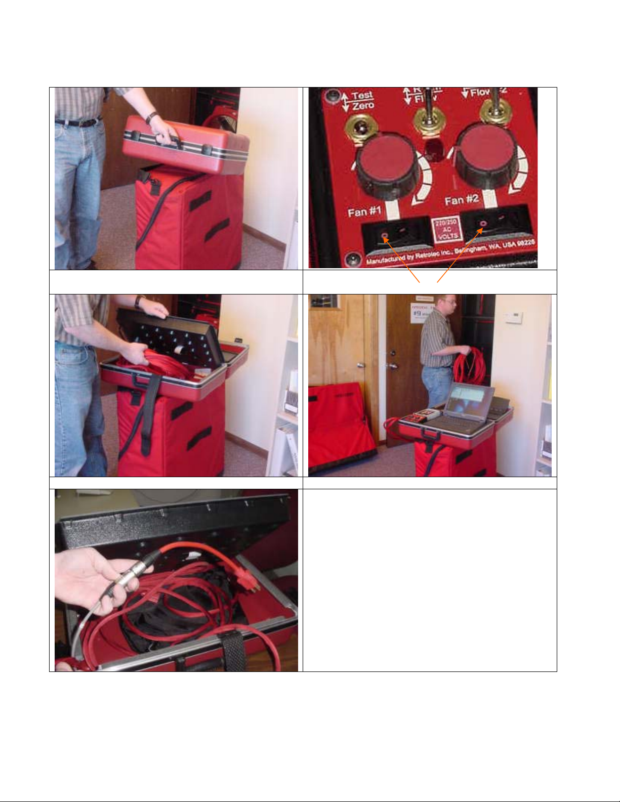
Place Laptop Console on blower case. Set rocker switches OFF by pressing the “0” so
blowers don’t come on accidentally.
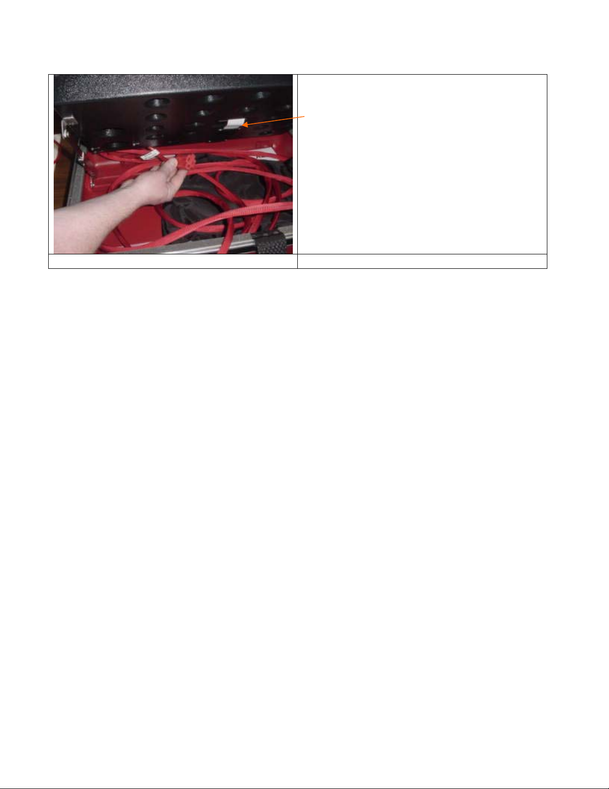
Remove the control cords Place the cords next to the panel set.
Power to console comes from:
1. Blower receives power from wall.
Cord from console picks up this
power to run the printer, computer
and thermometers.
2. When blower is not plugged in, the
console can get power from the short
adapter plug that fits onto the end of
the umbilical cord then goes to a
wall socket.
2000 Fire Door-Fan Manual updated 2002-05-28 Page 6 of 58
Page 7
Your laptop computer power supply plugs
into the female plug inside the console.
The power supply cord is then led through
this hole to the computer above.
2000 Fire Door-Fan Manual updated 2002-05-28 Page 7 of 58
Page 8
OR, Model L digital control panel for Models L64 and L63
The control panel can sit on top of the blower case with your laptop beside it.
2000 Fire Door-Fan Manual updated 2002-05-28 Page 8 of 58
Page 9
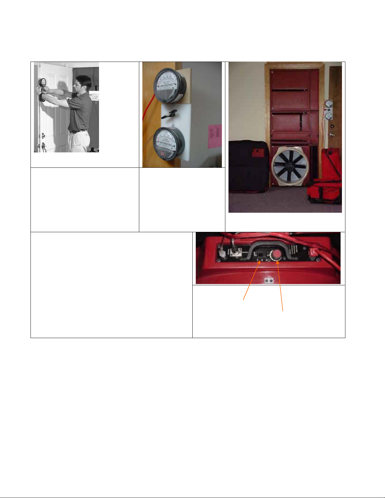
OR, Model E analog gauge clip for models E43, E53, E54
The Gauge Clip attaches to the door
or the Aluminium frame.
1. Loosen knob on gauge plate to
accommodate door thickness.
Gauges mounted on door.
Top 60-gauge slides up and
off to be used as handheld
as needed.
2. Hold gauges at eye level.
3. Rotate clamp to grip door.
4. Tighten knob.
Zero gauges by blowing in the tubes and capping them
off with your thumb so the gauge stays at the top of its
range for 30 seconds. If the gauge falls while capping
the tube, there is a leak, stop to locate and fix it. Let
the gauge fall back down and zero with small
screwdriver supplied. Do not turn more than 3 turns!
After another 30 seconds of gently tapping the gauge
front, adjust the zero screw at the bottom of each
gauge until it reads zero with the small slotted blade
screwdriver. Tap the gauge with your finger to
remove the mechanism's friction (hysteresis), and rezero if necessary.
Move rocker switch to the right then turn the
blower mounted speed control.
2000 Fire Door-Fan Manual updated 2002-05-28 Page 9 of 58
Page 10
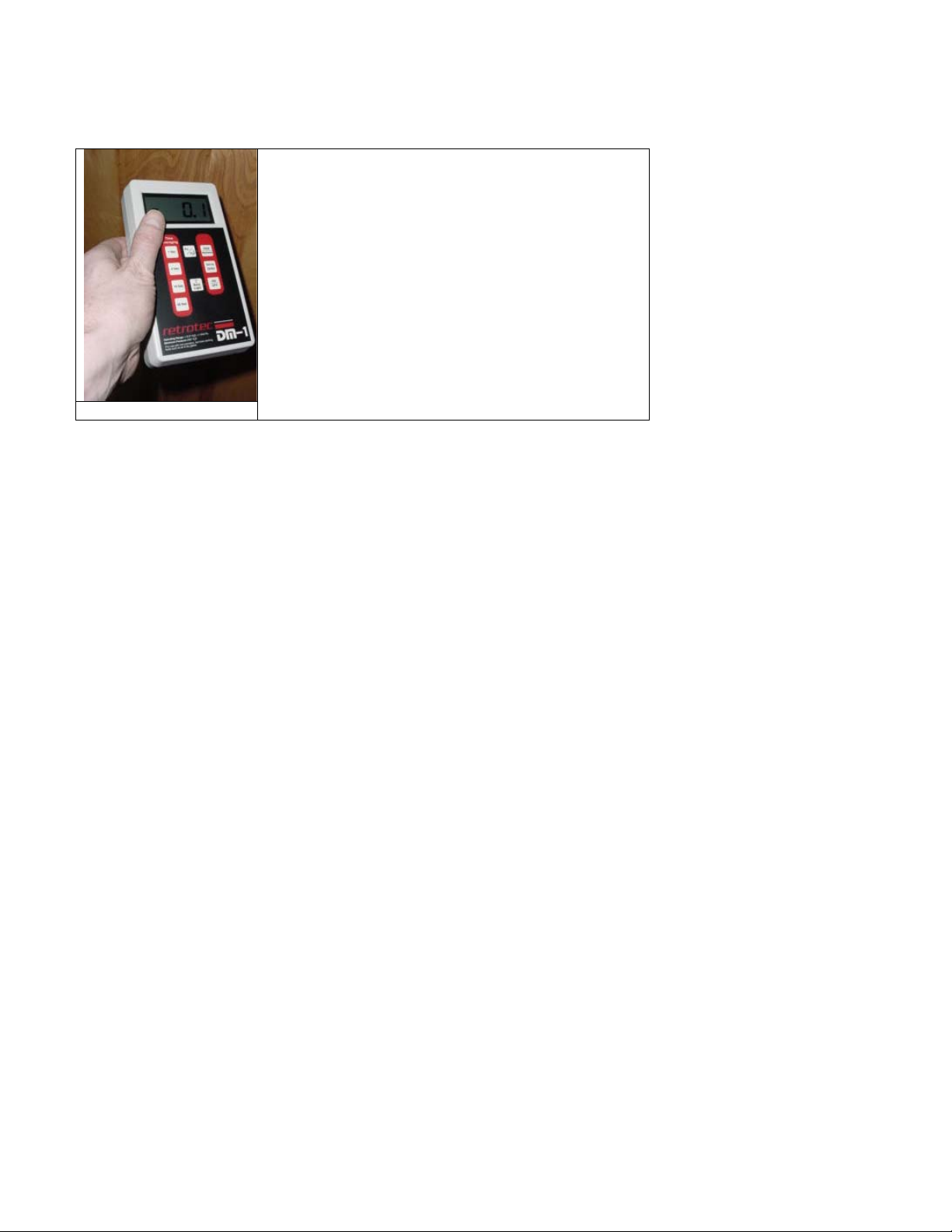
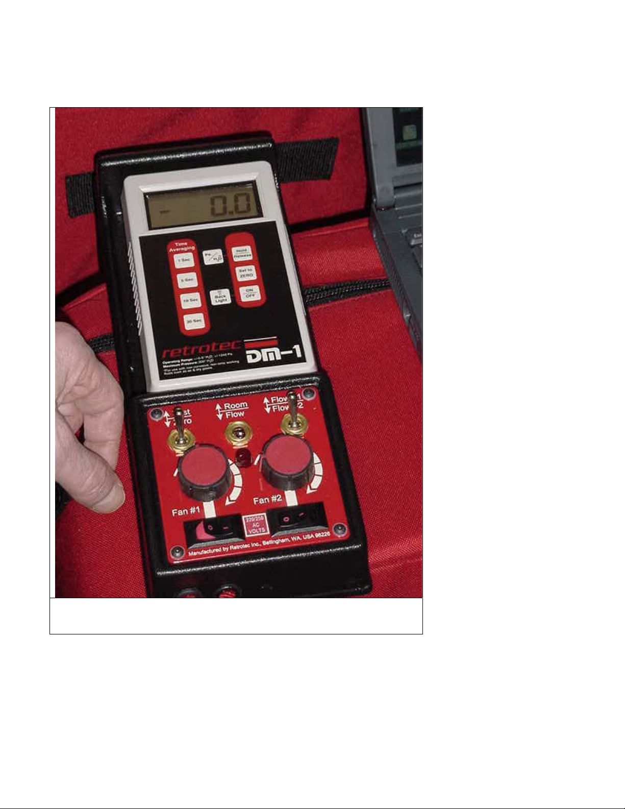
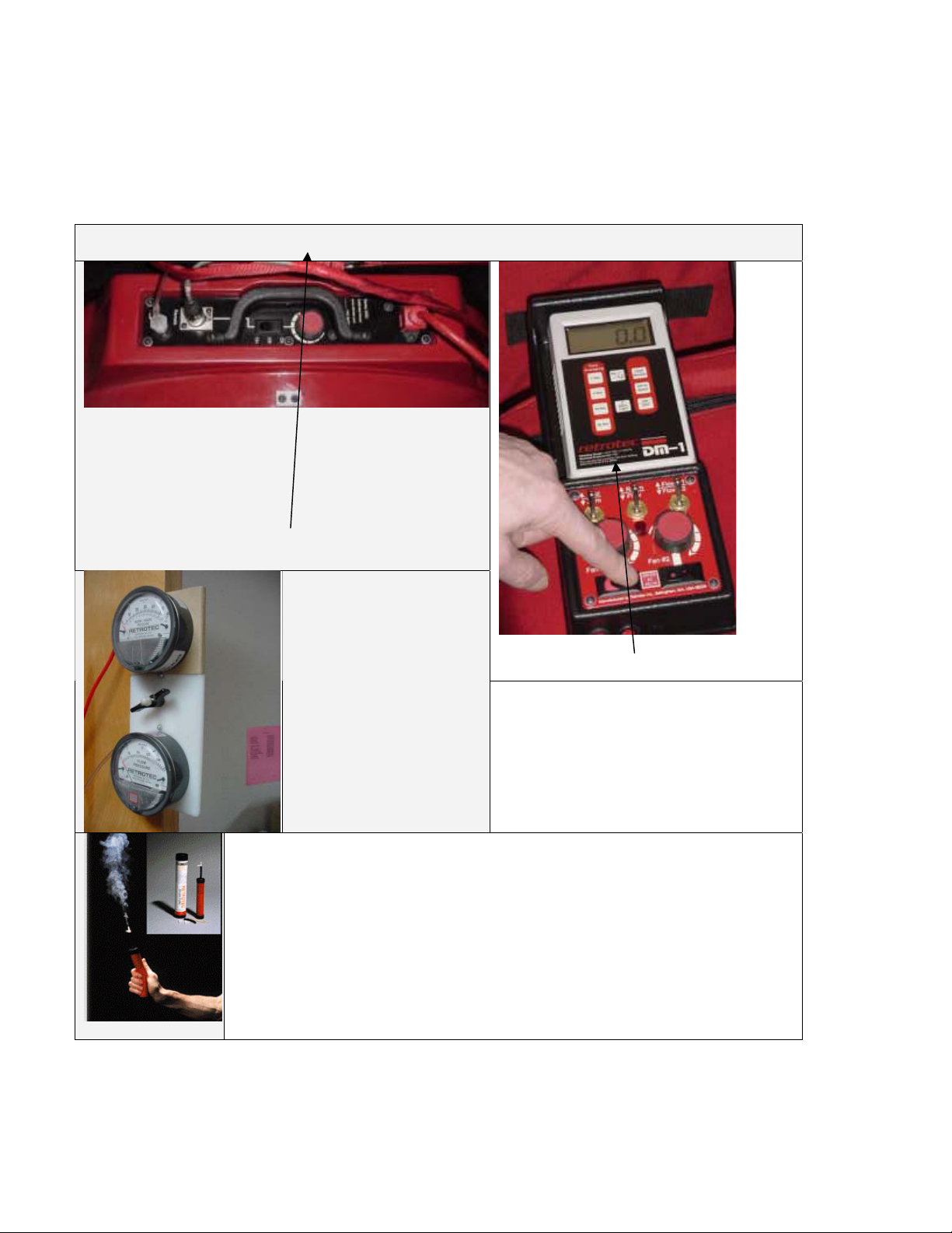
OR, DM-1 digital gauge for models J64
The digital gauge can be hand held and used to
measure static pressure, room pressure and flow
pressure. Connect a tube from the panel to the right
hand port of the DM-1 to get room pressure. Then
connect a tube from the DM-1 to the blower to get
flow pressure.
OR, DM-1 digital gauge
2000 Fire Door-Fan Manual updated 2002-05-28 Page 10 of 58
Page 11
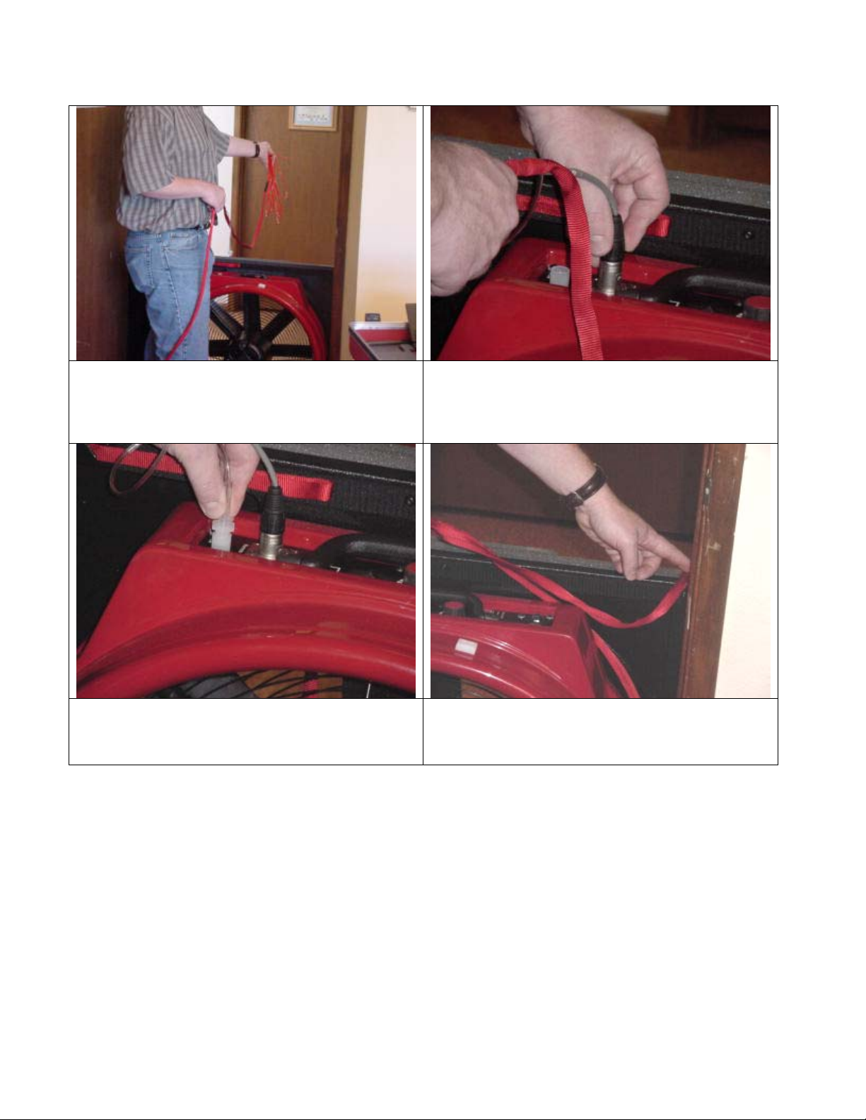
Take the 7ft red tube and throw outside, away from
the air blast of the door fan and if outdoors, away
from wind if possible. If you were testing from
outside the room, this tube would then get thrown
inside.
Plug the clear flow pressure pick-up tube into the
nylon quick-connect on top of the blower. Gently
push while giving it a quarter turn.
Insert the motor control connector into the
receptacle till it clicks.
E and J models will not have a control connector
since the knob on the blower is used.
Make sure the 7ft red cord and thermometer are in
the corner to the panel and the thermometer is on
the backside of the panel. Plug power cord from
Blower to wall outlet.
2000 Fire Door-Fan Manual updated 2002-05-28 Page 11 of 58
Page 12
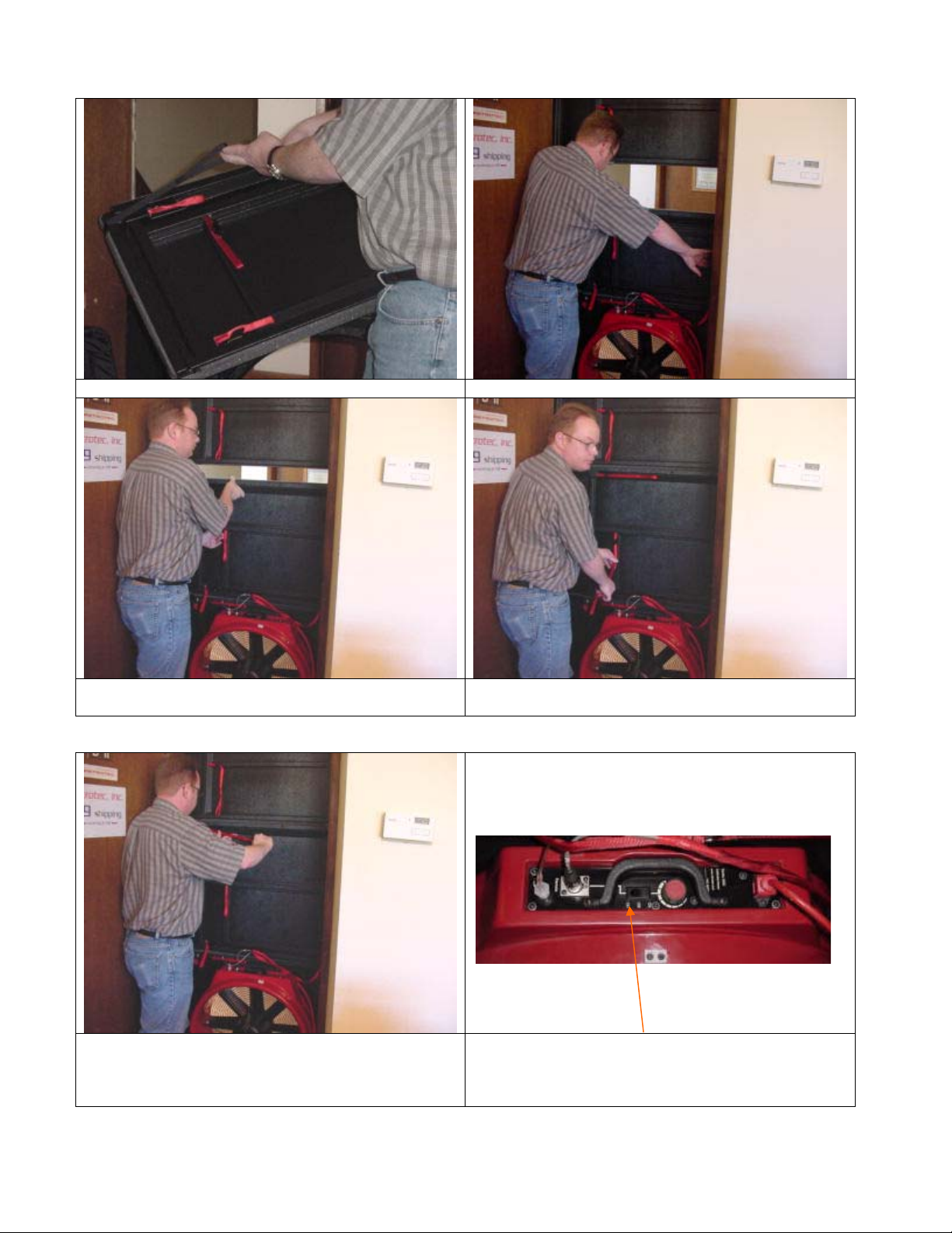
Install the X-Y Panel. Expand the X-Y panel horizontally by hand.
Expand the X-Y Panel vertically with the center
strap.
Tighten and lock the horizontal straps in their cleats. Ensure rocker switches are OFF at the control panel.
Cinch and lock the vertical strap in the cleat.
Plug power cord into wall outlet then into blower.
Set rocker switch on blower to “remote” so it can be
controlled by the console or control panel.
2000 Fire Door-Fan Manual updated 2002-05-28 Page 12 of 58
Page 13
Red tube is always extended
away from the air-stream on
the opposite side of the door.
2000 Fire Door-Fan Manual updated 2002-05-28 Page 13 of 58
Page 14
This detailed picture shows white dots that should line up. Later models may
have molded dots.
This vertical bar should line up on each sheet.
2000 Fire Door-Fan Manual updated 2002-05-28 Page 14 of 58
Page 15
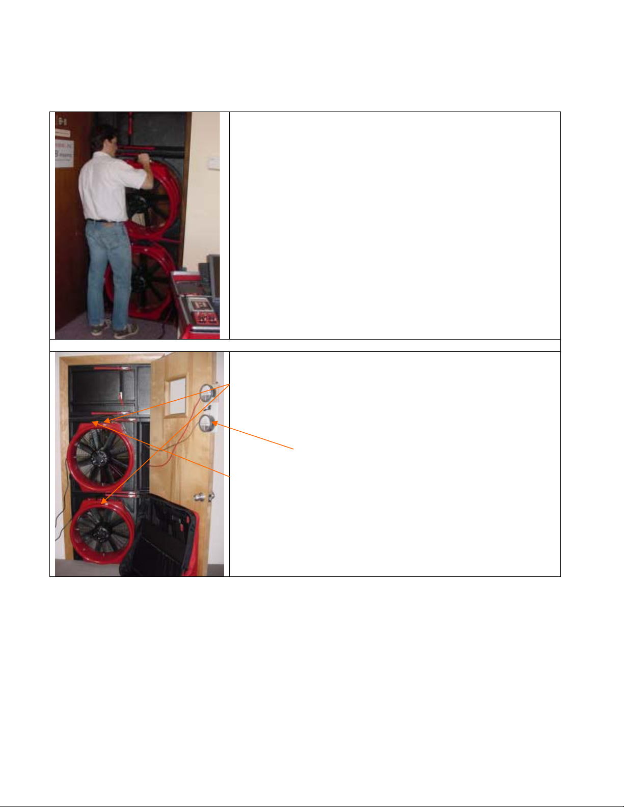
Large room testing with 2 Blowers
Models N64 and L64
Use the second blower panel. Install it above the lower blower
panel. Install the second blower in the upper panel. For added
security:
1. mount the panels on the far side of the doorstop so the
weight of the blowers pulls them into the stop
2. apply 2-inch clear tape to both sides of the upper panel
where it contacts the doorframe
Use second cord set from console to control the speed of blower #2.
Models E64 and J64
Use speed controls mounted on blowers to adjust speed.
Read flow pressure from blower #1 then move the flow pressure tube
from blower #1 and connect it to
blower #2 for second flow pressure reading.
2000 Fire Door-Fan Manual updated 2002-05-28 Page 15 of 58
Page 16
Or, E43 Aluminum Frame Set Up
Open case Take out pieces Assemble flat. Line up numbers.
Connect corners Fit frame loosely into doorway. Adjust knobs to hold the size
Cover with cloth Fit frame and cloth into door way.
2000 Fire Door-Fan Manual updated 2002-05-28 Page 16 of 58
Page 17
Actuate cam levers Frame is installed. Hook elastic under blower.
Use Velcro to hold blower Finished installation.
This install will take about 20
minutes the first time. It will
take less time with practice.
The main advantage of the
Aluminum frame is slightly smaller
package for shipment and lower
cost.
2000 Fire Door-Fan Manual updated 2002-05-28 Page 17 of 58
Page 18
Leak Check
The Purpose of the leak check is to locate the major leaks in the enclosure before performing the door fan test.
Often large holes are located that must then be sealed before the door fan test can begin. Sometimes the smoke
test identifies dampers that are not closing correctly or not at all. If so, that damper must be repaired before the
test can proceed.
Leak check. Blow air in to get +15 Pa room pressure & use smoke to locate leaks in:
9 Rocker switch selects between OFF, Local or
Remote.
9 With rocker in OFF position, plug red power
cord into wall outlet.
9 Clear tube and 5-pin connector are plugged in
9 Adjust speed from blower or console to get a
15 Pa room pressure. Ideal for finding leaks.
Analog gauge clip uses
speed control mounted on
blower.
Turn on DM-1.
Set all toggles into the UP position.
Speed control knob is first turned all the
way up till fan starts and then backed off
quickly to desired room pressure.
Retrotec Smoke Puffer is used to locate leaks and to detect airflow direction.
See section called:
It describes where to look for leaks.
Room Leak Location & Repair
2000 Fire Door-Fan Manual updated 2002-05-28 Page 18 of 58
Page 19

Smoke test & measure static pressure
The purpose of this test is to see whether there is a static pressure in the room prior to the
door fan test. The door fan is not running and smoke is puffed in front of an open hole in the
blower. If it moves slowly or not at all, no pressure exists. Minor pressures are cancelled out
by testing both directions so we are therefore looking for significant movement of 2 mph
(3kph). If the zone outside the enclosure is not completely connected with open doorways
then you must check across each wall this is not connected. Walls to outdoors can be ignored.
If there IS smoke movement, the magnitude of the pressure must be measured with the room
gauge or the handheld gauge.
Check to see if there is any static
pressure by puffing smoke near a
known hole at the door. If the
smoke moves, the next step is to
measure the magnitude since the
smoke is the best guide to its
direction.
See section called: “Smoke test & measure static pressure for more information.”
If the smoke moves, a
handheld gauge or room
gauge with tube under
doorway is used to
measure the static
pressure.
Analog handheld gauge
must be held firmly against
a vertical surface to ensure
zero shift is kept to a
minimum.
2000 Fire Door-Fan Manual updated 2002-05-28 Page 19 of 58
Page 20

Select Blower Range
Principles of Infiltrometer Air Flow Measurement
The Infiltrometer can accurately measure airflow between 18 CFM and 6500 CFM. However, in order to
measure accurately over this wide range, the range must be changed as described in the following section.
The Infiltrometer fan blade pushes air out the back of the fan creating a negative pressure in front of the
blades. This negative pressure pulls air through the fan's rounded (venturi) shaped inlet. More negative
pressure, more flow. The Infiltrometer has been calibrated so for each size of inlet opening and for each
negative pressure (Flow Pressure) the flow rate in cubic feet per minute (CFM) is known. As flow decreases the
Flow Pressure decreases eventually to the point that it becomes too low to read accurately.
By reducing the size of the inlet with the restrictor plate a given amount of air is forced to enter the blower at
a higher velocity, resulting in a much higher flow pressure. (The fan speed must be increased in order to pull
the same quantity of air through the blower with the restrictor plate in place.)
Therefore, as the flow rate requirement decreases, such as in tighter buildings, the size of the blower inlet
must decrease to maintain a high and accurately readable Flow Pressure. Each inlet size has a pre-established
configuration or range. Ranges are somewhat analogous to gears in a standard transmission car. The slower
you go the lower the gear.
Changing Ranges
The Retrotec 2000 Series Infiltrometer blower has 7 flow ranges for the greatest possible accuracy and
versatility.
Range 22 (wide open with no restrictor plate installed) is the most powerful and most commonly used range. It
is used to test buildings with ELA's greater than approximately two square feet.
To use range 22, remove all the restrictor plates.
Range A (1st restrictor ring attached) is the next most commonly used range. It is used to test House/Rooms
with ELA's between approximately one and three square feet.
Range B (2nd restrictor ring attached) is used to test House/Rooms with ELA's less than one square foot.
Ranges C8 requires the installation of the plate with 8 holes open, on top of the motor. Ranges C4 down to C1
require plugging some of the holes. Put plugs in the exact positions as shown - others will produce erroneous
results. These very restrictive ranges are needed when testing very small rooms.
Each plug must be gently worked into the hole, but be careful you do not push the Panels right out of the
doorway. (If the blower is ever turned around for reverse measurement, ensure none of the plugs have fallen
out by peeking through the screen.)
2000 Fire Door-Fan Manual updated 2002-05-28 Page 20 of 58
Page 21

Range Selection Procedure
Always start with the restrictor plate off - that's called Range 22 for the 22" diameter inlet. Give the speed
control a quick half turn to get the motor moving then QUICKLY turn the control DOWN if required. As you
increase the fan speed, the Room Pressure gauge will rise. If the room is quite tight, it will rise very quickly.
(Never let the Room Pressure rise above 60 Pa.)
Range Selection When Conducting A Single Point NFPA Test:
The general rule regarding range selection is that the motor must be running at least at half speed. If the
motor is running slowly, change to a more restrictive range so the highest possible flow pressure can be
measured for the greatest accuracy.
The computer will warn you if the flow pressure is too low. If necessary, keep changing to a lower and lower
range (more and more restrictive) until the Flow Pressure is much greater than the Room Pressure.
Range Selection When Conducting a Multi-Reading Test:
The ISO procedure and sometimes the testing of relief vent capacity must be done using Multi-Point Readings.
This is normally done at pressures starting at 60 Pa down to 10 Pa of Room Pressure. Taking 12 readings
roughly equally spaced with the greatest concentration of readings at the lowest room pressures will yield t he
best results.
The general rule regarding range selection is to start with the blower running at maximum speed on the 60 Pa
reading. The new software will allow multi-range readings to be taken but this takes more time.
Cannot Achieve Desired Room Pressure with Plate Off
Each Door Fan blower is capable of measuring about 10 square feet of leakage area at a room pressure of 10 Pa. If
the room to be measured has more leakage than this, there are two options:
Option #1: Use a second blower to produce more flow and add the flow readings. Do NOT add flow pressures,
they are not additive! Use the multi-blower feature of your software.
Option #2: Instead of taking the Room Pressure up to 10, test at a lower pressure. The computer will advise
of the amount of error possible.
Option #3: Have leaks sealed until the proper Room Pressure can be obtained. Inspect to ensure that all
dampers and doors are closed.
2000 Fire Door-Fan Manual updated 2002-05-28 Page 21 of 58
Page 22

Flow Range Diagram
Always start in the Flow Away position.
Adjust speed till room pressure is reached. Fan must be running at least at half speed and flow pressure must be
greater than room pressure. If not, insert the Range A plate and keep changing to lower ranges till motor is at
least half speed and flow pressure must be greater than room pressure.
Range 22 - Flow Away Range A - Flow Away
Range B - Flow Away Range C8 - Flow Away
Range C4 - Flow Away Range C2 - Flow Away
2000 Fire Door-Fan Manual updated 2002-05-28 Page 22 of 58
Page 23

Range C1 - Flow Away Range 22 - Flow Towards
Range A - Flow Towards. The inlet is now on the
other side. Look at “Flow Away” picture to see what
the inlet must look like.
Range B - Flow Towards. The inlet is now on the other
side. Look at “Flow Away” picture to see what the
inlet must look like.
Range C8 - Flow Towards. The inlet is now on the
other side. Look at “Flow Away” picture to see what
the inlet must look like.
2000 Fire Door-Fan Manual updated 2002-05-28 Page 23 of 58
Range C4 - Flow Towards. The inlet is now on the
other side. Look at “Flow Away” picture to see what
the inlet must look like for C2 and C1 ranges below
this one.
Page 24

Room and Flow Pressure Readings
Make sure the blower is running at half speed or more before taking any
readings.
Analog Gauge Readings
...from the Magnehelic gauges from the Model E Analog Gauge Clip
Tubing Connections:
For the 60-gauge- connect the red tube from the upper port through the panel. When the
blower is reversed, the red tube must be connected to the lower port.
For the 250-gauge, plug the clear tube from the lower gauge port into the blower.
Gauge Reading Rules
• Ensure the gauges are zeroed.
• Read the gauges very carefully! The 240 Pa marker is easy to misread. Please refer to
the diagram below for clarification.
5 Pa division
Your eye must be perpendicular to the gauge faceplate to remove "parallax error".
• Wait 15 to 20 seconds after the last speed control adjustment to let the readings
stabilize before writing down the test data or entering it directly into the computer.
(For optimum results tap the gauges lightly to remove hysterisis and get the most
accurate reading possible.) Take results from both Room Pressure and Flow Pressure
gauges simultaneously since they will sometimes move up and down together.
240 Pa marker
250 Pa marker
2000 Fire Door-Fan Manual updated 2002-05-28 Page 24 of 58
Page 25

60 gauge readings
Read the upper scale only. Reverse the tubes when you turn the fan around to test in the
other direction.
Taking Readings from Two Blowers
If one blower can't get adequate Room Pressure, remove the upper panel cover and install a
second blower. To be absolutely sure the upper panel will stay in place during the test,
tape the edges of the upper panel to the door frame using clear box sealing tape or
masking tape. Don't use duct tape.
Adjust one or both speed controls until the Room Pressure is at the pressure requested by
the Retrotec software. Ideally, adjust both blowers so that they are both running at about
the same speed, and producing approximately the same Flow Pressure. Don't have one going
flat out and the other idling. Both blowers must have their restrictor plates off, i.e. both on
Range 22. Go through computer program per usual, but choose the
multi-blower check off.
Read the Flow Pressure from both blowers and enter them into the
software separately. Do not add them! If you do not have 2 flow
pressure gauges in your system, read the bottom blower, then unplug the
clear tube #1 from the bottom blower and plug it into upper blower.
Read the upper blower flow pressure. Don't touch the speed controls
between reading one flow pressure and the other.
Enter the flow pressures one at a time. After entering them, you proceed
as usual.
2000 Fire Door-Fan Manual updated 2002-05-28 Page 25 of 58
Page 26

Digital Gauge Readings
Model DM-1 Digital Gauge for models N64, N63, L64, L63, J64, J63
1. Connect the 3 inch red tube from the Console or
Digital Control Panel to the right port of the DM-1.
Tips
Re-Zero … prior to taking a new set of readings.
Changes in temperature or position may affect the zero by 0.1 to 0.4 Pa but overall the drift
will be minor. It is best not to re-zero before a test is completed. Take readings for both
pressurize and depressurize without re-zeroing the DM-1. Small changes in zero are offset
by testing in both directions.
Time Averaging
Experiment with one-second time averaging for stable pressure conditions and longer
averages for windy conditions.
2000 Fire Door-Fan Manual updated 2002-05-28 Page 26 of 58
Page 27

1.Turn ON the DM-1. Wait 30
seconds. Set first toggle to
“ZERO”
4. When this light is lit, all
connections have been made at
blower and it’s ready to go.
Turn on the power to blower #1.
2. Press “Set to Zero” on DM-1 3. Set all toggles up. They should
be in the “Test, Room & Flow #1”
positions.
5. Adjust the speed control to
get the required room pressure.
The blower must run at half
speed or more. If not change to a
lower (more restrictive) range.
Read the room pressure for 30
seconds.
6. When the desired room pressure
is achieved, flip the toggle up to
“Flow”. Read the flow pressure
(Flow #1) for 30 seconds. Turn the
blower OFF with the rocker switch
and turn the blower around to test
the other direction. Go to Step 3.
2000 Fire Door-Fan Manual updated 2002-05-28 Page 27 of 58
Page 28

Two blowers for large rooms, (see also section on flex-duct testing)
Use the second control cord for blower #2. Install while the blower is on the ground, and then install the
blower in the panel.
Complete steps 1 to 3 on the previous page first. Then go to step 7.
7. Turn on the power to blower
#1 and #2.
9. When the desired room
pressure is achieved, flip the
toggle up to “Flow”. Read the
flow pressure (Flow #1) for 30
seconds.
8. Adjust the speed controls to get
the required room pressure. Read
the room pressure for 30 seconds.
10. Read the flow pressure (Flow #2)
for 30 seconds. Turn the blower OFF
with the rocker switches and turn
the blowers around to test the other
direction. Go to Step 6.
2000 Fire Door-Fan Manual updated 2002-05-28 Page 28 of 58
Page 29

Windy Conditions
A
If the gauges fluctuate more than 1 Pa due to wind, follow these steps to reduce the
fluctuations in the gauge reading.
Tip: instead of taking readings at low room pressures around 10 Pa, perform the test at 60
Pa room pressure. The effect will be to reduce the retention time slightly but overall the
test will be more accurate.
Plug the red tube into the
open end to the T on the 25'
+ 50' red wind damping
tubes. The tubes are placed
away from the building to
avoid the pressure pulse
that gets created when the
wind hits the wall. Cover
the end of the tube with
sheet material or a box to
stop the wind from blowing
into the end.
View from outdoors
Red. Tube from panel goes here
ttach 14 ft. red tube to wind damping
system
Wind damping system
2000 Fire Door-Fan Manual updated 2002-05-28 Page 29 of 58
Page 30

Use averaging on digital gauge to reduce the effect of wind.
Set the Time averaging to 5 seconds. If the second
reading varies more than 10% from the first reading,
set it to 10 seconds. If the variation is still too much,
set it to 30 seconds. Take at least three readings. The
last two must be within 5% of each other in order for it
to be useable.
2000 Fire Door-Fan Manual updated 2002-05-28 Page 30 of 58
Page 31

Deluxe Wind Damping System to Stop Gauge Needles Moving
If the room pressure gauge fluctuates more than 1 Pa due to the wind and the standard two
tube damping system does not reduce them sufficiently then the optional wind damping system
may be more effective. The time constant of the system is designed to decrease swings due to
wind.
If swings are due to other causes the wind damping system may not help.
Place the Deluxe Wind Damping System case on the ground/floor outside the room or building
to be tested. If it has not been stored at the ambient outside temperature, leave it for half an
hour to acclimatise before starting the test. DO NOT let the sun or any other heat source beat
on the capacity tank.
Plug the RED tube coming from the panel into the smallest connector (of the five) on the back
of the capacity tank.
Place the wind damping system in a box and close it up. The box must be on the opposite side
of the doorway from the pressure gauges and away from the air blast of the door fan and the
wind. This is very quick and often sufficient to stop fluctuations.
Observe the gauges. If still fluctuating more than 1 Pa, attach CLEAR tubes (in any
combination of lengths) to each of the four 900 connectors on the back of the capacity tank.
Lead the CLEAR tubes to areas around the enclosure as far away from the walls as possible.
Lay the tube flat on the ground and cover the ends with cardboard to stop air movement at the
end of the tube. DO NOT seal the tube ends.
Observe the gauge needle for at least 30 seconds with the blowers off to ensure wind effects
are understood then turn on the blower to establish the required pressure. Again, observe for
at least 30 seconds. Some experimentation may be necessary to get the best gauge readings.
CAUTION: Do not allow tube ends to dip into water because this will seal them off.
If the wind fluctuations are still too great.
Increase test pressure so the wind fluctuations are no more than 20% of measured pressure.
Do not try to measure the static pressure at time of door fan test. Call it zero.
Take the room to the same positive and negative test pressure.
Observe the readings for 60 seconds and take the average.
This procedure will give a slightly (5 to 20%) greater leakage area than a no wind test which
will reduce the retention time by 5 to 20% making the test failsafe.
2000 Fire Door-Fan Manual updated 2002-05-28 Page 31 of 58
Page 32

Mixing or No Mixing (Descending Interface) or Extended Discharge
Mixing means that as agent leaks out the incoming air is continually
mixed with the remaining agent in the room so that the
concentration is constant throughout. Mixing gives equal protection
to all levels in the enclosure. Sometimes the air-handlers must
remain running during the retention time to keep equipment cool.
Other times mixing must be used because protection is required at
high levels. Often mixing is unintentionally created by convection
currents caused by hot equipment of equipment cooling fans that
must remain on during the retention period.
The initial concentration must be made greater to allow for the drop
in concentration.
This icon is used throughout the program and on reports to show
that mixing will take place.
To determine if there is mixing, a smoke test must be performed
where small puffs of smoke are placed near the protected
equipment. If the smoke puffs immediately dissipate, there is
continual mixing. If in doubt, it is possible to pass both the mixing
and the no mixing cases.
No Mixing or Descending Interface means that as agent leaks out
the incoming air is NOT mixed with the remaining agent in the room
so that a layer of air forms on top of the agent. NO Mixing gives
protection only below the air-agent interface.
The greater the initial concentration, the faster the agent will be
lost.
This icon is used throughout the program and on reports to show
that NO mixing will take place.
2000 Fire Door-Fan Manual updated 2002-05-28 Page 32 of 58
Page 33

If the room fails
Equipment calibration is often blamed for these failures but in over 12 years of 500 companies
testing, it has never been a factor. It is usually that he room leaks too much. Airsealing looks
simple but should be left to Weatherization contractors; NOT general contractors who may think
they can do it but seldom can.
Enclosures with excessive leaks
Seal leaks at all elevations and retest.
Enclosures with excessive upper leaks
These rooms may not pass the whole room test because of excess leakage where the walls
connect to the upper slab. Just like for any other room, seal all leaks below ceiling, even very
small ones. The floor slab to wall joint must be sealed throughout. Don't worry as much about
leaks through electrical outlets and switches.
1. For rooms with suspended ceilings, do a BCLA flex duct test. Depressurize the entire
space above the false ceiling.
2. For smaller rooms (up to 1000 square feet - about 250 lb. of agent) use polyethylene
taped under suspended ceiling. Test in positive direction only; the software will
adjust measured ELA based on static pressure. You may also cover and register or
duct coming out of the ceiling.
3. BCLA may also be estimated with AHJ and entered manually. Use the spreadsheet on the
Lower Leak tab.
4. Accept larger rooms with thorough smoke pencil inspection per 4-7.2.3 The AHJ should
not be able to uncover any remaining discernible leakage.
Increase agent quantity?
Grace FS 3000 Elastomeric coating is the best
solution to the biggest leak. It has a fire rating and
flexes so it does not crack and fall out when the
floor moves under load.
2000 Fire Door-Fan Manual updated 2002-05-28 Page 33 of 58
Page 34

This will only help if there is continual mixing during the retention period. If the airhandlers are shut off at discharge, more agent will give less retention time.
Rooms with suspended ceilings will double the retention time usually when agent is
discharge above the ceiling for mixing and no mixing cases.
Extended discharges will increase retention time for the duration of the discharge.
Eliminate Static pressure during retention
In cases where this is large, reducing it can increase the time.
Reduce High Static Pressures if present
Have the building HVAC shut down on discharge if possible. Test run the enclosure without the
static pressure to see if it will make enough difference to have it done.
Reduce the Minimum Protected Height
Determine what exactly needs to be protected in the room for the required retention time.
Open up the cabinets to see if they have anything in them or can a lower level be chosen.
Reduce the Minimum Required Retention Time
Base this on the response time of the fire department or local operators who would be trained
to deal with the fire event. See Step 12 in the Guide for help.
Improper training of testing technician
Learning how to operate the software and hardware and analyse room problems is often a huge
factor in passing enclosures and avoiding future problems.
2000 Fire Door-Fan Manual updated 2002-05-28 Page 34 of 58
Page 35

Flex duct installation for ceiling neutralization
Position the flex-duct case under the ceiling tile in
which it will be installed and open the case. There
must be minimal obstructions to airflow above and
around the ceiling tile selected.
. Hook the cuff under the lower foot of the blower
and over the nylon block on top of the blower
flange.
Insert the flex-duct into the T-bar ceiling
framework. The square sheet goes in next.
Secure the Velcro cinch strap on the flex-duct
blower cuff.
2000 Fire Door-Fan Manual updated 2002-05-28 Page 35 of 58
Page 36

A ceiling tile is removed to allow the flex duct to
be mounted
The upper blower is measuring lower room leaks
whilst the lower blower neutralizes leaks above the
ceiling.
Note how the flex-duct mounts in one half the tile
opening whilst the Retrotec blanking sheet that
comes with the flex duct fills the rest of the space
previously occupied by the ceiling tile.
In the corner is a 2x2 ft. grille leading to the ceiling
plenum. This grille should be sealed off to better
allow the ceiling to be neutralized.
Both fans are running. The ceiling tile is lifted to
see which direction smoke travels to determine
ceiling neutralization. When the smoke does not
move the lower leaks can be measured.
2000 Fire Door-Fan Manual updated 2002-05-28 Page 36 of 58
Page 37

Lower leak tests using: Plastic-on-Ceiling procedure
This procedure is much more time consuming than using the flex duct. It consists of
measuring the Lower Leaks by covering the ceiling with plastic. This takes a lot of time but
does give good results particularly in small rooms.
A temporary solid barrier to leakage through a suspended ceiling can be used instead of the
neutral pressure used in the B-2.6.2 "Flex Duct" test. The most commonly used material is 2 or
4 mil polyethylene plastic ("visqueen"), under the ceiling tiles, taped to the T-bar grid and
perimeter walls using 2" paper masking tape.
There are two distinct situations where this technique may be appropriate:
1) If the room does not have slab to slab walls, or
2) If the room is too small for a standard BCLA Flex Duct test (e.g. less than 250 to 500
sq.feet of floor area).
While this approach could be used on a room of any size, it is rarely used on rooms larger than
approximately 1,000 square feet, for the following reasons:
1) The larger the area, the more expensive and disruptive the test becomes.
2) If the room is greater than 500 square feet and has slab to slab walls, a BCLA Flex Duct
test can generally provide acceptable predictions, and
3) If the room is greater than 1,000 square feet, a through smoke pencil inspection per 4-
7.2.3 of the standard can provide sufficient assurance that no significant below ceiling
leakage exists which would cause an unacceptable halon loss. If the smoke pencil
inspection missed some leakage, it is unlikely that this overlooked leakage will be
significant enough to cause the room to fail. It is important to recognise that the larger
the volume, the less sensitive the room will be to leakage. If two rooms are built to the
same relative standard of construction, the smaller one will lose halon faster due to its
less favourable surface to volume ratio.
The plastic under the ceiling technique is the Appendix C procedure.
“CB-2.6.2.9 An alternate method for measuring the below ceiling leaks consists of temporarily
sealing identifiable ceiling level leaks using a flexible membrane, such as polyethylene sheet
and tape, and then measuring the below ceiling leakage solely using door fans drawing from
the lower part of the room. No flex duct is needed. Examples of sealable leaks are
undampered ceiling level supply registers or return grills, or an entire suspended ceiling lower
surface.”
2000 Fire Door-Fan Manual updated 2002-05-28 Page 37 of 58
Page 38

The principal deviation from the normal procedure is that the test can only be conducted in
one direction, i.e. as a pressurization test. Depressurizing almost inevitably pulls down the
plastic.
In a room without a suspended ceiling, plastic could be used to seal off undampered ducts at
ceiling level to better determine how much of the room leakage is below ceiling level. Note
that unsealed cracks at the roof wall joint would now be assumed to form part of the BCLA,
resulting in a more conservative retention time (perhaps too conservative). In such a situation,
the test can usually be done in both directions, as the plastic can be adequately restrained.
Conducting the Test
The standard Whole Room Test must first be conducted to determine the whole room ELA. No
temporary sealing of any openings is permitted.
Installing the plastic is simply a question of time and common sense. The plastic doesn't have
to be heavy duty - 2 mil seems to be a good compromise between light-weight and workability. Fresh 2" painter’s masking tape sticks well and doesn't peel off the paint. Cutting the
plastic into approximately 10 feet wide strips makes it easier to install. Avoid attaching the
plastic to sprinkler heads! Make sure the wall edges of the plastic are taped to the wall, not
just the T-bar.
Run the test from the Lower Leak tab of CA2001 and choose “Plastic on the ceiling test”.
Perform the test in the pressurization mode only.
If the BCLA Plastic test fails, and your smoke pencil inspection finds more leaks below ceiling
level to be sealed, you should theoretically remove the plastic, redo the Whole Room ELA test,
and then re-install the plastic and redo the BCLA test. Obviously, this is not practical. An
alternate approach is to seal the leaks and redo the BCLA test until the room passes, using the
original Whole Room ELA value. There is no real need to redo the ELA test, as using the
original value will give a slightly more conservative retention time than would be obtained with
an actual final Whole Room ELA measurement. Of course, the Whole Room ELA can be
remeasured and the results rerun after the plastic is removed.
Fastest Way to Seal the Ceiling or Register (Grilles)
Retrotec sells a product called Grille Mask. It is a brightly colored masking tape looking
material. It comes in 8 inch wide rolls so it is very fast to apply. A case of five 200 ft. rolls
currently sells for $125 plus $29 for a waist belt to hold the duct mask while sealing registers.
Overhead applications, such as sealing T-bar’s are best done with a paint roller and long
extension handle. Only the join in the T-bar needs to be taped over. Pay particular attention
to the corners.
2000 Fire Door-Fan Manual updated 2002-05-28 Page 38 of 58
Page 39

Lower leak Estimates using: Leak audit
Set the door fan to produce a 15 Pa positive pressure. Open the door panel up to witness
smoke moving at “full speed”. Locate enclosure leaks, measure the open area. Test the
leak with smoke in the area where the leak was measured. Mark down the % of full speed
that each leak appears to be. This will tell you whether something upstream from the
leak was slowing it down so in effect by knowing the area and speed you are determining
the approximate effective size of each leak.
Mark this data down for later entry into the Leak Audit button on the Lower Leak tab that
lights up when you enter “Estimated”.
See the CA2001 Software Instructions.
2000 Fire Door-Fan Manual updated 2002-05-28 Page 39 of 58
Page 40

Field calibration check with calibration plate
Place the second Blower Panel on top the first
Blower Panel and expand into position.
Place the X-Y Panel on top the Blower Panel. Tighten and lock the X-Y Panel straps.
Insert the fill-in sheet in the Blower Panel.
Panels installed with upper panel cover with
calibration holes ready for performing the field
calibration test.
2000 Fire Door-Fan Manual updated 2002-05-28 Page 40 of 58
Fielded Calibration Plate opened.
Page 41

The Field Calibration Check is a procedure which enables the AHJ to determine that the door
fan to be used on a test is sufficiently accurate, and that the technician knows how to operate
the equipment. It is also a useful training exercise for an inexperienced operator gaining
familiarity with the equipment.
The Infiltrometer is set up to measure the BACKGROUND leakage of a small room.
Next, a hole of known size is opened up and the room is re-measured with the Infiltrometer.
The new increased leakage area reading should be the sum of the first, plus the known hole
size. The difference between the actual increase and the measured increase is the
Infiltrometer and/or the operator error, e.g.:
1. The room is measured at 200 square inches of leakage area.
2. A 144 square inch hole is opened up.
3. The new leakage area should read: 200 + 144 = 344 square inches.
4. If the Infiltrometer measures the new total leakage area at, say, 350 square inches, the
difference is 350 - 200 = 150 square inches, which is (150 - 144) = 6, 6/144 x 100% = 4.2%
error.
NFPA 12A and 2001 specifies that the door fan system has to be within + 15%.
This test should be performed from the Field Calibration tab of CA2001.
2000 Fire Door-Fan Manual updated 2002-05-28 Page 41 of 58
Page 42

Tall doorways
Small X panel being installed. X- Panel will add 10 inches to the height of the
panels.
The small and large X-Panels can be positioned
above this panel set to fill doorways over 10 ft. tall!
2000 Fire Door-Fan Manual updated 2002-05-28 Page 42 of 58
Page 43

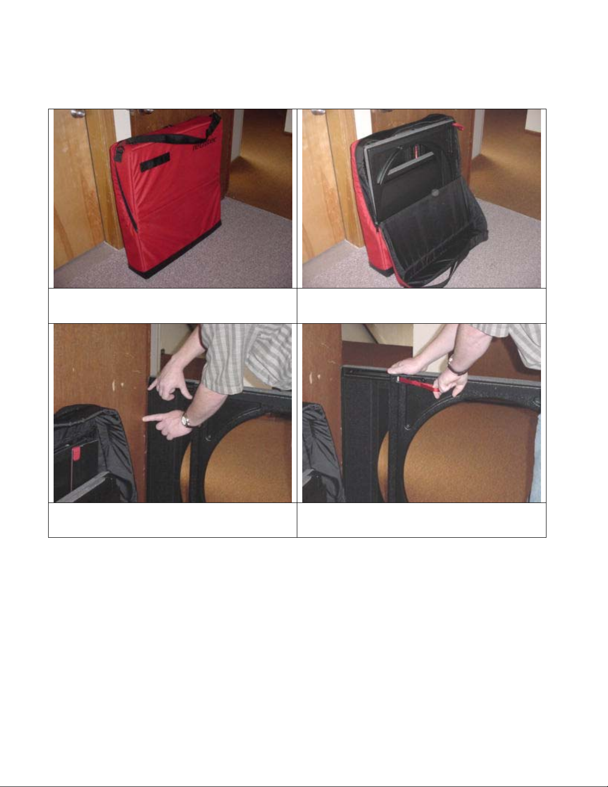
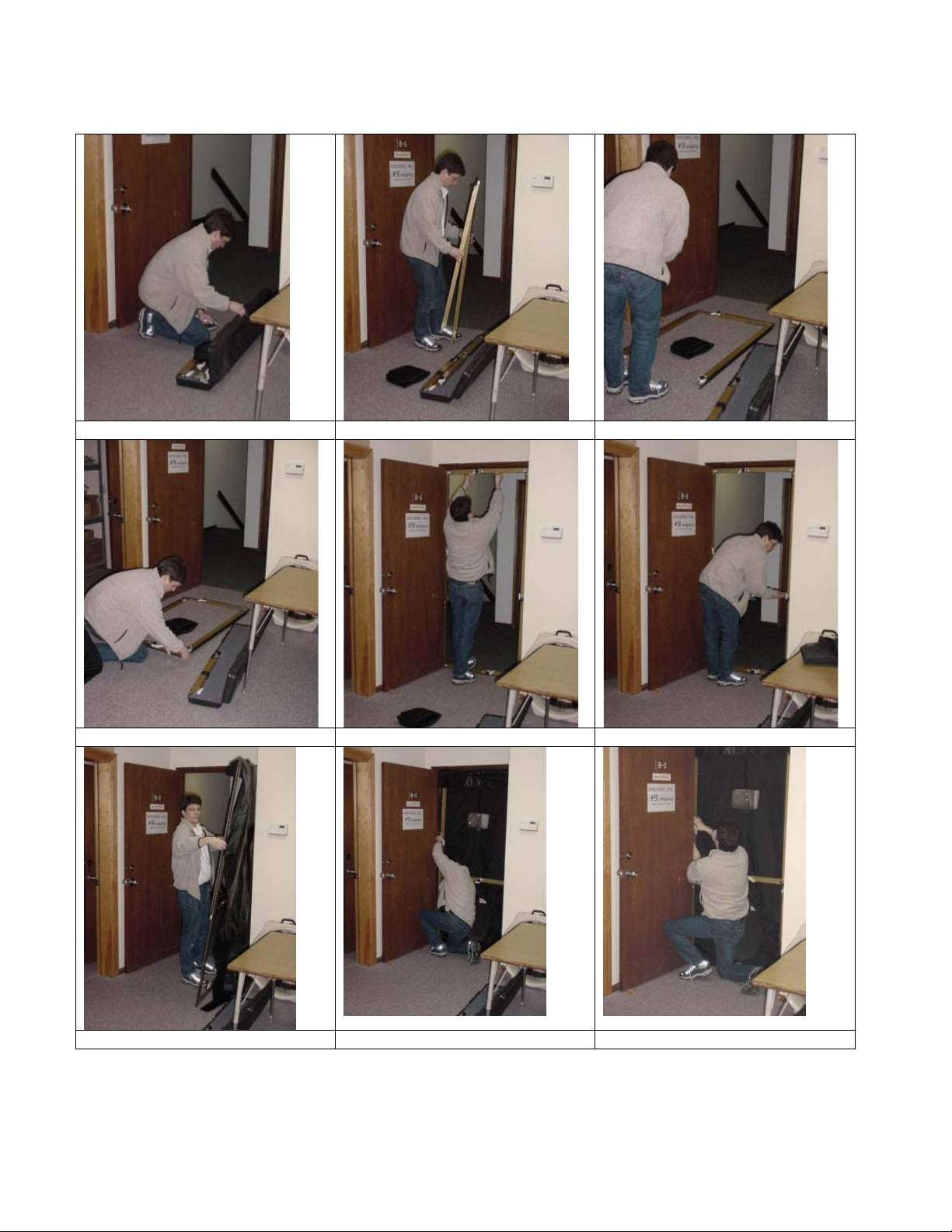
Packing up and moving equipment
Blower case fits on Ruaax cart.
Panel case goes over top Accessory bag goes on top. Console is carried.
2000 Fire Door-Fan Manual updated 2002-05-28 Page 43 of 58
Page 44

Case protects blower for day to day transport but
when shipped by separate carrier such as UPS the
case must be placed inside its original shipping box
or the equivalent.
Make sure the smoke puffers go into the special
outside pockets they were designed for. If packed
inside a computer case they may destroy the
computer!
Packing must be marked so it gets put back in the
same way.
Cart folded up.
2000 Fire Door-Fan Manual updated 2002-05-28 Page 44 of 58
Page 45

Large building Testing
Retrotec’s multiple fan panels can be added in modules to test any building of any size. It is
very rare to require more power than the standard double blower system but if needed,
Retrotec can rent as many blowers as needed for any job.
In the UK, air leakage tests must
be carried out in accordance with
CIBSE TM23 on all buildings over
1000 sq.m. The Retrotec Model
M55 shown will test enclosures up
to 2880 sq.m. of envelope area at
the minimum allowable leakage
of 10 cu.m/hr./sq.m. It can be
expected that much larger
buildings can be tested with the
same system if they perform
better than this minimum.
Using two systems in
two doorways or in
one double doorway
will increase the
envelope area to
5,760 sq.m.
Retrotec software
will handle up to 18
blowers allowing for
testing of buildings
with 17,280 sq. m.
of envelope area.
Retrotec equipment,
software and field
training expertise
are available
immediately.
The latest draft of Approved
Document L of the Building
Regulations (Conservation of Fuel
& Power) which covers England &
Wales was published in April this
year. Following approval by the
European Commission this draft
will be finalized and published in
August 2001, becoming effective
from February 2002. From this
date all plans submitted for
Building Control approval must
comply with these new
requirements.
2000 Fire Door-Fan Manual updated 2002-05-28 Page 45 of 58
Page 46

Recalibration of Retrotec Infiltrometer
The NFPA Appendix C requires recalibration of only the room pressure gauge
exchange 60 Pa. gauge and be sure to specify whether the tubes go out the back for the model 870 “kickstand
model “ or out the side for the model 970 suitcase style. Gauge clip styles all go out the side.
Users of CA2001 software will be supplied with a new calibration file to download that will record the required
date and update your software’s printout of its calibration data.
The NFPA Appendix C requires recalibration of the complete system every 5 years. The entire system must be sent
back for recalibration and checking in our flow chamber. Send back both blowers, low flow plates and console.
Panels don’t need
New certificates will be issued.
Our series 600, 700, 800 and 900 and 2000 flow measurement systems do not require more frequent recalibration
unless they are damaged to the extent that their physical dimensions are changed drastically, or if Field
Calibration Checks repeatedly show that the system is inaccurate.
The measurement method used in our system relies upon the physical dimensions of an annular nozzle which has
well-documented flow characteristics. Flow is proportional to the square root of the pressure drop across the
nozzle. Obvious changes in nozzle size introduce relatively small errors.
We have checked numerous Retrotec Infiltrometers after one (1) year of field use and have never found their
calibration to be out more than the specified accuracy of (+/-) 5 percent.
A quick check of the gauge can be made by "Y" connecting the HOUSE PRESSURE and FLOW PRESSURE gauges
together and elevating the pressure in the common tube to see if they read the same. It should be noted that
similar absolute percent errors in these two gauges cancel each other out to a great extent in a test.
to be returned for the 5-year calibration, but we will check them out if you do send them back.
every year. Ask Retrotec for an
Calibration facility for gauges.
2000 Fire Door-Fan Manual updated 2002-05-28 Page 46 of 58
Calibration facility for blowers.
Page 47

Retrotec Gauge and System Calibration
All Retrotec Gauges are calibrated against a Master Reference Calibrator (MRC) that
has an accuracy of +/-0.1 Pa or 0.1 %. The concept Retrotec equipment uses is that
all of Retrotec’s products are now calibrated against the same reference. When a
blower is built, it is calibrated against the MRC for pressure and an ASTM flow
chamber for holes. A correction formula is derived for that blower to eliminate all
the error. Each gauge used in a system, is calibrated against the MRC also and
correction equations are derived that will allow for correction over the entire range.
The Retrotec software will have the correction equations for each gauge and blower
embedded in the software so all readings are corrected automatically.
For every door fan reading, three calibration corrections occur in the software;
1. the room gauge reading,
2. the flow gauge reading and
3. the blower itself.
Additional corrections:
4. Each flow pressure reading is corrected when the flow is towards the
operator to reduce the flow pressure by the room pressure to properly
reference the reading.
5. Each flow reading is corrected for temperature.
6. Barometric pressure is not corrected for because to do so would reference
the reading to local ambient conditions at the time of the test. Rather, flows
are referenced to STP conditions which are: 101,325 KPa, 50% relative
humidity and 20C. Humidity can be ignored because its effect is negligible.
Gauge calibration procedure
When the Retrotec CA2001 software is created, a calibration certificate records all
correction formula that are then used in the software. Only Retrotec can compile
these certificates but it is possible to have local instrument companies perform the
calibration. Retrotec will then take their data and create the calibration certificate
that can be emailed or mailed in a small text file. This file is imported into the
Retrotec software to allow CA2001 to perform all the corrections automatically.
The software allows the operator to select the certificate that can be used for any
particular test. Normally the operator would use the latest calibration certificate
but there are two cases where another certificate may be used:
1. Change back to an old certificate to rework or rerun old data in the form of a
new test. Old tests will retain the calibration information along with the test
so no change would have to be made unless a new test was run.
2. If different blower and/or gauge combinations were used, a different
calibration certificate can be utilized by using the “Change” button on the
Home tab. Each one of these combinations requires a separate certificate
that can be sent by Retrotec upon request.
2000 Fire Door-Fan Manual updated 2002-05-28 Page 47 of 58
Page 48

For a complete calibration, take the gauge up to full scale, hold it there for 60
seconds, release the pressure and zero the gauge. Apply positive pressures to the
upper port and a negative pressure to the lower port such that changes in
atmospheric pressure will not affect the calibration. Record the reference and
gauge readings for each point on the table below. Ensure that all zero shift of the
reference gauge is removed for each reading.
The Ascending and Descending readings must be taken at the target pressures shown
+/-1 Pa if the pressure is below 20 Pa, +/-2 Pa if the pressure is below 50 Pa or +/-5
Pa if the pressure is above 50 Pa. That is to say the readings must be taken at these
target points within these limits; these limits do not describe the accuracy required.
60 Pa Analog Room gauge target pressures
Ascending pressure 0 10 14 17 25 35
Descending
50 35 25 17 14 10 0
pressure
Final pressure 8 12 15 20 30 40 55
250 Pa Analog Room gauge target pressures
Ascending pressure 0 30 40 60 90 130
Descending pressure 180 130 90 60 40 30 0
Final pressure 25 35 50 75 100 150 200
DM-1 Digital Room & Flow gauge target pressures
Ascending pressure 0 10 14 17 25 35
Descending pressure 320 35 25 17 14 10 0
Final pressure 8 12 15 20 30 40 350
2000 Fire Door-Fan Manual updated 2002-05-28 Page 48 of 58
Page 49

Retrotec gauge calibration software was developed especially for meeting NFPA and ISO
requirements.
2000 Fire Door-Fan Manual updated 2002-05-28 Page 49 of 58
Page 50

Troubleshooting, Maintenance, Repair
The printer tried to print but colors are missing or they don't match.
The BJ ink cartridge may be out of ink. Perform a Nozzle test by powering the printer off; hold the
power button down until it beeps 4 times. The Nozzle test will show which tanks are empty. If no
ink is dispersed, perform several head cleanings. With the printer on, press and hold the resume
button until the printer beeps twice (3 times for a deep print head cleaning). If no ink is dispersed,
you may need to replace the ink tank.
My Canon printer needs some repair. Where can I get service?
You have two options:
• Find a Canon Authorized Service Facility near you using our web site.
• InstantExchange option
Find a Canon Authorized Service Facility
Use the following web site to choose your product, and then select Service Options to locate a
Canon Authorized Service Facility near you.
http://consumer.usa.canon.com/techsupport/index.html
InstantExchange
Call (757) 413-2848 and follow the voice prompts to exchange a defective Canon product for a
Canon factory refurbished product.
Monday-Friday: 8:00a.m. - midnight ET.
Sat.: Noon - 8:00p.m. EST.
Please refer to your product's warranty card for full details.
InstantExchange is subject to certain restrictions and limitations.
The InstantExchange option is available:
• only for certain printer, facsimile and multifunction models;
• only during the express limited warranty period for such products; and
• only in the continental United States, Alaska and Hawaii.
BJ30 Self Test Print
This printer has a self-test function that checks the operation of the printing system and the print quality.
All characters are printed repeatedly. To start the ripple pattern test:
2000 Fire Door-Fan Manual updated 2002-05-28 Page 50 of 58
Page 51

• Make sure that the paper is loaded and turn the power switch ON.
• Press and hold down the MENU button until the printer beeps twice. A “1” should appear in the display.
• Press the MENU button. The printer should begin to print the test pattern.
• To end the test, turn the power switch off.
Print head cleaning... will correct the problem of the print head moving but not print on the page or no ink.
BJ30 - Replacing the Ink Cartridge . . . including Print Head Cleaning
2.
2000 Fire Door-Fan Manual updated 2002-05-28 Page 51 of 58
Page 52

BJ30 Print Head Cleaning
The print head contains nozzles through which ink is propelled onto the paper. The print head nozzles must be
free from paper particles and dust in order to maintain a high level of print quality.
The printer has an automatic cleaning function that clears away paper particles and dust. The printer initiates
this automatic cleaning function when you turn it on after it has been off for a certain period of time.
You need to activate the print head cleaning procedure whenever your print quality is poor. There are two
types of print head cleaning:
• Quick cleaning to improve print quality problems. This procedure takes about 30 seconds.
• Extensive cleaning for severe print quality problems. This procedure takes about one minute, and uses
more ink than quick cleaning. Therefore, use this product only when the quick cleaning procedure does
not improve your print quality.
To start print head cleaning follow these steps:
1. Make sure the printer is turned on and on-line.
2. To start the quick cleaning procedure:
• Press and hold the CLEANING button for approximately one second, until the printer beeps.
3. To start the extensive cleaning procedure:
• Press and hold the CLEANING button for about six seconds. The printer beeps followed by a second
beep several seconds later.
While the print head is being cleaned, the ON LINE light will blink.
Call Retrotec if the information in this section doesn't help you.
POWER ON LINE FF
MENU
Cartridge cleaning
2000 Fire Door-Fan Manual updated 2002-05-28 Page 52 of 58
Page 53

Balancing Indoor/Outdoor Temperature Readings
The control console includes a balancing potentiometer to make
the OUT TEMPERATURE agree with the IN TEMPERATURE. The value
is mostly cosmetic since a 10°F error only yields a 1% error.
Because overall equipment accuracy is 5%, chasing this 1% is not too
significant. Ensure IN and OUT probes are at the same temperature
for 10 minutes. OUT is on the UMBILICAL cord; IN is at the control
console. Turn the adjuster located to right of the thermometer
CLOCKWISE to DECREASE OUT reading; COUNTER-CLOCKWISE to INCREASE OUT.
Balancing potentiometer for the
thermometers.
Changing the digital Thermometers to read Fahrenheit or Celsius
Figure 1
The four 6/32 screws need to be removed so that you can
get at the backside of the Thermometers.
2000 Fire Door-Fan Manual updated 2002-05-28 Page 53 of 58
Figure 2
You will need to lay the Thermometers on their face to get
at the backside.
Page 54

Figure 3
Out lined in red are the two places that will need to have
solder added or removed.
Figure 4
Just above the green cap 2A39 are two solder pads. The one
that is circled is the one that is to be change.
Figure 5
Without solder on the left-hand pad the Thermometers read
in Celsius
Figure 7
Only hand tighten the 4 6/32 screws when reassembling the Thermometer plate into the console
2000 Fire Door-Fan Manual updated 2002-05-28 Page 54 of 58
Figure 6
With solder on the left-hand pad the Thermometers read in
Fahrenheit
Page 55

Possible Mechanical Problems
Panels Will Not Fit Doorway
Try using an alternate doorway. If doorway is too large, use a 2" x 4" or a 2" x 3" block against the side of the
panels, or panel width extenders to 48" (available from Retrotec). If the flow element rubs against the wall,
door, or any other obstruction, try turning the panels upside down or contacting panels with another part of
the door frame. If the doorway is less than 30" wide, try fitting the panels against a different part of the doorframe, or cut a plywood sheet to fit.
Panels Fall Out of Doorway
If one panel is put into the doorway at moderate pressure, and then the second panel is put in with a lot of
pressure, the doorway may stretch out and, thereby, loosen the first panel. The obvious solution is simply to
re-tighten the first panel. Another solution is to put the upper panel in first and apply more pressure at the
top than at the bottom. But be careful. If the expander mechanism has been over pressured, it may have to
be replaced. Clean door frame.
Weather-strip Wears
Peel off and replace in minutes for best doorway grip and appearance. To peel off the old material, simply catch
an edge and roll it back.
Gauge Needle Stuck
Needle rests against black post with gauge level - (must be level) 2 or 3 turns of the adjustment screw have been
made but the needle won’t move.
Cause - magnetic linkage on needle has jumped off.
Solution - suck hard on one of the red tubes and wait 20 seconds, if that doesn’t work then blow on the tube. The
needle should jump around then move back to zero.
Problem - when the zero adjustment screw is turned in or out (particularly out) all the way until increased
resistance is felt, continued adjustment will destroy the gauge.
Still stuck? - adjust screw all the way in (clockwise) till resistance is felt, turn screw out 3 to 4 turns, if needle
stays on post, repeat blowing technique.
Needle in mid-scale
must be returned to Retrotec.
Needle in mid-scale
to the stuck gauge. If the gauge moves when blowing in one but not if blowing in the other than the latter tube is
crimped.
Solution - move the tube bundle around in the control box until the crimp disappears.
Gauges Do Not Read Properly or Stick
- (when level) and doesn’t move or moves jerkily, look for needle touching faceplate. Gauge
- (when level) due to a crimp in the tubing. Blow gently in each end of the tube corresponding
Ensure they are vertical and level. Check tubing to remove pinches, heavy feet, or other constrictions. Suck
or blow HARD on open tube to unstick the needle. Remove any drops of moisture or spit in tube ends. Check
2000 Fire Door-Fan Manual updated 2002-05-28 Page 55 of 58
Page 56

for leaks in the gauges by blowing in the tube, then folding the tube over on itself - the gauge should hold
pressure without the needle dropping perceptibly.
Occasionally, a needle will get stuck to the face plate. Replacing the gauge is the only practical option.
Gauge Needle Falls When Tested
Each time the Infiltrometer is used, the gauges should be pressured up, the tube capped off to test for leaks.
A sudden loss of pressure will indicate something has changed. Check, first to see if the translucent
polyethylene quick connect is cracked or split. This is possible, so if unsure replace it. Heat the tube end if
necessary. Next check all the exposed tube for cracks or cuts. Next, if on ROOM/ HOUSE PRESSURE 60 gauge,
flip the switch and check in the other direction. This will show a leak on the other side of the gauge and will
therefore require its removal. If all this fails, contact Retrotec.
Gauge Recalibration and Replacement
The Standard requires that the 0-60 Pa Room Pressure gauge be recalibrated on a yearly basis:
“The room pressure gauge should be capable of measuring pressure differences
from 0 Pa to at least 50 Pa. It should have an accuracy of +
1 Pa and divisions of
2 Pa or less. Inclined oil-filled manometers are not considered to be traceable to
a primary standard and need not be recalibrated. All other pressure
measurement apparatus (e.g., electronic transducer or Magnehelic) should be
calibrated at least yearly."
NFPA does not specifically state that the 0-250 Pa Flow Pressure gauge(s) be recalibrated yearly, however you may
wish to have the Flow Pressure gauge(s) recalibrated as well. If you don't have any problem getting good field
calibration check results, you probably don't need to recheck your flow pressure gauges.
Retrotec offers a service to either calibrate your gauge in its control box, or to send you an exchange.
The complete system must be returned every five years for a complete calibration. For offshore customers this
test may be waived by performing a field calibration check for the AHJ-but that will be up to him.
Blower Blade Rubs
Check to see if blade hits the screen or the edge of the white plastic tube. If it is hitting the screen, check to see
if a screen bracket is off or twisted and adjust as necessary. If the screen is flat and appears to be properly
located, the blade may have moved on the motor shaft. Unplug the blower, remove the rear screen, loosen the
set screw holding the hub to the shaft, tap the hub back slightly towards the motor (ensuring it doesn't actually
touch the motor), ensure the set screw is on the flat edge of the shaft, and re-tighten it. Re-attach the rear
screen with cable ties.
If the blade is rubbing on the inside of the white plastic tube, check to see if the wire motor mounts are straight. If
they have been bent, they can often be straightened out by hand. Otherwise, adjust the position of the motor by
loosening two (2) motor mount bolts (180
o
opposed) and adding or removing white plastic washers. Keep the total
number of washers used the same. If the white plastic is broken due to damage in shipping, contact us for advice.
Repairing Panel Cracks or Chip
Use ABS or crazy glue to repair. Paint with auto touch-up enamel.
Flex duct Maintenance and Repair
The flex duct will eventually wear out and need to be replaced. The duct itself can be ordered from Retrotec, you
can then attach it to the old 2 x 2 panel. Small splits and tears should be taped over to ensure air from the room
doesn't get pulled into it during the test, resulting in an inaccurate reading.
2000 Fire Door-Fan Manual updated 2002-05-28 Page 56 of 58
Page 57

Thermometer Replacement
If the thermometer does not read correctly and cannot be adjusted with the control on front of the console, the
entire assembly is removable and can be replaced by the operator. Call Retrotec.
Fan Makes Scraping Noise When Turning
Check to see if the blade hits the screen or the edge of the white plastic tube. Adjust the position of the
motor by loosening two (2) bolts (180
0
opposed) and adding or removing washers. Keep the total number of
washers used the same. Check to see if a screen bracket is loose. Re-attach.
Possible Electrical Problems
Motor Does Not Turn
Check outlet. Ensure red rocker switch is on. Did motor overheat and trip its overload? If so, wait 20 minutes,
but turn speed control down or off. Is blade free to turn? Check it with a pencil - if it does not glide, it may
be rubbing or the blade may have moved forward on the shaft. If all is in order, the speed control may be
defective. Plug the blower into a wall outlet with a standard extension cord. If it goes full speed, the
controller is at fault.
Blower Speed Wanders
Small changes in voltage cause the blower speed to fluctuate up and down. Nothing is abnormal if this happens
but watch HOUSE PRESSURE and FLOW PRESSURE gauge as they move together and obtain a set of readings
simultaneously.
Cleaning
Nylon Carrying Cases
Scotchguard the cases upon receipt to help them repel dirt and water. Vacuum off dust and avoid dragging
them over dusty floors. Clean with upholstery cleaner.
Fiberglass Blower
Clean with fiberglass cleaner and wax yearly.
ABS Plastic Parts (9-hole, console, accessories)
- clean with mild spray soap.
WARNING - Locktite dissolves ABS so wipe up excess if used.
Panels
- clean with mild soap. Repair with epoxy.
Repairs, Warranty and Customer Support
The Retrotec Infiltrometer is designed to be field serviceable. This makes repair faster and less expensive than
returning to the manufacturer. Units sold in the US are repaired in Bellingham, WA. Canadian units are
repaired in Vancouver, B.C. Contact Retrotec directly before shipping anything
back.
Warranty
2000 Fire Door-Fan Manual updated 2002-05-28 Page 57 of 58
Page 58

The Retrotec Infiltrometer is warranted for two years parts and labor, except for the Hewlett Packard
computer and Canon printer which are 90 days from the date of invoice.
First 30 Days
Retrotec will exchange components with major malfunctions (requiring factory repair) during the first 30 days
from date of invoice. Retrotec will ship a new component to you by UPS ground.
Return
Phone the factory in Bellingham WA @ 360-738-9835 ext.303 (direct line to production) before returning
anything for repair. Chances are it can be fixed in the field faster and more conveniently. Follow instructions
given by Retrotec over the phone. If you are advised to return the defective component be sure to tape to it a
complete written description of the problem and how it started with your return name and address and phone
number. Use original packing material or equivalent.
Customer Support
Retrotec is committed to supporting its customers to ensure they get maximum use from the Infiltrometer. We
encourage you to call to discuss dealing with unusual situations, the interpretation of test results, air sealing
techniques, and so on.
If you need an answer quickly and can't reach your local representative, call or fax the office listed below:
Colin Genge, at the West Coast Office in Bellingham, WA at (360) 738-9835 ext. 308 or fax 647-7724. We are in
the office from 9 to 6 p.m. Pacific Time. If Colin is not available try extension 301.
Retrotec offers classroom and on-site training. Please call for more information.
Returning Items for Factory Service
Make sure there is a note inside describing the exact problem and who to contact and where to return it.
Our address is: Retrotec Inc.
2200 QUEEN ST., UNIT 12,
BELLIINGHAM, WA 98226
U. S. A.
2000 Fire Door-Fan Manual updated 2002-05-28 Page 58 of 58
 Loading...