

Canon Perfect Binder A1, Perfect Binder B1, Perfect Binder C1, Perfect Binder D1, Perfect Binder E1 Troubleshooting Manual

Troubleshooting Guide
Perfect BinderA1/B1/C1/D1/E1
July 16, 2019
Canon U.S.A., Inc.

New Arrival Information
[Regarding Troubleshooting Guide]
Please be advised of the release of Troubleshooting Guide for Perfect Binder.
Troubleshooting Guide is a booklet compiled from FAQs issued by Canon Inc.
[Additional case(s)]
• 1FA5 Jam code due to wear of the roller in the signature delivery assembly(Perfect Binder-C1)
Trouble Shooting Guide will be issued in the future when we have a new issue/FAQ.

Contents
Image Faults......................................................................................................... 3
Marks on image caused by friction due to mini gripper edge (Perfect Binder- B1/D1/E1).................. 3
Marks on image caused by friction due to mini gripper edge (Perfect Binder-C1).............................. 9
Malfunction......................................................................................................... 15
The spread glue amount is unstable due to conducting inappropriate procedure to adjust the
glue amount(Perfect Binder_A1 / Perfect Binder_C1)...................................................................15
The spread glue amount is unstable due to conducting inappropriate procedure to adjust the
glue amount(Perfect Binder_B1)................................................................................................... 25
Lines occurring on the trimming side of the books due to the nicked trimming blade (Perfect
Binder_A1 / Perfect Binder_C1).................................................................................................... 35
Lines occurring on the trimming side of the books due to the nicked trimming blade (Perfect
Binder_B1 / Perfect Binder_D1).................................................................................................... 50
Jam (Delivery options).......................................................................................65
1FA5 Jam code due to wear of the roller in the signature delivery assembly(Perfect
Binder-C1) ................................................................................................................................... 65
Error Code.......................................................................................................... 66
E5B5-xx16 due to damage on the mount portions of Dust Buffer Unit.(Perfect Binder-
A1,Perfect Binder-C1)....................................................................................................................66
E5B5-xx16 due to damage on the mount portions of Dust Buffer Unit.(Perfect Binder-
B1,Perfect Binder-D1)....................................................................................................................74
E5B5-xx16 due to fractured hook arm in the waste paper case assembly.(Perfect Binder-
A1,Perfect Binder-C1)....................................................................................................................82
E5B5-xx16 due to fractured hook arm in the waste paper case assembly.(Perfect Binder-
B1,Perfect Binder-D1)..................................................................................................................108
E5B5-xx16 due to sliding failure of the waste stopper in the waste paper case
assembly(Perfect Binder-A1,Perfect Binder-C1 )........................................................................ 134
E5B5-xx16 due to sliding failure of the waste stopper in the waste paper case
assembly(Perfect Binder-B1,Perfect Binder-D1 )........................................................................ 142
E5B5-xx07/ E5B5-xx13 errors may occur due to front cover of booklet may be stained and
rotation sheet may peel off.(Perfect Binder_A1 / Perfect Binder_C1)......................................... 150
E5B5-xx07/ E5B5-xx13 errors may occur due to front cover of booklet may be stained and
rotation sheet may peel off.(Perfect Binder_B1 / Perfect Binder_D1 / Perfect Binder_E1)......... 157
Error E5B5-xx16 due to the deformation of shutter for waste paper case assembly (Perfect
Binder_A1 / Perfect Binder_C1).................................................................................................. 163
Error E5B5-xx16 due to the deformation of shutter for waste paper case assembly (Perfect
Binder_B1 / Perfect Binder_D1).................................................................................................. 192
Measures when E5AA-000x, E5AA-800x or the trimming assembly breakage occurs (Perfect
Binder-B1/D1)..............................................................................................................................221
Measures when E5AA-000x, E5AA-800x or the trimming assembly breakage occurs (Perfect
Binder-C1)................................................................................................................................... 236
i

Alarm Code....................................................................................................... 251
A warning message may be displayed and stay on even if the waste paper box is housed.
Caused by the detection sensor bracket deformed.(PerfectBinder-A1,PerfectBinder-C1)..........251
A warning message may be displayed and stay on even if the waste paper box is housed.
Caused by the detection sensor bracket deformed.(PerfectBinder-B1/PerfectBinder-D1/
PerfectBinder-E1)........................................................................................................................ 262
ii
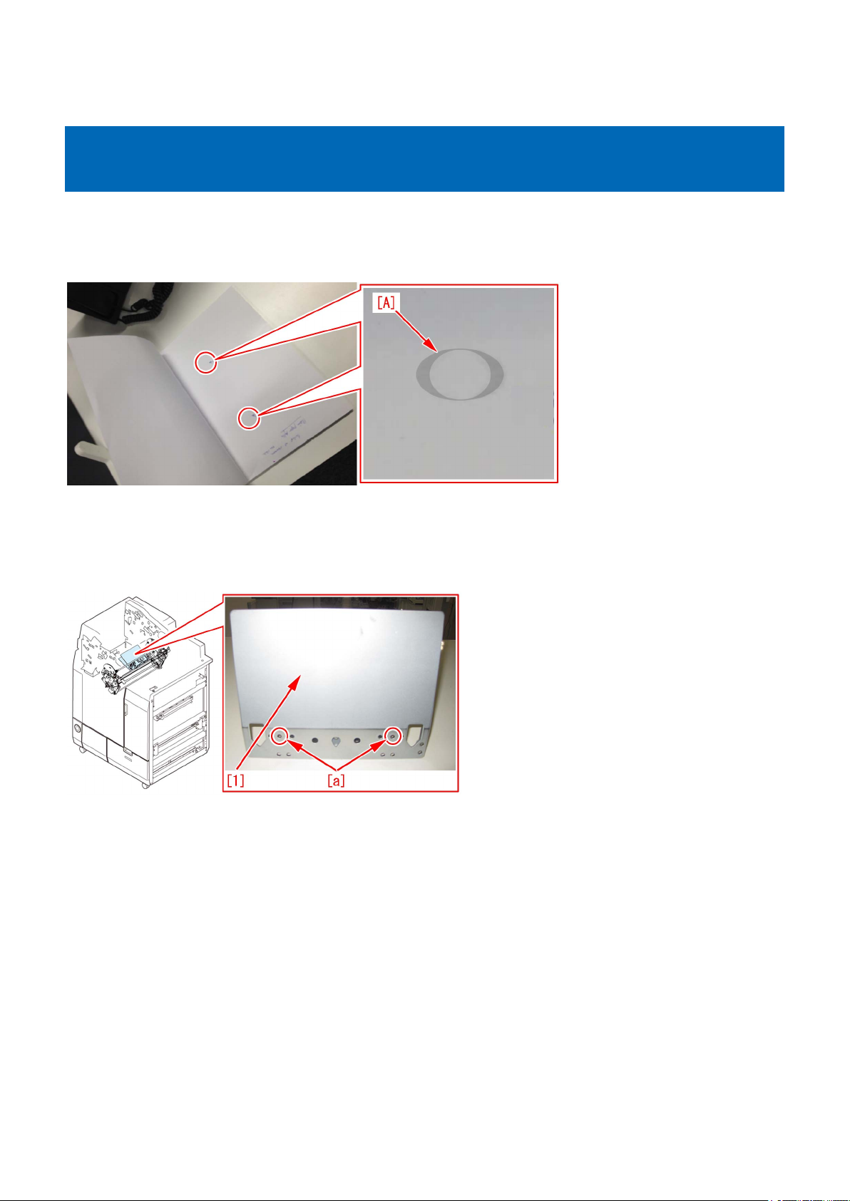
Image Faults
Marks on image caused by friction due to mini gripper edge (Perfect Binder- B1/D1/E1)
[Symptom]
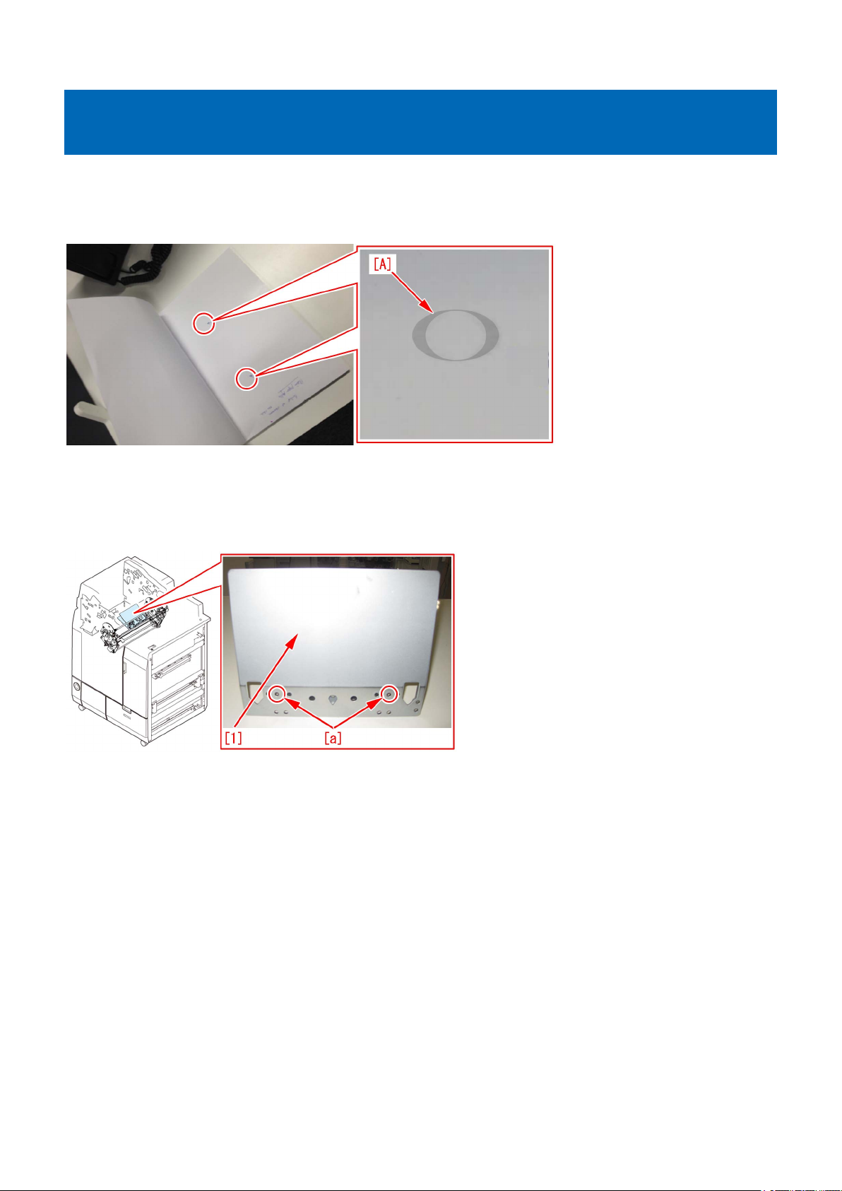
The marks caused by friction [A] may appear on the first and last pages of glued stacked of sheets during printing.
[Reference] This symptom remarkably occurs on glossy paper such as coated paper.
[Cause]
The stuck of sheets loaded on the height tray assembly is fed by sub gripper assembly and then transferred to the main gripper
assembly. The marks caused by friction are put on the first and last pages of glued stacked of sheets due to the edges of round
holes [a] of mini gripper [1] being located at the upper and lower sides of main gripper assembly when transferring.
[Service work]
If the above-mentioned symptom occurs, prepare the sheet kit (4Y8-3138-000) to affix the sheet on the mini gripper being located
on the upper and lower sides of main gripper assembly.
1) Turn off the main power of perfect binder and then unplug the power cord.
2) Remove the parts below referring Service Manual.
- Front Covers (Left/Right)
- Rear Cover
- Rear Upper Cover
- Inner Cover (Upper/Lower)
3) Turn on the right front cover switch and left front cover switch by inserting the service tool or the like.
3
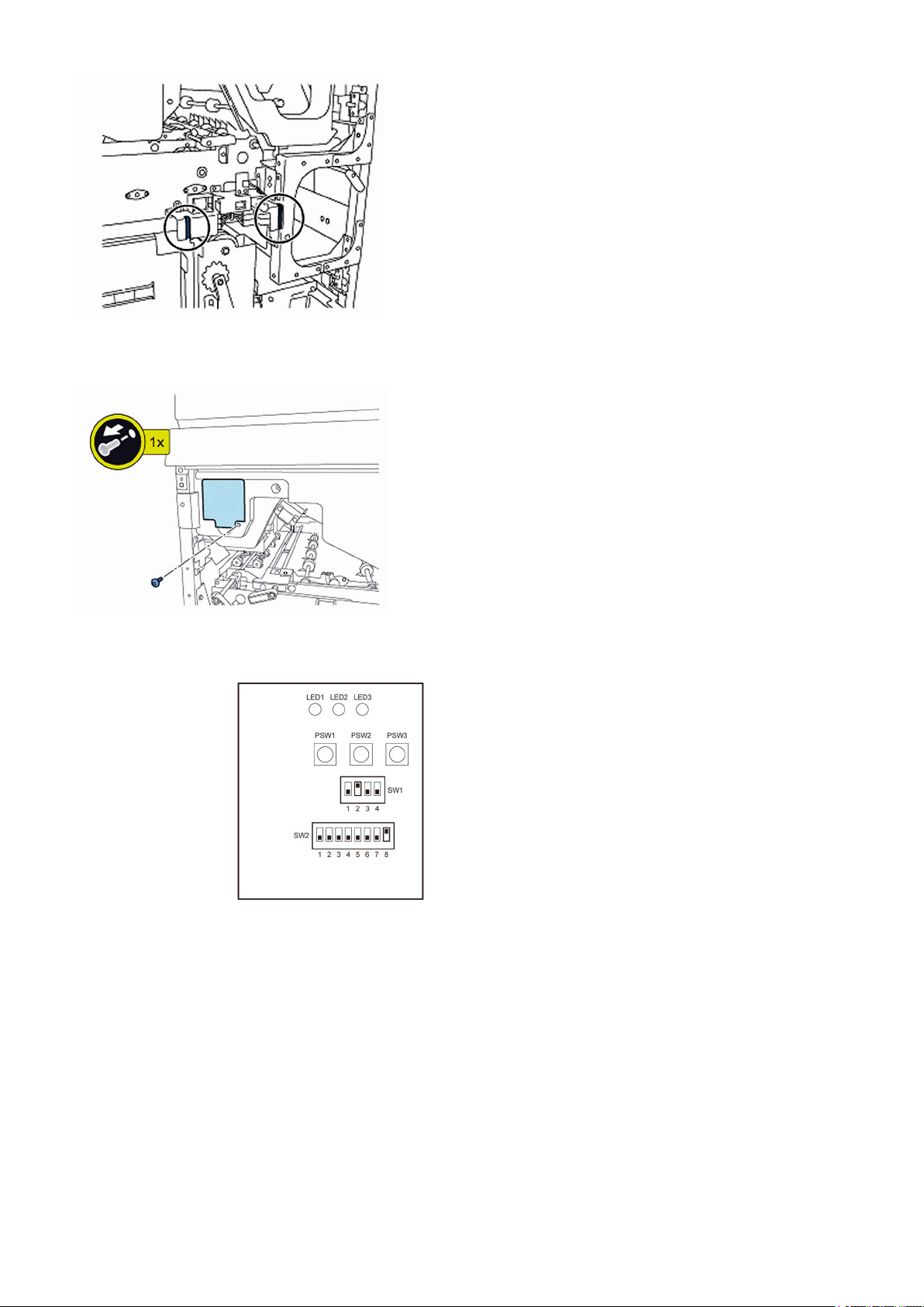
4) Remove the service PCB cover.
• 1 screw
5) Turn on SW1-2 and SW2-8 on the service PCB and set the machine in service mode.
[CAUTION] To keep the machine running in service mode, be sure to do so with the trimming assembly stowed inside.
6) Plug the power cord in the wall outlet.
7) Turn on the power switch and then perform machine initialization operation.
8) Turn off the power switch.
9) Turn on SW1-1 on the service PCB and set the machine in service mode.
4
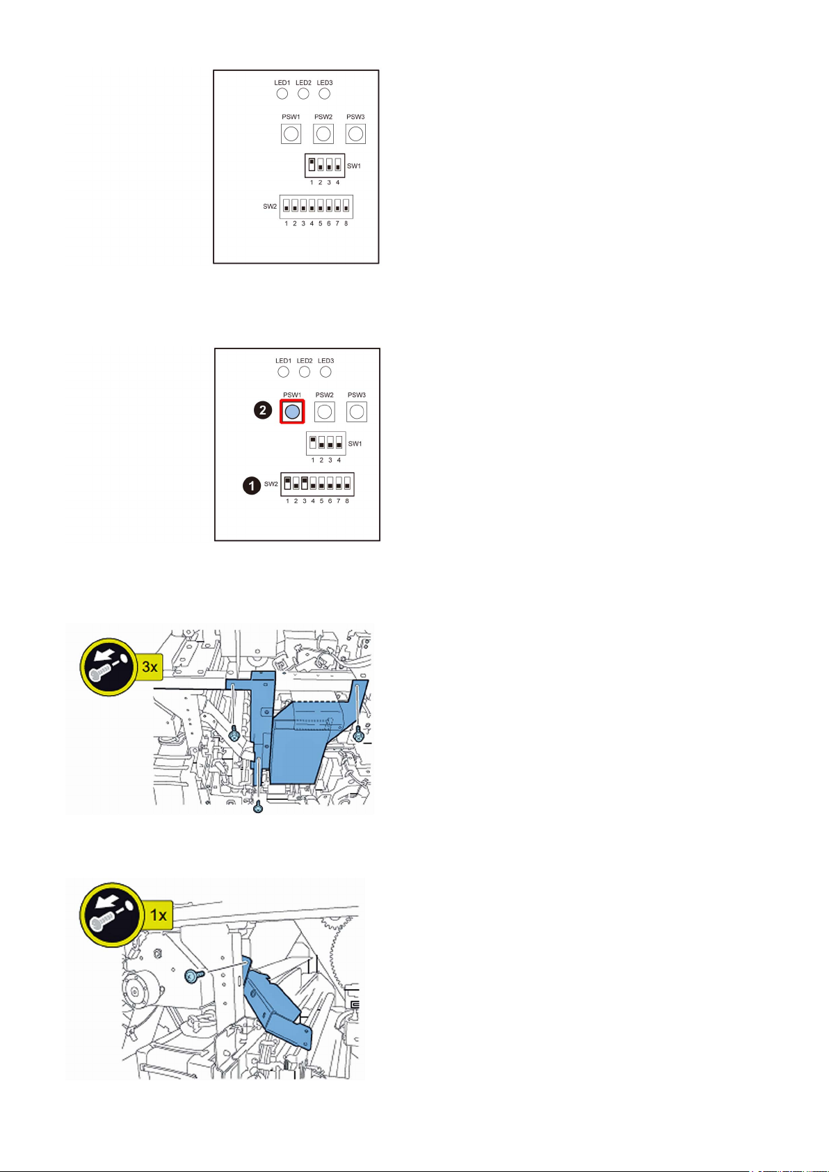
10) Turn on the power switch.
11) Turn on SW2-1 and -3 on the service PCB and then press the push switch PSW1 3 (three) times to stop the mini gripper at
the vertical position.
12) Turn off the main switch and unplug the power cord from the wall outlet.
13) Remove the filter case unit.
• 3 screws
14) Remove the glue transport stay.
• 1 screw
5
[CAUTION] When attaching the glue transport stay, hang the cut part of the stay to the projection of the glue supply entrance.
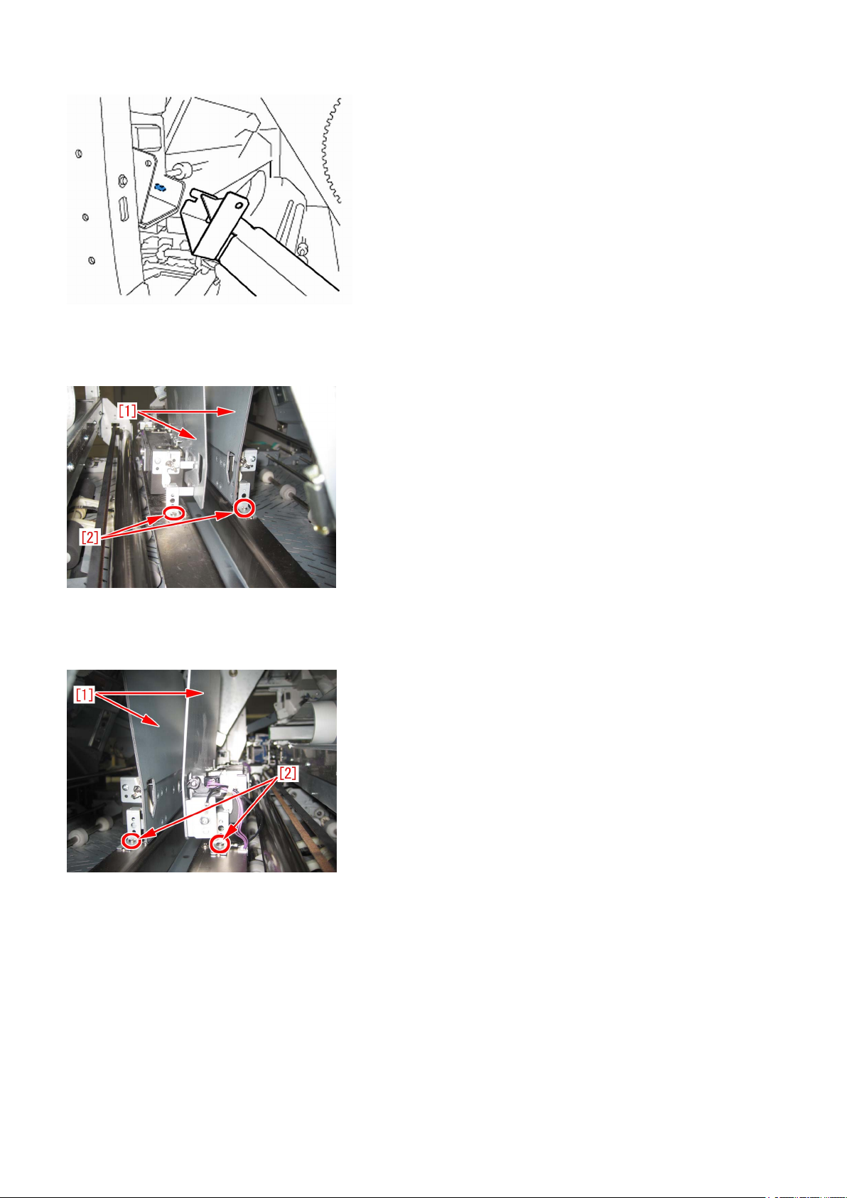
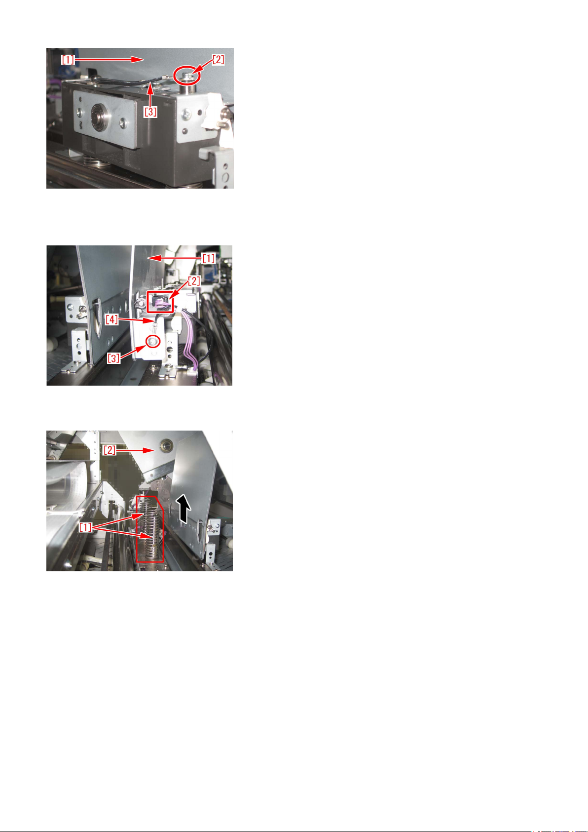
15) Stand behind the machine to face the back side and then remove screws [2] fixing the mini grippers [1].
• 2 screw
[Attention] Be careful not to drop the screws into the machine during the operation.
16) Stand in front of the machine to face the front side and then remove screws [2] fixing the mini gripper [1].
• 2 screw
[Attention] Be careful not to drop the screws into the machine during the operation.
17) Remove the screw [2] being the left side of mini gripper [1] on your left and then disconnect the fixed ground wire [3].
• 1 screw
6

18) Remove the connector [2] being the right side of mini gripper [1] on your right and then remove the screw [3] to disconnect
the ground wire [4].
• 1 screw
19) Lift up (in the direction of the black arrow) left and right mini grippers to remove the 2 (two) mini grippers from the pins [1].
The following photo shows the state that 1 (one) mini gripper [2] has been taken from the back side of machine.
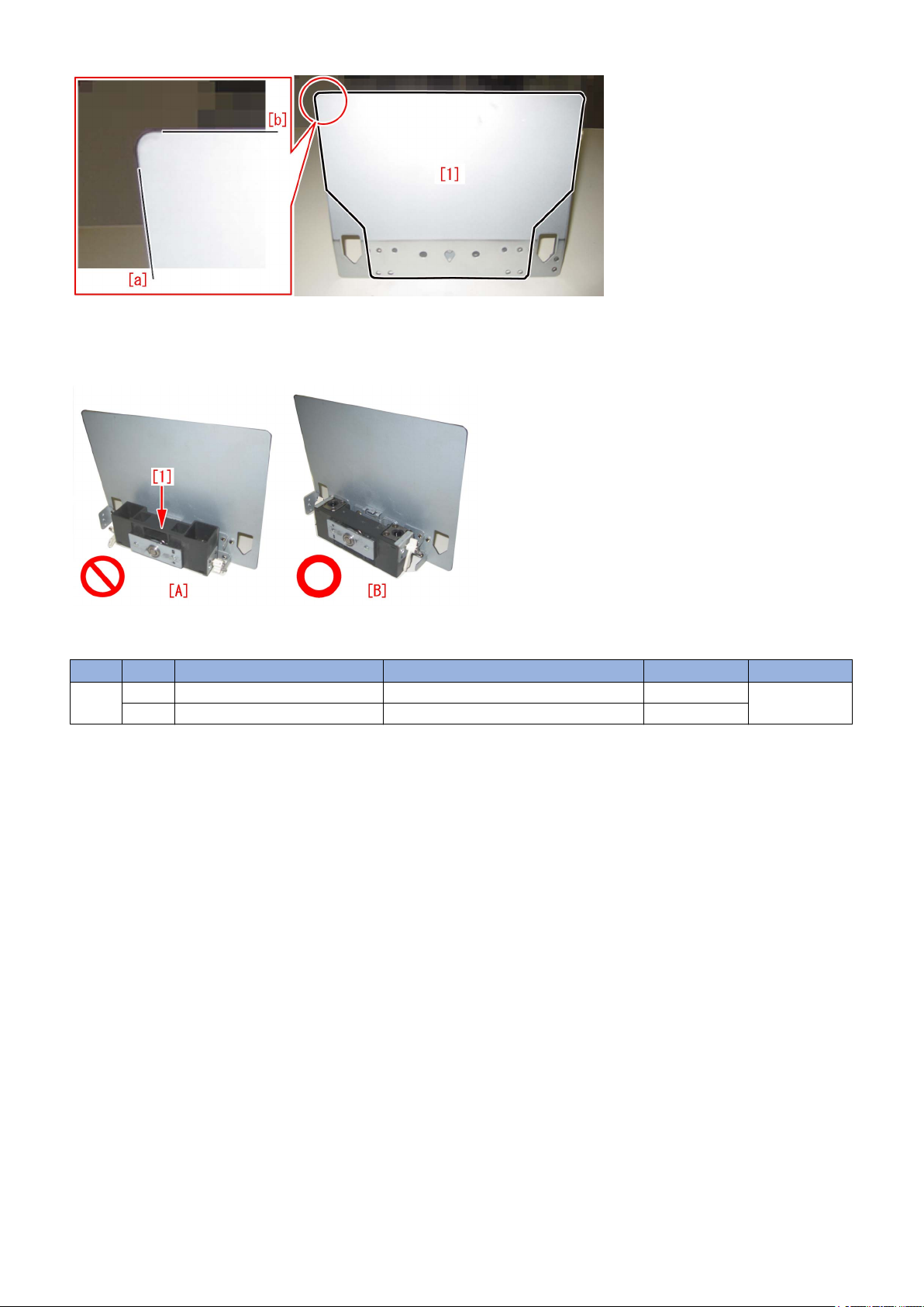
20) Prepare the sheet kit (4Y8-3138-000) to affix the sheet on the mini gripper removed from the main gripper along the following
reference lines.
- Affixing reference line [a]: Affix the left edge of sheet [1] at where it is within 1mm from the edge of mini gripper.
- Affixing reference line [b]: Affix the upper edge of sheet [1] at where it is within 1mm from the upper edge of mini gripper.
Affix the sheet not to protrude from the reference lines [a] and [b].
7

21) Reassemble the parts in the reverse order from Step 13).
[Attention] Make sure that the position of unit [1] being the side of mini gripper is correct and then put the mini gripper.
Photo [A] shows upside-down position of the unit on the side of mini gripper. Photo [B] shows the correct position.
[Service parts]
No. Part Number Description Q'ty Fig.No.
1 Old P51
New 4Y8-3138-000 SHEET KIT 0 -> 1
8
Copier B/W | imagePRESS 1135/1125/1110 Series |
Marks on image caused by friction due to mini gripper edge (Perfect Binder-C1)
[Symptom]
The marks caused by friction [A] may appear on the first and last pages of glued stacked of sheets during printing.
[Reference] This symptom remarkably occurs on glossy paper such as coated paper.
[Cause]
The stuck of sheets loaded on the height tray assembly is fed by sub gripper assembly and then transferred to the main gripper
assembly. The marks caused by friction are put on the first and last pages of glued stacked of sheets due to the edges of round
holes [a] of mini gripper [1] being located at the upper and lower sides of main gripper assembly when transferring.
[Service work]
If the above-mentioned symptom occurs, prepare the sheet kit (4Y8-3138-000) to affix the sheet on the mini gripper being located
on the upper and lower sides of main gripper assembly.
1) Turn off the main power of perfect binder and then unplug the power cord.
2) Remove the parts below referring Service Manual.
- Front Covers (Left/Right)
- Rear Cover
- Rear Upper Cover
- Inner Cover (Upper/Lower)
3) Turn on the right front cover switch and left front cover switch by inserting the service tool or the like.
9

4) Remove the service PCB cover.
• 1 screw
5) Turn on SW1-2 and SW2-8 on the service PCB and set the machine in service mode.
[CAUTION] To keep the machine running in service mode, be sure to do so with the trimming assembly stowed inside.
6) Plug the power cord in the wall outlet.
7) Turn on the power switch and then perform machine initialization operation.
8) Turn off the power switch.
9) Turn on SW1-1 on the service PCB and set the machine in service mode.
10

10) Turn on the power switch.
11) Turn on SW2-1 and -3 on the service PCB and then press the push switch PSW1 3 (three) times to stop the mini gripper at
the vertical position.
12) Turn off the main switch and unplug the power cord from the wall outlet.
13) Remove the filter case unit.
• 3 screws
14) Remove the glue transport stay.
• 1 screw
11

[CAUTION] When attaching the glue transport stay, hang the cut part of the stay to the projection of the glue supply entrance.
15) Stand behind the machine to face the back side and then remove screws [2] fixing the mini grippers [1].
• 2 screw
[Attention] Be careful not to drop the screws into the machine during the operation.
16) Stand in front of the machine to face the front side and then remove screws [2] fixing the mini gripper [1].
• 2 screw
[Attention] Be careful not to drop the screws into the machine during the operation.
17) Remove the screw [2] being the left side of mini gripper [1] on your left and then disconnect the fixed ground wire [3].
• 1 screw
12
18) Remove the connector [2] being the right side of mini gripper [1] on your right and then remove the screw [3] to disconnect
the ground wire [4].
• 1 screw
19) Lift up (in the direction of the black arrow) left and right mini grippers to remove the 2 (two) mini grippers from the pins [1].
The following photo shows the state that 1 (one) mini gripper [2] has been taken from the back side of machine.
20) Prepare the sheet kit (4Y8-3138-000) to affix the sheet on the mini gripper removed from the main gripper along the following
reference lines.
- Affixing reference line [a]: Affix the left edge of sheet [1] at where it is within 1mm from the edge of mini gripper.
- Affixing reference line [b]: Affix the upper edge of sheet [1] at where it is within 1mm from the upper edge of mini gripper.
Affix the sheet not to protrude from the reference lines [a] and [b].
13
21) Reassemble the parts in the reverse order from Step 13).
[Attention] Make sure that the position of unit [1] being the side of mini gripper is correct and then put the mini gripper.
Photo [A] shows upside-down position of the unit on the side of mini gripper. Photo [B] shows the correct position.
[Service parts]
No. Part Number Description Q'ty Fig.No.
1 Old P51
New 4Y8-3138-000 SHEET KIT 0 -> 1
14
Malfunction
Copier B/W | imagePRESS 1135/1125/1110 Series |
The spread glue amount is unstable due to conducting inappropriate procedure to adjust the glue amount(Perfect Binder_A1 / Perfect Binder_C1)
[Symptom]
State of glue application to output products (book) is unstable even if spreading amount of glue has been adjusted.
[Cause]
It was reported in field that the spread amount of glue was unstable even after adjusting the spread amount of glue of Perfect
Binder. Check of the setting of glue amount adjustment in field revealed that glue amount adjustment was not performed properly
due to the following causes:
- Adjustment was performed wrongly
- Lack of explanation on the interaction between the service mode and the user mode both involved with adjusting the glue amount
in technical materials.
Here is the detailed explanation to the above:
<Adjusting work is performed wrongly>
A) Service Mode> SORTER> Adjust> GLUING is adjusted
This service mode is specified as unused in imagePRESS 1135 service manual. However this service mode might be adjusted
in field. The parameter of this service mode is adjusted as a reference position of the gap between stack of sheets (Signature)
and the glue spreading roller at the time of being shipped from factory, and so this setting should not be changed in field. Do not
change the parameter of the service mode otherwise the gap between stack of sheets (Signature) and the glue spreading roller
becomes too close or they might contact each other.
Caution:
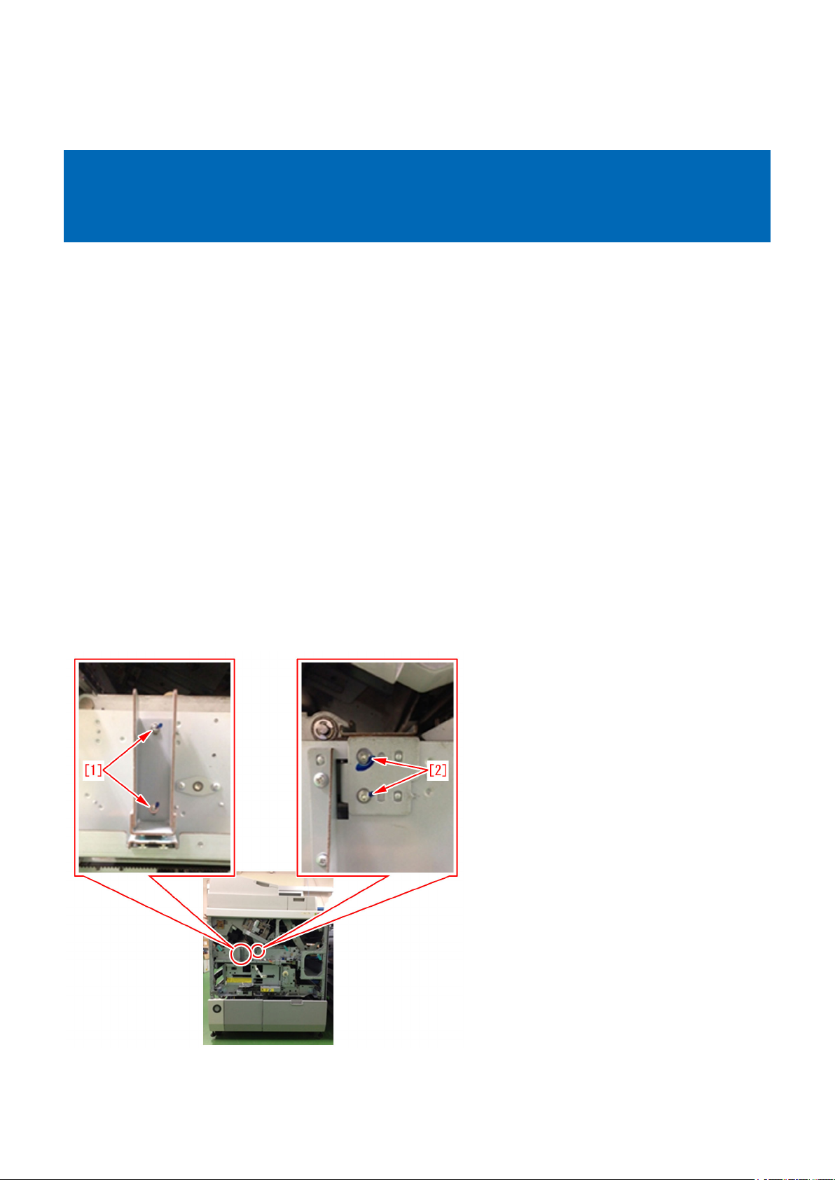
Never adjust the below screws in the filed
- The screws firmly fixed with adhesive on the front side if the device - 1
Remove the lower internal cover and comfirm the screws [1] / [2] shown in the photo below:
- The screws firmly fixed with adhesive on the front side of the device - 2
Remove the upper internal cover and confirm the screws [3] shown in the photo below:
15
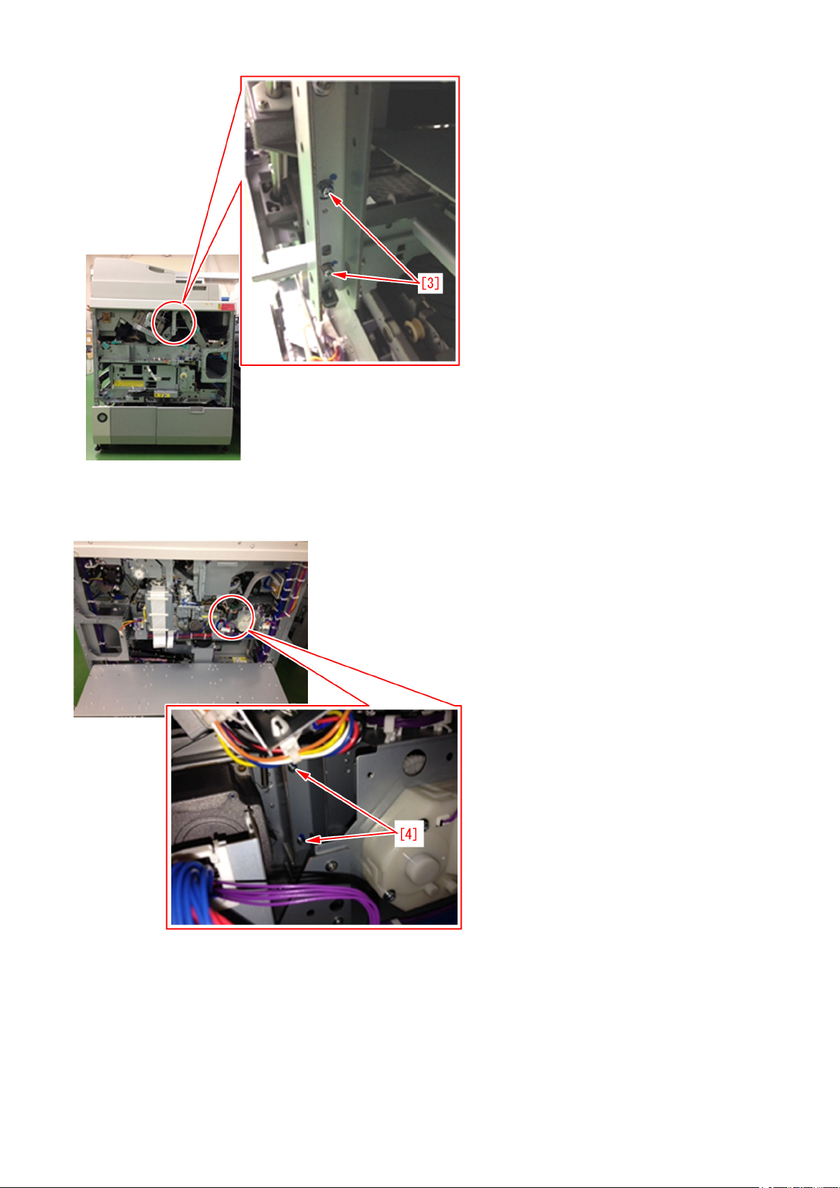
- The screws firmly fixed with adhesive on the rear side of the device
Remove the mount and confirm the screws [4] shown in the photo below:
<Information lacked in the technical materials>
B) Adjusting the spread glue amount in service mode and [Fine adjustment of spread amount of glue in perfect binding] in user
mode.
[Fine adjustment of spread amount of glue in perfect binding] in User Mode (Additional Functions> System Settings> Device
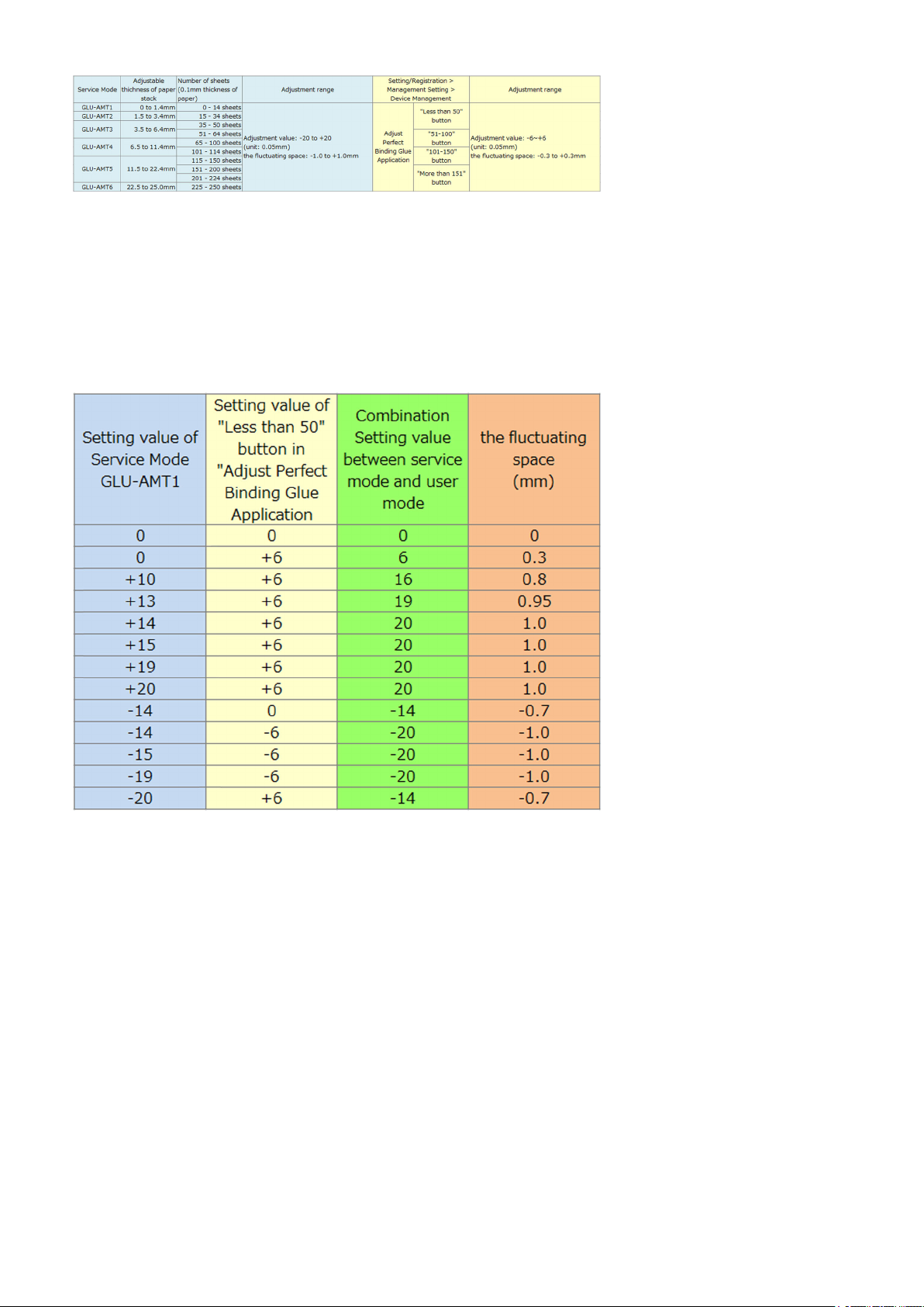
Settings) is to execute fine adjustment of spread amount of glue that is indicated in the service mode (GLU-AMT1 to 6). The table
below shows the relationship between 6 levels of service mode and 4 levels of user mode:
16

For instance, GLU-AMT3 adjustment value is to be applied when a booklet is produced whose thickness of stack of sheets
(Signature) is between 3.5 and 6.4mm (when the thickness of paper is 0.1mm, approximate 35 to 64 sheets). At this time, if the
number of the sheets is between 35 and 50, the parameter of [1 to 50 sheets] setting button in user mode also becomes effective,
and if the number of the sheets is between 51 and 64, the parameter of [51 to 100 sheets] setting button in user mode also
becomes effective. In regard to adjusting the glue amount, it is important to understand the relationship between service mode
and user mode. When to adjust the glue amount using service mode, it is recommended to set the parameter of user mode to
"0" (default value). Both the service mode and the user mode adjust the spread glue amount at the same location, and an
adjustment beyond the adjustable range of service mode is unavailable. The list below shows the sample of main parameters
(adjustable range: -20 to 20)
[Service work]
Perform the work of adjusting the glue amount in the order below:
- Adjusting the glue amount for plain paper
1) Check the condition of paper
2) Check the GLUING parameter on the service label affixed inside the front right door of Perfect Binder
3) Check the GLUING parameter of service mode of the device and enter an adjustment value for correction
4) Check the stack registration guide
5) Print out a sample booklet of stack thickness 0 to 1.4mm
6) Check the condition of glue applied to the booklet and adjust the glue amount
7) Print out again the sample booklet
8) Print out a sample booklet of stack thickness 1.5 to 25.0mm
- Adjusting the glue amount for coated paper
Perform the same procedure as the one for plain paper
Perform the glue amount adjusting work following the procedure below:
<Procedure to adjusting the spread glue amount for plain paper>
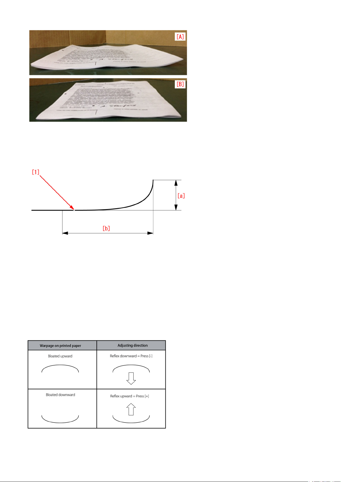
1) Check the condition of paper
Take 10 sheets of two-sided copy using the paper used as stack of sheets (Signature) in bookbinding and check the condition
of curl on paper.
The paper [A] is curled and [B] is not curled.
17

If the paper is not curled, go to the step 2). If the paper is curled, perform curl correction following the procedure below:
[Reference]
The tolerance of curl on the paper [1] that is delivered from copier host machine should be 10mm or less in regard to the height
[a] of the curl, and the length of curl [b] should be 50mm or more.
Even if the curl amount is within the aforementioned specification, the condition of spread glue may be affected by a small amount
of curl due to the variation of elasticity of paper depending on paper type. If 1FA7 or 1FA9 jam occurs, it indicates the possibility
of paper curl. Check if the paper is curled.
1-1) Select Additional Functions> System Settings> Paper Type Management Settings.
1-2) Select the paper type to edit from the list and [Details/Edit].
1-3) Press [Change] in [Curl Correction Level].
1-4) Press [-] and [+] to adjust the correction level for printing in face-up/down modes respectively.
Adjusting in opposite direction of warpage cancels curl out. Perform test copy or print with the paper after adjusting and check
the corrected amount.
[Reference]
- When to see the direction of warpage on paper, place the sheet maintaining its orientation as delivered in the delivery tray.
- Adjust in opposite direction of warpage on paper.
2) Check the GLUING parameter on the service label affixed inside the front right door of Perfect Binder
Check the GLUING label parameter of the information at the time of shipment from factory from service label.
18
3) Check the GLUING parameter of service mode of the device and enter an adjustment value for correction
Check the setting value of Service Mode of the device> SORTER> Adjust> GLUING When the service mode setting parameter
is different from the label parameter, enter the label parameter checked in the step 2).
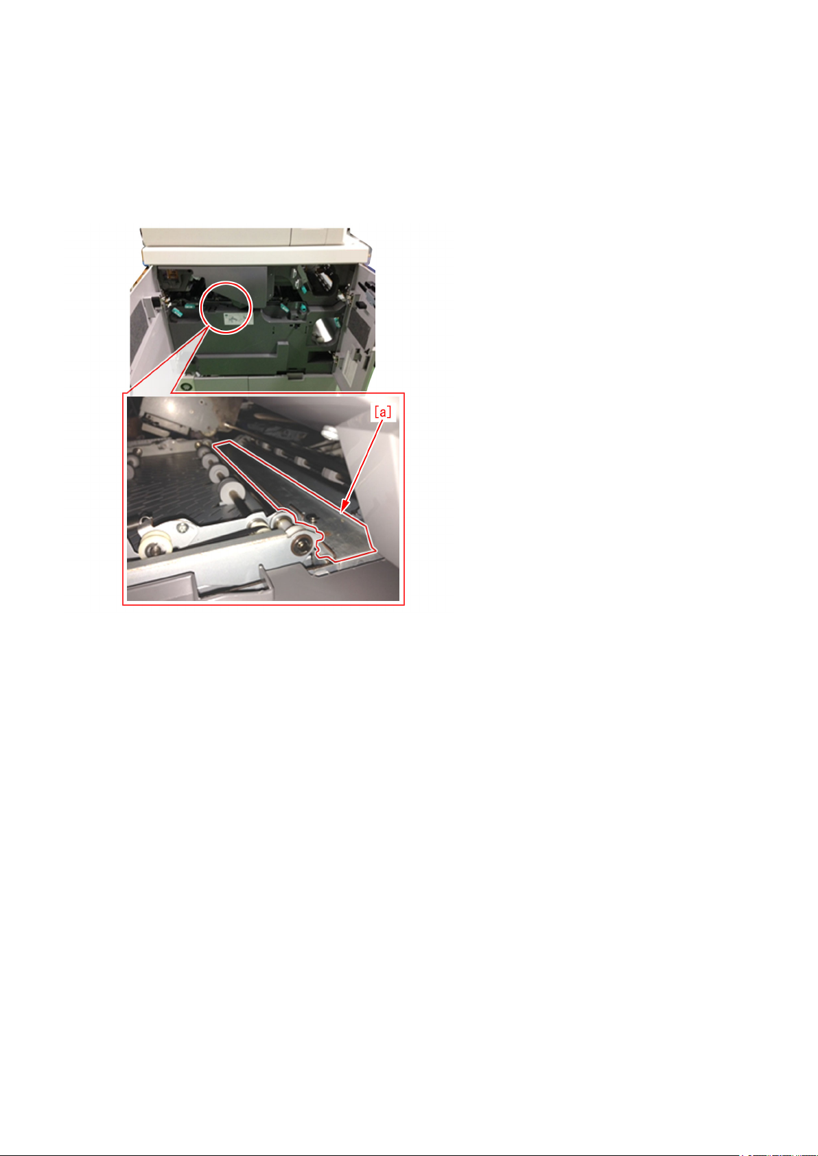
4) Check the stack registration guide
Check if any glue particle is attached on the stack registration guide [a], and make sure to clean if glue particles are attached.
[Caution]
Adjusting the glue amount will not be made correctly if glue particles or foreign substances are attached on the stack registration
guide.
Check the condition of the stack registration guide before adjusting the glue amount and perform cleaning as needed.
5) Print out a sample booklet of stack thickness 0 to 1.4mm
Print out a booklet of stack thickness 0 to 1.4mm using the stack of sheets (Signature) checked in the step 1).
6) Check the condition of glue applied to the booklet and adjust the glue amount
Check the condition of glue applied to the booklet and perform the adjustment according to the condition.
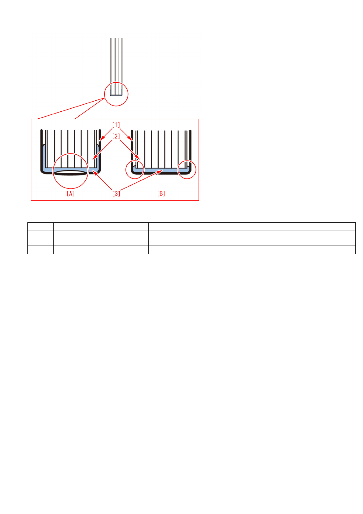
a) Lack of glue at spine, glue come off spine or side glue come off
If an insufficient amount of glue is applied, it generates [Lack of glue at spine/glue come off spine] [A] or [Side glue come off] [B].
In the below figure, [1] indicates cover, [2], stack of sheets (Signature), and [3], glue.
In such a case, go to Service mode> SORTER> Adjust> GLU-AMT1 and adjust by one toward plus (+) direction.
19
Refer to the following table for details.
Location Condition Description
[A] Lack of glue at spine/ glue come off spine Hollows are formed in the glue applied to spine. Otherwise glue is applied but not adhered
to the cover.
[B] Side glue come off The cover easily comes off due to the scanty amount of side glue.
b) Spine glue is pushed and spread over in a T (L) letter shape or an excessive amount of glue
If an excessive amount of glue is applied, it generates [Spine glue spread over in a T (L) letter shape] [C] or [An excessive amount
of glue] [D].
In such a case, go to Service mode> SORTER> Adjust> GLU-AMT1 and adjust by one toward minus (-) direction.
However, as to the spine glue spread over in a T (L) shape, this adjustment only alleviates the inclination, but is unable to eradicate
this symptom due to the structure of the product.
20
Refer to the following table for details.
Location Condition Description
[C] Spine glue is pushed and spread over in
a T (L) letter shape
[D] An excessive amount of glue Due to an excessive amount of glue, the height of the side glue reaches 7mm or more.
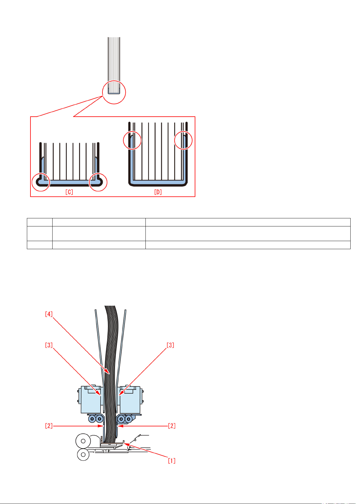
c) Slanted spine glue or imbalance of side glue
If the stack of sheets (Signature) is curled, the stack becomes slightly sagged when stack registration is adjusted as shown in
the picture below.
In the figure below, [1] indicates the stack registration guide, [2], the main gripper, [3], the mini gripper and [4], the stack of sheets
(Signature).
Due to an excessive amount of glue, the glue spreads over the sides (or a side) of the folded
spine cover.
21
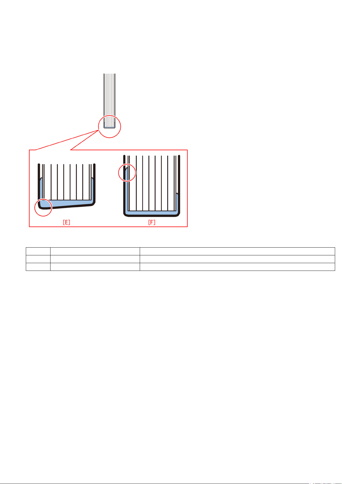
If glue is applied in this condition, the stack goes sagged and registration adjustment is not performed correctly, and this leads
to [Slanted spine glue] [E] or [Imbalance of side glue] [F].
In this case, execute the curl correction in the step 1) and perform again from the step 5).
After performing the step 5), if the [Slanted spine glue] or [Imbalance of side glue] is resolved but the side glue amount is still
excessive, then perform b) Spine glue is pushed and spread over in a T (L) letter shape or an excessive amount of glue.
Refer to the following table for details.
Location Condition Description
[E] Slanted spine glue Spine glue slants.
[F] Imbalance of side glue Only one side of the side glue is excessive and reaches 7mm or more.
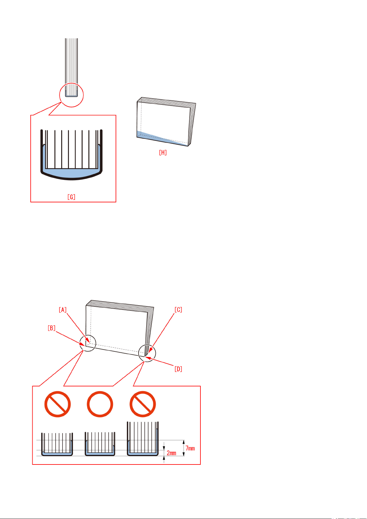
d) Curved spine glue or an imbalance of side glue amount between the front and the rear sides
A curved spine [G] due to insufficient application to corners in folding the spine or a difference of side glue amount between the
front and rear sides [H] due to the foreign substances on the stack registration guide rarely occurs. In this case, check if any
foreign substance is on the stack registration guide as stated in the step 4) and if there is any, remove the foreign substances.
22
[Caution]
Be sure that the specified value of the curved spine is R1.5[mm] or less at the corner of the book when a cover of 128g/m2,
horizontal grain paper [1] is used.
7) Print out a sample booklet of stack again
Print out a book as same as in the step 5) and check the condition of the glue application.
Check if the heights of the side glue at the head and the tail are within the standard of the height shown in the below figure.
- Height of the side glue at the head: Minimum 2.0 to maximum 7.0mm
- Height of the side glue at the tail: Minimum 2.0 to maximum 7.0mm
- Difference of the height of the side glue between the head and the tail: The difference between A and C: 3.0mm or less, the
difference between B and D: 3.0mm or less
If the glue amount is insufficient or excessive, repeat the step 5) to 7).
23

If the glue amount has become appropriate, adjustment of glue amount to the book of GLU-AMT1 stack thickness between 0 and
1.4mm is completed.
Go to the step 8).
8) Print out a sample booklet of stack thickness 1.5 to 25.0mm
As same as GLU-AMT1, go to Service mode> SORTER> Adjust> and adjust the value of GLU-AMT2 to 6 for each stack.
- Stack thickness (1.5 to 3.4mm): Service mode> SORTER> Adjust> GLU-AMT2
- Stack thickness (3.5 to 6.4mm): Service mode> SORTER> Adjust> GLU-AMT3
- Stack thickness (6.5 to 11.4mm): Service mode> SORTER> Adjust> GLU-AMT4
- Stack thickness (11.5 to 22.4mm): Service mode> SORTER> Adjust> GLU-AMT5
- Stack thickness (22.5 to 25.0mm): Service mode> SORTER> Adjust> GLU-AMT6
If Service mode> SORTER> Adjust> GLU-AMT 1 to 6 has been adjusted to the stack thickness in its 6 levels, the adjustment of
the glue amount for plain paper is completed.
[References]
It is not needed to adjust all the GLU-AMT from 1 to 6 for every time.
When GLUING is in the state of the time shipped from factory and after adjusting all the GLU-AMT from 1 to 6, if an adjustment
of glue amount is required with a specific stack thickness, then adjust the GLU-AMT of the relevant stack thickness only.
<Adjusting the glue amount for coated paper>
When to perform the adjustment of spread glue amount for coated paper following "Procedure to adjusting the spread glue amount
for plain paper", perform the work as the same procedure as the step 1) and the step 5) to 8) of "Procedure to adjusting the spread
glue amount for plain paper".
[Caution]
When to adjust the service mode for coated paper in the step 6) and 8), adjust the service modes for coated paper as follows:
<Service modes for plain paper> <Service modes for coated paper>
GLU-AMT1 GLUAMT1C
GLU-AMT2 GLUAMT2C
GLU-AMT3 GLUAMT3C
GLU-AMT4 GLUAMT4C
GLU-AMT5 GLUAMT5C
GLU-AMT6 GLUAMT6C
Points to Note :
Here is the explanation of the complementary information on adding glue and the points to note in works associated with adjusting
spread glue amount:
A) Complementary information on adding glue
As the quantity of glue granules supplied into the glue vat by a supply operation is taken as 3 to 4 granules by calculation, the
quantity of glue granules in the supply operation is not actually counted. In case the glue granules are not properly supplied with
a supply operation due to an assumable failure such as follows, the glue level may decrease and the glue amount applied to the
book during a consecutive printing of books may vary.
- Glue granules clogged in the glue vat and a supply operation supplies only 1 or 2 granules.
- Glue granules clogs in the glue supply route.
Even if the above situation occurred, if the glue supply after having the problem is normal, the condition of glue application will
return to normal.
In addition, the glue amount may appear changed as the value controlled by GLU-AMT changes when stack thickness of book
is suddenly changed between jobs or when the media is changed from plain paper to coated paper even in a same thickness of
the stack.
B) Setting value of Service mode> SORTER> Adjust> GLU-LOW/GLU-UP
Be sure to enter the figures described on the label of the glue vat because the 2 values of this service mode control the glue
amount in the glue vat.
Change of GLU-LOW induces a variation of spread glue amount or an error.
Change of GLU-UP induces a variation of spread glue amount or an overflow of glue.
24

Copier Color | imagePRESS C7011/C7010/C6011/C6010 Series |
The spread glue amount is unstable due to conducting inappropriate procedure to adjust the glue amount(Perfect Binder_B1)
[Symptom]
State of glue application to output products (book) is unstable even if spreading amount of glue has been adjusted.
[Cause]
It was reported in field that the spread amount of glue was unstable even after adjusting the spread amount of glue of Perfect
Binder. Check of the setting of glue amount adjustment in field revealed that glue amount adjustment was not performed properly
due to the following causes:
- Adjustment was performed wrongly
- Lack of explanation on the interaction between the service mode and the user mode both involved with adjusting the glue amount
in technical materials.
Here is the detailed explanation to the above:
<Adjusting work is performed wrongly>
A) Service Mode> SORTER> Adjust> GLUING is adjusted
This service mode is specified as unused in imagePRESS 1135 service manual. However this service mode might be adjusted
in field. The parameter of this service mode is adjusted as a reference position of the gap between stack of sheets (Signature)
and the glue spreading roller at the time of being shipped from factory, and so this setting should not be changed in field. Do not
change the parameter of the service mode otherwise the gap between stack of sheets (Signature) and the glue spreading roller
becomes too close or they might contact each other.
Caution:
Never adjust the below screws in the filed
- The screws firmly fixed with adhesive on the front side if the device - 1
Remove the lower internal cover and comfirm the screws [1] / [2] shown in the photo below:
- The screws firmly fixed with adhesive on the front side of the device - 2
Remove the upper internal cover and confirm the screws [3] shown in the photo below:
25

- The screws firmly fixed with adhesive on the rear side of the device
Remove the mount and confirm the screws [4] shown in the photo below:
<Information lacked in the technical materials>
B) Adjusting the spread glue amount in service mode and [Fine adjustment of spread amount of glue in perfect binding] in user
mode.
[Fine adjustment of spread amount of glue in perfect binding] in User Mode (Additional Functions> System Settings> Device
Settings) is to execute fine adjustment of spread amount of glue that is indicated in the service mode (GLU-AMT1 to 6). The table
below shows the relationship between 6 levels of service mode and 4 levels of user mode:
26
For instance, GLU-AMT3 adjustment value is to be applied when a booklet is produced whose thickness of stack of sheets
(Signature) is between 3.5 and 6.4mm (when the thickness of paper is 0.1mm, approximate 35 to 64 sheets). At this time, if the
number of the sheets is between 35 and 50, the parameter of [1 to 50 sheets] setting button in user mode also becomes effective,
and if the number of the sheets is between 51 and 64, the parameter of [51 to 100 sheets] setting button in user mode also
becomes effective. In regard to adjusting the glue amount, it is important to understand the relationship between service mode
and user mode. When to adjust the glue amount using service mode, it is recommended to set the parameter of user mode to
"0" (default value). Both the service mode and the user mode adjust the spread glue amount at the same location, and an
adjustment beyond the adjustable range of service mode is unavailable. The list below shows the sample of main parameters
(adjustable range: -20 to 20)
[Service work]
Perform the work of adjusting the glue amount in the order below:
- Adjusting the glue amount for plain paper
1) Check the condition of paper
2) Check the GLUING parameter on the service label affixed inside the front right door of Perfect Binder
3) Check the GLUING parameter of service mode of the device and enter an adjustment value for correction
4) Check the stack registration guide
5) Print out a sample booklet of stack thickness 0 to 1.4mm
6) Check the condition of glue applied to the booklet and adjust the glue amount
7) Print out again the sample booklet
8) Print out a sample booklet of stack thickness 1.5 to 25.0mm
- Adjusting the glue amount for coated paper
Perform the same procedure as the one for plain paper
Perform the glue amount adjusting work following the procedure below:
<Procedure to adjusting the spread glue amount for plain paper>
1) Check the condition of paper
Take 10 sheets of two-sided copy using the paper used as stack of sheets (Signature) in bookbinding and check the condition
of curl on paper.
The paper [A] is curled and [B] is not curled.
27
If the paper is not curled, go to the step 2). If the paper is curled, perform curl correction following the procedure below:
[Reference]
The tolerance of curl on the paper [1] that is delivered from copier host machine should be 10mm or less in regard to the height
[a] of the curl, and the length of curl [b] should be 50mm or more.
Even if the curl amount is within the aforementioned specification, the condition of spread glue may be affected by a small amount
of curl due to the variation of elasticity of paper depending on paper type. If 1FA7 or 1FA9 jam occurs, it indicates the possibility
of paper curl. Check if the paper is curled.
1-1) Select Additional Functions> System Settings> Paper Type Management Settings.
1-2) Select the paper type to edit from the list and [Details/Edit].
1-3) Press [Change] in [Curl Correction Level].
1-4) Press [-] and [+] to adjust the correction level for printing in face-up/down modes respectively.
Adjusting in opposite direction of warpage cancels curl out. Perform test copy or print with the paper after adjusting and check
the corrected amount.
[Reference]
- When to see the direction of warpage on paper, place the sheet maintaining its orientation as delivered in the delivery tray.
- Adjust in opposite direction of warpage on paper.
2) Check the GLUING parameter on the service label affixed inside the front right door of Perfect Binder
Check the GLUING label parameter of the information at the time of shipment from factory from service label.
28
 Loading...